This document summarizes an article that proposes modifications to the JPEG 2000 image compression standard to achieve higher compression ratios while maintaining acceptable error rates. The proposed Adaptive JPEG 2000 technique involves pre-processing images with a transfer function to make them more suitable for compression by JPEG 2000. This is intended to provide higher compression ratios than the original JPEG 2000 standard while keeping root mean square error within allowed thresholds. The document provides background on JPEG 2000 and lossy image compression techniques, describes the proposed pre-processing approach, and indicates it was tested on single-channel images.
![criterion. Also this stage reduces the psycho
redundancy of the input image. Quantization operation
is a reversible process and thus may be omitted when
there is a need of error free or lossless comp
the final stage of the data compression model the
symbol coder creates a fixed or variable-variable
length code to
represent the quantizer output and maps the output in
accordance with the code. Generally a variable
code is used to represent the mapped and quantized
data set. It assigns the shortest code words to the most
frequently occurring output values and thus reduces
coding redundancy. The operation in fact is a
reversible one. The decompression reverses the
compression process to produce th
the recovered image
as shown in figure 2. The recovered image may have
lost some information due to the compression, and may
have an error or distortion compared to the original
image.
Figure2 Image decompression
2. BASIC ARCHITECTURE OF
STANDARD
psycho-visual
compression. In
variable-length
System
THE JPEG 2000
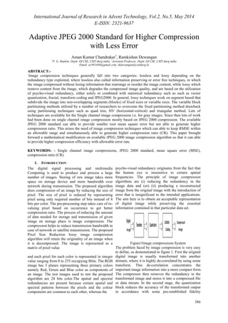
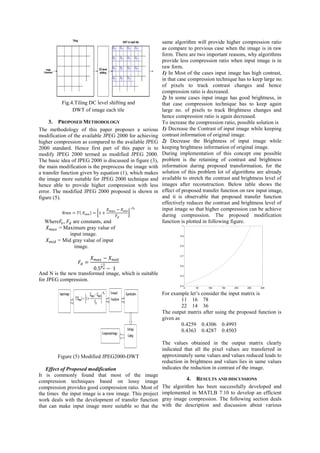
The block diagram of the JPEG2000 encoder is
illustrated in Fig. 3(a). . The discrete transform is first
applied on the source image data. The transform
coefficients are then quantized and entropy coded,
before forming the output code stream (
bit stream).
The decoder is the reverse of the encoder (Fig.4.1b).
The code stream is first entropy decoded, de-de
quantized
and inverse discrete transformed, thus resulting in the
reconstructed image data. Before proceeding with the
details of each block of encoder in Fig. 1, it should be
mentioned that the standard works on image tiles. The
term ‘tiling’ refers to the partition of the original
(source) image into rectangular non-non
overlapping
blocks (tiles), which are compressed independently, as
though they were ere entirely distinct distinc
images. Prior to
computation of the forward discrete wavelet transform
(DWT) on each image tile, all samples of the image
tile component are DC level shifted by subtracting the
same quantity (i.e. the component depth). DC level
shifting ng is performed on samples of components that
are unsigned only. If colour transformation is used, it is
performed prior to computation of the forward
component transform. Otherwise it is performed prior
to the wavelet transform.
At the decoder side, inverse rse DC level shifting is
performed on reconstructed samples of components
that are unsigned only. If used, it is performed after the
computation of the inverse component transform.
Arithmetic coding is used in the last part of the
encoding process. The MQ coder is adopted in
JPEG2000. This coder is basically similar to the QM
QM-coder
adopted in the original JPEG standard [1]. The
MQ-coder is also used in the JBIG
recapitulate, the encoding procedure is as follows [8,
9]:
· The source image is decomposed into
components.
· The image and its components are decomposed
into rectangular tiles. The tile
basic unit of the original or reconstructed image.
· The wavelet transform is applied on each tile.
The tile is decomposed in differen
levels.
· These decomposition levels are made up of
bands of coefficients that describe the frequency
characteristics of local areas (rather than across
the entire tile-component) of the tile component.
· The sub bands of coefficients are quan
collected into rectangular arrays of “code
· The bit-planes of the coefficients in a “code
are entropy coded.
· The encoding can be done in such a way, so that
certain ROI’s can be coded in a higher quality
than the background.
· Markers are added in the bit stream to allow error
resilience.
· The code stream has a main header at the
beginning that describes the original image and
the various decomposition and coding styles that
are used to locate, extract, decode and reconstruct
the image with the desired resolution, fidelity,
region of interest and other characteristics.
· The optional file format describes the meaning of
the image and its components in the context of
the application. It should be noted here that the
basic encoding engine of JPEG2000 is based on
EBCOT (Embedded Block Coding with
Optimized Truncation of the embedded
streams) algorithm, which is described in details
in [20, 21].
Fig.3 Block diagram of the JPEG 2000
coder JBIG-2 standard [7]. To
s tile-component is the
different resolution
sub
quantized and
code-blocks”.
code-block”
s f bit
)](https://image.slidesharecdn.com/paperid-25201490-140904043814-phpapp01/85/Paper-id-25201490-2-320.jpg)
![2
Bc (size of first
compressed image
in bytes)
121096
bytes.
7334 bytes.
3
Bo (size of first
decompressed
image in bytes)
180525
bytes.
180525
bytes.
4 Cr2 30.6807 196.9185
5 R.M.S.E2 8.1344 34.2543
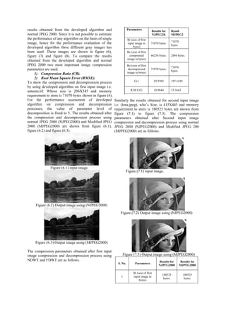
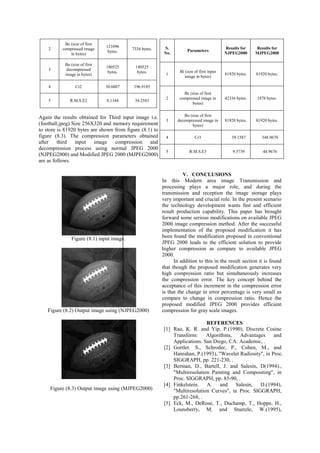
Again the results obtained for Third input image i.e.
(football.jpeg) Size 256X320 and memory requirement
to store is 81920 bytes are shown from figure (8.1) to
figure (8.3). The compression parameters obtained
after third input image compression and
decompression process using normal JPEG 2000
(NJPEG2000) and Modified JPEG 2000 (MJPEG2000)
are as follows.
Figure (8.1) input image.
Figure (8.2) Output image using (NJPEG2000)
Figure (8.3) Output image using (MJPEG2000)
S.
No. Parameters Results for
NJPEG2000
Results for
MJPEG2000
1
Bi (size of first input
image in bytes)
81920 bytes. 81920 bytes.
2
Bc (size of first
compressed image in
bytes)
42336 bytes. 1878 bytes.
3
Bo (size of first
decompressed image in
bytes)
81920 bytes. 81920 bytes.
4 Cr3 39.1587 348.9670
5 R.M.S.E3 9.5739 44.9676
V. CONCLUSIONS
In this Modern area image Transmission and
processing plays a major role, and during the
transmission and reception the image storage plays
very important and crucial role. In the present scenario
the technology development wants fast and efficient
result production capability. This paper has brought
forward some serious modifications on available JPEG
2000 image compression method. After the successful
implementation of the proposed modification it has
been found the modification proposed in conventional
JPEG 2000 leads to the efficient solution to provide
higher compression as compare to available JPEG
2000.
In addition to this in the result section it is found
that though the proposed modification generates very
high compression ratio but simultaneously increases
the compression error. The key concept behind the
acceptance of this increment in the compression error
is that the change in error percentage is very small as
compare to change in compression ratio. Hence the
proposed modified JPEG 2000 provides efficient
compression for gray scale images.
REFERENCES
[1] Rao, K. R. and Yip, P.(1990), Discrete Cosine
Transform: Algorithms, Advantages and
Applications. San Diego, CA: Academic, .
[2] Gortler. S., Schroder, P., Cohen, M., and
Hanrahan, P.(1993), Wavelet Radiosity, in Proc.
SIGGRAPH, pp. 221-230, .
[3] Berman, D., Bartell, J. and Salesin, D(1994).,
Multiresolution Painting and Compositing, in
Proc. SIGGRAPH, pp. 85-90, .
[4] Finkelstein. A. and Salesin, D.(1994),
Multiresolution Curves, in Proc. SIGGRAPH,
pp.261-268, .
[5] Eck, M., DeRose, T., Duchamp, T., Hoppe, H.,
Lounsberry, M. and Stuetzle, W.(1995),](https://image.slidesharecdn.com/paperid-25201490-140904043814-phpapp01/85/Paper-id-25201490-6-320.jpg)