1. E-ISSN: 2321–9637
Volume 2, Issue 1, January 2014
International Journal of Research in Advent Technology
Available Online at: http://www.ijrat.org
40
ON PANEL SIGNALLING SYSTEM FOR TRAINS
WITH AUTOMATIC BRAKING
Mr. Shailesh Mahakal1
, Ms. Rutuja Ruikar2
, Mr. Ameya Shirsat3
, Mr. Mohd Farhan4
Department of Electronics and Telecommunication
Lokmanya Tilak College of Engineering, Navi Mumbai
rutuja.riuikar@yahoo.com1
, ameya25shirsat@gmail.com2
, shailesh5992@gmail.com3
, far786686@gmail.com4
ABSTARCT:
Considering the current state of turmoil in the Indian railways, the controversy surrounding the use or
rather the ineffective use of technology in the railways, there is an aggravating need for some
improvement in technology and at a low cost. One quick-fix solution to this is the indigenously developed,
technologically sound and readily available ‘Anti-collision Device’. But the drawback of that technology is
its high cost of installation. This drawback is overcome by the development of an ‘On Panel Signalling
System in trains with Auxiliary Warning System (AWS)’. The main aim of this project is to develop a
panel which can be mounted on the train’s dashboard so that the motorman has the present status of the
nearest signal at his disposal. If the motorman still overlooks the signal, the train will be brought to a halt
.This is achieved using a circuit made up of micro-controllers, radiofrequency & infrared frequency
transmitters and receivers and RF encoder and decoder.
Keywords: AWS, ACD, On-Panel, Signalling.
1. INTRODUCTION
For the extensive Railway network in India, an efficient management system is required to avoid train accidents.
Although the current safety system is appreciable yet owing to motorman negligence or bad atmospheric
conditions can lead to unavoidable accidents. Our intended system aims at decreasing the margin of error of the
system in existence and thereby making it safer.
2. SYSTEM OVERVIEW
2.1 Transmitter
1. IR TRANSMITTER: It will continously emit IR rays that are invisible to human eyes.
2. IR RECEIVER: WhenIR rays are received by receiver, it will generate logic 1 if not then logic 0.IR
section is basically used to monitor that train is crossing or not.
3. SWITCHES: They are used to select signal generation manually which may be red, green or yellow.
4. RF ENCODER: It will accept 4 bit parallel data from controller and after that encoder will convert
parallel data to serial data.
5. RF TRANSMITTER: It will accept serial data bits at the moderate frequency 433MHz using ASK
modulation and transmit it into air.
6. MICROCONTROLLER 89C51:
• It is used to monitor the switches and generate signal.
• It is used to generate the signal.
2. E-ISSN: 2321–9637
Volume 2, Issue 1, January 2014
International Journal of Research in Advent Technology
Available Online at: http://www.ijrat.org
41
• It is used to generate the command code for signals red, green and yellow.
• The generated code is then send to RF encoder.
• If signal is red then IR receiver is monitored.
• If train crosses the IR signal then it will send stop command.
2.2 Receiver
1. RF RECEIVER: It will accept the data which is sent by RF transmitter from air, demodulate it and send
the data serially to RF decoder.
2. RF DECODER: It will accept the serial data and convert it into the 4 bit parallel data.
3. MICROCONTROLLER 89C2051: It will contineously monitor the RF decoder from command, based
upon command resolve cases red, green and yellow. If command is stop, relay will deactivate.
4. RELAY: It will accept logic 1 or logic 0 from controller. If it is logic 1- output of the circuit will short. If
it is logic 0-circuit will disconnect.
3. E-ISSN: 2321–9637
Volume 2, Issue 1, January 2014
International Journal of Research in Advent Technology
Available Online at: http://www.ijrat.org
42
2.4 Switches
The most familiar form of switch is a manually operated electromechanical device with one or more sets of
electrical contacts, which are connected to external circuits. Each set of contacts can be in one of two states:
either "closed" meaning the contacts are touching and electricity can flow between them, or "open", meaning the
contacts are separated and the switch is non conducting. The mechanism actuating the transition between these
two states (open or closed) can be either a "toggle" (flip switch for continuous "on" or "off") or "momentary"
(push-for "on" or push-for "off") type. In this project three toggle switches are used for indicating Red, Yellow
and Green respectively.
2.5 RF Encoder
HT12E is an encoder integrated circuit of 212
series of encoders. They are paired with 212
series of decoders
for use in remote control system applications. It is mainly used in interfacing RF and infrared circuits. The
chosen pair of encoder/decoder should have same number of addresses and data format.
Simply put, HT12E converts the parallel inputs into serial output. It encodes the 12 bit parallel data into serial
for transmission through an RF transmitter. These 12 bits are divided into 8 address bits and 4 data bits.
HT12E has a transmission enable pin which is active low. When a trigger signal is received on TE pin, the
programmed addresses/data are transmitted together with the header bits via an RF or an infrared transmission
medium. HT12E begins a 4-word transmission cycle upon receipt of a transmission enable. This cycle is
repeated as long as TE is kept low. As soon as TE returns to high, the encoder output completes its final cycle
and then stops.
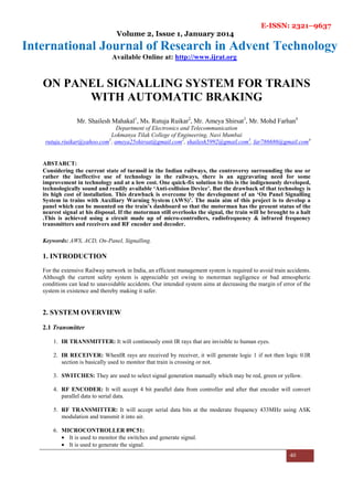
Pin Diagram:
Fig.3 RF ENCODER
4. E-ISSN: 2321–9637
Volume 2, Issue 1, January 2014
International Journal of Research in Advent Technology
Available Online at: http://www.ijrat.org
43
2.6 RF Decoder
HT12D is a decoder integrated circuit that belongs to 212
series of decoders. This series of decoders are mainly
used for remote control system applications, like burglar alarm, car door controller, security system etc. It is
mainly provided to interface RF and infrared circuits. They are paired with 212
series of encoders. The chosen
pair of encoder/decoder should have same number of addresses and data format.
In simple terms, HT12D converts the serial input into parallel outputs. It decodes the serial addresses and data
received by, say, an RF receiver, into parallel data and sends them to output data pins. The serial input data is
compared with the local addresses three times continuously. The input data code is decoded when no error or
unmatched codes are found. A valid transmission in indicated by a high signal at VT pin.
HT12D is capable of decoding 12 bits, of which 8 are address bits and 4 are data bits. The data on 4 bit latch
type output pins remain unchanged until new is received.
Pin Diagram:
Fig.4 RF DECODER
3.6 Microcontroller IC-AT89C51)
• Displays the signal status on signal post based on the manual selection of signals.0
• Converts every signal into 4-bit binary code and sends it to RF transmitter via parallel communication.
• To display system status on the LCD.
• Communicates with IR module when signal is Red.
• Activates emergency brakes during the special condition.
The important features of AT89C51 are:
• 128 x 8-bit Internal RAM
• 32 Programmable I/O Lines
• 4K Bytes of In-System Reprogrammable Flash Memory Endurance: 1,000 write/Erase Cycles.
3.7 Microcontroller (89c2051)
• The microcontroller used at the train side is to be installed on the toy train set. So we have used small
size, light weight 20 pin microcontroller 89c2051.
• It receives the data from the decoder parallel containing the information of the status of the signals. It
displays the status of the signal on the panel of the motorman.
• It energizes and DE energizes the relay unit.
5. E-ISSN: 2321–9637
Volume 2, Issue 1, January 2014
International Journal of Research in Advent Technology
Available Online at: http://www.ijrat.org
44
3.8 Relay
• A relay is a simple electromechanical switch made up of an electromagnet and a set of contacts. Relays
are found hidden in all sorts of devices. In fact, some of the first computers ever built used relays to
implement Boolean gates.
Fig.5 Relay
4. Conclusion
The designed On panel signaling system is very useful for railway system mainly in rain and fog prone area and
offered following advantages and limitaions
Advantages:
• Modeling of existing railway techniques and implementing their improvements.
• All features can be projected in a small area (toy train).
• Sturdy equipment designed to meet working conditions of railway operations.
• Compact apparatus with high degree of operational reliability.
• Immune to climatic conditions most of the times.
Limitations:
• Implementation of real world Railway system into Toy Train model.
• Existing system includes single and double yellow signals which are not implemented.
Future scope:
• On-panel signal system can be implemented using Zigbee technology.
• Anti-Collision Device can be implemented using Global Positioning System (GPS).
References
[1] Mr.Abhijit S Khadilkar, Mr. Anish S Kirloskar, Mr. Pratik S Adagale “On panel signalling & safety system
for railways” International Journal of Infinite Innovations in Technology in April 2009.
[2] 8051 Programming and Embedded Systems using C and Assembly Language by Muhammad Ali Mazidi and
Janice Gillispie Mazidi (Micocontroller programming and interfacing of temperature sensor and IR LEDs with
AT89c52)
[3] www.electronicsgarage.com
[4] http://www.irfca.org/docs/mumbai-aws.html
[5] http://seminarprojects.com/Thread-acd-anti-collision-device-full-report
[6] http://indianrailwayemployee.com/content/anti-collision-device-acd
[7] www.electronicsforyou.com