Recent Advancements in Piping industry and Piping materials.
Paper
1. Presented at the PPSA Seminar on 16
th
November 2011
THE BLUE STREAM PIPELINE INSPECTION PROJECT
AN OVERVIEW OF THE CHALLENGES FACED IN ORDER TO CLEAN AND INSPECT
THE 24” x 380 KM PARALLEL NATURAL GAS INTERCONNECTOR PIPELINES
BETWEEN RUSSIA AND TURKEY
By: Ron James PII Pipeline Solutions, EURA Regional Sales Manager
William Herron PII Pipeline Solutions, Chief Engineer
1. Project Introduction
Infrastructure Overview
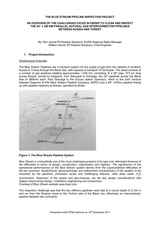
The Blue Stream Pipelines are a transport system for the supply of gas from the network of southern
Russia to Turkey through the Black Sea, with capacity to transport 16 Gm3/year. The asset consists of
a number of gas pipelines totalling approximately 1,250 km, consisting of a 56" pipe, 373 km long
across Russia, owned by Gazprom, from Stavropol to Dzhubga, two 24" pipelines across the Black
Sea of 380Kms each, from Dzhubga to the Durusu station (Samsun); which is the Joint Venture
between Gazprom & ENI (Blue Stream Pipeline Company- BSPC) and a 48", 470Km pipeline linking
up with pipeline networks at Ankara, operated by Botas.
Figure 1- The Blue Stream Pipeline System
Blue Stream is undoubtedly one of the most challenging projects of its type ever attempted because of
the difficulties in terms of design, construction, organisation and logistics. The significance of the
operational performances on the Blue Stream system derives from the unprecedented difficulties of
the two sea-lines. Geotechnical, geomorphologic and bathymetric characteristics of the seabed, to be
traversed by the pipelines, presented varied and challenging features. Ultra deep water, H
2
S
environment, steepness of the slopes and geo-hazards, are the key design considerations that
Saipem faced during design, installation engineering and construction.
Courtesy of Blue Stream website www.bspc.com
The inspection challenge was that the two offshore pipelines were laid at a record depth of 2,150 m
and run from the Russian shore to the Turkish side of the Black sea, effectively an interconnector
pipeline between two continents.
2. Presented at the PPSA Seminar on 16
th
November 2011
0 20 40 60 80 100 120 140 160 180 200 220 240 260 280 300 320 340 360 380
Kilometer Post (km)
-2250
-2000
-1750
-1500
-1250
-1000
-750
-500
-250
0
WaterDepth(m)
Russian Shelf
Russian Slope
Russian Apron
Turkish Shelf
Turkish Slope
Turkish ApronAbyssal Plain
Figure 2 - Profile of the Black Sea along Blue Stream pipeline route, showing the 7 bathymetric
provinces.
Project Requirements
Pipeline Cleaning & Proving - to ensure the pipeline is in a clean enough condition to receive
the subsequent inspection vehicles.
Calliper – Detecting any dents or ovalities in the ‘as-laid’ pipelines.
Out-of-Straightness Survey – to detect and measure the out-of-straightness or strain events in
the as-laid conditions or and free spans.
Magnetic Flux Leakage (MFL) High resolution Metal loss Survey – to inspect for any metal
loss or corrosion.
Inspection Project Challenges
Below are listed the project challenges for the inspection tool design:
• Diameter: 24” with reduced bore tees – diameter 505mm (83% of Outside Diameter)
• Line lengths: 380 & 387 Km
• Depth max.: 2140m (7021’)
• Pressure: 250 bar (3625psi)
• Temperature: - 10C to +55C
• 7D bends
• 32mm wall thickness
• Ball Valves
• Barred tees
• Buckle arrestors
• Internal epoxy coating
• Flow ~ 2.5m/s
3. Presented at the PPSA Seminar on 16
th
November 2011
2. Project Approach
A feasibility study was done up-front in the project to review the pipeline and operational specific
features and to identify the technical risks. The main challenges on the inspection system were
identified as:-
Wall Thickness requirement of 32mm
Reduced bore passing – to cater for thick wall transition at the tee near the receive trap
Pressure 250bar
The clients concerns for the tool running in the pipeline were:-
‘NO STUCK TOOLS’ – The number 1 criteria was that any form of lodgement was
unacceptable.
Internal coating – the inspection tool must not damage the internal pipeline coating.
Durability of the tool must last the 380Km+ range.
Engineering layouts and early magnetic analysis was done on the 24-30” MFL inspection to verify the
bore passing and wall thickness capability. Technical and operational risks were identified, and a
proposal produced, which outlined what needed to be done to convert the tool, and tests to be
completed early in the main programme to improve the probability of success.
The feasibility study established that all of the challenges could be met using PII’s 24-30” Multi
Diameter Magnetic Flux Leakage Tool.
This proposal was accepted by BSPC and the PII team embarked upon the development changes to
the 24-30” Multi Diameter MFL inspection tool to satisfy the specific requirements for this project.
The subsequent development phase concentrated on the following:-
Engineering Design & Proof of Concept
Sizing model generation
Tool Design & Build
Project Execution
3. Challenge Specifics
The BSPC pipeline was particularly challenging from a design and operational perspective due to the
fact that it was 2140m deep in the Black Sea, gas at 250bar, thick wall pipe ~35mm & local full bore
forged tee at Receive of 505mm diameter (i.e. 83% of nominal outside diameter). The following
sections discusses the specific challenges faced and what was done to mitigate the associated risks.
CAD Simulation & Magnetic Modelling
One of the biggest challenges to the tool design was the saturation of the pipe wall with enough
magnetic flux to conduct a successful inspection. 3D CAD modelling simulations were done to model
the bore passing and feature passing requirements of the BSPC pipeline and at the same time check
for magnetic saturation in the thick wall sections. The most severe geometry feature in the pipeline
was the diameter 505mm (17% restriction) thick wall tee near to the receive site and the thick wall
sections circa 32mm.
4. Presented at the PPSA Seminar on 16
th
November 2011
Buckle arrestor sections of pipe spool were integrated as part of the pipeline which was ~47mm thick.
The client was not interested in inspection through these sections due to the excessive corrosion
allowance built in. However PII were challenged to see what we could derive from inspections at the
transition between the nominal pipe and the thick wall buckle arrestors.
Enhanced Flux handling techniques used to generate an articulated bar return path design that was
superior in handling the magnetic field compared to conventional sweeps brush techniques. This was
based on proven concepts previously used to increase the wall thickness capabilities on small
diameter tools but not previously used on a segmented body tool. The tool was designed with the
most powerful commercially available rare earth magnets in the maximum space volume to achieve
the local full bore passing requirement of the thick wall tee.
The articulated return path design of magnetic vehicle was designed for a multi diameter application
24 to 30”. For BSPC the requirement was for single diameter, so to maximise reliability the articulated
mechanism for the return path bars was effectively locked down in the 24” mode, to allow the
magnetic vehicle to behave like a fixed body.
Figure 3- Magnetic modelling of the Flux intensifier return path bar
Figure 4- Magnetic modelling of the array of return path bars to check the uniformity of the field
distribution between bars and along the axis between poles
5. Presented at the PPSA Seminar on 16
th
November 2011
Figure 5- Predicted magnetic field levels
This graph shows the predicted magnetic field levels for the magnetiser arrangement in different wall
thicknesses in the axial orientation. It is used to check the stability or flatness of the field levels relative
to axial position. This is then used to determine the optimum position for the sensors. As can be seen
from the above graph the field levels are relatively flat for the BSPC range of wall thickness allowing
us some flexibility where the sensors can be positioned axially.
The analysis of the magnetic circuit predicted the following performance:-
Table 1- Magnetic Circuit Performance
In summary, following all design and testing, the results demonstrated that the magnetic circuit was
capable of inspecting 32mm WT at 2m/s minimum.
Pipeline Inspection Data Analysis Software & Pipeline Sentencing
Due to the high pressures exerted on the external surface of the pipeline, by both the water depth and
the pressure of the gas inside the pipeline, the sentencing of the pipeline had to be carefully taken into
consideration to ensure the actual forces were being calculated at any given depth. The data analysis
software produced for the BSPC subsea network took into account the external collapse pressures as
well as internal process forces dynamically and progressively for the entire length of the assets.
Pig Recovery Strategy
It was essential during the design and development of the tools that on no account should any tool
become stuck in the pipeline and block production flows.
Most large size complex intelligent inspection systems are multi module to accommodate the magnetic
module, front end processing data storage and power supply functions. It is therefore not
recommended to push the tool from behind, as the tow couplings would tend to jack knife. This could
24Inch 13.70 (0.539) 25.4 (1.000) 38.10 ( 1.500) 32.0 ( 1.260)
Pipe
Diameter
Predicted Min WT /
mm (Inch)
BSPC Max WT /
mm (Inch)
* Pull Throughs required to verify top inspection speed for 32mm thickness inspection and static field
measurements
BSPC Min WT /
mm (Inch)
Predicted Max WT /
mm (Inch)
6. Presented at the PPSA Seminar on 16
th
November 2011
damage the tool to the extent that the rear most modules behind the magnetic vehicle become
disconnected from the main inspection train.
PII had previously designed a 24-30” multi diameter thick wall inspection system for operation in liquid
pipelines at depths of 7700ft that had to negotiate vertical asymmetric equal and unequal wyes. This
experience was brought onto the BSPC project to ensure that the design of semi rigid tow bars could
accommodate the various loading conditions imposed during normal pigging operations and at the
same time be structurally sound enough to be able to be pushed from the rear.
Engineering layouts and simulations were done to ascertain the best combination of semi rigid tow
coupling whilst connected to the adjacent vehicles. The designs were prototyped and tested to ensure
satisfactory performance for:-
Tensile loading – ability to pull the trailing modules through the pipeline
Compression loading – ability to withstand the compressive loads generated when the high
drag lead module suddenly slows down at a thick wall transition or bend and the inertia of the
trailing modules tries to push it closer
Offset Strut loading – ability to withstand the offset loads caused during negotiation of thick
wall transitions or bends – as per compression loading case – but when the axis of the
adjacent modules are offset – i.e. not in line
Bending loading – ability to withstand the bending loading induced on the tow bar whilst
negotiating bends
Torsion loading – The trailing modules of MFL pigs are designed to induce rotation of the
tool to ensure even wear and improve drive and sensor reliability. The tow bar assembly has
to withstand the torsional loading to minimise the torsional misalignment between the main
corrosion sensors and the positional recording system in the data acquisition pack, located in
the trailing vehicle.
As can be determined from the above, the design of a semi-rigid tow coupling is not straight forward.
PII designed several prototype units, manufactured the hardware and conducted a series of prototype
tests that were necessary to hone in on the final design. Figures 6 and 7 show some of the tests that
were done to validate the design.
Figures 6 & 7- Testing of Prototype Semi Rigid Tow Coupling
Once the tow bar design was finalised all that needed to be done was to fit a flat pushing facility at the
rear of the train, to allow a recovery pig to push against.
As part of the system tests, PII successfully demonstrated that a recovery pig could be manoeuvred
up behind the stationary inspection tool and push the whole arrangement along through the test rig.
This arrangement was previously verified across a test rig which contained an asymmetric wye.
7. Presented at the PPSA Seminar on 16
th
November 2011
Location & Tracking
An electromagnetic transmitter was fitted to the tool as standard and magnetic sensitive timer boxes
placed at strategic positions on the onshore pipeline sections so that in the event that the pig was
stuck, there was a possibility of finding it. For the subsea piece of the pipeline, the transmitter could
be detected by a suitable receive device fitted to an ROV, however the client insisted that the pig
could be recovered by another pig - hence the emphasis on recovery strategy. Acoustic monitors were
fitted at both Launch and Receive sites so that the pig position along the pipeline could be tracked and
monitored
Pipeline Pressure 250bar
Standard MFL inspection systems in the PII fleet are certified for operation in both liquid and gas to
220bar. The 24-30” system used to inspect BSPC pipeline was tested and certified for 400bar
operation in liquid pipelines only. The requirement for operation at pressures up to 250bar meant that
we had to conduct design verification tests with the sensor hardware and external harnessing in
compressible products up to 250bar. Tests were successfully passed.
Figure 8- MFL sensor arrangement
Pipeline Cleaning
Figure 9- Cleaning Tool
8. Presented at the PPSA Seminar on 16
th
November 2011
The design of the cleaning tools had to be carefully considered. The removal of any dust or debris in
the pipeline is crucial in obtaining a successful inspection; however, the abrasion was a factor for all
pig runs and the protection of the integrity of the coating. Figure 9 shows the received cleaner, with
minimal wear considering the pipeline length. The quantity of dust and debris was very small due to
the quality of the gas and transportation process and the excellent construction of the pipeline.
Figure 10 -The MFL pig received in Turkey after 387Km run
4. Project summary
The two pipelines were successfully inspected and the results issued to BSPC. Figure 10 illustrates
the safe receipt of the MFL tool following the 387Km run. The operation included the safe tracking of
the pigs on both of the onshore sections acoustically and magnetically out of the traps and safely into
the receive traps. Launching the tools in Russia and receiving in Turkey presented the team with
customs and local certification challenges, including the requirement for local operating licences and
permits to import and operate the tools in both countries, and to produce all documentation in both
languages.
The overall design & operation was undertaken in a very cooperative and open spirit. The challenges
and hurdles were surmounted at each design stage and all milestones presented and evaluated
before moving to the next.
All of the pigs that were launched into the BSPC pipelines were safely received on time, and the
rescue pig mobilised with the equipment was not required during operations. The calculated run time
was 92 hours and the actual run times were within 15 minutes of the calculations. Credit must go to
the SAIPEM team, who were technical consultants for the project for the computation of the run times.
9. Presented at the PPSA Seminar on 16
th
November 2011
Figure 11- Launch Site in Russia
Figure 12- Photograph of the two receive traps in Turkey
References
Massimo Volpini- Technical Manager- BSPC
Francesco Tommasi-Procurement Manager- BSPC
Claudio Mondo- Project Manager- SAIPEM Energy Services
East TrapWest Trap