Bajaj Allianz Life Insurance Company - Insurer Innovation Award 2024
CE1-Jose (1).docx
1. CARRER EPISODE 1
a) Introduction:
1.1 The first career episode focuses on my Master's research project titled "Three-
dimensional numerical simulation of distortion pattern of GRP pipes during
pipejacking." I undertook this project as a research student, where I served as a co-
author of a journal paper. The purpose of this research was to fulfill the requirements
of my Master's Degree in Civil Engineering with Business. The research work was
carried out at the Melbourne School of Engineering, The University of Melbourne,
Australia. The entire research project spanned one year, and I submitted the final
research article in 2020.
b) Background:
1.2 This project focused on investigating Pipejacking as a Microtunneling technique, which
is known for its nondisruptive underground installations of utility services. Extensive
research has been conducted on various aspects of this technology, including the
construction process, piping material, and pipe-soil behavior. However, the use of new
composite materials, such as Glass Reinforced Plastics (GRP), as jacking pipe material
has not been thoroughly explored, resulting in overdesigning of the construction
process and pipe section.
1.3 The project’s objective was to analyze various geotechnical, systematic, and material
factors in order to estimate the strain measurements (hoop and longitudinal) of the
Kalkallo Creek sewer using FBG sensors. Moreover, by evaluating the deformation
patterns, this research aimed to identify potential design improvements for pipe-
jacking techniques. Based on the observed behavior, a series of hypotheses were
developed and evaluated to either confirm or refute the proposed propositions
1.4 Being a research student, I was working on the following engineering activities:
Studied the existing research articles and journals to investigate the potential of
pipejacking as a micro-tunnelling technique for underground system installations.
Selected the project area to collect field data regarding installing FBG sensors on
GRP pipe No. 143 at KCMS site.
Carried out a series of investigations to simulate the process of pipejacking,
primarily focusing on predicting jacking forces and analyzing ground movement
resulting from pipe jacking installations.
Designed three numerical models in ANSYS platform that study three different
conditions of the GRP pipe.
Carrying out numerical model validation by developing graphs.
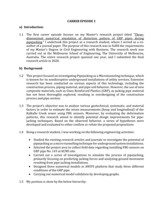
1.5 My position is show by the below hierarchy:
2. c) Personal Engineering Activities:
1.6 Initially, I conducted extensive research on the challenges faced by current urban areas
in accommodating rapid population growth and rural migrations. During the literature
review, I focused on pipejacking as a micro-tunnelling trenchless technique for
underground system installation. Furthermore, I examined various aspects, including
the behavior of pipes, the use of glass reinforced plastic, and the application of fiber
optic sensors for field monitoring.
1.7 Then, in the team meeting with the senior investigator and industry partner, I discussed
all identified challenges and research findings and we decided to utilize the ANSYS 3D
finite element methods platform to recreate and interpret the deformation of a GRP
pipe during the pipejacking process in real field conditions. I also presented the
research main idea to the supervisor who approved it after several discussions.
1.8 I collected field data from the Kalkallo Creek Main Sewer (KCMS) project in Melbourne.
The monitored pipe section, No. 143, was jacked between shafts KAL-10 and KAL-11 at
a depth of 12.4 m. The data covered a 51 m drive, with 24 m captured during logging
sessions. The GRP pipe by IPLEX Pipelines had specific dimensions and properties, and
FBG sensors provided strain measurements.
1.9 I also studied about the FBG sensor configuration in the longitudinal fibre provided
valuable strain measurements at different locations along the pipe section. I selected
this arrangement of the FBG sensors as a reference for locating data points in the model.
Also, I identified that by simulating the pipejacking conditions in ANSYS and comparing
the numerical model with the field monitoring strain data, I would enhance our
understanding of the structural deformation in GRP pipes. I ensured that this analysis
would allow to establish connections between the numerical model and real-world
conditions, including construction processes, by conducting a sensitivity analysis of key
variables.
Industry Partner (Senior
Technical Director Tunneling
and Engineering Geology GHD
Pty Ltd, Melbourne) Australia
Supervisor
Senior Investigator (PhD
Candidate in Geotechnical
Engineering)
Investigator
(myself)
Investigator
3. 1.10 Next, I conducted a thorough research to select the most suitable numerical method of
analysis for this study. After considering various investigations and approaches, I
concluded that a Finite Element Analysis (FEA) using ANSYS would be ideal. I made this
decision based on its capability to accurately assess longitudinal and hoop deformation
of a single GRP pipe subjected to jacking forces, addressing the specific objectives of
this research. I also developed the flow diagram to show the research methodology.
1.11 Based on the details provided in the literature, I conducted a thorough review and
analysis of existing literature on numerical modeling in the context of structural
performance analysis of GRP (Glass Reinforced Plastic) pipes. I identified a gap in the
literature where numerical models specifically focused on the structural performance
of GRP pipes have not been developed yet. To address this gap, I defined boundary
conditions for the structural deformation analysis
1.12 I developed the boundary conditions by adopting a cantilever model for the analysis. In
this model, a fixed support condition is applied to restrict the displacement at the back
of the pipe where the hydraulic jack is exerting thrust. The movement restriction due
to the construction process is simplified as a fixed support in this case. Also, I assumed
that the conditions in the front of the pipe are more prone to experience displacements,
and thus, I considered the front of the pipe to move freely along all axes in the model.
4. 1.13 Next, I analyzed the jacking force in micro-tunneling operations by considering the face
pressure force, friction resistance, and misalignment resistance as key factors. During
this process, I evaluated different calculation methods, including empirical equations
and theoretical formulations. Then, I estimated the jacking force using standard
guidelines but I found that measured values were lower than expected. Therefore, I
gathered real measured values for the loads used in the KCMS stage 1E, which ranged
from 1100kN to 3500kN. Specifically, for drive 147, the average value recorded in the
project's drive logbook was 2500 kN. I incorporated this value into the configuration of
the 3D model developed for my investigation. Since this force corresponds to the
hydraulic jack at the back of the pipe, I calculated the force applied at the front by
subtracting the friction from the total force.
1.14 To analyze the impact of the face pressure force, I used the static structural analysis
system of ANSYS (ANSYS® Mechanical™). I inserted the face pressure force as a remote
force, as given in the below figure. In the absence of eccentricity, the software would
distribute the force evenly across the pipe's cross-section.
1.15 In the current model, I incorporated the friction force on both the upper and lower
surfaces of the pipe. The friction on the top surface accounts for the contact between
the pipe and the slurry, while the friction on the bottom surface represents the contact
between the pipe and the soil without any lubricant. Since the lubricant is injected on
the top surface of the pipe, I considered the friction forces at the bottom surface to be
four times greater. Therefore, in the ANSYS model configuration, I included a line
pressure applied on the top surface and another line pressure applied on the bottom
surface along the pipe.
5. 1.16 For loading analysis, I considered a range of normal pressure for further analysis,
ranging from 45 to 100 kPa. This range represents the slurry pressure that is pumped
to the top of pipe 143. To simplify the representation of the loading body, I assumed
that the top surface (¼ of the perimeter) is subjected to the normal pressure.
Subsequently, I included a normal pressure in the 3D model using Ansys
1.17 According to ISO-25780, for CFW GRP pipes, the open joint case is not expected in
pipejacking situations due to the violation of the permissible bend angle (International
Organization for Standardization, 2011). Therefore, I considered the OD1720 section
and I determined that a maximum allowable eccentricity of 260 mm maintains the
closed joint condition. I modified the remote force coordinates in ANSYS by applying
200 mm at a 45⁰ angle to ensure accurate analysis of the stress distribution and
compliance with the permissible force requirements.
6. 1.18 From the numerical analysis results for model validation, I confirmed that the
calculated mechanical properties, including the compressive elastic modulus and
Poisson's ratio, are appropriate for further investigation. Based on the full-scale testing
conducted by the University of Adelaide, where a CFW GRP pipe was subjected to a
5,000 kN axial load, the pipe section exhibited an axial shortening of 4.37 mm and I
noticed an increase in diameter of 0.43 mm, and a compressive stress of 24.3 MPa.
Using these results, I determined the mechanical properties such as compressive elastic
modulus in the longitudinal direction and the Poisson’s ratio of the instrumented pipe
from the below equations.
1.19 I calculated the compressive elastic modulus to be 16,682 MPa and the Poisson's ratio
to be 0.17. To validate these properties, I developed a numerical model in ANSYS,
considering fixed support at the back and a roller support at the front of the pipe. The
model successfully replicated the same axial shortening observed in the full-scale pipe,
confirming the accuracy of the calculated mechanical properties. These validated
components provide a solid basis for the subsequent analysis.
7. 1.20 From the results, I also obtained hydraulic jacking forces from field records, as shown
in the below figure. To ensure continuity, I considered the first 75m representative of
the field due to inter-jack station interruptions. The average friction in this section of
the pipe string is 12.23 kN/m. Consequently, the 3D model results in the Field
deformation validation section, which explains the field monitoring results, will include
this skin friction value.
1.21 I conducted a sensitivity analysis to evaluate the effects of model components on pipe
structural deformation. I used base variables within the theoretical range (Table). Each
variable was iterated while keeping the rest of the model unaffected for analysis. I
extracted results from ANSYS along the inner surface of the pipe for future comparison
with field monitoring data. The axial compressive elastic modulus (Young's Modulus)
had a significant influence on the strain results, in accordance with the stress-strain
equation. I observed that understanding this parameter, especially for large-scale GRP
pipes, can reduce uncertainty in the structural deformation pattern. I also performed a
successful test at The University of Adelaide which revealed high factors of safety and
no compromise in structural composition, indicating the pipe's capability to withstand
larger compression forces.
8. 1.22 In the sensitivity analysis, I observed a strong correlation between longitudinal
deformation and the assumed fixed support when varying the normal pressures from
45 to 110 kPa. As the pressure on top of the pipe increased, the deformation at the back
of the pipe showed a considerable increase, creating a steeper trend. I found that the
loading body had a significant impact on the longitudinal strain of the pipe, with the
strain along the crown consistently below the stress-strain value. Regarding
eccentricity, I determined that an allowable eccentricity of 260mm existed before
reaching an open joint condition. I considered different angular locations for
eccentricity analysis, and the results showed a significant influence on the longitudinal
strain on top of the pipe.
1.23 Lastly, for numerical model/ field deformation validation, I adjusted the components of
the numerical model based on the findings from the sensitivity analysis. I summarized
the set of input variables that best replicated the longitudinal strains monitored on top
of the pipe. Then, I plotted the results for two different boundary conditions, which
showed model with a fixed support configuration in the back of the pipe matched the
field monitoring results most accurately. However, I observed a similar but less steep
trend in the absence of the fixed support, indicating the significant influence of the
loading body on the variation of strain values along the top of the pipe. Furthermore, I
noted that the connection between two pipes, considered bonded in the analysis,
requires further investigation in modeling GRP pipe connections.
9. 1.24 By observing other regions of the pipe, I found out the strains were higher at the
bottom, ranging from 580 to 620 µ-strain. The maximum strain recorded was 1200 µ-
strain, indicating a factor of safety of approximately 4.5 for that section of the drive. I
suggested that higher jacking forces could have been applied in the KCMS project
without exceeding deformation limits. Based on the results, I recommended future pipe
jacking installations to consider higher jacking forces without exceeding deformation
limits, while avoiding excessive slurry pressures. The lubricant system's benefits do not
depend on high pumping pressures, emphasizing the importance of ensuring a
bentonite interface for successful installations as per ISO-25780.
10. 1.25 The numerical model data obtained from the ANSYS finite element model program is
presented as a long-tabulated list without a clear explanation, which makes it difficult
for me to interpret and understand the results effectively. The lack of graphical
representations hinders my ability to visualize the deformation of the pipe and grasp
the implications of the data.
1.26 I simplified the numerical model data by converting it into graphical representations.
Through this, I provided a more accessible and intuitive visualization of the results. I
plotted the deformation of the pipe in unitless micro strain, creating clear and concise
graphical representations that allow for easier interpretation and understanding. With
these visualizations, I had a better understanding of the pipe's deformation patterns
and can make informed decisions based on the graphical data. This simplification of the
numerical model data has significantly improved the clarity and usability of the results.
1.27 I was part of a small work group consisting of four individuals. As an invigilator, I
supervised the research development and provided valuable ideas and suggestions to
enhance the project. I attended weekly meetings arranged by the senior investigator
who reviewed our work and guided us whenever we had doubts or needed assistance.
I actively contributed to the research by conducting investigations, developing the
model, and contributing to the writing of the journal paper.
1.28 I attended collaborative meetings three times a week to collaborate and divide tasks. I
also had a weekly meeting with the senior investigator to update them on our progress
and seek guidance. Also, I scheduled a meeting every two weeks with the supervisor to
keep them informed about the investigation. Furthermore, I organized a bi-monthly
11. meeting with the industry partner to showcase our progress, gather feedback, and
receive new ideas for the research
1.29 I prepared the final report by including visual graphs that depict the deformation of the
pipe during the jacking process. This allowed for a clearer understanding of how the
pipe would appear under the applied forces. I also presented the work to the GHD
industry partner and at the ATS conference 2021.
d) Summary:
1.30 I completed the project by securing third place at the Endeavor Exhibition. My group
received a monetary prize with opportunity to co-author a journal paper with the
university. The significance of my investigation provided me with the opportunity to
present findings at the Australasian Tunnelling Conference in Melbourne. I successfully
achieved all of our goals and objectives