This document provides instructions for adjusting valves and injectors on Cummins K38 and K50 engines with both mechanically and electronically actuated injectors. It includes charts showing the adjustment sequence for the valves and injectors on each cylinder. The procedure describes loosening crosshead adjusting screws, adjusting the crossheads so they just touch the valve stems, then adjusting the valves and injectors in the specified firing order rotation. Safety warnings are provided and preparatory steps include disconnecting batteries and cleaning the engine.
PERKINS 2200 SERIES 2206D-E13TA INDUSTRIAL ENGINE Service Repair Manualjsnekmse
This is the Highly Detailed factory service repair manual for thePERKINS 2200 SERIES 2206D-E13TA INDUSTRIAL ENGINE , this Service Manual has detailed illustrations as well as step by step instructions,It is 100 percents complete and intact. they are specifically written for the do-it-yourself-er as well as the experienced mechanic.PERKINS 2200 SERIES 2206D-E13TA INDUSTRIAL ENGINE Service Repair Workshop Manual provides step-by-step instructions based on the complete dis-assembly of the machine. It is this level of detail, along with hundreds of photos and illustrations, that guide the reader through each service and repair procedure. Complete download comes in pdf format which can work under all PC based windows operating system and Mac also, All pages are printable. Using this repair manual is an inexpensive way to keep your vehicle working properly.
Operation and Maintenance Manual Cover:
Safety Section
Product Information Section
Operation Section
Maintenance Section
Warranty Section
Index Section
Engine Schematic
Systems Operation Testing and Adjusting Cover:
Systems Operation Section
Testing and Adjusting Section
Fuel System
Air Inlet and Exhaust System
Lubrication System
Cooling System
Basic Engine
Electrical System
Index Section
Troubleshooting Manual Cover:
Introduction
Electronic System Overview
Configuration Parameters
Diagnostic Trouble Codes
Event Codes
Symptom Troubleshooting
Circuit Tests
Service
Index Section
File Format: PDF
Compatible: All Versions of Windows & Mac
Language: English
Requirements: Adobe PDF Reader
NO waiting, Buy from responsible seller and get INSTANT DOWNLOAD, Without wasting your hard-owned money on uncertainty or surprise! All pages are is great to havePERKINS 2200 SERIES 2206D-E13TA INDUSTRIAL ENGINE Service Repair Workshop Manual.
Looking for some other Service Repair Manual,please check:
https://www.aservicemanualpdf.com/
Thanks for visiting!
8
PT fuel system is made from the fuel tank, float tank, filter, governor, PT fuel pump, injector and low- pressure pipeline and return pipe. When working, PT fuel pump is responsible for oil regulator, PT injector completes the tasks that generate high pressure and timing injection.
PERKINS 1106C-E70TA AND 1106D-E70TA INDUSTRIAL ENGINE (Model PV)Service Repai...jknmms ekdms
This is the Highly Detailed factory service repair manual for thePERKINS 1106C-E70TA AND 1106D-E70TA INDUSTRIAL ENGINE (MODEL PV), this Service Manual has detailed illustrations as well as step by step instructions,It is 100 percents complete and intact. they are specifically written for the do-it-yourself-er as well as the experienced mechanic.PERKINS 1106C-E70TA AND 1106D-E70TA INDUSTRIAL ENGINE (MODEL PV) Service Repair Workshop Manual provides step-by-step instructions based on the complete dis-assembly of the machine. It is this level of detail, along with hundreds of photos and illustrations, that guide the reader through each service and repair procedure. Complete download comes in pdf format which can work under all PC based windows operating system and Mac also, All pages are printable. Using this repair manual is an inexpensive way to keep your vehicle working properly.
Service Repair Manual Covers:
File Format: PDF
Compatible: All Versions of Windows & Mac
Language: English
Requirements: Adobe PDF Reader
NO waiting, Buy from responsible seller and get INSTANT DOWNLOAD, Without wasting your hard-owned money on uncertainty or surprise! All pages are is great to havePERKINS 1106C-E70TA AND 1106D-E70TA INDUSTRIAL ENGINE (MODEL PV) Service Repair Workshop Manual.
Looking for some other Service Repair Manual,please check:
https://www.aservicemanualpdf.com/
Thanks for visiting!
8
KUBOTA V3307-DI-T-E3B DIESEL ENGINE Service Repair Manualjkfkmsmmefmdm
This is the Highly Detailed factory service repair manual for theKUBOTA V3307-DI-T-E3B DIESEL ENGINE, this Service Manual has detailed illustrations as well as step by step instructions,It is 100 percents complete and intact. they are specifically written for the do-it-yourself-er as well as the experienced mechanic.KUBOTA V3307-DI-T-E3B DIESEL ENGINE Service Repair Workshop Manual provides step-by-step instructions based on the complete dis-assembly of the machine. It is this level of detail, along with hundreds of photos and illustrations, that guide the reader through each service and repair procedure. Complete download comes in pdf format which can work under all PC based windows operating system and Mac also, All pages are printable. Using this repair manual is an inexpensive way to keep your vehicle working properly.
Service Repair Manual Covers:
Engine Identification
General Precautions
Maintenance Check List
Check and Maintenance
Special Tools
Feature
Engine Body
Lubricating System
Cooling System
Fuel System
Intake and Exhaust System
Exhaust Gas Recirculation System
Troubleshooting
Servicing Specifications
Tightening Torques
Checking, Disassembly and Servicing
File Format: PDF
Compatible: All Versions of Windows & Mac
Language: English
Requirements: Adobe PDF Reader
NO waiting, Buy from responsible seller and get INSTANT DOWNLOAD, Without wasting your hard-owned money on uncertainty or surprise! All pages are is great to haveKUBOTA V3307-DI-T-E3B DIESEL ENGINE Service Repair Workshop Manual.
Looking for some other Service Repair Manual,please check:
https://www.aservicemanualpdf.com/
Thanks for visiting!
8
This is the Highly Detailed factory service repair manual for theMERCURY MERCRUISER MARINE ENGINE V-8 DIESEL, D7.3L D-TRONIC 1998 , this Service Manual has detailed illustrations as well as step by step instructions,It is 100 percents complete and intact. they are specifically written for the do-it-yourself-er as well as the experienced mechanic.MERCURY MERCRUISER MARINE ENGINE V-8 DIESEL, D7.3L D-TRONIC 1998 Service Repair Workshop Manual provides step-by-step instructions based on the complete dis-assembly of the machine. It is this level of detail, along with hundreds of photos and illustrations, that guide the reader through each service and repair procedure. Complete download comes in pdf format which can work under all PC based windows operating system and Mac also, All pages are printable. Using this repair manual is an inexpensive way to keep your vehicle working properly.
Service Repair Manual Covers:
Important Information
Removal and Installation
Engine Mechanical
Electrical System
Fuel System
Cooling Sytem
Intake and Exhaust System
Power Steering System
File Format: PDF
Compatible: All Versions of Windows & Mac
Language: English
Requirements: Adobe PDF Reader
NO waiting, Buy from responsible seller and get INSTANT DOWNLOAD, Without wasting your hard-owned money on uncertainty or surprise! All pages are is great to haveMERCURY MERCRUISER MARINE ENGINE V-8 DIESEL, D7.3L D-TRONIC 1998 Service Repair Workshop Manual.
Looking for some other Service Repair Manual,please check:
https://www.aservicemanualpdf.com/
Thanks for visiting!
8
1994 YAMAHA VENTURE VT480 SNOWMOBILE Service Repair Manualhjskejdm
This is the Highly Detailed factory service repair manual for the1994 YAMAHA VENTURE VT480 SNOWMOBILE , this Service Manual has detailed illustrations as well as step by step instructions,It is 100 percents complete and intact. they are specifically written for the do-it-yourself-er as well as the experienced mechanic.1994 YAMAHA VENTURE VT480 SNOWMOBILE Service Repair Workshop Manual provides step-by-step instructions based on the complete dis-assembly of the machine. It is this level of detail, along with hundreds of photos and illustrations, that guide the reader through each service and repair procedure. Complete download comes in pdf format which can work under all PC based windows operating system and Mac also, All pages are printable. Using this repair manual is an inexpensive way to keep your vehicle working properly.
Service Repair Manual Covers:
General Information
Periodic Inspection and Adjustment
Chassis
Power Train
Engine Overhaul
Carburetion
Electrical
Appendices
File Format: PDF
Compatible: All Versions of Windows & Mac
Language: English
Requirements: Adobe PDF Reader
NO waiting, Buy from responsible seller and get INSTANT DOWNLOAD, Without wasting your hard-owned money on uncertainty or surprise! All pages are is great to have1994 YAMAHA VENTURE VT480 SNOWMOBILE Service Repair Workshop Manual.
Looking for some other Service Repair Manual,please check:
https://www.aservicemanualpdf.com/
Thanks for visiting!
8
1991 YAMAHA VENTURE VT480 SNOWMOBILE Service Repair Manualjksemkdmm
This is the Highly Detailed factory service repair manual for the1991 YAMAHA VENTURE VT480 SNOWMOBILE, this Service Manual has detailed illustrations as well as step by step instructions,It is 100 percents complete and intact. they are specifically written for the do-it-yourself-er as well as the experienced mechanic.1991 YAMAHA VENTURE VT480 SNOWMOBILE Service Repair Workshop Manual provides step-by-step instructions based on the complete dis-assembly of the machine. It is this level of detail, along with hundreds of photos and illustrations, that guide the reader through each service and repair procedure. Complete download comes in pdf format which can work under all PC based windows operating system and Mac also, All pages are printable. Using this repair manual is an inexpensive way to keep your vehicle working properly.
Service Repair Manual Covers:
General Information
Periodic Inspection and Adjustment
Chassis
Power Train
Engine Overhaul
Carburetion
Electrical
Appendices
File Format: PDF
Compatible: All Versions of Windows & Mac
Language: English
Requirements: Adobe PDF Reader
NO waiting, Buy from responsible seller and get INSTANT DOWNLOAD, Without wasting your hard-owned money on uncertainty or surprise! All pages are is great to have1991 YAMAHA VENTURE VT480 SNOWMOBILE Service Repair Workshop Manual.
Looking for some other Service Repair Manual,please check:
https://www.aservicemanualpdf.com/
Thanks for visiting!
8
1995 YAMAHA VENTURE VT480 SNOWMOBILE Service Repair Manualhkksejkdmm
This is the Highly Detailed factory service repair manual for the1995 YAMAHA VENTURE VT480 SNOWMOBILE, this Service Manual has detailed illustrations as well as step by step instructions,It is 100 percents complete and intact. they are specifically written for the do-it-yourself-er as well as the experienced mechanic.1995 YAMAHA VENTURE VT480 SNOWMOBILE Service Repair Workshop Manual provides step-by-step instructions based on the complete dis-assembly of the machine. It is this level of detail, along with hundreds of photos and illustrations, that guide the reader through each service and repair procedure. Complete download comes in pdf format which can work under all PC based windows operating system and Mac also, All pages are printable. Using this repair manual is an inexpensive way to keep your vehicle working properly.
Service Repair Manual Covers:
General Information
Periodic Inspection and Adjustment
Chassis
Power Train
Engine Overhaul
Carburetion
Electrical
Appendices
File Format: PDF
Compatible: All Versions of Windows & Mac
Language: English
Requirements: Adobe PDF Reader
NO waiting, Buy from responsible seller and get INSTANT DOWNLOAD, Without wasting your hard-owned money on uncertainty or surprise! All pages are is great to have1995 YAMAHA VENTURE VT480 SNOWMOBILE Service Repair Workshop Manual.
Looking for some other Service Repair Manual,please check:
https://www.aservicemanualpdf.com/
Thanks for visiting!
8
1993 YAMAHA VENTURE VT480 SNOWMOBILE Service Repair Manualjksmemmd
This is the Highly Detailed factory service repair manual for the1993 YAMAHA VENTURE VT480 SNOWMOBILE , this Service Manual has detailed illustrations as well as step by step instructions,It is 100 percents complete and intact. they are specifically written for the do-it-yourself-er as well as the experienced mechanic.1993 YAMAHA VENTURE VT480 SNOWMOBILE Service Repair Workshop Manual provides step-by-step instructions based on the complete dis-assembly of the machine. It is this level of detail, along with hundreds of photos and illustrations, that guide the reader through each service and repair procedure. Complete download comes in pdf format which can work under all PC based windows operating system and Mac also, All pages are printable. Using this repair manual is an inexpensive way to keep your vehicle working properly.
Service Repair Manual Covers:
General Information
Periodic Inspection and Adjustment
Chassis
Power Train
Engine Overhaul
Carburetion
Electrical
Appendices
File Format: PDF
Compatible: All Versions of Windows & Mac
Language: English
Requirements: Adobe PDF Reader
NO waiting, Buy from responsible seller and get INSTANT DOWNLOAD, Without wasting your hard-owned money on uncertainty or surprise! All pages are is great to have1993 YAMAHA VENTURE VT480 SNOWMOBILE Service Repair Workshop Manual.
Looking for some other Service Repair Manual,please check:
https://www.aservicemanualpdf.com/
Thanks for visiting!
8
1996 YAMAHA VENTURE VT480 SNOWMOBILE Service Repair Manualjkksejkdm
This is the Highly Detailed factory service repair manual for the1996 YAMAHA VENTURE VT480 SNOWMOBILE, this Service Manual has detailed illustrations as well as step by step instructions,It is 100 percents complete and intact. they are specifically written for the do-it-yourself-er as well as the experienced mechanic.1996 YAMAHA VENTURE VT480 SNOWMOBILE Service Repair Workshop Manual provides step-by-step instructions based on the complete dis-assembly of the machine. It is this level of detail, along with hundreds of photos and illustrations, that guide the reader through each service and repair procedure. Complete download comes in pdf format which can work under all PC based windows operating system and Mac also, All pages are printable. Using this repair manual is an inexpensive way to keep your vehicle working properly.
Service Repair Manual Covers:
General Information
Periodic Inspection and Adjustment
Chassis
Power Train
Engine Overhaul
Carburetion
Electrical
Appendices
File Format: PDF
Compatible: All Versions of Windows & Mac
Language: English
Requirements: Adobe PDF Reader
NO waiting, Buy from responsible seller and get INSTANT DOWNLOAD, Without wasting your hard-owned money on uncertainty or surprise! All pages are is great to have1996 YAMAHA VENTURE VT480 SNOWMOBILE Service Repair Workshop Manual.
Looking for some other Service Repair Manual,please check:
https://www.aservicemanualpdf.com/
Thanks for visiting!
8
1997 YAMAHA VENTURE VT480 SNOWMOBILE Service Repair Manualjkksemd yeuyhd
This is the Highly Detailed factory service repair manual for the1997 YAMAHA VENTURE VT480 SNOWMOBILE, this Service Manual has detailed illustrations as well as step by step instructions,It is 100 percents complete and intact. they are specifically written for the do-it-yourself-er as well as the experienced mechanic.1997 YAMAHA VENTURE VT480 SNOWMOBILE Service Repair Workshop Manual provides step-by-step instructions based on the complete dis-assembly of the machine. It is this level of detail, along with hundreds of photos and illustrations, that guide the reader through each service and repair procedure. Complete download comes in pdf format which can work under all PC based windows operating system and Mac also, All pages are printable. Using this repair manual is an inexpensive way to keep your vehicle working properly.
Service Repair Manual Covers:
General Information
Periodic Inspection and Adjustment
Chassis
Power Train
Engine Overhaul
Carburetion
Electrical
Appendices
File Format: PDF
Compatible: All Versions of Windows & Mac
Language: English
Requirements: Adobe PDF Reader
NO waiting, Buy from responsible seller and get INSTANT DOWNLOAD, Without wasting your hard-owned money on uncertainty or surprise! All pages are is great to have1997 YAMAHA VENTURE VT480 SNOWMOBILE Service Repair Workshop Manual.
Looking for some other Service Repair Manual,please check:
https://www.aservicemanualpdf.com/
Thanks for visiting!
8
Cosmetic shop management system project report.pdfKamal Acharya
Buying new cosmetic products is difficult. It can even be scary for those who have sensitive skin and are prone to skin trouble. The information needed to alleviate this problem is on the back of each product, but it's thought to interpret those ingredient lists unless you have a background in chemistry.
Instead of buying and hoping for the best, we can use data science to help us predict which products may be good fits for us. It includes various function programs to do the above mentioned tasks.
Data file handling has been effectively used in the program.
The automated cosmetic shop management system should deal with the automation of general workflow and administration process of the shop. The main processes of the system focus on customer's request where the system is able to search the most appropriate products and deliver it to the customers. It should help the employees to quickly identify the list of cosmetic product that have reached the minimum quantity and also keep a track of expired date for each cosmetic product. It should help the employees to find the rack number in which the product is placed.It is also Faster and more efficient way.
Welcome to WIPAC Monthly the magazine brought to you by the LinkedIn Group Water Industry Process Automation & Control.
In this month's edition, along with this month's industry news to celebrate the 13 years since the group was created we have articles including
A case study of the used of Advanced Process Control at the Wastewater Treatment works at Lleida in Spain
A look back on an article on smart wastewater networks in order to see how the industry has measured up in the interim around the adoption of Digital Transformation in the Water Industry.
Immunizing Image Classifiers Against Localized Adversary Attacksgerogepatton
This paper addresses the vulnerability of deep learning models, particularly convolutional neural networks
(CNN)s, to adversarial attacks and presents a proactive training technique designed to counter them. We
introduce a novel volumization algorithm, which transforms 2D images into 3D volumetric representations.
When combined with 3D convolution and deep curriculum learning optimization (CLO), itsignificantly improves
the immunity of models against localized universal attacks by up to 40%. We evaluate our proposed approach
using contemporary CNN architectures and the modified Canadian Institute for Advanced Research (CIFAR-10
and CIFAR-100) and ImageNet Large Scale Visual Recognition Challenge (ILSVRC12) datasets, showcasing
accuracy improvements over previous techniques. The results indicate that the combination of the volumetric
input and curriculum learning holds significant promise for mitigating adversarial attacks without necessitating
adversary training.
Final project report on grocery store management system..pdfKamal Acharya
In today’s fast-changing business environment, it’s extremely important to be able to respond to client needs in the most effective and timely manner. If your customers wish to see your business online and have instant access to your products or services.
Online Grocery Store is an e-commerce website, which retails various grocery products. This project allows viewing various products available enables registered users to purchase desired products instantly using Paytm, UPI payment processor (Instant Pay) and also can place order by using Cash on Delivery (Pay Later) option. This project provides an easy access to Administrators and Managers to view orders placed using Pay Later and Instant Pay options.
In order to develop an e-commerce website, a number of Technologies must be studied and understood. These include multi-tiered architecture, server and client-side scripting techniques, implementation technologies, programming language (such as PHP, HTML, CSS, JavaScript) and MySQL relational databases. This is a project with the objective to develop a basic website where a consumer is provided with a shopping cart website and also to know about the technologies used to develop such a website.
This document will discuss each of the underlying technologies to create and implement an e- commerce website.
Explore the innovative world of trenchless pipe repair with our comprehensive guide, "The Benefits and Techniques of Trenchless Pipe Repair." This document delves into the modern methods of repairing underground pipes without the need for extensive excavation, highlighting the numerous advantages and the latest techniques used in the industry.
Learn about the cost savings, reduced environmental impact, and minimal disruption associated with trenchless technology. Discover detailed explanations of popular techniques such as pipe bursting, cured-in-place pipe (CIPP) lining, and directional drilling. Understand how these methods can be applied to various types of infrastructure, from residential plumbing to large-scale municipal systems.
Ideal for homeowners, contractors, engineers, and anyone interested in modern plumbing solutions, this guide provides valuable insights into why trenchless pipe repair is becoming the preferred choice for pipe rehabilitation. Stay informed about the latest advancements and best practices in the field.
Hybrid optimization of pumped hydro system and solar- Engr. Abdul-Azeez.pdffxintegritypublishin
Advancements in technology unveil a myriad of electrical and electronic breakthroughs geared towards efficiently harnessing limited resources to meet human energy demands. The optimization of hybrid solar PV panels and pumped hydro energy supply systems plays a pivotal role in utilizing natural resources effectively. This initiative not only benefits humanity but also fosters environmental sustainability. The study investigated the design optimization of these hybrid systems, focusing on understanding solar radiation patterns, identifying geographical influences on solar radiation, formulating a mathematical model for system optimization, and determining the optimal configuration of PV panels and pumped hydro storage. Through a comparative analysis approach and eight weeks of data collection, the study addressed key research questions related to solar radiation patterns and optimal system design. The findings highlighted regions with heightened solar radiation levels, showcasing substantial potential for power generation and emphasizing the system's efficiency. Optimizing system design significantly boosted power generation, promoted renewable energy utilization, and enhanced energy storage capacity. The study underscored the benefits of optimizing hybrid solar PV panels and pumped hydro energy supply systems for sustainable energy usage. Optimizing the design of solar PV panels and pumped hydro energy supply systems as examined across diverse climatic conditions in a developing country, not only enhances power generation but also improves the integration of renewable energy sources and boosts energy storage capacities, particularly beneficial for less economically prosperous regions. Additionally, the study provides valuable insights for advancing energy research in economically viable areas. Recommendations included conducting site-specific assessments, utilizing advanced modeling tools, implementing regular maintenance protocols, and enhancing communication among system components.
Water scarcity is the lack of fresh water resources to meet the standard water demand. There are two type of water scarcity. One is physical. The other is economic water scarcity.
About
Indigenized remote control interface card suitable for MAFI system CCR equipment. Compatible for IDM8000 CCR. Backplane mounted serial and TCP/Ethernet communication module for CCR remote access. IDM 8000 CCR remote control on serial and TCP protocol.
• Remote control: Parallel or serial interface.
• Compatible with MAFI CCR system.
• Compatible with IDM8000 CCR.
• Compatible with Backplane mount serial communication.
• Compatible with commercial and Defence aviation CCR system.
• Remote control system for accessing CCR and allied system over serial or TCP.
• Indigenized local Support/presence in India.
• Easy in configuration using DIP switches.
Technical Specifications
Indigenized remote control interface card suitable for MAFI system CCR equipment. Compatible for IDM8000 CCR. Backplane mounted serial and TCP/Ethernet communication module for CCR remote access. IDM 8000 CCR remote control on serial and TCP protocol.
Key Features
Indigenized remote control interface card suitable for MAFI system CCR equipment. Compatible for IDM8000 CCR. Backplane mounted serial and TCP/Ethernet communication module for CCR remote access. IDM 8000 CCR remote control on serial and TCP protocol.
• Remote control: Parallel or serial interface
• Compatible with MAFI CCR system
• Copatiable with IDM8000 CCR
• Compatible with Backplane mount serial communication.
• Compatible with commercial and Defence aviation CCR system.
• Remote control system for accessing CCR and allied system over serial or TCP.
• Indigenized local Support/presence in India.
Application
• Remote control: Parallel or serial interface.
• Compatible with MAFI CCR system.
• Compatible with IDM8000 CCR.
• Compatible with Backplane mount serial communication.
• Compatible with commercial and Defence aviation CCR system.
• Remote control system for accessing CCR and allied system over serial or TCP.
• Indigenized local Support/presence in India.
• Easy in configuration using DIP switches.
1. (Iqs3/pubsys2/xml/en/manuaI/4021528/4021528-titlepage.html)
General Information
with Mechanically Actuated Injector
The Outer Base Circle Method overhead setting procedure can
be used for fixed time (PT®) and Hydraulic Variable
Timing/STC injectors, regardless of CPl or build date.
On engines with a hydro-mechanical STC valve, remove the oil
supply from the oil control valve. Plug the hose, cap, and fitting.
This prevents the engine from going into advance timing.
Operate the engine at high idle for 5 minutes in normal timing
mode. This will allow all the lubricating oil to pump out of the
injector tappets so a correct injector adjustment can be made.
Shut the engine OFF.
with Electronically Actuated Injector
For engines with electronically actuated injectors, periodic valve
adjustment is not required. It is recommended that the valves
be adjusted only when an injector is removed.
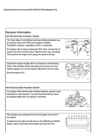
The cylinders are numbered from the front gear cover end of
the engine.
To determine the right and left bank on the QSK38 and QSK50
engine, stand at the rear of the engine and face the front.
JOO-I 0
--~Lqr
tpEtvaus
2 4 6 8 10 12 14 16
---;
RB@@®®®®@@
-
t
lB ®®®®C~®®(s1) '-
1 3 5 7 9 11 13 15
0:J600121
2. When referring to system electronics, a standard cylinder
numbering system has been adopted. This is only used for the
electronic system components on engines with electronically
actuated injectors.
Each cylinder has two rocker levers. When facing the cylinder
head, the rocker lever on the left is the exhaust rocker lever.
The rocker lever on the right is the intake rocker lever.
If the push rods are removed for the service, make sure they
are installed in the same locations.
QSK38 Firing Order:
1R-6L-5R-2L-3R-4L-6R-1 L-2R-5L-4R-3L or 2-11-10-3-6-7-12-1-
4-9-8-5.
RB = Right Bank of cylinders.
LB = Left Bank of cylinders.
QSK50 Firing Order:
1R-1 L-3R-3L-2R-2L-5R-4L-8R-8L-6R-6L-7R-7L-4R-5L or 2-1-6-
5-4-3-10-7-16-15-12-11-14-13-8-9
RB = Right Bank of cylinders.
LB = Left Bank of cylinders.
The normal rotation direction for QSK38 and QSK50 is
clockwise, when viewed from the front of the engine.
Preparatory Steps
with Mechanically Actuated Injector
r
2 4 6 8 10 12
-
® ® @)(4R) ~El@
RS
-
1
,
LB
G!cj ® GD®® (~D I-
'-
~
1 3 5 7 9 11 02600054
2 4 6 B 10 12 14 16
-1
RS@@@@®®@@
lB @@®®®®®Cs1) '-
1 3 5 7 9 11 13 15
03600121
1
3. AWARNINGA
Batteries can emit explosive gases. To reduce the
possibility of personal injury, always ventilate the
compartment before servicing the batteries. To reduce the
possibility of arcing, remove the negative (-) battery cable
first and attach the negative (-) battery cable last.
AWARNINGA
When using a steam cleaner, wear safety glasses or a face
shield, as well as protective clothing. Hot steam can cause
serious personal injury.
• Disconnect the battery cables. See equipment
manufacturer service information.
• Steam clean the engine to prevent dirt from entering the
engine when the valve covers are removed. Refer to
Procedure 000-009 in Section O.
(/qs3/pubsys2/xml/en/procedures/28/28-000-009.html)
• Remove the rocker lever covers. Refer to Procedure 003-
011 in Section 3. (/qs3/pubsys2/xml/en/procedures/28/28-
003-011-tr.html)
with Electronically Actuated Injector
AWARNINGA
Batteries can emit explosive gases. To reduce the
possibility of personal injury, always ventilate the
compartment before servicing the batteries, to reduce the
possibility of arcing, remove the negative H battery cable
first and attach the negative (-) battery cable last.
AWARNINGA
When using a steam cleaner, wear safety glasses or a face
shield, as well as protective clothing. Hot steam can cause
serious personal injury.
• Disconnect the battery cables. See equipment
manufacturer service information.
• Steam clean the engine to prevent dirt from entering the
engine when the valve covers are removed. Refer to
Procedure 000-009 in Section O.
(/qs3/pubsys2/xml/en/procedures/28/28-000-009.html)
• Remove the rocker lever covers. Refer to Procedure 003-
011 in Section 3. (/qs3/pubsys2/xml/en/procedures/28/28-
ckaOOwa
4. 003-011-tr.html)
Adjust
with Mechanically Actuated Injector
r
Valve and injector adjustment marks are in three locations.
Valve and injector adjustment marks are on the vibration
damper. The marks must be aligned with the pointer.
& CAUTION &
When using the starter covers on the right bank, the marks
on the flywheel that begin with an "A" must be used or the
valves and injectors will not be adjusted correctly, causing
damage to the push rods.
For valve and injector adjustment marks on the flywheel, with
the engine barring device located on the right bank of the
engine:
<8 The starter bore cover must be removed to see the marks.
& CAUTION &
When using the starter covers on the left bank, the marks
on the flywheel that begin with a "C" must be used or the
valves and injectors will not be adjusted correctly, causing
damage to the push rods.
For valve and injector adjustment marks on the flywheel, with
the engine barring device located on the left bank of the engine:
<8 The starter bore cover must be removed to see the marks.
This illustration also shows the engine barring device. To use
the device, remove the clip and push the device shaft toward
the flywheel. The barring device must be rotated
counterclockwise to turn the flywheel and crankshaft in the
direction of normal rotation.
,
"
@)
~ 6~"S~
)~ il6iaga :
il61agh
it61agc
1
5. The following is the firing order for ail K38 engines.
• 1R-6L-5R-2L-3R-4L-6R-1 L-2R-5L-4R-3L
Note: Not all K50 engines have the same firing order.
Some engines manufactured after September 1986
have a revised firing order. These engines have decals
on the rocker lever covers and the engine dataplate is
stamped with "REVISED FIRING ORDER".
The following is the standard firing order for all K50 engines
which were manufactured before September 1986.
• 'I R-1 L-3R-3L-7R-7L-5R-5L-8R-8L-6R-6L-2R-2L-4R-4L
The following is the "REVISED FIRING ORDER" used on some
engines built after September, 1986.
• 1R-1 L-3R-3L-2R-2L-5R-4L-8R-8L-6R-6L-7R-7L-4R-5L
Two full engine rotations are required to adjust the valves and
injectors on K38 and K50 engines.
The normal rotation direction for K38 and K50 engines is
clockwise, when viewed from the front of the engine.
The valve set is represented by"VS". Ignore the "TC" (top
center) marks while setting the valves and injectors.
Determine the cylinder in position for valve set:
• The crossheads and valves are ready to be adjusted on
the cylinder that has all the valves closed
• Check the two cylinders shown on the "VS" mark.
Note: The KTA50-G3, KTA50-G4, KTTA50-G2,
K2000E, K1800E, and K1500E engines contain a unique
camshaft that creates a noticeable difference in the
height of the valve adjusting screws. When the valves
are properly adjusted on these engines, the exhaust
valve adjusting screw will have approximately one
thread visible above the top of the lock nut. The intake
valve adjusting screw will have approximately three
threads visible above the top of the adjusting screw.
If the rocker lever assemblies have been removed, use this step
to determine the cylinder to be set.
All adjusting screws must be loose on all cylinders, and the
push rod must remain in alignment.
Perform this step on both cylinders to be checked.
Hold both rocker levers against the crossheads. Turn the
adjusting screws until they touch the push rods. Turn the lock
nuts until they touch the levers.
1
J it600wa
~
,
;:,:~,,:~:~,
:~ ;~®
G~~~ - - I
~ ~- " =,~J
~ _-=--=====- - rh4(X)ub
6. The cylinder with the adjusting screws that are nearly the same
height (intake screw can be up to two threads above the
exhaust) is ready for valve adjustment. The second cylinder that
is not ready for adjustment will have the adjusting screw for the
exhaust valve more than five threads above the intake screw.
The push rods will be close to the same height above the top of
the rocker lever housing on the cylinder ready for valve
adjustment.
& CAUTION &
Use the correct chart for the engine being serviced or the
parts can be damaged.
If the rocker levers have not been removed, wiggle the valve
rocker levers on the two cylinders in question. The crossheads
and valves on the cylinder where both levers feel loose are
ready to adjust.
After identifying the cylinder with the valves ready to be
adjusted, use the following charts for the sequence. The steps
and specifications for adjusting the crossheads, valves, and
injectors follow the charts.
Adjustment can begin on any valve set mark. In the illustration,
assume the 1R-6R or 1R-8R marks are aligned and the
adjusting screw height for the valves on the cylinder number 1
right-bank are closed and ready to adjust.
The following charts give the crosshead, valve, and injector
adjustment sequence. it600wa
~
K38 (Outer Base Circle) Valve and Injector Adjustment Chart
Valves Closed Adjust Valves Adjust Injectors
Valve Set Mark "VS" On Cylinder Number On Cylinder Number On Cylinder Number
(L - Left-Bank) (R- (L - Left-Bank) (R- (L - Left-Bank) (R- (L - Left-Bank) (R-
Right-Bank) Right-Bank) Right-Bank) Right-Bank)
1R-6RVS 1R 1R 2R
6L-1L VS 6L 6L 5L
5R-2RVS 5R 5R 4R
2L-5L VS 2L 2L 3L
3R-4RVS 3R 3R 1R
4L-3L VS 4L 4L 6L
1R-6RVS 6R 6R 5R
7. K38 (Outer Base Circle) Valve and Injector Adjustment Chart
Valves Closed Adjust Valves Adjust Injectors
6L-1L VS 1L 1L 2L
SR-2RVS 2R 2R 3R
2L-SL VS SL SL 4L
3R-4RVS 4R 4R 6R
4L-3L VS 3L 3L 1L
K50 (Outer Base Circle) Valve and Injector Adjustment Chart
Valves Closed Adjust Valves Adjust Injectors
Valve Set Mark "VS" On Cylinder Number On Cylinder Number On Cylinder Number
(L - Left-Bank) (R- (L - Left-Bank) (R- (L - Left-Bank) (R- (L - Left-Bank) (R-
Right-Bank) Right-Bank) Right-Bank) Right-Bank)
1R-8R VS 1R 1R 6R
1L-8L VS 1L 1L 6L
3R-6R VS 3R 3R 2R
3L-6L VS 3L 3L 2L
2R-7R VS 7R 7R 4R
2L-7L VS 7L 7L 4L
4R-SRVS SR SR 1R
4L-SL VS SL SL 1L
1R-8R VS 8R 8R 3R
1L-8L VS 8L 8L 3L
3R-6R VS 6R 6R 7R
3L-6L VS 6L 6L 7L
2R-7R VS 2R 2R SR
2L-7L VS 2L 2L SL
4R-SRVS 4R 4R 8R
4L-SL VS 4L 4L 8L
Note: For K50 STC and Hydraulic Variable Timing engines, it is important to know if the
engine has the standard firing order or the revised firing order. Do not use the standard
firing order sequence for uprate engines manufactured after September, 1986, that have
the revised firing order. All engines that have the "REVISED FIRING ORDER" have
STC or Hydraulic Variable Timing injectors and are identified as revised on the engine
dataplate. These engines also have decals on the rocker lever covers.
K50 (Outer Base Circle) Revised Firing Order with STC or Hydraulic Variable Timing Valve
and Injector Adjustment Chart
Valves Closed Adjust Valves Adjust Injectors
Valve Set Mark "VS" On Cylinder Number On Cylinder Number On Cylinder Number
(L - Left-Bank) (R- (L - Left-Bank) (R- (L - Left-Bank) (R- (L - Left-Bank) (R-
Right-Bank) Right-Bank) Right-Bank) Right-Bank)
1R-8R VS 1R 1R 6R
8. K50 (Outer Base Circle) Revised firing Order with STC or Hydraulic Variable Timing Valve
and Injector Adjustment Chart
Valves Closed Adjust Valves Adjust Injectors
1L-8L VS 1L 1L 6L
3R-6RVS 3R 3R 7R
3L-6L VS 3L 3L 7L
2R-7RVS 2R 2R 4R
2L-7L VS 2L 2L 5L
4R-5RVS 5R 5R 1R
4L-5L VS 4L 4L 1L
1R-8RVS 8R 8R 3R
1L-8L VS 8L 8L 3L
3R-6RVS 6R 6R 2R
3L-6L VS 6L 6L 2L
2R-7RVS 7R 7R 5R
2L-7L VS 7L 7L 4L
4R-5RVS 4R 4R 8R
4L-5L VS 5L 5L 8L
Note: Some engines have guideless crossheads and
;~~~ e-
t?/ k-
do not require adjustment.
Note: Crosshead adjustment must always be made
before attempting to adjust the valves. ~f x '-~'~~~~&~"
(~~xJi1~~~ II,Q)j
~ ,r=" /;cE,~
Adjust the crossheads on the cylinder that has both valves
~~~
closed. ~~~ . ~t;:l:; """'"
Loosen the crosshead adjusting screw lock nuts on the intake
and exhaust valve crossheads.
Use the following procedure to adjust both the intake and I~~ Ii" /11'
;~~
exhaust crossheads. lJf ~ ~f
Turn the adjusting screw out at least one turn. . / ) I l~ ~ ,JY Ji:-
Hold the crosshead down against its guide. =~,' ~ r; j
Turn the adjusting screw in until it touches the top of the valve ~~~ ~ :--'<~;:
rh4cbllb
stem, but does not raise the crosshead.
Hold the adjusting screw in this position. The adjusting screw ~~II I~~~
'Ch8'~ "='
must not turn when the lock nut is tightened to its torque value. .~ ' ~I: .:1
" ;(, """
Tighten the lock nut. The following torque values are given with
~ir
~.~..
and without torque wrench adapter (1). Part Number 3163196.
'::.;; r::;
~~
Torque Value: J0
With Adapter 35 n-m [ 26 ft-Ib]
-2b
9. Torque Value:
Without Adapter 40 n-m [ 30 ft-Ib ]
Valve Adjustment
mm in
0.69 Exhaust 0.027
0.36 Intake 0.014
Select a feeler gauge for the correct valve lash specification.
Use service tool, Part Number 3163171 (intake) or Part Number
3163172 (exhaust). Insert the gauge (2) between the rocker
lever and the crosshead.
Two different methods for establishing valve lash clearance are
described below. Either method can be used; however, the
torque wrench method has proven to be the most consistent.
• Torque Wrench Method: Use an inch pound torque wrench,
Part Number 3376592, and tighten the adjusting screw.
Torque Value: 0.68 n·m [ 6 in-Ib ]
• Feeler Gauge Method: Use a screwdriver and turn the
adjusting screw only until the lever touches the feeler
gauge.
The adjusting screw must not turn when the lock nut is
tightened.
Tighten the lock nut to the value indicated below.
Torque Value:
With Adapter 45 n·m [ 33 ft-Ib ]
Torque Value:
Without Adapter 60 n-m [ 44 ft-Ib ]
The feeler gauge must slide backward and forward with only a
small amount of drag.
Attempt to insert a feeler gauge that is 0.03 mm [0.001 in]
thicker. The valve lash is not correct when the thicker gauge
will fit.
0.36 mm
I [0.014 in]
rh~CCL;d
~
.
~
)~~
m~
mmmm j
( rh6lQua
f~ .
"'1£ -'>
):~ .. -~~
: ( r
'c:L-m------R~ n ~
-------~-= I J......-..~Ul
10. Repeat the adjustment process until the clearance is correct on
both the intake and exhaust valves for the cylinder being
adjusted.
Note: The torque wrench must be calibrated, have a
resolution of 0.28 N-m [2.5 in-Ib], and have a range of 17
to 23 N-m [150 to 204 in-Ib]. Do not use a clicker-type
torque wrench.
Use a dial type torque wrench to tighten the injector rocker lever
adjusting screw. If the screw causes chattering during setting,
repair the screw and lever as required.
Hold the torque wrench in a position that allows you to look in a
direct line at the dial. This is to make sure the dial will be read
accurately.
Tighten the adjusting screw to make sure the parts are in
alignment and to squeeze the oil out of the valve train.
Torque Value: 11 n-m [ 97 in-Ib ]
Loosen the adjusting screw at least one turn.
Tighten the adjusting screw.
Torque Value: 10 n-m [ 89 in-Ib ]
Hold the adjusting screw in this position. The adjusting screws
must not turn when the lock nut is tightened.
Tighten the lock nut.
Torque Value:
With Adapter 45 n-m [ 33 ft-Ib ]
Torque Value:
Without Adapter 60 n-m [ 44 ft-Ib ]
If the barring device was used, allow the spring to push the
shaft and clear the ring gear.
Install the clip.
with Electronically Actuated Injector
Note: The following procedure applies to the QSK38
MCRS engine.
09600095
11. If the rocker lever assemblies have been removed, complete
the following list on both cylinders:
• Lubricate the adjusting screw threads with clean engine oil
prior to making valve and injector adjustments.
• All adjusting screws must be loose on all cylinders, and the
pushrods must remain in alignment.
• Hold both rocker levers against the crossheads. Turn the
adjusting screws until they touch the pushrods. Turn the
locknuts until they touch the levers.
• The pushrods will be close to the same height above the
top of the rocker lever housing on the cylinder that is ready
for adjustment.
• The number of threads visible above the adjusting nut will
not be the same. There will be more threads visible on the
intake adjusting screw than on the exhaust.
The QSK38 engine has valve adjustment marks on the
vibration damper and on both sides of the flywheel housing.
Valve adjustment marks must be aligned with the pointer. If
not, a false adjustment can occur.
One pair of valves is adjusted at each pulley index mark, before
rotating the engine to the next index mark.
Two crankshaft revolutions are required to adjust all of the
valves.
& CAUTION &
When using the starter covers on the right bank, the marks
on the flywheel that begin with an A must be used or the J
valves will not be adjusted correctly, causing damage to
the engine.
When using the valve adjustment marks on the flywheel, the
upper starter bore cover must be removed to see the marks.
The A marks must be used if the marks are viewed on the right
bank.
The C marks must be used if the marks are viewed on the left
bank.
& CAUTION &
When using the starter covers on the left bank, the marks
on the flywheel that begin with a C must be used or the
valves will not be adjusted correctly, causing damage to
il6iagf
il61agh
12. the engine.
This illustration shows the engine barring device. To use the
device, remove the clip and push the device shaft toward the
flywheel. The barring device must be rotated
counterclockwise to turn the flywheel and crankshaft in the
direction of normal rotation.
VS represents the valve set. Ignore any TC (top center) marks
while setting the valves.
Determine the cylinder in position for valve set:
The valves are ready to be adjusted on the cylinder that has all
of the valves closed.
Note: When all of the valves are closed, there is some
movement in the rocker levers.
Check the two cylinders shown on the VS mark.
If the rocker levers have not been removed, wiggle the valve
rocker levers on the two cylinders in question. Set the valves on
the cylinder where both levers feel loose.
Adjustment can begin on any valve set mark.
Use the following chart as a worksheet to keep track of where
you are in the valve set procedure.
QSK38 Outer Base Circle Valve Set
VS Mark
Valves Closed on Cylinder
Number
1R-6RVS 1R (2)
6L-1L VS 6L (11)
5R-2RVS 5R (10)
2L-5L VS 2L (3)
3R-4RVS 3R (6)
4L-3L VS 4L (7)
1R-6RVS 6R (12)
6L-1L VS 1L (1)
5R-2RVS 2R (4)
it6!agc
il61agh
Adjust Valves on Cylinder
Number
1R (2)
6L(11)
5R (10)
2L (3)
3R (6)
4L (7)
6R (12)
1L (1)
2R (4)
13. QSK38 Outer Base Circle Valve Set
VS Mark
Valves Closed on Cylinder
Number
2L-5L VS
3R-4RVS
4L-3L VS
Exhaust
Valves
(A)
Intake
Valves
(8)
5L (9)
4R (8)
3L (5)
Valve Clearances
mm in
0.69 MAX 0.027
0.36 MAX 0.014
There are two different methods used to set valve lash
clearance: Torque Wrench Method and Feeler Gauge Method;
both are described below. Either method can be used.
However, the torque wrench method has proven to be the most
consistent.
Make sure the crossheads are firmly in place on the valve
stems.
Select the proper feeler gauge for the valves being set. Use
service tool, Part Number 3163171 (intake) or 3163172
(exhaust).
Make sure the feeler gauge is under the center of the ball-and-
socket, or the socket can rock or tip, resulting in an incorrect
adjustment. Hold the swivel foot flat when checking the lash to
avoid false readings.
The adjustment screws must turn freely, or a false reading or
setting can occur.
Valve Adjustment - Torque Wrench Method
Make sure the parts are aligned, and squeeze the oil out of the
valve train by tightening the adjusting screw.
Loosen the adjusting screw at least one revolution.
Insert the feeler gauge between the rocker lever socket and the
crosshead.
Use torque wrench, Part Number 3376592, and tighten the
adjusting screw.
Adjust Valves on Cylinder
Number
5L (9)
4R (8)
3L (5)
14. Torque Value: 0.68 n-m [ 6 in-Ib ]
Remove the feeler gauge.
The adjusting screw must not turn when the locknut is
tightened. locknut torque can be applied with or without torque
wrench adapter, Part Number 3163196.
Tighten the locknut.
Torque Value:
With Adapter 48 n-m [ 35 ft-Ib ]
Torque Value:
Without Adapter 60 n-m [ 44 ft-Ib ]
Attempt to insert a feeler gauge that is 0.03-mm [0.001-in]
thicker. The valve lash is not correct if the thicker feeler gauge
will fit.
Repeat the adjustment process until the proper lash is
obtained.
Valve Adjustment - Feeler Gauge Method
Make sure parts are aligned, and squeeze the oil out of the
valve and injector train by tightening the adjusting screw.
loosen the adjusting screw at least one revolution.
Insert the feeler gauge between the rocker lever socket and the
crosshead.
Tighten the adjusting screw until the rocker lever touches the
feeler gauge.
The adjusting screw must not turn when the locknut is
tightened. locknut torque can be applied with or without a
torque wrench adapter, Part Number 3163196.
Tighten the locknut.
Torque Value:
With Adapter 48 n-m [ 35 ft-Ib ]
Torque Value:
Without Adapter 60 n-m [ 44 ft-Ib ]
Attempt to insert a feeler gauge that is 0.03-mm [0.001-in]
thicker. The valve lash is not correct if the thicker feeler gauge
will fit.
Repeat the adjustment process until the proper lash is
obtained.
c- ,
00000122
15. with Electronically Actuated Injector
r
Note: The following procedure applies to the QSK50
MCRS engine.
& CAUTION &
To reduce the possibility of engine damage, use a cylinder
head protective cover to prevent tools from falling into the
cam follower cavity.
Install the cylinder head protective cover, Part Number
4918282, into the push tube hole.
This illustration shows the engine barring device. To use the
device, remove the clip and push the device shaft toward the
flywheel. The barring device must be rotated
counterclockwise to turn the flywheel and crankshaft in the
direction of normal rotation.
The 'I R8R VS mark represents valve set location for cylinder 1
or 8 on the right bank. This mark will be used to set the valves
on engines with electronically actuated injectors. This will allow
all valves to be set in two positions.
Push the shaft in and rotate the barring device until the 1R8R
VS mark on the pulley is aligned with the mark that is cast into
the boss for the accessory drive seal on the front gear cover.
The number of threads visible above the adjusting nut will not
be the same. There will be more threads visible on the intake
adjusting screw than on the exhaust adjusting screw.
If the rocker lever assemblies have been removed, use this step
to determine the cylinder to be set.
All adjusting screws must be loose on all cylinders, and the
push rods must remain in alignment.
Perform this step on both cylinders to be checked.
Hold both rocker levers against the crossheads. Turn the
adjusting screws in until they touch the push rods. Turn the
locknuts until they touch the levers.
The push rods will be the same height above the top of the
rocker lever housing on the valves that should be loose.
•
eo ~22400276
i!6lagc
1
16. If both number 1 cylinder rocker levers on the right bank are
loose, proceed to the next step. If the number 1 cylinder rocker
levers on the right bank are not loose, rotate the crankshaft 360
degrees and proceed to the next step.
If the number 1 cylinder on the right bank is at 1R8R VS and
both rocker levers are loose, the valve lash (overhead set) can
be checked on the following rocker levers:
Intake Exhaust
1R (2) 1R (2)
4R (8) 2R (4)
6R (12) 3R (6)
7R (14) 4R (8)
5L (9) 1L (1)
6L (11) 3L (5)
7L (13) 5L (9)
8L (15) 7L (13)
Valve Adjustment
mm in
Exhaust
Valves 0.69 MAX 0.027
(A)
Intake
Valves 0.36 MAX 0.014
(8)
Use service tool, Part Number 3163171 (intake) or Part Number
3163172 (exhaust). Select a feeler gauge for the correct valve
lash specification. Insert the feeler gauge between the rocker
lever socket and the crosshead.
Make certain the crossheads are firmly in place on the valve
stem tips.
Make certain the feeler gauge is under the center of the ball
and socket or the socket can rock or tip, resulting in an incorrect
adjustment. To avoid false readings, hold the swivel foot to
avoid binding while checking the valve lash.
Two different methods for establishing valve lash clearance are
discribed below:
.. Torque Wrench Method - use Part Number 3376592, inch-
pound torque wrench to tighten the adjustment screw to
c- ,
00400164
17. 0.68 N-m [6 in-Ib] torque against the feeler gauge.
• Feeler Gauge Method - use a flathead screw driver and
turn the adjusting screw only until the lever touches the
feeler gauge.
Either method can be used. The torque wrench method has
proven to be the most consistent.
To set the valves using the torque wrench method, complete
the following steps:
1. Be certain the parts are in alignment, Tighten the
adjustment screw and squeeze the oil out of the valve
train.
2. Loosen the adjustment screw at least one revolution.
3. Insert the feeler gauge between the rocker lever socket
and the crosshead.
4. Use torque wrench, Part Number 3376592, and tighten the
adjustment screw.
5. Remove the feeler gauge.
Torque Value: 0.68 n-m [ 6 in-Ib ]
To set the valves using the feeler gauge method, complete the
following steps:
1. Make sure parts are aligned, and squeeze the oil out of the
valve and injector train by tightening the adjusting screw.
2. Loosen the adjusting screw at least one revolution.
3. Insert the feeler gauge between the rocker lever socket
and the crosshead.
4. Tighten the adjusting screw until the rocker lever touches
the feeler gauge.
The adjustment screw must not turn when the locknut is
tightened. Locknut torque can be applied with or without a
torque wrench adapter, Part Number 3163196.
Tighten the locknut.
For the torque method (with adapter), use torque wrench
adapter, Part Number ST-669.
Torque Value:
With Adapter 48 n-m [ 35 ft-Ib ]
Torque Value:
Without Adapter 60 n-m [ 44 ft-Ib ]
Attempt to insert a feeler gauge that is 0.03 mm [0.001 in]
thicker than the valve lash specification. The lash is not correct
when the thicker gauge will 'fit.
18. Repeat the adjustment process until the proper clearance is
obtained.
Use the barring tool to rotate the crankshaft 360 degrees. Use
the previous steps and specifications to set the valve lash on
the following rocker levers:
Intake Exhaust
2R (4) 5R (10)
3R (6) 6R (12)
5R (10) 7R (14)
8R (16) 8R (16)
1L (1) 2L (3)
2L (3) 4L (7)
3L (5) 6L (11)
4L (7) 8L (15)
Remove the cylinder head protective cover, Part Number
4918282, from the push tube hole.
Finishing Steps
with Mechanically Actuated Injector
&WARNING&
Batteries can emit explosive gases. To reduce the
possibility of personal injury, always ventilate the
compartment before servicing the batteries. To reduce the
possibility of arcing, remove the negative (-) battery cable
first and attach the negative (-) battery cable last.
• Install the rocker lever cover. Refer to Procedure 003-011
in Section 3. (/qs3/pubsys2/xml/en/procedures/28/28-003-
011-tr.html)
• Connect the battery cables. See equipment manufacturer
service information.
• Operate the engine and check for proper operation.
®
~
~,,~~
o ~"~ ~~~~:~
~~~w:
~~~~ ~.
~_~~ "'l:II"11 0 22400276
ckeOOwfJ
19. with Electronically Actuated Injector
AWARNINGA
Depending on the circumstance, fuel is flammable. Keep
all cigarettes, flames, pilot lights, arcing equipment, and
switches out of the work area and areas sharing
ventilation to reduce the possibility of severe personal
injury or death when working on the fuel system.
AWARNINGA
Batteries can emit explosive gases. To reduce the
possibility of personal injury, always ventilate the
compartment before servicing the batteries, to reduce the
possibility of arcing, remove the negative (-) battery cable
first and attach the negative (-) battery cable last.
• Install the rocker lever covers. Refer to Procedure 003-011
in Section 3 (/qs3/pubsys2/xml/en/procedures/28/28-003-
011-tr.html)
• Install the high pressure injector supply lines. Refer to
Procedure 006-051 in Section 6.
(/qs3/pubsys2/xml/en/procedures/28/28-006-051-tr.html)
• Connect the battery cables. See equipment manufacturer
service information.
• Operate the engine and check for proper operation.
last Modified: 01..Jun-2015