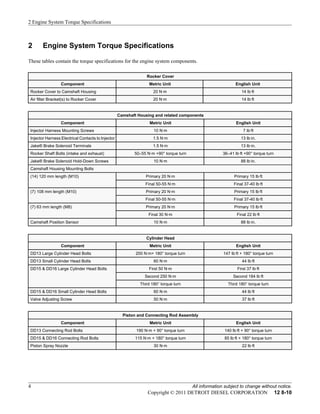
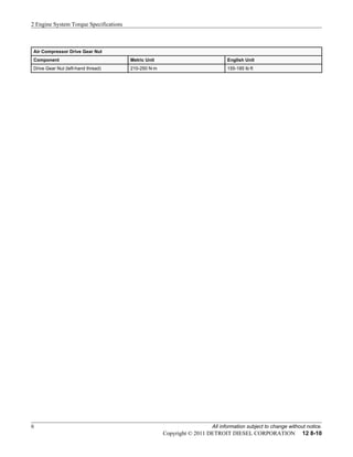
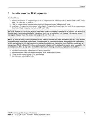
1 12 8-10
SUBJECT DATE
Air Compressor Drive Gear Nut Torque December 2010
Additions, Revisions, or Updates
Publication Number / Title Platform Section Title Change
DDC-SVC-MAN-0080
DD
Specifications
Information about the air compressor drive gear nut torque is added
to this procedure.DDC-SVC-MAN-0081 41.4 Installation of the Air
Compressor
12 08-10
All information subject to change without notice. 3
12 8-10 Copyright © 2011 DETROIT DIESEL CORPORATION
2 Engine System Torque Specifications
These tables contain the torque specifications for the engine system components.
Rocker Cover
Component Metric Unit English Unit
Rocker Cover to Camshaft Housing 20 N·m 14 lb·ft
Air filter Bracket(s) to Rocker Cover 20 N·m 14 lb·ft
Camshaft Housing and related components
Component Metric Unit English Unit
Injector Harness Mounting Screws 10 N·m 7 lb·ft
Injector Harness Electrical Contacts to Injector 1.5 N·m 13 lb·in.
Jake® Brake Solenoid Terminals 1.5 N·m 13 lb·in.
Rocker Shaft Bolts (intake and exhaust) 50–55 N·m +90° torque turn 36–41 lb·ft +90° torque turn
Jake® Brake Solenoid Hold-Down Screws 10 N·m 88 lb·in.
Camshaft Housing Mounting Bolts
(14) 120 mm length (M10) Primary 20 N·m Primary 15 lb·ft
Final 50-55 N·m Final 37-40 lb·ft
(7) 108 mm length (M10) Primary 20 N·m Primary 15 lb·ft
Final 50-55 N·m Final 37-40 lb·ft
(7) 63 mm length (M8) Primary 20 N·m Primary 15 lb·ft
Final 30 N·m Final 22 lb·ft
Camshaft Position Sensor 10 N·m 88 lb·in.
Cylinder Head
Component Metric Unit English Unit
DD13 Large Cylinder Head Bolts 200 N·m+ 180° torque turn 147 lb·ft + 180° torque turn
DD13 Small Cylinder Head Bolts 60 N·m 44 lb·ft
DD15 & DD16 Large Cylinder Head Bolts First 50 N·m First 37 lb·ft
Second 250 N·m Second 184 lb·ft
Third 180° torque turn Third 180° torque turn
DD15 & DD16 Small Cylinder Head Bolts 60 N·m 44 lb·ft
Valve Adjusting Screw 50 N·m 37 lb·ft
Piston and Connecting Rod Assembly
Component Metric Unit English Unit
DD13 Connecting Rod Bolts 190 N·m + 90° torque turn 140 lb·ft + 90° torque turn
DD15 & DD16 Connecting Rod Bolts 115 N·m + 180° torque turn 85 lb·ft + 180° torque turn
Piston Spray Nozzle 30 N·m 22 lb·ft
2 Engine System Torque Specifications
4 All information subject to change without notice.
Copyright © 2011 DETROIT DIESEL CORPORATION 12 8-10
Crankshaft
Component Metric Unit English Unit
DD13 Main Bearing Cap Bolts First 50 N·m First 36 lb·ft
Second 150 N·m Second 110 lb·ft
Third 300 N·m Third 221 lb·ft
Fourth 90° torque turn Fourth 90° torque turn
DD15 Main Bearing Cap Bolts First 50 N·m First 36 lb·ft
Second 150 N·m Second 110 lb·ft
Third 250 N·m Third 184 lb·ft
Fourth 90° torque turn Fourth 90° torque turn
Fifth 90° torque turn Fifth 90° torque turn
Vibration Damper Pulley 200 N·m 147.5 lb·ft
Flywheel and Flywheel Housing
Component Metric Unit English Unit
Flywheel Bolts 200-220 N·m + 90° to 100° torque turn 147-162 lb·ft + 90° to 100° torque turn
Flywheel Housing Bolts
M8 x 16 (2 Qty) 30 N·m 22 lb·ft
M14 x 1.5 x 90 120 N·m 88 lb·ft
M10 x 45 (6 Qty) 60 N·m 44 lb·ft
M10 x 90 (3 Qty) 60 N·m 44 lb·ft
M14 x 1.5 x 180 (1 Qty) 120 N·m 88 lb·ft
M8 x 45 (2 Qty) 30 N·m 22 lb·ft
M8 x 30 (2 Qty) 30 N·m 22 lb·ft
M14 x 1.5 x 70 (1 Qty) 120 N·m 88 lb·ft
M12-10 (1 Qty) 100 N·m 74 lb·ft
Engine Mounted Radiator Support
Component Metric Unit English Unit
Engine Mounted Radiator Support Bolts 250 N·m 184 lb·ft
Engine Lifter Brackets
Component Metric Unit English Unit
Rear Lifter Bracket 180 N·m 132 lb·ft
Venturi Pipe to Front Crossover Tube Lifter
Bracket
30 N·m 22 lb·ft
Coolant Delivery Pipe to Front Crossover Tube
Lifter Bracket
30 N·m 22 lb·ft
Belt Drive Tensioner
Component Metric Unit English Unit
Maximum Allowable Torque 60 N·m 44 lb·ft
12 08-10
All information subject to change without notice. 5
12 8-10 Copyright © 2011 DETROIT DIESEL CORPORATION
Air Compressor Drive Gear Nut
Component Metric Unit English Unit
Drive Gear Nut (left-hand thread) 210-250 N·m 155-185 lb·ft
2 Engine System Torque Specifications
6 All information subject to change without notice.
Copyright © 2011 DETROIT DIESEL CORPORATION 12 8-10
3 Installation of the Air Compressor
Install as follows:
1. If removed, install the air compressor gear to the air compressor shaft and secure with nut. Thread is left-handed; torque
nut to 210-250 N·m (155-185 lb·ft).
2. Clean all foreign material from the mating surfaces of the air compressor and the cylinder block.
3. Install a new O-ring on the air compressor hub and a new O-ring on the oil supply, and then install the air compressor on
the cylinder block. Torque the four bolts to 60 N·m (44 lb·ft).
NOTICE: Ensure the correct bolt length is used when the air compressor is installed. If an incorrect bolt length (too
long) is used, the cup plugs installed in the cylinder block can be pushed out into the gear train causing severe
damage to the gear train. The correct bolt length is 35 mm (1.37 in.).
NOTICE: Ensure when the air compressor coolant lines are installed that there is an O-ring and an O-ring retainer
installed on both ends of the coolant lines. Ensure that the air compressor retainer is installed on the coolant line
and is pushed down to lock the lines onto the inlet and outlet ports to the cylinder block, fuel filter module and air
compressor. A leak will occur if the lines are incorrectly installed and the coolant line retainer is not engaged in the
locked position. If the O-ring or the coolant line retainers are missing or removed, replace the coolant line.
4. Install the coolant supply and return lines to the air compressor.
5. Install the air lines to and from the air compressor. Refer to OEM specifications.
6. Fill the cooling system. Refer to OEM specifications.
7. Start the engine and check for leaks.
12 08-10
All information subject to change without notice. 7
12 8-10 Copyright © 2011 DETROIT DIESEL CORPORATION

Dd15 engine torque spec

  • 1.
    1 12 8-10 SUBJECTDATE Air Compressor Drive Gear Nut Torque December 2010 Additions, Revisions, or Updates Publication Number / Title Platform Section Title Change DDC-SVC-MAN-0080 DD Specifications Information about the air compressor drive gear nut torque is added to this procedure.DDC-SVC-MAN-0081 41.4 Installation of the Air Compressor 12 08-10 All information subject to change without notice. 3 12 8-10 Copyright © 2011 DETROIT DIESEL CORPORATION
  • 2.
    2 Engine SystemTorque Specifications These tables contain the torque specifications for the engine system components. Rocker Cover Component Metric Unit English Unit Rocker Cover to Camshaft Housing 20 N·m 14 lb·ft Air filter Bracket(s) to Rocker Cover 20 N·m 14 lb·ft Camshaft Housing and related components Component Metric Unit English Unit Injector Harness Mounting Screws 10 N·m 7 lb·ft Injector Harness Electrical Contacts to Injector 1.5 N·m 13 lb·in. Jake® Brake Solenoid Terminals 1.5 N·m 13 lb·in. Rocker Shaft Bolts (intake and exhaust) 50–55 N·m +90° torque turn 36–41 lb·ft +90° torque turn Jake® Brake Solenoid Hold-Down Screws 10 N·m 88 lb·in. Camshaft Housing Mounting Bolts (14) 120 mm length (M10) Primary 20 N·m Primary 15 lb·ft Final 50-55 N·m Final 37-40 lb·ft (7) 108 mm length (M10) Primary 20 N·m Primary 15 lb·ft Final 50-55 N·m Final 37-40 lb·ft (7) 63 mm length (M8) Primary 20 N·m Primary 15 lb·ft Final 30 N·m Final 22 lb·ft Camshaft Position Sensor 10 N·m 88 lb·in. Cylinder Head Component Metric Unit English Unit DD13 Large Cylinder Head Bolts 200 N·m+ 180° torque turn 147 lb·ft + 180° torque turn DD13 Small Cylinder Head Bolts 60 N·m 44 lb·ft DD15 & DD16 Large Cylinder Head Bolts First 50 N·m First 37 lb·ft Second 250 N·m Second 184 lb·ft Third 180° torque turn Third 180° torque turn DD15 & DD16 Small Cylinder Head Bolts 60 N·m 44 lb·ft Valve Adjusting Screw 50 N·m 37 lb·ft Piston and Connecting Rod Assembly Component Metric Unit English Unit DD13 Connecting Rod Bolts 190 N·m + 90° torque turn 140 lb·ft + 90° torque turn DD15 & DD16 Connecting Rod Bolts 115 N·m + 180° torque turn 85 lb·ft + 180° torque turn Piston Spray Nozzle 30 N·m 22 lb·ft 2 Engine System Torque Specifications 4 All information subject to change without notice. Copyright © 2011 DETROIT DIESEL CORPORATION 12 8-10
  • 3.
    Crankshaft Component Metric UnitEnglish Unit DD13 Main Bearing Cap Bolts First 50 N·m First 36 lb·ft Second 150 N·m Second 110 lb·ft Third 300 N·m Third 221 lb·ft Fourth 90° torque turn Fourth 90° torque turn DD15 Main Bearing Cap Bolts First 50 N·m First 36 lb·ft Second 150 N·m Second 110 lb·ft Third 250 N·m Third 184 lb·ft Fourth 90° torque turn Fourth 90° torque turn Fifth 90° torque turn Fifth 90° torque turn Vibration Damper Pulley 200 N·m 147.5 lb·ft Flywheel and Flywheel Housing Component Metric Unit English Unit Flywheel Bolts 200-220 N·m + 90° to 100° torque turn 147-162 lb·ft + 90° to 100° torque turn Flywheel Housing Bolts M8 x 16 (2 Qty) 30 N·m 22 lb·ft M14 x 1.5 x 90 120 N·m 88 lb·ft M10 x 45 (6 Qty) 60 N·m 44 lb·ft M10 x 90 (3 Qty) 60 N·m 44 lb·ft M14 x 1.5 x 180 (1 Qty) 120 N·m 88 lb·ft M8 x 45 (2 Qty) 30 N·m 22 lb·ft M8 x 30 (2 Qty) 30 N·m 22 lb·ft M14 x 1.5 x 70 (1 Qty) 120 N·m 88 lb·ft M12-10 (1 Qty) 100 N·m 74 lb·ft Engine Mounted Radiator Support Component Metric Unit English Unit Engine Mounted Radiator Support Bolts 250 N·m 184 lb·ft Engine Lifter Brackets Component Metric Unit English Unit Rear Lifter Bracket 180 N·m 132 lb·ft Venturi Pipe to Front Crossover Tube Lifter Bracket 30 N·m 22 lb·ft Coolant Delivery Pipe to Front Crossover Tube Lifter Bracket 30 N·m 22 lb·ft Belt Drive Tensioner Component Metric Unit English Unit Maximum Allowable Torque 60 N·m 44 lb·ft 12 08-10 All information subject to change without notice. 5 12 8-10 Copyright © 2011 DETROIT DIESEL CORPORATION
  • 4.
    Air Compressor DriveGear Nut Component Metric Unit English Unit Drive Gear Nut (left-hand thread) 210-250 N·m 155-185 lb·ft 2 Engine System Torque Specifications 6 All information subject to change without notice. Copyright © 2011 DETROIT DIESEL CORPORATION 12 8-10
  • 5.
    3 Installation ofthe Air Compressor Install as follows: 1. If removed, install the air compressor gear to the air compressor shaft and secure with nut. Thread is left-handed; torque nut to 210-250 N·m (155-185 lb·ft). 2. Clean all foreign material from the mating surfaces of the air compressor and the cylinder block. 3. Install a new O-ring on the air compressor hub and a new O-ring on the oil supply, and then install the air compressor on the cylinder block. Torque the four bolts to 60 N·m (44 lb·ft). NOTICE: Ensure the correct bolt length is used when the air compressor is installed. If an incorrect bolt length (too long) is used, the cup plugs installed in the cylinder block can be pushed out into the gear train causing severe damage to the gear train. The correct bolt length is 35 mm (1.37 in.). NOTICE: Ensure when the air compressor coolant lines are installed that there is an O-ring and an O-ring retainer installed on both ends of the coolant lines. Ensure that the air compressor retainer is installed on the coolant line and is pushed down to lock the lines onto the inlet and outlet ports to the cylinder block, fuel filter module and air compressor. A leak will occur if the lines are incorrectly installed and the coolant line retainer is not engaged in the locked position. If the O-ring or the coolant line retainers are missing or removed, replace the coolant line. 4. Install the coolant supply and return lines to the air compressor. 5. Install the air lines to and from the air compressor. Refer to OEM specifications. 6. Fill the cooling system. Refer to OEM specifications. 7. Start the engine and check for leaks. 12 08-10 All information subject to change without notice. 7 12 8-10 Copyright © 2011 DETROIT DIESEL CORPORATION