1. 1. STC
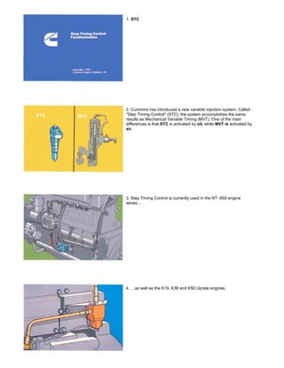
2. Cummins has introduced a new variable injection system. Called
"Step Timing Control" (STC), the system accomplishes the same
results as Mechanical Variable Timing (MVT). One of the main
differences is that STC is activated by oil, while MVT is activated by
air.
3. Step Timing Control is currently used in the NT -855 engine
series...
4. …as well as the K19, K38 and K50 Uprate engines.
2. 5. Although some STC components in these engine series are
different, the operating principles are the same.
6. STC allows the engine to operate in the ADVANCED mode of
injection timing during starting and light engine load conditions, and at
NORMAL timing during medium to high engine load conditions.
7. ADVANCED timing means that fuel is injected earlier in the
compression cycle. NORMAL timing means that fuel is injected later
in the compression cycle.
8. One major reason we must be able to vary injection timing is the
EPA's strict exhaust emission laws. Currently, these laws allow a
maximum of six grams per brake horsepower per hour of
hydrocarbons and nitrogen oxides combined. Of this total, a
maximum of one gram per brake horsepower per hour of
hydrocarbons is allowed. The California engine must also meet
federal legal requirements of 20% opacity acceleration smoke.
3. 9. STC offers many advantages. During ADVANCED injection timing,
it:
improves cold-weather idling characteristics
reduces cold-weather white smoke
improves light-load fuel economy
reduces injector carboning
10. During NORMAL injection timing, STC: .controls cylinder
pressures .reduces nitrogen oxide emissions
11. As a piston moves upward on its compression stroke, the
pressure in the cylinder increases. When fuel is introduced and
begins to burn, the pressure increases to a predetermined maximum.
12. On a given engine, the amount of fuel introduced, and when it is
introduced, determines the point at which peak pressure occurs, and
the value of that pressure.
4. 13. At a given RPM and quantity of fuel, injection timing determines
cylinder pressure. Notice that the point of peak pressure can be
moved by changing the point at which fuel begins to enter the
combustion chamber.
14. Changing the point of peak pressure -and the degree of pressure
-is accomplished with a Step- Timing device. Notice that Step Timing
causes fuel to be injected later than under the same conditions
without this device. The peak pressure is lowered, allowing the
engine to live longer.
15. Step Timing changes the timing from advanced to normal at a
certified switching pressure. This pressure occurs between light and
medium engine loads.
16. During cold start-up and warm idle conditions, only a small
amount of fuel is metered into the injector cup.
5. 17. This low volume of fuel results in later injection, which affects
cylinder pressure. At the top is the advanced condition with Step
Timing, which in- creases cylinder pressures during low-speed, light-
load conditions.
18. At idle, the plunger moves downward at a relatively slow rate.
Consequently, the fuel is not forced through the spray holes hard
enough to attain good atomization.
19. Let's assume that the ambient air temperature is below freezing.
Until this air is sufficiently heated by the aftercooler(s}, it will not allow
the combustion chamber to become hot enough to support good
combustion.
20. So we have two negative factors: fuel that is not atomized enough
to burn thoroughly, and intake air that not only cannot support good
combustion, but continuously cools the piston, liner, valves and
cylinder head.
6. 21. The cold air is compressed, resulting in enough heat to burn only
part of the fuel...usually the finely atomized droplets, and the outer
portions of the larger droplets.
22. These conditions cause white smoke, soot and carbon. White
smoke is formed by raw fuel and air. Soot and carbon are the results
of partially burned fuel.
23. All of this brings us back to Step Timing Control. This hardware
allows the engine to operate at ADVANCED injection timing during
cold-starting and warm-idle conditions, and at NORMAL timing during
medium to high engine load conditions.
24. During ADVANCED injection timing, fuel is injected into the
cylinder sooner. Ignition delay is longer under these conditions, giving
the fuel more time to mix with the intake air. Thus, when ignition
occurs, the fuel is burned more completely. The combustion
temperature is higher, and the cylinder pressure is greater.
7. 25. So, controlling the pressure, that is, reducing it, means that we
can put more air and fuel into the cylinder. This condition results in
more power with- out sacrificing engine durability.
26. Well, we know what STC does...now let's find out how it operates.
To begin our discussion, let's briefly review
27. the injection cycle, using a OFF Top Stop injector and starting
with fuel being metered into the injector cup.
28. When the camfollower roller is on the inner base circle of the
cam, the injector plunger is at the top of its travel. The metering
orifice is uncovered, and fuel flows into the cup.
8. 29. As the camfollower roller moves up the cam injection ramp, onto
the outer base circle, the metering orifice closes; fuel metering ends,
and the plunger seats in the cup, forcing fuel into the cylinder. During
this time the drain port is uncovered, allowing fuel to flow from the
drain groove and return to the fuel tank.
30. Now let's examine the relationship between the STC tappet and
the injector plunger. For this example we'll use a simple hydraulic
device with an inner piston and an outer piston. Notice how these
pistons relate to the inner and outer pistons of the STC tappet.
31. In NORMAL timing the tappet "collapses" (the inner piston
touches the outer piston) before the injector plunger begins to move.
So, in the NORMAL timing mode, the STC injector is similar to a
standard injector, except that the STC camshaft has a higher lift to
"take up" the space between the pistons in the tappet.
32. When the system is in ADVANCED timing, the STC control valve
directs lube oil pressure to the tappet, filling the space between the
two pistons. The injector plunger starts moving as the camfollower
starts up the injection ramp. And since it started early, the injector
plunger bottoms in the cup before the cam follower reaches the top of
the injection ramp. To allow for this extra camshaft lift, the oil trapped
in the tappet is forced out, allowing the tappet to "collapse".
9. 33. Let's apply this simple principle to an STC tappet. No oil is in the
tappet...the injector is metering fuel. As the camfollower starts up the
cam injection ramp, the injector rocker lever begins to force the inner
piston downward. Because no oil is in the tappet, the inner piston
must make direct contact with the outer piston before the injector
plunger can begin its downward travel.
34. Now let's fill the tappet with oil. The injector is metering fuel. As
the camfollower starts up the cam injection ramp, the injector lever
begins to force the inner piston downward. Since the oil between the
pistons forms a "solid link", the downward pressure is immediately
transmitted to the outer piston, and the injector plunger begins its
downward travel.
35. Before we go any further, let's familiarize ourselves with the
actual parts that make up the STC tappet. From left to right we see:
(1) bowed retaining ring, (2) socket, (3) load-cell spring, (4) ball guide,
(5) load-cell check ball, (6) sleeve, (7) plunger return spring, (8)
spring retainer, (9) inlet check-ball spring, (10) inlet check ball, (11)
plunger, (12) link, and (13) retaining clip.
36. Whenever the oil pressure in the oil manifold ex- ceeds 10 psi
(70kPa), it moves the inlet check ball from its seat and fills the cavity
between the inner and outer pistons.
10. 37. During the injection cycle, the oil is held inside the tappet by the
inlet check ball and the load-cell check ball. When the rocker lever
forces the inner piston downward, the solid link of oil causes the
injector plunger to contact the fuel earlier. Injection timing, therefore,
is in the ADVANCED mode. At the end of the injection cycle, injection
force increases the oil pressure in the tappet, and holds the injector
plunger firmly in the cup.
38. This increased pressure moves the load-cell check ball from its
seat. The oil drains past the load-cell check ball and through the drain
holes in the injector adapter, and returns to the oil pan through drain
passages in the cylinder head and block. Meanwhile, with continued
cam lift, the inner piston makes mechanical contact with the outer
piston, and maintains injector plunger seating force.
39. As we indicated earlier, the STC hydraulic tappet is located in the
injector assembly. Operation of the tappet is controlled by the STC
control valve. This valve has two functions: (1) it senses fuel pressure
and directs lube oil to the tappet to control timing, and (2) it senses C
Brake operation and insures that the engine is in the NORMAL timing
mode when the brakes are activated.
40. The STC control valve uses fuel pressure and spring force to
control the position of an AFC-style plunger. The position of the
plunger dictates whether the oil passage to the hydraulic tappets is
open or closed. Fuel pressure acts on the piston end of the plunger.
11. 41. During ADVANCED timing, the spring opposes the fuel pressure
and holds the plunger in the open position. Pressurized lube oil flows
to the tappets and initiates ADVANCED engine timing. The spring
holds the plunger in the open position until the fuel pressure rises
above the certified switching pressure.
42. At this certified level, the higher fuel pressure over- comes the
spring. This action shifts the plunger and closes the oil passage. The
oil supply to the tappets is interrupted, and the engine begins to
operate in the NORMAL timing mode.
43. As fuel pressure decreases and falls below the certified level, the
plunger shifts and opens the oil flow passage again. ADVANCED
timing occurs when the pressurized lube oil fills the tappets. A
specific pressure difference is designed into the valve to prevent the
valve plunger from fluttering between the ADVANCED and NORMAL
timing positions. In states with more stringent emission laws, the
plunger opens and closes at different fuel pressure shift points.
44. In the NT -855 engines, the STC control valve is located on the
side of the block below the fuel pump. It receives filtered oil from a
hose connected to the main rifle.
12. 45. A new rocker lever housing is being used...it includes a port for
the STC piping.
46. The control valve supplies oil to the STC external oil manifold.
The control valve connects to the external manifold via a check valve,
which prevents oil from draining out of the line. This design prevents
air locks.
47. An internal oil manifold connects the oil supply to each STC
injector in the rocker housing.
48. Fuel pressure to the STC valve is provided by a hose between
the fuel shutdown valve and the STC valve. Notice the fuel drain line
between the STC valve and the engine fuel drain line. This drain line
bleeds off fuel pressure and alters the valve switching pressure
without affecting engine response. Depending upon configuration and
emission requirements, some engines will not have this return
line.
13. 49. The rear C Brake is connected to the STC control valve with a
hose. When this C Brake is activated, oil pressure in the brake
housing is directed though the hose to the STC valve. This pressure
acts on the bellows end of the valve plunger, and holds the valve
closed for NORMAL timing. The engine re- mains in NORMAL timing
as long as the brake is activated. NORMAL timing is used when the
engine is braking, to maintain acceptable camshaft loading.
50. Since the C Brake can be activated progressively (1 Brake, 2
Brakes, or 3 Brakes), the STC control valve receives the oil pressure
signal only when the system is in the 2 or 3 Brake mode. When only
one Brake is activated, intake manifold pressure and camshaft
loading are not high enough to require NORMAL timing.
51. If the engine is not equipped with brakes. the C Brake sensing
line should be vented to the engine crankcase.
52. The oil control valve is calibrated to a specific flow and pressure
using a fuel pump test stand. Tampering with the valve or plumbing
will result in the loss of both fuel economy and engine durability.
Correct valve operation is necessary to maintain acceptable cylinder
pressures and white smoke levels, and to assure optimum fuel
economy.
14. 53. At this time we'll discuss, briefly, the basic procedures involved in
setting STC injectors ON the engine...and OFF the engine.
54. OFF-engine setting consists of two stages:
Base Plunger Travel
Total Injector Travel
55. These STC injector settings can be done only on the 3822696
Top Stop Setting Fixture. The 3875160 Top Stop Setting Fixture
CANNOT be used to set STC injectors. The 3822696 Fixture is
designed to be used for ALL injectors.
56. PLUNGER travel is set by rotating the stop screw with an Allen
wrench, or other suitable device. TOTAL travel is set by rotating the
top cap.
15. 57. ON-engine adjustment is made with the 3822648 Tappet
Extender. Insert the tool in one of the four II chimney" holes.
58. Then hold the tappet in its fully extended position, and adjust the
setscrew with the 5 in-ib T -handle torque wrench.
59. Complete setting procedures can be found in Bul- letin No.
3377598, Service Tools Instructions...and in Bulletin No. 3810313,
PT(D) STC.
60. In summary, then, STC is currently used in NT -855 and K Uprate
engines.
16. 61. The system allows the engine to operate in ADVANCED timing
during starting and light-load conditions, and NORMAL timing during
medium to high engine load conditions.
62. When no oil is in the hydraulic tappet, the inner piston makes
direct contact with the outer piston before the injector plunger begins
to inject fuel into the cylinder. The engine is in the NORMAL timing
mode.
63. NOW the tappet is filled with oil...the inner piston starts
downward. The "solid link" of oil allows this downward movement to
be immediately transmitted to the outer piston. Fuel begins to be
injected earlier, so engine timing is in the ADVANCED mode.
64. In this way we're controlling cylinder pressure, which means that
we can create more HP without sacrificing engine durability.