OSPF
• Open ShortestPath First
• Link state or SPF
technology
• Developed by OSPF
working group of IETF (RFC
1247)
• OSPFv2 standard
described in RFC2328
• Designed for:
– TCP/IP environment
– Fast convergence
– Variable-length subnet
masks
– Discontiguous subnets
– Incremental updates
– Route authentication
• Runs on IP, Protocol 89
2
3.
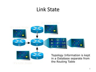
Link State
3
Topology Informationis kept
in a Database separate from
the Routing Table
A
A
B
B
C
C
2
2
13
13
13
13
Q
Q
Z
Z
X
X
Z
Z
X
X
Y
Y
Q
Q
Z’s Link State
Q’s Link State
X’s Link State
4.
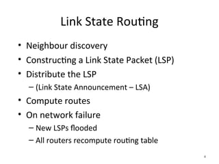
Link State Routing
•Neighbour discovery
• Constructing a Link State Packet (LSP)
• Distribute the LSP
– (Link State Announcement – LSA)
• Compute routes
• On network failure
– New LSPs flooded
– All routers recompute routing table
4
5.
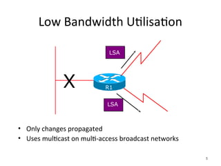
Low Bandwidth Utilisation
•Only changes propagated
• Uses multicast on multi-access broadcast networks
5
LSA
X
LSA
R1
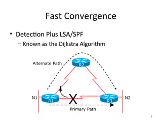
6.
Fast Convergence
• DetectionPlus LSA/SPF
– Known as the Dijkstra Algorithm
6
X N2
Alternate Path
Primary Path
N1
R2
R1 R3
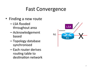
7.
Fast Convergence
• Findinga new route
– LSA flooded
throughout area
– Acknowledgement
based
– Topology database
synchronised
– Each router derives
routing table to
destination network
7
LSA
N1
R1 X
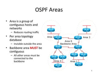
8.
OSPF Areas
• Areais a group of
contiguous hosts and
networks
– Reduces routing traffic
• Per area topology
database
– Invisible outside the area
• Backbone area MUST be
contiguous
– All other areas must be
connected to the
backbone
8
Area 1
Area 2 Area 3
R1 R2
R3
R6
Area 4
R5 R4
R7
R8
Ra
Rd
Rb
Rc
Area 0
Backbone Area
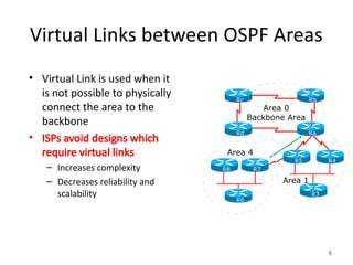
9.
Virtual Links betweenOSPF Areas
• Virtual Link is used when it
is not possible to physically
connect the area to the
backbone
• ISPs avoid designs which
require virtual links
– Increases complexity
– Decreases reliability and
scalability
9
Area 1
R3
R6
Area 4
R5 R4
R7
R8
Ra
Rd
Rb
Rc
Area 0
Backbone Area
10.
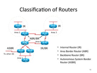
Classification of Routers
•Internal Router (IR)
• Area Border Router (ABR)
• Backbone Router (BR)
• Autonomous System Border
Router (ASBR)
10
R1 R2
R3
R5 R4
Rd Ra
Rb
Rc
IR
ABR/BR
IR/BR
ASBR
To other AS
IR
Area 1
Area 0
Area 2 Area 3
11.
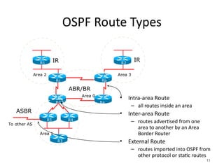
OSPF Route Types
•Intra-area Route
– all routes inside an area
• Inter-area Route
– routes advertised from one
area to another by an Area
Border Router
• External Route
– routes imported into OSPF from
other protocol or static routes
11
R1 R2
R3
R5 R4
Rd Ra
Rb
Rc
IR
ABR/BR
ASBR
To other AS
IR
Area 1
Area 0
Area 2 Area 3
12.
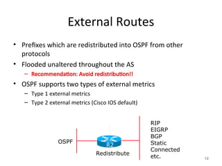
External Routes
• Prefixeswhich are redistributed into OSPF from other
protocols
• Flooded unaltered throughout the AS
– Recommendation: Avoid redistribution!!
• OSPF supports two types of external metrics
– Type 1 external metrics
– Type 2 external metrics (Cisco IOS default)
12
RIP
EIGRP
BGP
Static
Connected
etc.
OSPF
Redistribute
R2
13.
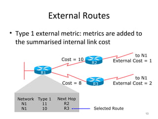
External Routes
• Type1 external metric: metrics are added to
the summarised internal link cost
13
Network
N1
N1
Type 1
11
10
Next Hop
R2
R3
Cost = 10
to N1
External Cost = 1
to N1
External Cost = 2
Cost = 8
Selected Route
R3
R1
R2
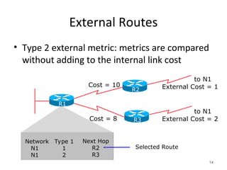
14.
External Routes
• Type2 external metric: metrics are compared
without adding to the internal link cost
14
Cost = 10
to N1
External Cost = 1
to N1
External Cost = 2
Cost = 8
Selected Route
R3
R1
R2
Network
N1
N1
Type 1
1
2
Next Hop
R2
R3
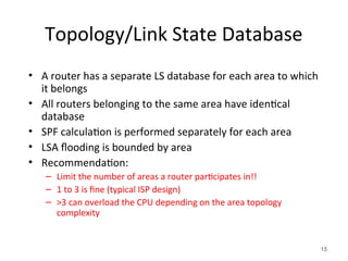
15.
Topology/Link State Database
•A router has a separate LS database for each area to which
it belongs
• All routers belonging to the same area have identical
database
• SPF calculation is performed separately for each area
• LSA flooding is bounded by area
• Recommendation:
– Limit the number of areas a router participates in!!
– 1 to 3 is fine (typical ISP design)
– >3 can overload the CPU depending on the area topology
complexity
15
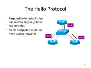
16.
The Hello Protocol
•Responsible for establishing
and maintaining neighbour
relationships
• Elects designated router on
multi-access networks
16
Hello
Hello
Hello
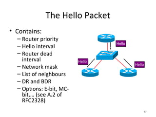
17.
The Hello Packet
•Contains:
– Router priority
– Hello interval
– Router dead
interval
– Network mask
– List of neighbours
– DR and BDR
– Options: E-bit, MC-
bit,… (see A.2 of
RFC2328)
17
Hello
Hello
Hello
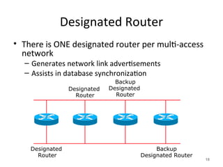
18.
Designated Router
• Thereis ONE designated router per multi-access
network
– Generates network link advertisements
– Assists in database synchronization
18
Designated
Router
Designated
Router
Backup
Designated Router
Backup
Designated
Router
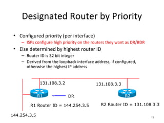
19.
Designated Router byPriority
• Configured priority (per interface)
– ISPs configure high priority on the routers they want as DR/BDR
• Else determined by highest router ID
– Router ID is 32 bit integer
– Derived from the loopback interface address, if configured,
otherwise the highest IP address
19
144.254.3.5
R2 Router ID = 131.108.3.3
131.108.3.2 131.108.3.3
R1 Router ID = 144.254.3.5
DR R2
R1
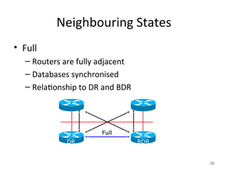
20.
Neighbouring States
• Full
–Routers are fully adjacent
– Databases synchronised
– Relationship to DR and BDR
20
Full
DR BDR
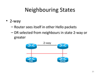
21.
Neighbouring States
• 2-way
–Router sees itself in other Hello packets
– DR selected from neighbours in state 2-way or
greater
21
2-way
DR BDR
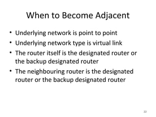
22.
When to BecomeAdjacent
• Underlying network is point to point
• Underlying network type is virtual link
• The router itself is the designated router or
the backup designated router
• The neighbouring router is the designated
router or the backup designated router
22
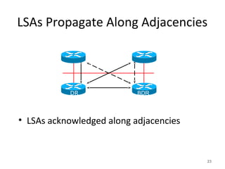
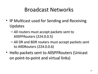
Broadcast Networks
• IPMulticast used for Sending and Receiving
Updates
– All routers must accept packets sent to
AllSPFRouters (224.0.0.5)
– All DR and BDR routers must accept packets sent
to AllDRouters (224.0.0.6)
• Hello packets sent to AllSPFRouters (Unicast
on point-to-point and virtual links)
24
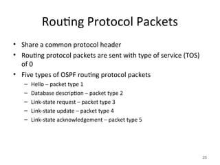
25.
Routing Protocol Packets
•Share a common protocol header
• Routing protocol packets are sent with type of service (TOS)
of 0
• Five types of OSPF routing protocol packets
– Hello – packet type 1
– Database description – packet type 2
– Link-state request – packet type 3
– Link-state update – packet type 4
– Link-state acknowledgement – packet type 5
25
26.
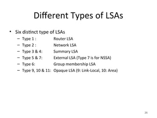
Different Types ofLSAs
• Six distinct type of LSAs
– Type 1 : Router LSA
– Type 2 : Network LSA
– Type 3 & 4: Summary LSA
– Type 5 & 7: External LSA (Type 7 is for NSSA)
– Type 6: Group membership LSA
– Type 9, 10 & 11: Opaque LSA (9: Link-Local, 10: Area)
26
27.
Router LSA (Type1)
• Describes the state and cost of the router’s
links to the area
• All of the router’s links in an area must be
described in a single LSA
• Flooded throughout the particular area and
no more
• Router indicates whether it is an ASBR, ABR,
or end point of virtual link
27
28.
Network LSA (Type2)
• Generated for every transit broadcast and
NBMA network
• Describes all the routers attached to the
network
• Only the designated router originates this LSA
• Flooded throughout the area and no more
28
29.
Summary LSA (Type3 and 4)
• Describes the destination outside the area but
still in the AS
• Flooded throughout a single area
• Originated by an ABR
• Only inter-area routes are advertised into the
backbone
• Type 4 is the information about the ASBR
29
30.
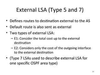
External LSA (Type5 and 7)
• Defines routes to destination external to the AS
• Default route is also sent as external
• Two types of external LSA:
– E1: Consider the total cost up to the external
destination
– E2: Considers only the cost of the outgoing interface
to the external destination
• (Type 7 LSAs used to describe external LSA for
one specific OSPF area type)
30
31.
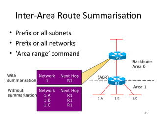
Inter-Area Route Summarisation
•Prefix or all subnets
• Prefix or all networks
• ‘Area range’ command
31
1.A 1.B 1.C
(ABR)
Network
1
Next Hop
R1
Network
1.A
1.B
1.C
Next Hop
R1
R1
R1
With
summarisation
Without
summarisation
Backbone
Area 0
Area 1
R1
R2
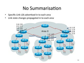
32.
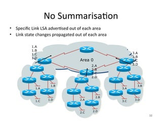
No Summarisation
• SpecificLink LSA advertised out of each area
• Link state changes propagated out of each area
32
3.A
3.B
3.C 3.D
2.A
2.B
2.C 2.D
1.A
1.B
1.C 1.D
1.A
1.B
1.C
1.D
Area 0
2.A
2.B
2.C
2.D
3.A
3.B
3.C
3.D
33.
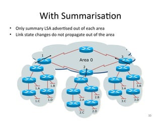
With Summarisation
• Onlysummary LSA advertised out of each area
• Link state changes do not propagate out of the area
33
3.A
3.B
3.C 3.D
2.A
2.B
2.C 2.D
1.A
1.B
1.C 1.D
1
Area 0
2
3
34.
No Summarisation
• SpecificLink LSA advertised in to each area
• Link state changes propagated in to each area
34
3.A
3.B
3.C 3.D
2.A
2.B
2.C 2.D
1.A
1.B
1.C 1.D
2.A 2.B
2.C 2.D
3.A 3.B
3.C 3.D
Area 0
1.A 1.B
1.C 1.D
3.A 3.B
3.C 3.D
1.A 1.B
1.C 1.D
2.A 2.B
2.C 2.D
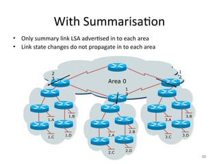
35.
With Summarisation
• Onlysummary link LSA advertised in to each area
• Link state changes do not propagate in to each area
35
3.A
3.B
3.C 3.D
2.A
2.B
2.C 2.D
1.A
1.B
1.C 1.D
2
3
Area 0
1
3
1
2
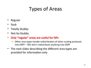
36.
Types of Areas
•Regular
• Stub
• Totally Stubby
• Not-So-Stubby
• Only “regular” areas are useful for ISPs
– Other area types handle redistribution of other routing protocols
into OSPF – ISPs don’t redistribute anything into OSPF
• The next slides describing the different area types are
provided for information only
36
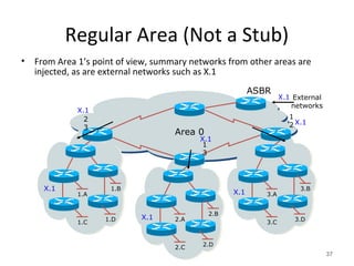
37.
Regular Area (Nota Stub)
• From Area 1’s point of view, summary networks from other areas are
injected, as are external networks such as X.1
37
3.A
3.B
3.C 3.D
2.A
2.B
2.C 2.D
1.A
1.B
1.C 1.D
2
3
Area 0
1
3
1
2
ASBR
External
networks
X.1
X.1
X.1
X.1
X.1
X.1
X.1
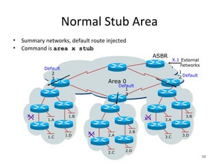
38.
Normal Stub Area
•Summary networks, default route injected
• Command is area x stub
38
3.A
3.B
3.C 3.D
2.A
2.B
2.C 2.D
1.A
1.B
1.C 1.D
2
3
Area 0
1
3
1
2
ASBR
External
networks
X.1
X.1
Default
X.1
X.1
Default
Default
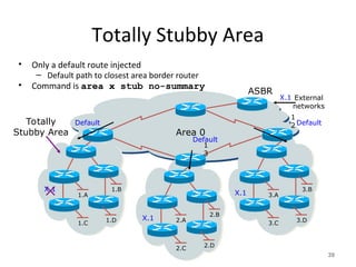
39.
Totally Stubby Area
•Only a default route injected
– Default path to closest area border router
• Command is area x stub no-summary
39
3.A
3.B
3.C 3.D
2.A
2.B
2.C 2.D
1.A
1.B
1.C 1.D
Area 0
1
3
1
2
ASBR
External
networks
X.1
X.1
Default
X.1
X.1
Default
Default
Totally
Stubby Area
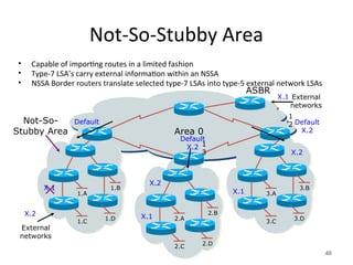
40.
Not-So-Stubby Area
• Capableof importing routes in a limited fashion
• Type-7 LSA’s carry external information within an NSSA
• NSSA Border routers translate selected type-7 LSAs into type-5 external network LSAs
40
3.A
3.B
3.C 3.D
2.A
2.B
2.C 2.D
1.A
1.B
1.C 1.D
Area 0
1
3
1
2
ASBR
External
networks
X.1
X.1
Default
X.1
X.1
Default
X.2
Default
X.2
Not-So-
Stubby Area
External
networks
X.2
X.2
X.2
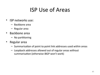
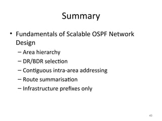
41.
ISP Use ofAreas
• ISP networks use:
– Backbone area
– Regular area
• Backbone area
– No partitioning
• Regular area
– Summarisation of point to point link addresses used within areas
– Loopback addresses allowed out of regular areas without
summarisation (otherwise iBGP won’t work)
41
42.
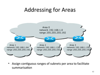
Addressing for Areas
•Assign contiguous ranges of subnets per area to facilitate
summarisation
42
Area 1
network 192.168.1.64
range 255.255.255.192
Area 2
network 192.168.1.128
range 255.255.255.192
Area 3
network 192.168.1.192
range 255.255.255.192
Area 0
network 192.168.1.0
range 255.255.255.192
Acknowledgement and Attribution
Thispresentation contains content and information
originally developed and maintained by the following
organisation(s)/individual(s) and provided for the
African Union AXIS Project
Philip Smith: - pfsinoz@gmail.com
Cisco ISP/IXP Workshops
www.apnic.net