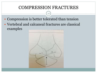
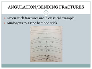
CHAIRPERSON: DR.RUPA KUMAR CS
MODERATOR: DR. SHESHAGIRI V
BIOMATERIALS AND
APPLIED BIOMECHANICS
1
CONTENTS
 BASIC CONCEPTS
 BIOMATERIALS
 BIOMECHANICS OF FRACTURES
 BIOMECHANICS OF FRACTURE HEALING
2
 BIOMECHANICS OF INTRAMEDULLARY NAILS
 BIOMECHANICS OF BONE SCREWS
 BIOMECHANICS OF BONE PLATES
3
BASIC CONCEPTS
 STRESS
Intensity of internal force
Stress = Force/Area (pascals)
Depends on mode of application of force
TWO TYPES: Normal (compressive and tensile) and
Shearing(bending and torsional)
4
 STRAIN
 Relative measure of deformation resulting from
loading
 Strain = Change in length/original length
 Can also be normal or shearing
5
CONCEPT OF COLUMN BENDING
 Occurs only when a beam is loaded eccentrically
 Generates compressive forces on the concave side
and tensile forces or the convex side
 Analogous to most weight bearing bones
6
CANTILEVER BENDING
 Horizontally disposed beam with one end fixed to a
wall when loaded at its free end leads to bending of
the beam
7
 ELASTICITY
Behavior of elongation when loaded and recovery to
its original state when unloaded
 PLASTICITY
Permanent deformation of material under load
 Hooke’ s law
Deformation is proportional to the applied load upto
a limiting value
8
Young’s modulus of elasticity (E)
 a measure of the material’s ability to resist
deformation in tension
 E = stress/strain
 E is the slope in the elastic range of the stress-strain
curve
9
10
BIOMATERIALS
Brittle materials (e.g., PMMA)
 Stress-strain curve is linear up to failure.
 These materials undergo only recoverable (elastic)
deformation before failure.
 They have little or no capacity for plastic
deformation
11
Ductile materials (e.g., metal)
 These materials undergo large plastic deformation
before failure.
 Ductility is a measure of post yield deformation.
Viscoelastic materials (e.g., bone and ligaments)
 Stress-strain behavior is time-rate dependent.
 Properties depend on load magnitude and rate at
which the load is applied.
 A function of internal friction
 These materials exhibit both fluid (viscosity) and solid
(elasticity) properties.
12
 These materials exhibit both fluid (viscosity) and
solid (elasticity) properties.
 Modulus increases as strain rate increases.
 These materials exhibit hysteresis.
 Loading and unloading curves differ.
 Energy is dissipated during loading.
13
INERTIA
 Force of resistance tending to prevent any change in the
existing state of its motion.
 Proportional to the mass of the body
 MOMENT OF INERTIA : resistance of a body at rest
capable of rotatory motion
 3 types
MASS MOMENT OF INERTIA
AREA MOMENT OF INERTIA
POLAR MOMENT OF INERTIA
14
MASS MOMENT OF INERTIA
 Depends on the distribution of material around the
axis of rotation rather than the total mass of the body
 I=mr2
 m = mass of the body, r = radius of gyration
(perpendicular distance to center of the mass)
15
AREA AND POLAR MOMENT OF INERTIA
 AREA MOMENT OF INERTIA:Resistance offered by a
structure when placed under a bending load
 Depends on the shape of its cross section
 Formulae differ depending on the different geometric
cross sections used
 POLAR MOMENT OF INERTIA: rigidity or strength of a
rod or tube against torsional stress.
16
ORTHOPEDIC IMPLANTS
 METALS
Steel based, cobalt based, titanium based
 NON METALS
Polyethylene, PMMA, Silicones, Ceramics
17
STAINLESS STEEL (316 L)
 Iron-carbon, chromium, nickel, molybdenum,
manganese
 Nickel: increases corrosion resistance and stabilizes
molecular structure
 Chromium: forms a passive surface oxide,
improving corrosion resistance
 Molybdenum: prevents pitting and crevice
corrosion
 Manganese: improves crystalline stability
 “L” = low carbon: greater corrosion resistance
18
COBALT BASED
 Cobalt-chromium-molybdenum (Co-Cr-Mo)
 65% cobalt, 35% chromium, 5% molybdenum
 Special forging process
 Nickel may be added to improve ease of forging
 Co-Cr: macrophage proliferation and synovial
degeneration
 Ions excreted through the kidneys
19
TITANIUM BASED
 Titanium is extremely biocompatible:
 Rapidly forms an adherent oxide coating
(selfpassivation); decreases corrosion
 A nonreactive ceramic coating
 Relatively low E
 Most closely emulates axial and torsional
stiffness of bone
 High yield strength
20
PROBLEMS WITH METALS
 Fatigue failure
Occurs with cyclic loading at stress below ultimate
tensile strength
Depends on magnitude of stress and number of cycles
Endurance limit: Maximum stress under which the
material will not fail regardless of number of loading
cycles
If the stress is below this limit, the material may be
loaded cyclically an infinite number of times (more
than 106 cycles) without breaking.
Above this limit, fatigue life is expressed by the S-n
curve: Stress (S) versus the number of cycles (n)
21
 Creep (cold flow)
Progressive deformation response to constant force
over an extended period of time
Sudden stress followed by constant loading causes
continued deformation
Can produce permanent deformity
May affect mechanical function (e.g., in TJA)
22
23
 Corrosion can be decreased in the following ways:
1.Using similar metals
2.Proper implant design
3.Passivation by an adherent oxide layer effectively
separates metal from solution
For example, stainless steel coated with chromium
oxide
24
NON METALS
 POLYETHYLENE
Ultra–high-molecular-weight polyethylene (UHMWPE)
Polymer of long carbon chains
Used in weight-bearing components of TJA Acetabular
cups, tibial trays
Wear characteristics superior to those of high-density
polyethylene
Tough, ductile, resilient, resistant to wear, low
friction
25
 DISADVANTAGES
Major disadvantage is : WEAR DAMAGE
Can be decreased by:
1.GAMMA IRRADIATION
increases polymer chain cross-links.
Greatly improves wear characteristics
However, reduces resistance to fatigue and fracture
Decreases elastic modulus, tensile strength,
ductility, and yield stress
26
 Annealing
Heating to below melting point
Decreases free radicals
Good mechanical properties; does not disrupt
crystalline areas
27
PMMA(POLYMETHYL METHACRYLATE)
 Used for fixation and load distribution for implants
 Act as a grout, not an adhesive
 Mechanically interlocks with bone
 Reaches ultimate strength within 24 hours
 Can be used as an internal splint for patients with
poor bone stock
 PMMA can be used as a temporary internal splint
until the bone heals.
 If the bone fails to heal, the PMMA will ultimately
fail.
28
 Poor tensile and shear strength
 Is strongest in compression and has a low E
 Not as strong as bone in compression
 Reducing voids (porosity) increases cement strength
and decreases cracking.
 Vacuum mixing, centrifugation, good technique
 Cement failure often caused by microfracture and
fragmentation
 Insertion can lead to a precipitous drop in blood
pressure.
29
 SILICONES
Polymers for replacement in non–weight-bearing
Joints.
Poor strength and wear capabilities.
Frequent synovitis with extended use.
 CERAMICS
Metallic and non metallic elements bonded ionically in a highly
oxidized state
Good insulators (poor conductors)
1. Biostable (inert) crystalline materials such as Al2O3
(alumina) and ZrO2 (zirconium dioxide)
2. Bioactive (degradable), noncrystalline substances
such as bioglass
30
 Typically brittle (no plastic deformation)
 High modulus (E)
 High compressive strength
 Low tensile strength
 Low yield strain
 Poor crack resistance characteristics
 Low resistance to fracture
 Best wear characteristics, with polyethylene and a
low oxidation rate
31
 High surface wettability and high surface tension
 Highly conducive to tissue bonding
 Less friction and diminished wear (“smooth
surface”)
 Small grain size allows an ultrasmooth finish
Less friction
 Calcium phosphates (e.g., hydroxyapatite) may be
useful as a coating (plasma sprayed) to increase
attachment strength and promote bone healing.
32
33
34
BIOMECHANICS OF FRACTURES
 PERKINS classification (1958)
 (A)DIRECT TRAUMA
Tapping fractures
Crush Fractures
Penetrating or Gunshot fractures
 (B) INDIRECT TRAUMA
Compression fractures
Tension Fractures
Angular/bending fracture
Torsional/rotational/spiral fracture
35
TAPPING FRACTURES
 Linear, complete, transverse fracture caused by a
small force of “dying momentum” acting over a small
area. Surrounding tissue often normal.
36
CRUSHING FRACTURES
 Direct application of large force over large area.
Usually commmunited
37
PENETRATING FRACTURES
 Due to large force over a small area.
 Usually due to gunshot injuries
38
TENSION FRACTURES
 Occur in Cancellous or corcticocancellous bones and
are usually transverse
 Fracture of patella is classical example
39
COMPRESSION FRACTURES
 Compression is better tolerated than tension
 Vertebral and calcaneal fractures are classical
examples
40
ANGULATION/BENDING FRACTURES
 Green stick fractures are a classical example
 Analogous to a ripe bamboo stick
41
TORSIONAL/SPIRAL FRACTURES
 Fracture surface is circular/ oval with vertical
spicules at both ends
 Combination of compressive and tensile forces
 Torsion is directly proportional to the Radius
 Torsion is inversely proportional to the polar
moment of inertia
 Explains why rotational fractures are more common
in lower one third of tibia than upper one third
42
43
FRACTURE HEALING
 FRACTURE HEALING:
PHASE I: CALLUS FORMATION
CELLULAR RESPONSE
VASCULAR RESPONSE
PHASE II: REMODELLING
44
CELLULAR RESPONSE
45
VASCULAR RESPONSE
46
BIOMECHANICS OF FRACTURE HEALING
 PRIMARY HEALING
Without callus formation
Seen in rigid internally fixed fractures
CONTACT HEALING
GAP HEALING
 SECONDARY FRACTURE HEALING
With callus formation
47
HEALING UNDER BONE PLATING
 Based on the relation between the magnitude of gap
between fracture fragments remaining after fixation
and maximum movement permitted by the stability
achieved after fixation.
 Depends on strain at the fracture site (change in
length/original length). Different tissues tolerate
different strain values.
 Perren et al described it.
48
 If interfragmentary gap = 3mm , interfragmentary movement = 3mm, Strain =
100%, promotes Collagen formation
 If interfragmentary gap = 6mm, interfragmentary movement = 3mm , Strain = 50%
 If interfragmentary gap = 6mm, interfragmentary movement = 1mm , Strain = 10%,
promotes collagen formation
 In a similar fashion, if strain levels of <2% are achieved it promotes osteoblast
formation directly
49
50
BIOMECHANICS OF INTRAMEDUALLRY NAILS
 IM nails can be broadly categorised as
1.Sliding or gliding nails
Eg: - K (kuntscher) nails, schneider nails, hansen
street nails, sampsons fluted nails, rush nail.
2.Interlocking nails
Screws bind the nail. Prevent any kind of motion.
51
STRUCTURAL ANALYSIS OF NAILS
 EFFICIENY OF A NAIL DEPENDS ON
1 . The material used for its construction (imparts
strength)
2.The design geometry (imparts rigidity/stiffness)
Choice is guided by above two considerations
52
SOLID OR A HOLLOW NAIL?
 Area moment of a solid nail = 3.14 x r4 / 4
 If dia = 10mm, r = 5mm , Area moment = 490.6
 If nail is hollow with 10 mm dia and 2mm thickness
Area moment = 3.14(r1 – r2)/4 = 427 (slightly
stronger)
 If a 2mm thickness hollow nail is made using the same
material used to make the solid nail, diameter will be
16mm
 Area moment now will be 2198
 Rigidity is thus 4.5 times greater than that of solid nail
53
 Polar moment of inertia(solid nail) = 3.14 x r4 / 2 =
981.25
 Hollow nail constructed the same way = 3.14 x 84
=6430.72 (6.6 times greater)
 Therefore, a hollow nail is much stronger than a solid
nail i.e. further the material is spread away from the
neutral axis, greater is its resistance to bending and
torsional forces
 Similar calculations can be done for nails with different
cross sections showing similar results
54
CLOSED OR OPEN SECTION?
 Closed section: Russell Taylor nail
 Open section : k nail
 Area moment is almost similar for both nails as
circumference is almost same
 Polar moment significantly changes due to
discontinuity which leads to interruption in
transmission of stress forces leading to reduced
resistance to torsional forces
 This effect can be avoided to some extent by making
the cross section clover leaf shaped
55
56
STRENGTH OF NAIL BONE CONSTRUCT
 Depends on working length and gripping strength.
 Working length is that part of the nail which is not
covered by the bone after completion of the surgery.
 Part which underlies residual fracture gap
 Stiffness of the nail against bending force is inversely
proportional to the square of working length
 Rigidity of nail against torsional forces is also inversely
related to working length
 Shorter the working length, greater is the bending and
torsional rigidity of the nail bone construct.
57
GRIPPING STRENGTH
 magnitude of force by which slipping of nail axially
at the bone nail interface at the time of transmission
of forces between the fracture fragments is
prevented.
 Bone tissue exerts an equal and opposite force on the
nail which is designated as hoop stress
 Slotted hollow nails have a distinct advantage in this
regard
 Compression during entry exerts elastic force on the
canal wall which mantains acceptable magnitude of
gripping strength in the post operative period.
58
59
DISADVANTAGES OF INTERLOCKING NAILS
 1. Residual inter fragmentary gap is always there
since the nail is locked. Increases due to necrosis at
the bone metal interface. Fall in hoop stress.
 Not seen in gliding nails. Fragments glide along
surface of nail , reduction in fracture gap leading to
healing.
 Can be avoided in interlocking nails with the help of
dynamisation
60
 2. Working length of the locked nail spans between
the locking screws leading to less resistance to
bending and torsional forces
 This can only be averted by using nails of increased
thickness which can be achieved by keeping the
inner diameter constant
 Proximal part of the nail should be hollow and round
and close sectioned because the subtrochanteric
region is the area of maximum stress and such
design helps in increased resistance against bending
and torsional forces
61
 3. Holes or gaps within the nail act as stress raisers.
 Since lower limbs undergo cantilever bending the
stress is maximum at the distal end of the nail
 The lower the fracture is, lesser is the supporting
effect of the bone
 Therefore fractures of the distal end of the femur are
not amenable to fixation by nails introduced
proximally.
 Nails introduced from the intercondylar notch of
femur with the locking sequence reversed are used
62
BIOMECHANICS OF BONE SCREWS
63
64
CORE
 It is the solid shaft on which the thread is spiralled
 There is a core diameter/root diameter and a major/
outer diameter
 The cross sectional diemeter of the root or the core
determines the tensile and torsional strength of the
screw
65
66
SCREW THREADS
 Most important constituent of the screw.
 May be visualized as a narrow width inclined plane spiralled
around the core like a helix to conserve space
 Based on the mechanics of an inclined plane.
 Any load can be lifted to the same height with the use of a
lesser force than needed to lift it vertically up, when it is
pulled along a sloping ramp
 Similarly, driving a peg in to a block of wood requires more
force than to drive a screw
67
68
W =weight of object = 100 kg
W2 = normal component of w = wcosθ
W1 = shearing component of w = wsinθ which tends to
pull the object towards O.
F = pulling force
If θ = 20 degrees, w1 = 100sin 20 = 0.34 x 100 = 34kg
Therefore, magnitude of pulling force is much lesser
than 100 kg.
Same priniciple helps screws function more efficiently
69
ANGLE OF REPOSE
 Upto a point on the inclination of the inclined plane, no
sliding will actually take place
 Until an angle is reached following which the tendency of
the object to slide down progressively increases leading
to increased work against the pulling force and decreased
efficiency. Known as angle of repose.
 This angle is the factor guiding the magnitude of
inclination of the plane to make it a most efficient simple
machine. Inclination of screw threads is so adjusted that
maximum mechanical advantage is matched with the
maximum number of threads accommodated in unit
length of screw
70
SCREW TIPS
 Blunt rounded off tips without flutes
 Blunt rounded off tips with flutes
 Trocar point tips
 Cork screw tips
71
72
MECHANICS OF DRIVNG A SCREW
 Torque is directly transmitted to the core and the threads
of the screw. Ultimate movement is translatory
 Example of coupling of motion
 If applied force = 2N
 Head dia = 18mm, outer dia = 4.5mm, core dia=3mm
 Torque at head = force x dia = 36N-m
 Force at the thread = torque / dia = 16 N
 Force at Core = 24 N
 Therefore the force is magnified 8 times and 12 times
respectively
73
PITCH AND LEAD
74
TYPES OF SCREWS
1. CORTICAL SCREWS
 may either be self tapping or non self tapping
 Self tapping may have a prismatic trocar tip with
three sharp edges or rounded tip with flutes covering
the last 3 threads
 Non self tapping have blunt rounded tips and cannot
be inserted without pretapping with a special
instrument.
 However they offer better precision and lesser force.
75
CANCELLOUS SCREWS
 Narrower core diameter, wider threads, no tapering
towards the tip
 May be fully or partly threaded. Unthreaded part is
called shank. Core diameter always lesser than the
shank
 Tapping usually not required unless it is the
epiphyseal ends of long bones where the bone is
corticocancellous or in younger subjects having
tougher metaphyseal bones
76
77
SLIDING COMPRESSION SCREWS
 Specially designed partly threaded large cancellous
screws
 Cannulated and headless
 The headless shaft of the screw can be telescoped into the
barrel of the angled blade plate.
 The barrel of the plate is so designed that the head of the
locking nut cannot pass through the barrel and as the nut
is tightened it forces the unthreaded shaft of the screw to
slide backwards
 The threadless shaft of the screw slides along the barrel
with each turn of the nut and at one point starts
compressing the fracture surfaces. This is why it is called
a sliding hip screw.
78
LAG EFFECT
 The word lag means unable to keep pace with fellows and to
fall behind during movement.
 In mechanics, it means lack of movement of one of the two
fracture fragments under the process of fixation by a screw
 Can be achieved in two ways
1. Using a oversized hole in the proximal fragment so that
screw threads do not take purchase in proximal fragment
2. Using a partly threaded screw
ONLY THE FRAGMENT THROUGH WHICH THE SCREW
THREADS ARE MOVING WILL MOVE IN THE DIRECTION
OPPOSITE TO THAT OF THE SCREW ALONG ITS AXIS.
LAG EFFECT IS A TOOL TO APPLY INTERFRAGMENTARY
COMPRESSION
79
80
BIOMECHANICS OF BONE PLATES
 Design: Semitubular plate, one third tubular plate
 Material: SS plates, titanium plates
 Shape of hole: round slots, oval slots
 Shape: Angled blade plates, clover leaf plates, cobra
head plates
 Biological factors: limited contact plates,
semitubular plates
 Functional classification: Neutralization plates,
compression plates, Butress plates
81
NEUTRALIZATION PLATES
 Act as bridge between fragments
 Every bone plate is a neutralization plate
 Eg: sherman and lane plates were neutralization
plates
 Offer poor resistance against bending, shearing and
torsional loading
 Needs to be supplemented with compression
(introduced by danis in 1949) either by altering its
design or applying screws
82
COMPRESSION PLATES
 May be applied with the screw or with the plate itself
 May be used in two different modes
1. Inter fragmentary compression
Between the fracture fragments, can be applied only
with screw itself
2.Axial compression
Line of force passes through the plate itself as bone plate is
a splint which is applied to the surface of the bone.
So the line of action of compressive force applied through a
bone plate not in line with the neutral axis i.e. it is a
contra axial application mode.
83
84
METHODS OF OVERCOMING EFFECT OF
ECCENTRIC LOADING
 1. To apply the plate on the TENSION side of the
bone. However, since the bone is an anisotropic
material, the compression or tension on the bones
changes according to instantaneous loading pattern
and is difficult to identifu
 2. PREBENDING of plates: Bending effect caused by
eccentric loading imposed by the compression plate
will be balanced by the counter bending effect of
prebending leading to uniform compression
85
86
INTERFRAGMENTARY COMPRESSION
 SISK (1989) recommended insertion of screw at right
angles to long axis of bone for fixing long oblique
fractures and spiral fractures without communition.
 P = force acting perpendicular to bone
 F-f = fracture line
 R = force pulling the far fragment towards near fragment
impressed on F-f at an angle <90
 Hence force will resolve into normal and shearing.
 Shearing component will cause sliding of fracture
surfaces with consequent loss of alignment
87
88
 Compression screw placed perpendicular to the
fracture surface does not generate any shearing
force, but stability under axial loading is less which
allows interfragmentary sliding
 To overcome this difficulty, Muller et al in 1990
recommended placement of one central screw at
right angles to the long axis of bone and one screw at
right angles to the fracture plane
89
90
COMPRESSION IN LONG OBLIQUE
FRACTURES WITH BUTTERFLY FRAGMENT
 Use of multiples screws is recommended
 Multiple screws also do not offer enough stability and
need to be supplemented with neutralization plates
 Primary lag screw fixation to stabilize fragments followed
by supplementation with neutralization plate without
compression is the rule.
 If the plane of the fracture changes from place to place,
(spiral) placement of lag screws should be such that each
screw is perpendicular to the fracture surface underlying
that area.
 In fractures with butterfly fragment, two screws must be
placed following the principle of “bisecting angle”
91
92
APPLICATION OF COMPRESSION
 PRINCIPLE: tensioning the plate and fixing it on the
bone across the fracture line
May be achieved using
1. MULLERS apparatus
2. PLATES WITH OVAL SLOTS (semitubular and one
third tubular plates.
3. DYNAMIC COMPRESSION PLATING
93
MULLERS APPARATUS
 Plate is fixed to the smaller fragment.
 Hook of the tension apparatus with the jaws fully
open is engaged to the notch in the last hole of the
plate overlying the unfixed fragment.
 The small plate with a single hole hinged to mullers
apparatus is now fixed to the larger unfixed fragment
with screw.
 Gadget applies tensile force to the plate which in
turn applies compression to the bone
 It is an excellent method with the drawback of a
wider exposure
94
95
PLATES WITH OVAL SLOTS
 Maximum transverse diameter of the elliptical or oval slot of
the plate is a little less than the maximum head diameter and
lesser towards the ends,
 Only if the plate moves in the direction of the arrow to bring
major axis of the elliptical hole to match the maximum
diameter of the screw head, the head can enter into the slot
 Once the screw is introduced the plate along with the
fragment anchored to it, undergoes linear acceleration to its
counterpart.
 Strength and rigidity of these plates is not high, since only the
margins and not entire surface is contact with bone surface.
Compression of periosteum is mimimal
 These plates are biologically superior but mechanically
inferior
96
97
DYNAMIC COMPRESSION PLATES
 Also self compressing plates but the geometry of
plate holes makes it more versatile
 Much thicker and stronger
 One or both margins of the oval hole are slanting
inwards to make it an inclined plane.
 Downward movement of the screw thus gets an
adjunct forward movement imparting axial
compression .
98
99
100
101

orthopedic implants

  • 1.
    CHAIRPERSON: DR.RUPA KUMARCS MODERATOR: DR. SHESHAGIRI V BIOMATERIALS AND APPLIED BIOMECHANICS 1
  • 2.
    CONTENTS  BASIC CONCEPTS BIOMATERIALS  BIOMECHANICS OF FRACTURES  BIOMECHANICS OF FRACTURE HEALING 2
  • 3.
     BIOMECHANICS OFINTRAMEDULLARY NAILS  BIOMECHANICS OF BONE SCREWS  BIOMECHANICS OF BONE PLATES 3
  • 4.
    BASIC CONCEPTS  STRESS Intensityof internal force Stress = Force/Area (pascals) Depends on mode of application of force TWO TYPES: Normal (compressive and tensile) and Shearing(bending and torsional) 4
  • 5.
     STRAIN  Relativemeasure of deformation resulting from loading  Strain = Change in length/original length  Can also be normal or shearing 5
  • 6.
    CONCEPT OF COLUMNBENDING  Occurs only when a beam is loaded eccentrically  Generates compressive forces on the concave side and tensile forces or the convex side  Analogous to most weight bearing bones 6
  • 7.
    CANTILEVER BENDING  Horizontallydisposed beam with one end fixed to a wall when loaded at its free end leads to bending of the beam 7
  • 8.
     ELASTICITY Behavior ofelongation when loaded and recovery to its original state when unloaded  PLASTICITY Permanent deformation of material under load  Hooke’ s law Deformation is proportional to the applied load upto a limiting value 8
  • 9.
    Young’s modulus ofelasticity (E)  a measure of the material’s ability to resist deformation in tension  E = stress/strain  E is the slope in the elastic range of the stress-strain curve 9
  • 10.
  • 11.
    BIOMATERIALS Brittle materials (e.g.,PMMA)  Stress-strain curve is linear up to failure.  These materials undergo only recoverable (elastic) deformation before failure.  They have little or no capacity for plastic deformation 11
  • 12.
    Ductile materials (e.g.,metal)  These materials undergo large plastic deformation before failure.  Ductility is a measure of post yield deformation. Viscoelastic materials (e.g., bone and ligaments)  Stress-strain behavior is time-rate dependent.  Properties depend on load magnitude and rate at which the load is applied.  A function of internal friction  These materials exhibit both fluid (viscosity) and solid (elasticity) properties. 12
  • 13.
     These materialsexhibit both fluid (viscosity) and solid (elasticity) properties.  Modulus increases as strain rate increases.  These materials exhibit hysteresis.  Loading and unloading curves differ.  Energy is dissipated during loading. 13
  • 14.
    INERTIA  Force ofresistance tending to prevent any change in the existing state of its motion.  Proportional to the mass of the body  MOMENT OF INERTIA : resistance of a body at rest capable of rotatory motion  3 types MASS MOMENT OF INERTIA AREA MOMENT OF INERTIA POLAR MOMENT OF INERTIA 14
  • 15.
    MASS MOMENT OFINERTIA  Depends on the distribution of material around the axis of rotation rather than the total mass of the body  I=mr2  m = mass of the body, r = radius of gyration (perpendicular distance to center of the mass) 15
  • 16.
    AREA AND POLARMOMENT OF INERTIA  AREA MOMENT OF INERTIA:Resistance offered by a structure when placed under a bending load  Depends on the shape of its cross section  Formulae differ depending on the different geometric cross sections used  POLAR MOMENT OF INERTIA: rigidity or strength of a rod or tube against torsional stress. 16
  • 17.
    ORTHOPEDIC IMPLANTS  METALS Steelbased, cobalt based, titanium based  NON METALS Polyethylene, PMMA, Silicones, Ceramics 17
  • 18.
    STAINLESS STEEL (316L)  Iron-carbon, chromium, nickel, molybdenum, manganese  Nickel: increases corrosion resistance and stabilizes molecular structure  Chromium: forms a passive surface oxide, improving corrosion resistance  Molybdenum: prevents pitting and crevice corrosion  Manganese: improves crystalline stability  “L” = low carbon: greater corrosion resistance 18
  • 19.
    COBALT BASED  Cobalt-chromium-molybdenum(Co-Cr-Mo)  65% cobalt, 35% chromium, 5% molybdenum  Special forging process  Nickel may be added to improve ease of forging  Co-Cr: macrophage proliferation and synovial degeneration  Ions excreted through the kidneys 19
  • 20.
    TITANIUM BASED  Titaniumis extremely biocompatible:  Rapidly forms an adherent oxide coating (selfpassivation); decreases corrosion  A nonreactive ceramic coating  Relatively low E  Most closely emulates axial and torsional stiffness of bone  High yield strength 20
  • 21.
    PROBLEMS WITH METALS Fatigue failure Occurs with cyclic loading at stress below ultimate tensile strength Depends on magnitude of stress and number of cycles Endurance limit: Maximum stress under which the material will not fail regardless of number of loading cycles If the stress is below this limit, the material may be loaded cyclically an infinite number of times (more than 106 cycles) without breaking. Above this limit, fatigue life is expressed by the S-n curve: Stress (S) versus the number of cycles (n) 21
  • 22.
     Creep (coldflow) Progressive deformation response to constant force over an extended period of time Sudden stress followed by constant loading causes continued deformation Can produce permanent deformity May affect mechanical function (e.g., in TJA) 22
  • 23.
  • 24.
     Corrosion canbe decreased in the following ways: 1.Using similar metals 2.Proper implant design 3.Passivation by an adherent oxide layer effectively separates metal from solution For example, stainless steel coated with chromium oxide 24
  • 25.
    NON METALS  POLYETHYLENE Ultra–high-molecular-weightpolyethylene (UHMWPE) Polymer of long carbon chains Used in weight-bearing components of TJA Acetabular cups, tibial trays Wear characteristics superior to those of high-density polyethylene Tough, ductile, resilient, resistant to wear, low friction 25
  • 26.
     DISADVANTAGES Major disadvantageis : WEAR DAMAGE Can be decreased by: 1.GAMMA IRRADIATION increases polymer chain cross-links. Greatly improves wear characteristics However, reduces resistance to fatigue and fracture Decreases elastic modulus, tensile strength, ductility, and yield stress 26
  • 27.
     Annealing Heating tobelow melting point Decreases free radicals Good mechanical properties; does not disrupt crystalline areas 27
  • 28.
    PMMA(POLYMETHYL METHACRYLATE)  Usedfor fixation and load distribution for implants  Act as a grout, not an adhesive  Mechanically interlocks with bone  Reaches ultimate strength within 24 hours  Can be used as an internal splint for patients with poor bone stock  PMMA can be used as a temporary internal splint until the bone heals.  If the bone fails to heal, the PMMA will ultimately fail. 28
  • 29.
     Poor tensileand shear strength  Is strongest in compression and has a low E  Not as strong as bone in compression  Reducing voids (porosity) increases cement strength and decreases cracking.  Vacuum mixing, centrifugation, good technique  Cement failure often caused by microfracture and fragmentation  Insertion can lead to a precipitous drop in blood pressure. 29
  • 30.
     SILICONES Polymers forreplacement in non–weight-bearing Joints. Poor strength and wear capabilities. Frequent synovitis with extended use.  CERAMICS Metallic and non metallic elements bonded ionically in a highly oxidized state Good insulators (poor conductors) 1. Biostable (inert) crystalline materials such as Al2O3 (alumina) and ZrO2 (zirconium dioxide) 2. Bioactive (degradable), noncrystalline substances such as bioglass 30
  • 31.
     Typically brittle(no plastic deformation)  High modulus (E)  High compressive strength  Low tensile strength  Low yield strain  Poor crack resistance characteristics  Low resistance to fracture  Best wear characteristics, with polyethylene and a low oxidation rate 31
  • 32.
     High surfacewettability and high surface tension  Highly conducive to tissue bonding  Less friction and diminished wear (“smooth surface”)  Small grain size allows an ultrasmooth finish Less friction  Calcium phosphates (e.g., hydroxyapatite) may be useful as a coating (plasma sprayed) to increase attachment strength and promote bone healing. 32
  • 33.
  • 34.
  • 35.
    BIOMECHANICS OF FRACTURES PERKINS classification (1958)  (A)DIRECT TRAUMA Tapping fractures Crush Fractures Penetrating or Gunshot fractures  (B) INDIRECT TRAUMA Compression fractures Tension Fractures Angular/bending fracture Torsional/rotational/spiral fracture 35
  • 36.
    TAPPING FRACTURES  Linear,complete, transverse fracture caused by a small force of “dying momentum” acting over a small area. Surrounding tissue often normal. 36
  • 37.
    CRUSHING FRACTURES  Directapplication of large force over large area. Usually commmunited 37
  • 38.
    PENETRATING FRACTURES  Dueto large force over a small area.  Usually due to gunshot injuries 38
  • 39.
    TENSION FRACTURES  Occurin Cancellous or corcticocancellous bones and are usually transverse  Fracture of patella is classical example 39
  • 40.
    COMPRESSION FRACTURES  Compressionis better tolerated than tension  Vertebral and calcaneal fractures are classical examples 40
  • 41.
    ANGULATION/BENDING FRACTURES  Greenstick fractures are a classical example  Analogous to a ripe bamboo stick 41
  • 42.
    TORSIONAL/SPIRAL FRACTURES  Fracturesurface is circular/ oval with vertical spicules at both ends  Combination of compressive and tensile forces  Torsion is directly proportional to the Radius  Torsion is inversely proportional to the polar moment of inertia  Explains why rotational fractures are more common in lower one third of tibia than upper one third 42
  • 43.
  • 44.
    FRACTURE HEALING  FRACTUREHEALING: PHASE I: CALLUS FORMATION CELLULAR RESPONSE VASCULAR RESPONSE PHASE II: REMODELLING 44
  • 45.
  • 46.
  • 47.
    BIOMECHANICS OF FRACTUREHEALING  PRIMARY HEALING Without callus formation Seen in rigid internally fixed fractures CONTACT HEALING GAP HEALING  SECONDARY FRACTURE HEALING With callus formation 47
  • 48.
    HEALING UNDER BONEPLATING  Based on the relation between the magnitude of gap between fracture fragments remaining after fixation and maximum movement permitted by the stability achieved after fixation.  Depends on strain at the fracture site (change in length/original length). Different tissues tolerate different strain values.  Perren et al described it. 48
  • 49.
     If interfragmentarygap = 3mm , interfragmentary movement = 3mm, Strain = 100%, promotes Collagen formation  If interfragmentary gap = 6mm, interfragmentary movement = 3mm , Strain = 50%  If interfragmentary gap = 6mm, interfragmentary movement = 1mm , Strain = 10%, promotes collagen formation  In a similar fashion, if strain levels of <2% are achieved it promotes osteoblast formation directly 49
  • 50.
  • 51.
    BIOMECHANICS OF INTRAMEDUALLRYNAILS  IM nails can be broadly categorised as 1.Sliding or gliding nails Eg: - K (kuntscher) nails, schneider nails, hansen street nails, sampsons fluted nails, rush nail. 2.Interlocking nails Screws bind the nail. Prevent any kind of motion. 51
  • 52.
    STRUCTURAL ANALYSIS OFNAILS  EFFICIENY OF A NAIL DEPENDS ON 1 . The material used for its construction (imparts strength) 2.The design geometry (imparts rigidity/stiffness) Choice is guided by above two considerations 52
  • 53.
    SOLID OR AHOLLOW NAIL?  Area moment of a solid nail = 3.14 x r4 / 4  If dia = 10mm, r = 5mm , Area moment = 490.6  If nail is hollow with 10 mm dia and 2mm thickness Area moment = 3.14(r1 – r2)/4 = 427 (slightly stronger)  If a 2mm thickness hollow nail is made using the same material used to make the solid nail, diameter will be 16mm  Area moment now will be 2198  Rigidity is thus 4.5 times greater than that of solid nail 53
  • 54.
     Polar momentof inertia(solid nail) = 3.14 x r4 / 2 = 981.25  Hollow nail constructed the same way = 3.14 x 84 =6430.72 (6.6 times greater)  Therefore, a hollow nail is much stronger than a solid nail i.e. further the material is spread away from the neutral axis, greater is its resistance to bending and torsional forces  Similar calculations can be done for nails with different cross sections showing similar results 54
  • 55.
    CLOSED OR OPENSECTION?  Closed section: Russell Taylor nail  Open section : k nail  Area moment is almost similar for both nails as circumference is almost same  Polar moment significantly changes due to discontinuity which leads to interruption in transmission of stress forces leading to reduced resistance to torsional forces  This effect can be avoided to some extent by making the cross section clover leaf shaped 55
  • 56.
  • 57.
    STRENGTH OF NAILBONE CONSTRUCT  Depends on working length and gripping strength.  Working length is that part of the nail which is not covered by the bone after completion of the surgery.  Part which underlies residual fracture gap  Stiffness of the nail against bending force is inversely proportional to the square of working length  Rigidity of nail against torsional forces is also inversely related to working length  Shorter the working length, greater is the bending and torsional rigidity of the nail bone construct. 57
  • 58.
    GRIPPING STRENGTH  magnitudeof force by which slipping of nail axially at the bone nail interface at the time of transmission of forces between the fracture fragments is prevented.  Bone tissue exerts an equal and opposite force on the nail which is designated as hoop stress  Slotted hollow nails have a distinct advantage in this regard  Compression during entry exerts elastic force on the canal wall which mantains acceptable magnitude of gripping strength in the post operative period. 58
  • 59.
  • 60.
    DISADVANTAGES OF INTERLOCKINGNAILS  1. Residual inter fragmentary gap is always there since the nail is locked. Increases due to necrosis at the bone metal interface. Fall in hoop stress.  Not seen in gliding nails. Fragments glide along surface of nail , reduction in fracture gap leading to healing.  Can be avoided in interlocking nails with the help of dynamisation 60
  • 61.
     2. Workinglength of the locked nail spans between the locking screws leading to less resistance to bending and torsional forces  This can only be averted by using nails of increased thickness which can be achieved by keeping the inner diameter constant  Proximal part of the nail should be hollow and round and close sectioned because the subtrochanteric region is the area of maximum stress and such design helps in increased resistance against bending and torsional forces 61
  • 62.
     3. Holesor gaps within the nail act as stress raisers.  Since lower limbs undergo cantilever bending the stress is maximum at the distal end of the nail  The lower the fracture is, lesser is the supporting effect of the bone  Therefore fractures of the distal end of the femur are not amenable to fixation by nails introduced proximally.  Nails introduced from the intercondylar notch of femur with the locking sequence reversed are used 62
  • 63.
  • 64.
  • 65.
    CORE  It isthe solid shaft on which the thread is spiralled  There is a core diameter/root diameter and a major/ outer diameter  The cross sectional diemeter of the root or the core determines the tensile and torsional strength of the screw 65
  • 66.
  • 67.
    SCREW THREADS  Mostimportant constituent of the screw.  May be visualized as a narrow width inclined plane spiralled around the core like a helix to conserve space  Based on the mechanics of an inclined plane.  Any load can be lifted to the same height with the use of a lesser force than needed to lift it vertically up, when it is pulled along a sloping ramp  Similarly, driving a peg in to a block of wood requires more force than to drive a screw 67
  • 68.
  • 69.
    W =weight ofobject = 100 kg W2 = normal component of w = wcosθ W1 = shearing component of w = wsinθ which tends to pull the object towards O. F = pulling force If θ = 20 degrees, w1 = 100sin 20 = 0.34 x 100 = 34kg Therefore, magnitude of pulling force is much lesser than 100 kg. Same priniciple helps screws function more efficiently 69
  • 70.
    ANGLE OF REPOSE Upto a point on the inclination of the inclined plane, no sliding will actually take place  Until an angle is reached following which the tendency of the object to slide down progressively increases leading to increased work against the pulling force and decreased efficiency. Known as angle of repose.  This angle is the factor guiding the magnitude of inclination of the plane to make it a most efficient simple machine. Inclination of screw threads is so adjusted that maximum mechanical advantage is matched with the maximum number of threads accommodated in unit length of screw 70
  • 71.
    SCREW TIPS  Bluntrounded off tips without flutes  Blunt rounded off tips with flutes  Trocar point tips  Cork screw tips 71
  • 72.
  • 73.
    MECHANICS OF DRIVNGA SCREW  Torque is directly transmitted to the core and the threads of the screw. Ultimate movement is translatory  Example of coupling of motion  If applied force = 2N  Head dia = 18mm, outer dia = 4.5mm, core dia=3mm  Torque at head = force x dia = 36N-m  Force at the thread = torque / dia = 16 N  Force at Core = 24 N  Therefore the force is magnified 8 times and 12 times respectively 73
  • 74.
  • 75.
    TYPES OF SCREWS 1.CORTICAL SCREWS  may either be self tapping or non self tapping  Self tapping may have a prismatic trocar tip with three sharp edges or rounded tip with flutes covering the last 3 threads  Non self tapping have blunt rounded tips and cannot be inserted without pretapping with a special instrument.  However they offer better precision and lesser force. 75
  • 76.
    CANCELLOUS SCREWS  Narrowercore diameter, wider threads, no tapering towards the tip  May be fully or partly threaded. Unthreaded part is called shank. Core diameter always lesser than the shank  Tapping usually not required unless it is the epiphyseal ends of long bones where the bone is corticocancellous or in younger subjects having tougher metaphyseal bones 76
  • 77.
  • 78.
    SLIDING COMPRESSION SCREWS Specially designed partly threaded large cancellous screws  Cannulated and headless  The headless shaft of the screw can be telescoped into the barrel of the angled blade plate.  The barrel of the plate is so designed that the head of the locking nut cannot pass through the barrel and as the nut is tightened it forces the unthreaded shaft of the screw to slide backwards  The threadless shaft of the screw slides along the barrel with each turn of the nut and at one point starts compressing the fracture surfaces. This is why it is called a sliding hip screw. 78
  • 79.
    LAG EFFECT  Theword lag means unable to keep pace with fellows and to fall behind during movement.  In mechanics, it means lack of movement of one of the two fracture fragments under the process of fixation by a screw  Can be achieved in two ways 1. Using a oversized hole in the proximal fragment so that screw threads do not take purchase in proximal fragment 2. Using a partly threaded screw ONLY THE FRAGMENT THROUGH WHICH THE SCREW THREADS ARE MOVING WILL MOVE IN THE DIRECTION OPPOSITE TO THAT OF THE SCREW ALONG ITS AXIS. LAG EFFECT IS A TOOL TO APPLY INTERFRAGMENTARY COMPRESSION 79
  • 80.
  • 81.
    BIOMECHANICS OF BONEPLATES  Design: Semitubular plate, one third tubular plate  Material: SS plates, titanium plates  Shape of hole: round slots, oval slots  Shape: Angled blade plates, clover leaf plates, cobra head plates  Biological factors: limited contact plates, semitubular plates  Functional classification: Neutralization plates, compression plates, Butress plates 81
  • 82.
    NEUTRALIZATION PLATES  Actas bridge between fragments  Every bone plate is a neutralization plate  Eg: sherman and lane plates were neutralization plates  Offer poor resistance against bending, shearing and torsional loading  Needs to be supplemented with compression (introduced by danis in 1949) either by altering its design or applying screws 82
  • 83.
    COMPRESSION PLATES  Maybe applied with the screw or with the plate itself  May be used in two different modes 1. Inter fragmentary compression Between the fracture fragments, can be applied only with screw itself 2.Axial compression Line of force passes through the plate itself as bone plate is a splint which is applied to the surface of the bone. So the line of action of compressive force applied through a bone plate not in line with the neutral axis i.e. it is a contra axial application mode. 83
  • 84.
  • 85.
    METHODS OF OVERCOMINGEFFECT OF ECCENTRIC LOADING  1. To apply the plate on the TENSION side of the bone. However, since the bone is an anisotropic material, the compression or tension on the bones changes according to instantaneous loading pattern and is difficult to identifu  2. PREBENDING of plates: Bending effect caused by eccentric loading imposed by the compression plate will be balanced by the counter bending effect of prebending leading to uniform compression 85
  • 86.
  • 87.
    INTERFRAGMENTARY COMPRESSION  SISK(1989) recommended insertion of screw at right angles to long axis of bone for fixing long oblique fractures and spiral fractures without communition.  P = force acting perpendicular to bone  F-f = fracture line  R = force pulling the far fragment towards near fragment impressed on F-f at an angle <90  Hence force will resolve into normal and shearing.  Shearing component will cause sliding of fracture surfaces with consequent loss of alignment 87
  • 88.
  • 89.
     Compression screwplaced perpendicular to the fracture surface does not generate any shearing force, but stability under axial loading is less which allows interfragmentary sliding  To overcome this difficulty, Muller et al in 1990 recommended placement of one central screw at right angles to the long axis of bone and one screw at right angles to the fracture plane 89
  • 90.
  • 91.
    COMPRESSION IN LONGOBLIQUE FRACTURES WITH BUTTERFLY FRAGMENT  Use of multiples screws is recommended  Multiple screws also do not offer enough stability and need to be supplemented with neutralization plates  Primary lag screw fixation to stabilize fragments followed by supplementation with neutralization plate without compression is the rule.  If the plane of the fracture changes from place to place, (spiral) placement of lag screws should be such that each screw is perpendicular to the fracture surface underlying that area.  In fractures with butterfly fragment, two screws must be placed following the principle of “bisecting angle” 91
  • 92.
  • 93.
    APPLICATION OF COMPRESSION PRINCIPLE: tensioning the plate and fixing it on the bone across the fracture line May be achieved using 1. MULLERS apparatus 2. PLATES WITH OVAL SLOTS (semitubular and one third tubular plates. 3. DYNAMIC COMPRESSION PLATING 93
  • 94.
    MULLERS APPARATUS  Plateis fixed to the smaller fragment.  Hook of the tension apparatus with the jaws fully open is engaged to the notch in the last hole of the plate overlying the unfixed fragment.  The small plate with a single hole hinged to mullers apparatus is now fixed to the larger unfixed fragment with screw.  Gadget applies tensile force to the plate which in turn applies compression to the bone  It is an excellent method with the drawback of a wider exposure 94
  • 95.
  • 96.
    PLATES WITH OVALSLOTS  Maximum transverse diameter of the elliptical or oval slot of the plate is a little less than the maximum head diameter and lesser towards the ends,  Only if the plate moves in the direction of the arrow to bring major axis of the elliptical hole to match the maximum diameter of the screw head, the head can enter into the slot  Once the screw is introduced the plate along with the fragment anchored to it, undergoes linear acceleration to its counterpart.  Strength and rigidity of these plates is not high, since only the margins and not entire surface is contact with bone surface. Compression of periosteum is mimimal  These plates are biologically superior but mechanically inferior 96
  • 97.
  • 98.
    DYNAMIC COMPRESSION PLATES Also self compressing plates but the geometry of plate holes makes it more versatile  Much thicker and stronger  One or both margins of the oval hole are slanting inwards to make it an inclined plane.  Downward movement of the screw thus gets an adjunct forward movement imparting axial compression . 98
  • 99.
  • 100.
  • 101.