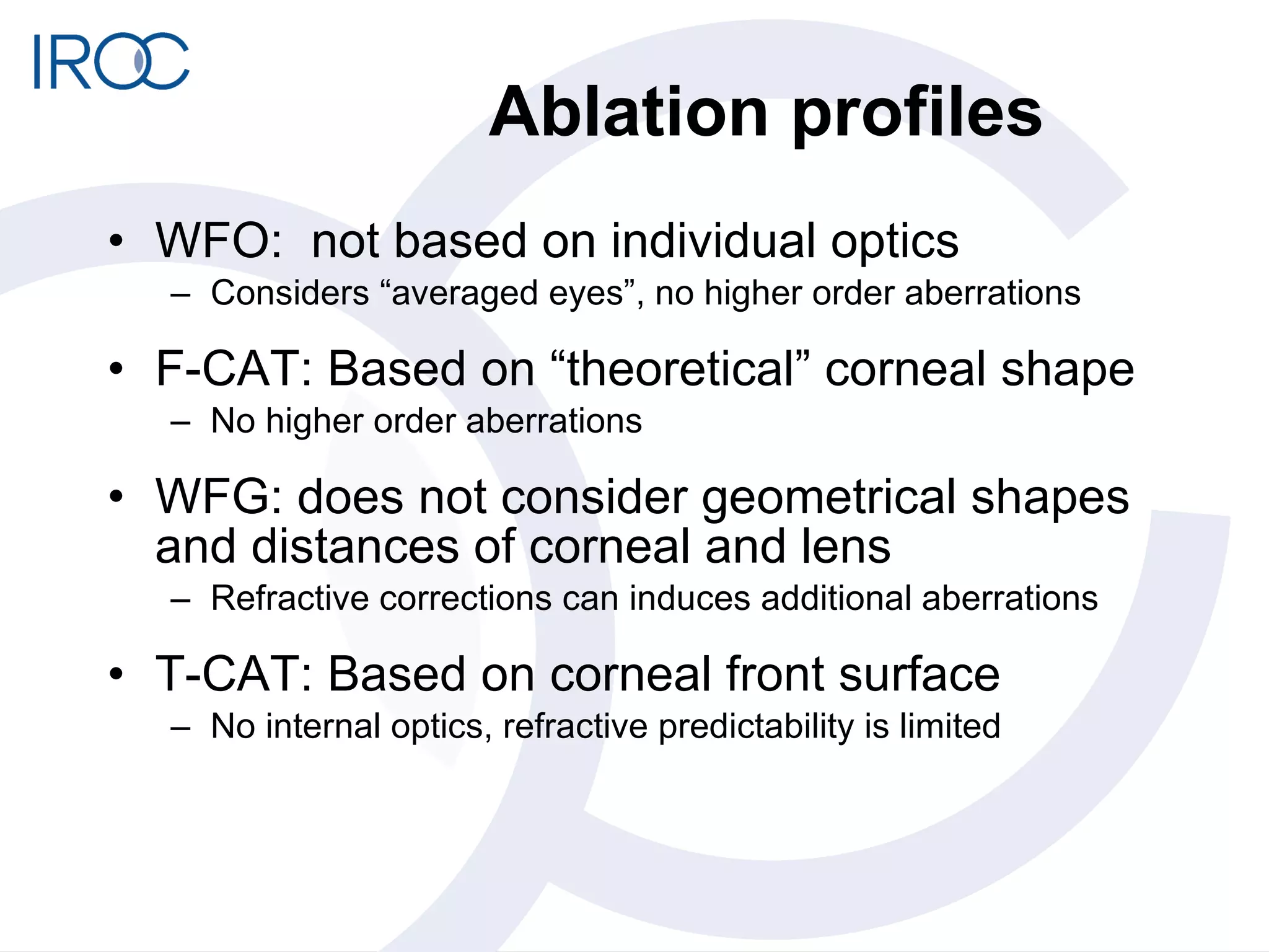
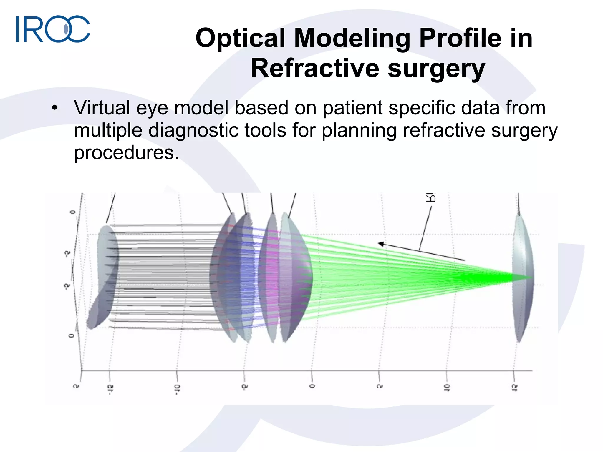
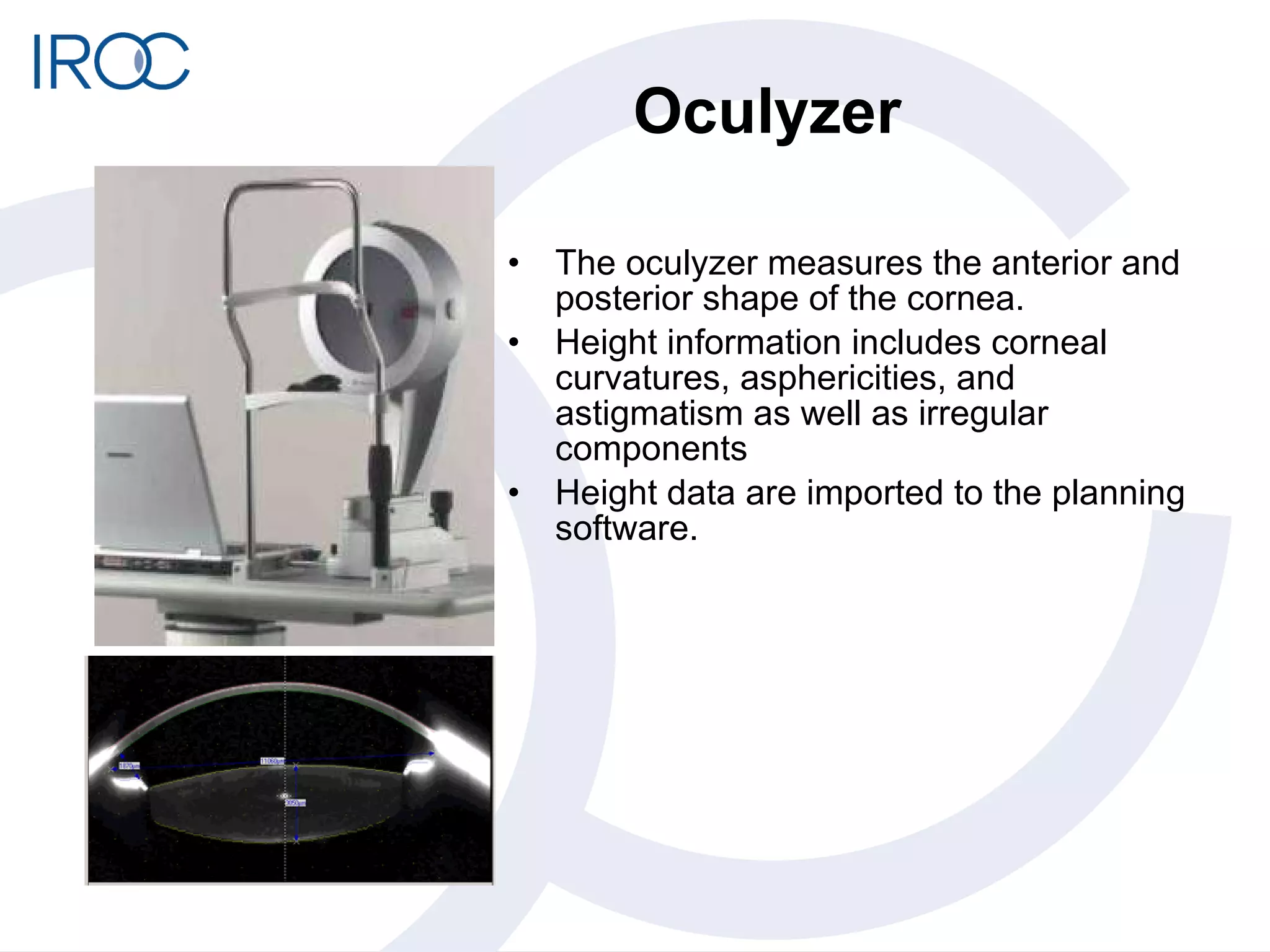
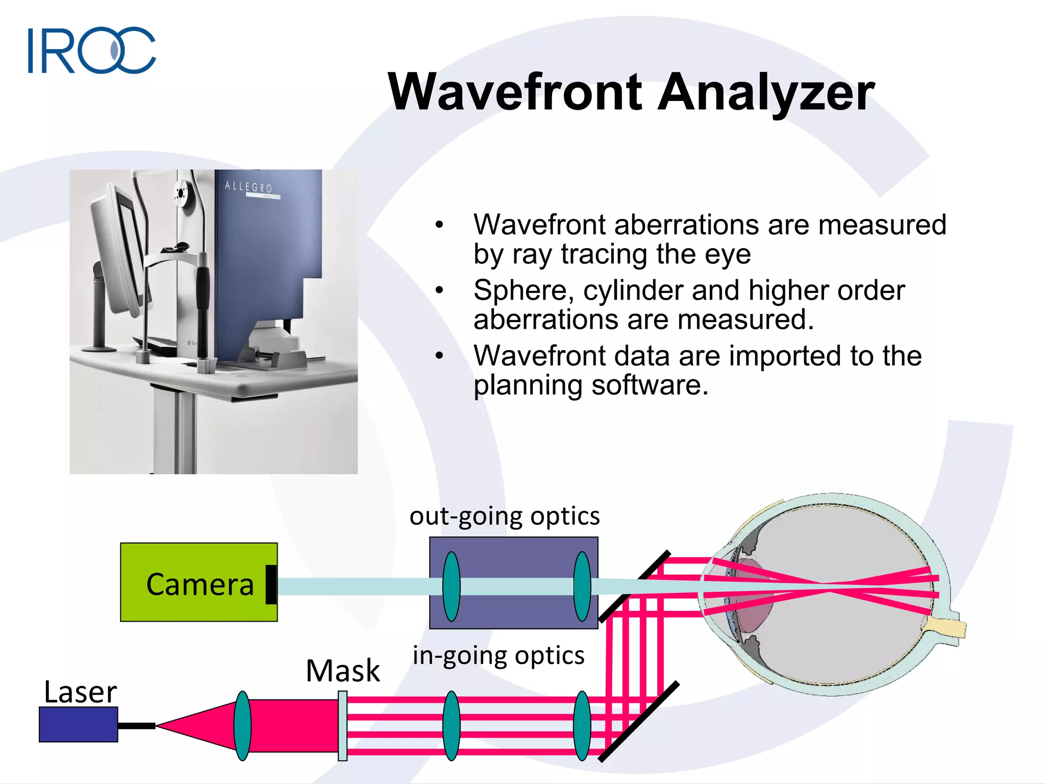
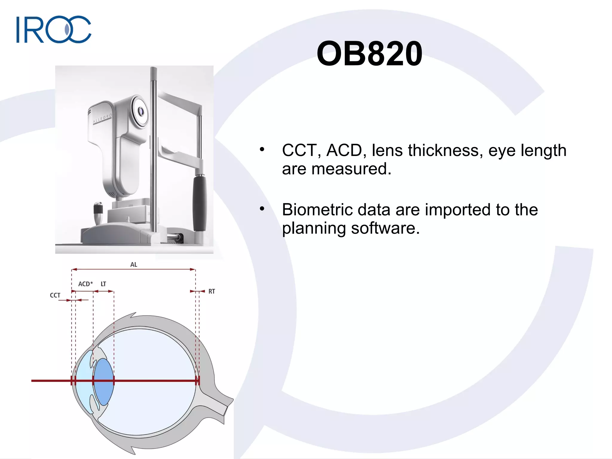
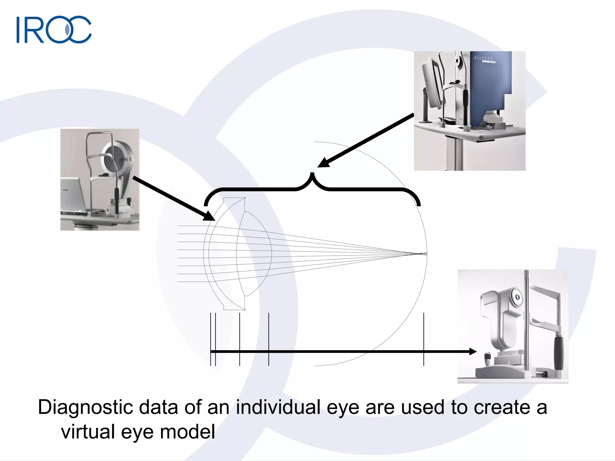
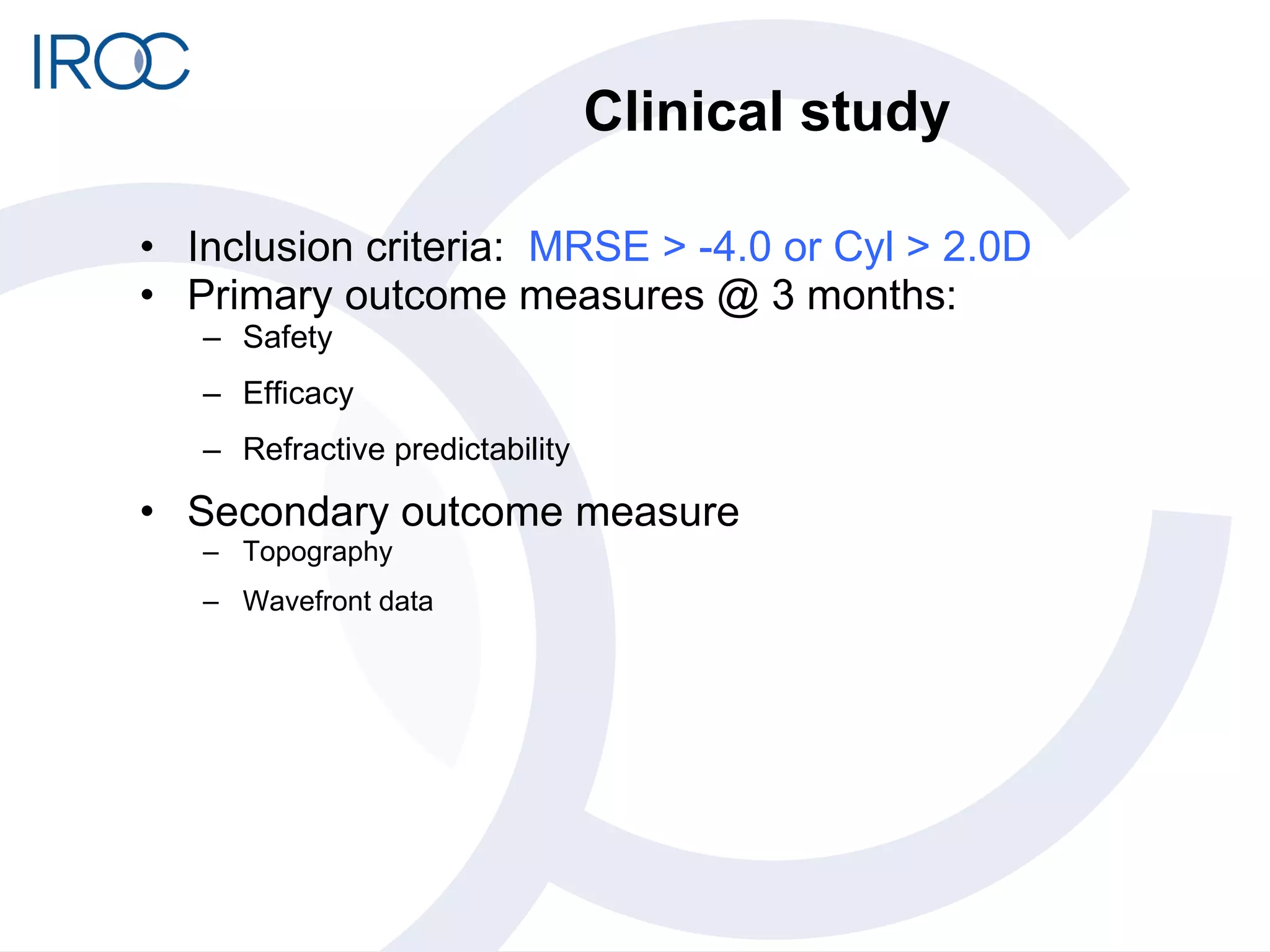
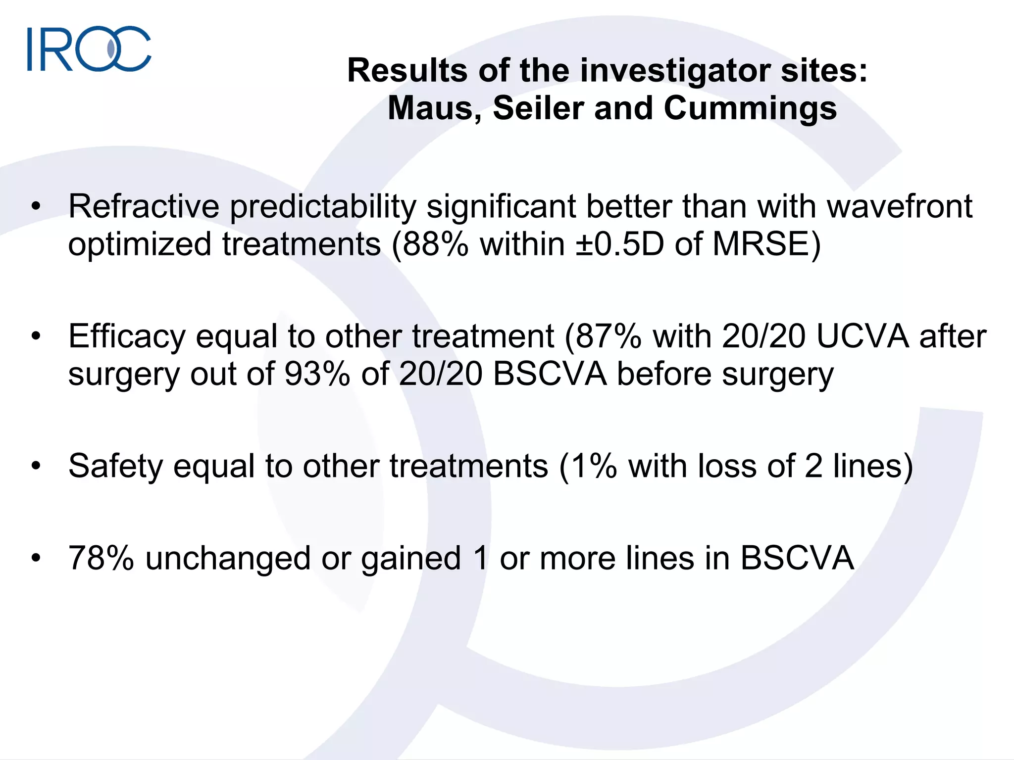
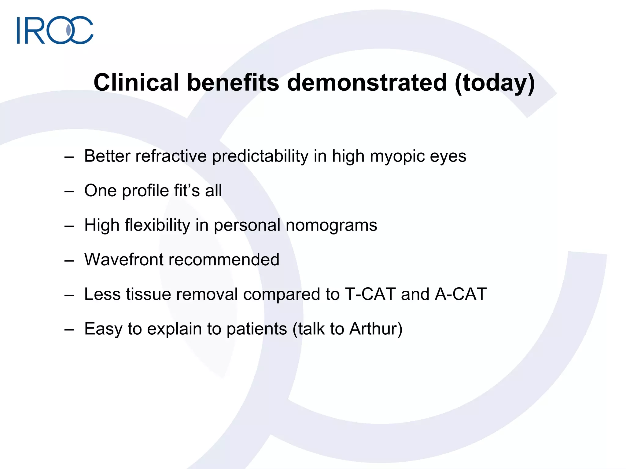
Optical Modeling Profile in  Refractive surgery Michael Mrochen, PhD IROC AG   Institut für Refraktive und Ophthalmo-Chirurgie Stockerstrasse 37 8002 Zürich WWW.IROC.CH
Ablation profiles WFO:  not based on individual optics Considers “averaged eyes”, no higher order aberrations F-CAT: Based on “theoretical” corneal shape No higher order aberrations WFG: does not consider geometrical shapes and distances of corneal and lens Refractive corrections can induces additional aberrations T-CAT: Based on corneal front surface No internal optics, refractive predictability is limited
Optical Modeling Profile in  Refractive surgery Virtual eye model based on patient specific data from multiple diagnostic tools for planning refractive surgery procedures.
Diagnostic data of an individual eye are used to create a virtual eye model
Oculyzer The oculyzer measures the anterior and posterior shape of the cornea. Height information includes corneal curvatures, asphericities, and astigmatism as well as irregular components Height data are imported to the planning software.
Wavefront Analyzer Wavefront aberrations are measured by ray tracing the eye Sphere, cylinder and higher order aberrations are measured. Wavefront data are imported to the planning software. Camera Laser Mask out-going optics in-going optics
OB820 CCT, ACD, lens thickness, eye length are measured. Biometric data are imported to the planning software.
Diagnostic data of an individual eye are used to create a virtual eye model
Thin lens optics Marginal ray Chief ray Object Image Focal length Pupil
Thin lens optics Objective Ocular Object Focal length Focal length Image
One refractive surface Air  n = 1 Cornea  n = 1.376 Radius of curvature R = 7.78 mm     Snell’s law Ray height Ray height Thickness of the surface New Ray  Heights
Two refractive surfaces     Thickness 1 Thickness 2 Refractive index  n=1.5 Refractive index  n=1.0 Refractive index  n=1.0 Radius of curvature R1 Radius of curvature R2
Example fish eye lens
Optical ray tracing Calculating the path of light through an optical system with regions of different thicknesses and refractive indices Ray tracing solves the problem by applying idealized narrow light beams called “rays” through discrete media.  Even very complex optical systems can be calculated by using a computer to propagate many rays.
Ray tracing the human eye CCT ACD LT PCD n c n ACD n L n PC R CF ,Q CF R CB ,Q CB R LF ,Q LF R LB ,Q LB
IOL power calculation
IOL position
Corneal laser surgery
Optical Modeling Profile in  Refractive surgery Create an individual eye model Software finds the best possible ablation profile  All available individual diagnostic data are used. A test treatment is simulated before it is transferred to the excimer laser
Clinical study Prospective clinical trail at 3 sites (Seiler, Maus,Cummings) 135 eyes included 3 months follow up. Patients were treated either with Ray tracing + corneal modeling Enhanced T-CAT + corneal modeling
Clinical study Inclusion criteria:  MRSE > -4.0 or Cyl > 2.0D Primary outcome measures @ 3 months: Safety Efficacy Refractive predictability Secondary outcome measure Topography  Wavefront data
Results of the investigator sites:  Maus, Seiler and Cummings Refractive predictability significant better than with wavefront optimized treatments (88% within  ±0.5D of MRSE) Efficacy equal to other treatment (87% with 20/20 UCVA after surgery out of 93% of 20/20 BSCVA before surgery  Safety equal to other treatments (1% with loss of 2 lines) 78% unchanged or gained 1 or more lines in BSCVA
 
Clinical benefits demonstrated (today) Better refractive predictability in high myopic eyes One profile fit’s all High flexibility in personal nomograms  Wavefront recommended Less tissue removal compared to T-CAT and A-CAT Easy to explain to patients (talk to Arthur)
Thank you

Optical modeling profile

  • 1.
    Optical Modeling Profilein Refractive surgery Michael Mrochen, PhD IROC AG Institut für Refraktive und Ophthalmo-Chirurgie Stockerstrasse 37 8002 Zürich WWW.IROC.CH
  • 2.
    Ablation profiles WFO: not based on individual optics Considers “averaged eyes”, no higher order aberrations F-CAT: Based on “theoretical” corneal shape No higher order aberrations WFG: does not consider geometrical shapes and distances of corneal and lens Refractive corrections can induces additional aberrations T-CAT: Based on corneal front surface No internal optics, refractive predictability is limited
  • 3.
    Optical Modeling Profilein Refractive surgery Virtual eye model based on patient specific data from multiple diagnostic tools for planning refractive surgery procedures.
  • 4.
    Diagnostic data ofan individual eye are used to create a virtual eye model
  • 5.
    Oculyzer The oculyzermeasures the anterior and posterior shape of the cornea. Height information includes corneal curvatures, asphericities, and astigmatism as well as irregular components Height data are imported to the planning software.
  • 6.
    Wavefront Analyzer Wavefrontaberrations are measured by ray tracing the eye Sphere, cylinder and higher order aberrations are measured. Wavefront data are imported to the planning software. Camera Laser Mask out-going optics in-going optics
  • 7.
    OB820 CCT, ACD,lens thickness, eye length are measured. Biometric data are imported to the planning software.
  • 8.
    Diagnostic data ofan individual eye are used to create a virtual eye model
  • 9.
    Thin lens opticsMarginal ray Chief ray Object Image Focal length Pupil
  • 10.
    Thin lens opticsObjective Ocular Object Focal length Focal length Image
  • 11.
    One refractive surfaceAir n = 1 Cornea n = 1.376 Radius of curvature R = 7.78 mm     Snell’s law Ray height Ray height Thickness of the surface New Ray Heights
  • 12.
    Two refractive surfaces    Thickness 1 Thickness 2 Refractive index n=1.5 Refractive index n=1.0 Refractive index n=1.0 Radius of curvature R1 Radius of curvature R2
  • 13.
  • 14.
    Optical ray tracingCalculating the path of light through an optical system with regions of different thicknesses and refractive indices Ray tracing solves the problem by applying idealized narrow light beams called “rays” through discrete media. Even very complex optical systems can be calculated by using a computer to propagate many rays.
  • 15.
    Ray tracing thehuman eye CCT ACD LT PCD n c n ACD n L n PC R CF ,Q CF R CB ,Q CB R LF ,Q LF R LB ,Q LB
  • 16.
  • 17.
  • 18.
  • 19.
    Optical Modeling Profilein Refractive surgery Create an individual eye model Software finds the best possible ablation profile All available individual diagnostic data are used. A test treatment is simulated before it is transferred to the excimer laser
  • 20.
    Clinical study Prospectiveclinical trail at 3 sites (Seiler, Maus,Cummings) 135 eyes included 3 months follow up. Patients were treated either with Ray tracing + corneal modeling Enhanced T-CAT + corneal modeling
  • 21.
    Clinical study Inclusioncriteria: MRSE > -4.0 or Cyl > 2.0D Primary outcome measures @ 3 months: Safety Efficacy Refractive predictability Secondary outcome measure Topography Wavefront data
  • 22.
    Results of theinvestigator sites: Maus, Seiler and Cummings Refractive predictability significant better than with wavefront optimized treatments (88% within ±0.5D of MRSE) Efficacy equal to other treatment (87% with 20/20 UCVA after surgery out of 93% of 20/20 BSCVA before surgery Safety equal to other treatments (1% with loss of 2 lines) 78% unchanged or gained 1 or more lines in BSCVA
  • 23.
  • 24.
    Clinical benefits demonstrated(today) Better refractive predictability in high myopic eyes One profile fit’s all High flexibility in personal nomograms Wavefront recommended Less tissue removal compared to T-CAT and A-CAT Easy to explain to patients (talk to Arthur)
  • 25.