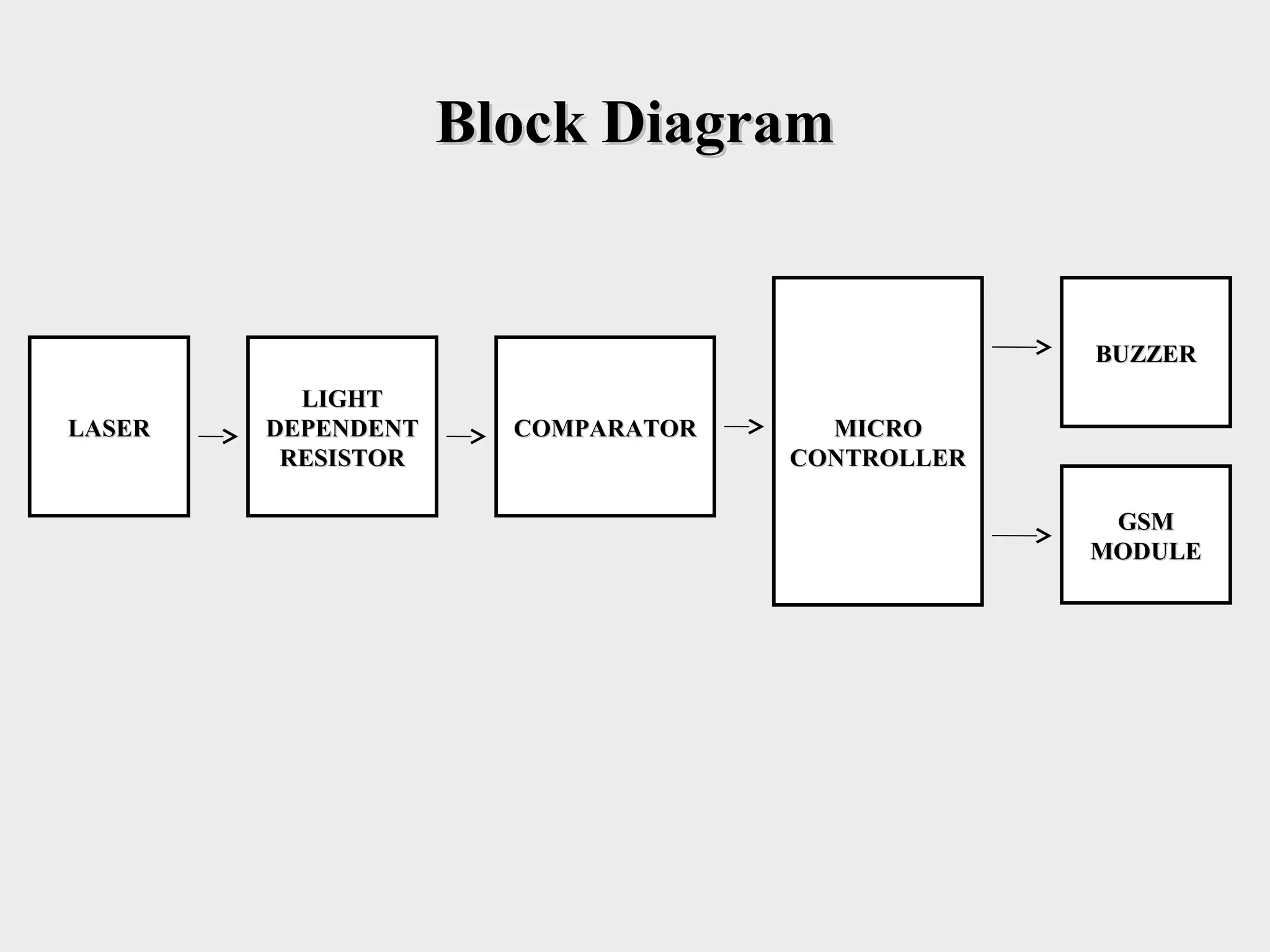
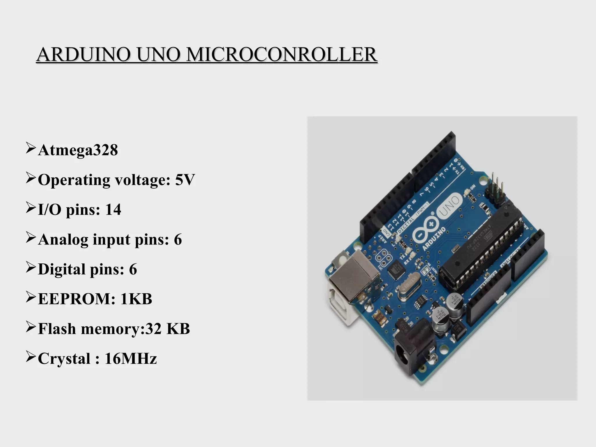
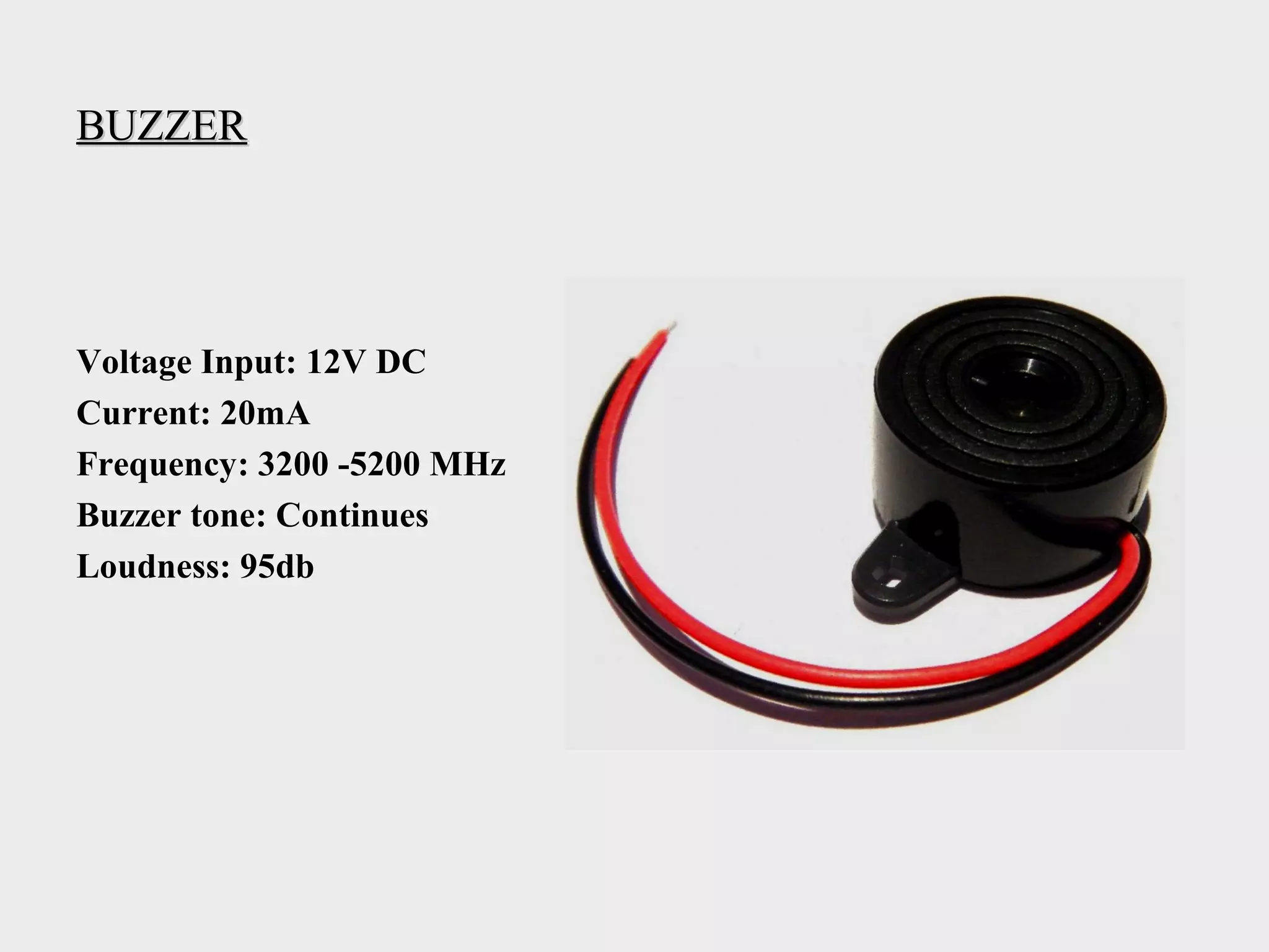
Optical Beam Security SystemOptical Beam Security System
• Optical beam based Security System is a type of securityOptical beam based Security System is a type of security
and alarm system that uses laser light and a light sensor. Aand alarm system that uses laser light and a light sensor. A
security system protects our homes, offices, banks, lockerssecurity system protects our homes, offices, banks, lockers
etc. from intrusion and unauthorised access. There areetc. from intrusion and unauthorised access. There are
different types of security systems available and opticaldifferent types of security systems available and optical
beam based security system is an important and efficientbeam based security system is an important and efficient
type.type.
• A optical beam security system can acts as a system, whichA optical beam security system can acts as a system, which
makes some sound or noise when it detects any irregularmakes some sound or noise when it detects any irregular
activity, or can be part of a much bigger security and homeactivity, or can be part of a much bigger security and home
automation system, which can send messages, call theautomation system, which can send messages, call the
owner etc.owner etc.
Block DiagramBlock Diagram
LASERLASER
LIGHTLIGHT
DEPENDENTDEPENDENT
RESISTORRESISTOR
COMPARATORCOMPARATOR MICROMICRO
CONTROLLERCONTROLLER
BUZZERBUZZER
GSMGSM
MODULEMODULE
Components SpecificationComponents Specification
LIGHT DEPENDENT RESISTORLIGHT DEPENDENT RESISTOR
Working Principle: Photoconductivity
Material: Semiconductor (Si, Ge, Sn)
Maximum Resistance :10kΩ
OPERATIONAL AMPLIFIER LM324OPERATIONAL AMPLIFIER LM324
Company: Texas instruments
Maximum supply voltage VCC: 3-32 volts
Temperature limit: 70˚ C
Input voltage range: 0.3-32 volts
ARDUINO UNO MICROCONROLLERARDUINO UNO MICROCONROLLER
Atmega328
Operating voltage: 5V
I/O pins: 14
Analog input pins: 6
Digital pins: 6
EEPROM: 1KB
Flash memory:32 KB
Crystal : 16MHz
BUZZERBUZZER
Voltage Input: 12V DC
Current: 20mA
Frequency: 3200 -5200 MHz
Buzzer tone: Continues
Loudness: 95db
GGloballobal SSystem forystem for MMobile Communicationobile Communication (GSM)(GSM) ModuleModule
GSM Module: SIM900
Frequency: 850/900/1800/1900 MHz
Interface: RS232 Serial Cable
Power requirement: 4.5-12 Volts
Temperature Range: -40 to 85 ˚C
Circuit DiagramCircuit Diagram
Working PrincipleWorking Principle
• First, the Op – Amp circuit acts as a comparator i.e. it compares theFirst, the Op – Amp circuit acts as a comparator i.e. it compares the
voltages at the inverting and non – inverting terminals and producesvoltages at the inverting and non – inverting terminals and produces
an output accordingly.an output accordingly.
• The LDR – 10 KΩ resistor Voltage divider is connected to the non –The LDR – 10 KΩ resistor Voltage divider is connected to the non –
inverting terminal of Op –Amp and a potentiometer is connected toinverting terminal of Op –Amp and a potentiometer is connected to
the inverting terminal.the inverting terminal.
• The optical beam pointer is placed directly in line of sight to theThe optical beam pointer is placed directly in line of sight to the
LDR and the light from the laser is continuously being incident onLDR and the light from the laser is continuously being incident on
LDR.LDR.
• When the interrupt occurs, the resistance of LDR falls down to fewWhen the interrupt occurs, the resistance of LDR falls down to few
Ohms and as a result, the voltage at the inverting terminal will beOhms and as a result, the voltage at the inverting terminal will be
more than that at the non-inverting voltage. The output of the Op –more than that at the non-inverting voltage. The output of the Op –
Amp is high and the microcontroller will on and according to theAmp is high and the microcontroller will on and according to the
output the buzzer will on and GSM module will make aware theoutput the buzzer will on and GSM module will make aware the
person by sending message on the registered mobile number.person by sending message on the registered mobile number.
Work DoneWork Done
AlgorithmAlgorithm
• Step 1: Initialization of PinsStep 1: Initialization of Pins
• Step 2: Monitor status of analog input pinsStep 2: Monitor status of analog input pins
• Step 3: If output is between 4 to 5.5 volts than go to stepStep 3: If output is between 4 to 5.5 volts than go to step
4, otherwise go to step 24, otherwise go to step 2
• Step 4: Send signal from microcontroller to ring theStep 4: Send signal from microcontroller to ring the
buzzer connected on digital output pins and sendbuzzer connected on digital output pins and send
message through GSM modulemessage through GSM module
ApplicationApplication
• This project is mainly used in security appliances to protect the
important and confidential documentary things against theft.
• Industrial use to count the number of goods.
• Thickness measurement
• Laser altimeter to provide route planning and crash avoidance aerial
vehicles.
• Level measurement
• Personal parking garage system
• Bridge public clearance
• Steel measurement
• Piled up ice cream cups
SummarySummary
• While preparing a optical beam security system, we need to
concentrate on the microcontroller program and installed
with the GSM module device. When using traditional photo
resistors for preparing security systems one has to consider
the natural light phenomena. Laser are strong in beam width
and can be focused on the perfect target. By using laser
security system one can be safe in the case of harmful
effects to the body. As the beam width used in the laser
security systems are not strong beam widths.
ReferenceReference
• http://www.electronicshub.org
• http://www.ti.com/lit/ds/symlink/lm224-n.pdf
• http://www.atmel.com/images/doc2503.pdf
• http://www.propox.com/download/docs/SIM900.pdf
optical beam security system

optical beam security system

  • 1.
    Optical Beam SecuritySystemOptical Beam Security System • Optical beam based Security System is a type of securityOptical beam based Security System is a type of security and alarm system that uses laser light and a light sensor. Aand alarm system that uses laser light and a light sensor. A security system protects our homes, offices, banks, lockerssecurity system protects our homes, offices, banks, lockers etc. from intrusion and unauthorised access. There areetc. from intrusion and unauthorised access. There are different types of security systems available and opticaldifferent types of security systems available and optical beam based security system is an important and efficientbeam based security system is an important and efficient type.type. • A optical beam security system can acts as a system, whichA optical beam security system can acts as a system, which makes some sound or noise when it detects any irregularmakes some sound or noise when it detects any irregular activity, or can be part of a much bigger security and homeactivity, or can be part of a much bigger security and home automation system, which can send messages, call theautomation system, which can send messages, call the owner etc.owner etc.
  • 2.
  • 3.
    Components SpecificationComponents Specification LIGHTDEPENDENT RESISTORLIGHT DEPENDENT RESISTOR Working Principle: Photoconductivity Material: Semiconductor (Si, Ge, Sn) Maximum Resistance :10kΩ
  • 4.
    OPERATIONAL AMPLIFIER LM324OPERATIONALAMPLIFIER LM324 Company: Texas instruments Maximum supply voltage VCC: 3-32 volts Temperature limit: 70˚ C Input voltage range: 0.3-32 volts
  • 5.
    ARDUINO UNO MICROCONROLLERARDUINOUNO MICROCONROLLER Atmega328 Operating voltage: 5V I/O pins: 14 Analog input pins: 6 Digital pins: 6 EEPROM: 1KB Flash memory:32 KB Crystal : 16MHz
  • 6.
    BUZZERBUZZER Voltage Input: 12VDC Current: 20mA Frequency: 3200 -5200 MHz Buzzer tone: Continues Loudness: 95db
  • 7.
    GGloballobal SSystem forystemfor MMobile Communicationobile Communication (GSM)(GSM) ModuleModule GSM Module: SIM900 Frequency: 850/900/1800/1900 MHz Interface: RS232 Serial Cable Power requirement: 4.5-12 Volts Temperature Range: -40 to 85 ˚C
  • 8.
  • 9.
    Working PrincipleWorking Principle •First, the Op – Amp circuit acts as a comparator i.e. it compares theFirst, the Op – Amp circuit acts as a comparator i.e. it compares the voltages at the inverting and non – inverting terminals and producesvoltages at the inverting and non – inverting terminals and produces an output accordingly.an output accordingly. • The LDR – 10 KΩ resistor Voltage divider is connected to the non –The LDR – 10 KΩ resistor Voltage divider is connected to the non – inverting terminal of Op –Amp and a potentiometer is connected toinverting terminal of Op –Amp and a potentiometer is connected to the inverting terminal.the inverting terminal. • The optical beam pointer is placed directly in line of sight to theThe optical beam pointer is placed directly in line of sight to the LDR and the light from the laser is continuously being incident onLDR and the light from the laser is continuously being incident on LDR.LDR. • When the interrupt occurs, the resistance of LDR falls down to fewWhen the interrupt occurs, the resistance of LDR falls down to few Ohms and as a result, the voltage at the inverting terminal will beOhms and as a result, the voltage at the inverting terminal will be more than that at the non-inverting voltage. The output of the Op –more than that at the non-inverting voltage. The output of the Op – Amp is high and the microcontroller will on and according to theAmp is high and the microcontroller will on and according to the output the buzzer will on and GSM module will make aware theoutput the buzzer will on and GSM module will make aware the person by sending message on the registered mobile number.person by sending message on the registered mobile number.
  • 10.
  • 11.
    AlgorithmAlgorithm • Step 1:Initialization of PinsStep 1: Initialization of Pins • Step 2: Monitor status of analog input pinsStep 2: Monitor status of analog input pins • Step 3: If output is between 4 to 5.5 volts than go to stepStep 3: If output is between 4 to 5.5 volts than go to step 4, otherwise go to step 24, otherwise go to step 2 • Step 4: Send signal from microcontroller to ring theStep 4: Send signal from microcontroller to ring the buzzer connected on digital output pins and sendbuzzer connected on digital output pins and send message through GSM modulemessage through GSM module
  • 12.
    ApplicationApplication • This projectis mainly used in security appliances to protect the important and confidential documentary things against theft. • Industrial use to count the number of goods. • Thickness measurement • Laser altimeter to provide route planning and crash avoidance aerial vehicles. • Level measurement • Personal parking garage system • Bridge public clearance • Steel measurement • Piled up ice cream cups
  • 13.
    SummarySummary • While preparinga optical beam security system, we need to concentrate on the microcontroller program and installed with the GSM module device. When using traditional photo resistors for preparing security systems one has to consider the natural light phenomena. Laser are strong in beam width and can be focused on the perfect target. By using laser security system one can be safe in the case of harmful effects to the body. As the beam width used in the laser security systems are not strong beam widths.
  • 14.
    ReferenceReference • http://www.electronicshub.org • http://www.ti.com/lit/ds/symlink/lm224-n.pdf •http://www.atmel.com/images/doc2503.pdf • http://www.propox.com/download/docs/SIM900.pdf