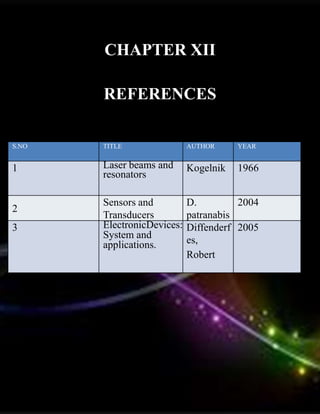
TITLE OF THE PROJECT
Laser Security System
INTRODUCTION TO
ENGINEERING REPORT
Submitted by
V. HARSHA VARDHAN 22527
S. MOHAN KRISHNA 23226
CH. AVINASH REDDY 23033
S. MADIHA SULTANA 22986
R. THANMAYEE 23262
S.P . GOWTHAMI 22724
FRESHMAN ENGINEERING
VEL TECH RANGARAJAN DR.SAGUNTHALA R&D
INSTITUTE OF
SCIENCE AND TECHNOLOGY
DECEMBER 2022
VEL TECH RANGARAJAN DR.SAGUNTHALA R&D
INSTITUTE OF SCIENCE AND TECHNOLOGY
CHENNAI 600 062
BONAFIDE CERTIFICATE
Certified that this project “Laser Security System”
is the bonafide work of V. HARSHA VARDHAN (22527)
who carried out this project work under my supervision.
SIGNATURE
HOD
SIGNATURE
PROJECT COORDINATOR
Faculty name:Mr.K.THANIGAIVEL
Designation: Assistant professor
Department: EEE
The Examination is held on
EXAMINER 1 EXAMINER 2
1. AGRICULTURE
2. PUBLIC SAFETY
3. WASTE TO WEALTH
4. ENERGY CONSERVATION
5. ENVIRONMENTAL
CONSERVATION
6. ROBOTICS
7. INFRASTRUCTURE
8. TRANSPORTATION
9. BIO ENGINEERING
10. RENEWABLE ENERGY
List of themes
TABLE OF CONTENTS
CHAPTER NO. TITLE
LIST OF FIGURES v
LIST OF
ABBREVIATIONS
v
1 INTRODUCTION 1
2 EXISTING SYSTEM 2
3
PROBLEM
IDENTIFICATION
3
4 PROPOSED SYSTEM 4
5 BLOCK DIAGRAM 5
6 CIRCUIT DESIGN 6
7
MATERIALS AND
METHODS
7
8 WORKING 10
9
HARDWARE
DISSCUSSION
11
10
ADVANTAGES AND
LIMITATIONS
12
11 CONCLUSION 14
12 REFERENCE 15
13 LITERATURE SURVEY 16
LIST OF FIGURES
FIGURE NO TITLE PAGE NO
1. Block Diagram
2. Circuit Design
3. Laser Pointer
4. Light Dependent Resistor
5.
NE555
6. LM358
7. Hardware Discussion
8. ESP-32 CAMERA
SYMBOLS
LIST OF ABBREVIATIONS
ABBREVIATIONS
1. LDR Light Dependent Resistor
2. NPN Negative,Positive,Negative
INTRODUCTION
Laser Security System is very
useful in high command security place. In a high secured
place where nobody is allowed to enter we can install it.
These are easy to install and work at both within as well as
outside houses. These are very effective perimeter alarm
systems around properties. In indoor systems can utilize
the normal power outlets and jacks making them
inconspicuous. At outside these can be easily be hidden
behind the bushes or plants without causing any damage.
They consume less power when compared to the laser
system as the whole, which is expensive. These laser
systems can be installed in homes either by self or by
hiring a technical person. By technological innovations
cost of the security systems has been cut to a large extent.
So, making laser systems one among affordable security
system options can be very safe. It has ability to work
continuously; it is not only human but also a small animal
or any other movable objects. Its alarming Sound does not
stop until anybody stops it after checking. Now we can use
this system in a wide range of area.
CHAPTER I
CHAPTER II
EXISTING SYSTEM
Laser based Security
System is a type of security and alarm system that
uses laser light and a light sensor. A security system
protects our homes, offices, banks, lockers etc. from
intrusion and unauthorised access. There are different
types of security systems available and laser based
security system is an important and efficient type. A
Laser security system can acts as a standalone system,
which makes some sound or noise when it detects any
irregular activity, or can be part of a much bigger
security and home automation system, which can send
messages, call the owner etc. In this project, we have
designed a simple DIY lased based security system,
which acts as a tripwire like security system and
triggers an alarm when the laser in interrupted.
PROBLEM IDENTIFICATION
The problems we identified in this project are.
1. To supply required voltage.
2. In laser pointer the wavelength of the laser output.
Solutions that we identified:
1. Using Voltage Regulator.
2. In laser pointer the wavelength is 630 nm to
680 nm.
CHAPTER III
PROPOSED SYSTEM
Laser based Security System is a type of
security and alarm system that uses laser light and a light
sensor. A security system protects our homes, offices, banks,
lockers etc. from intrusion and unauthorised access. There are
different types of security systems available and laser based
security system is an important and efficient type.A Laser
security system can acts as a standalone system, which makes
some sound or noise when it detects any irregular activity, or
can be part of a much bigger security and home automation
system, which can send messages, call the owner etc.In this
project, we have designed a simple DIY lased based security
system, which acts as a tripwire like security system and
triggers an alarm when the laser in interrupted.
CHAPTER IV
BLOCK DIAGRAM
CHAPTER V
CIRCUITDESIGN
CHAPTER VI
CHAPTER VII
MATERIALS
1 . LDR
2 . Small Buzzer
3 . Push Button
4 . Laser Pointer 5.9V Battery
6 . Connecting Wires
7 . Breadboard (Prototyping board)
8 . LM358 (Op - Amp IC)
9 . NE555 (Timer IC)
10. BC547 (NPN Transistor)
11. 100 nF Capacitor (Ceramic Disc
Type Capacitor - Code 104)
12. 3 x 10 KQ Resistors (1/4 Watt)
13. 220 Q Resistors (1/4 Watt)
14. 10 KQ Potentiometer
15. ESP-32 CAMERA
COMPONENT DESCRIPTION
Laser Pointer
Laser Pointer acts as the main source of light in this project. We have used a small laser
pointer with an output power of less than 1mW. The laser pointer emits red light and the
wavelength of the laser output is between 630 nm to 680 nm.
LDR (Light Dependent Resistor)
The LDR acts as a light sensor in this project. As the intensity of the light falling on the
LDR increases, the resistance of the LDR decreases and vice - versa. The LDR is used in
combination with the laser to form the light sensor and source.
NE555 (IC 555)
IC 555 is a precision timing IC that provides
time delays or oscillations. 555 Timer IC has
three modes of operation: Astable, Monostable
and Bi-stable. In this project, we are going to use
the IC 555 in Bi-stable mode.
LM358 (OP - Amp)
LM358 is a dual Operational Amplifier IC and it
is capable of operating in all the conventional
operational amplifier circuits. In this project, the
LM358 is used as a Comparator.
CHAPTER VIII
WORKING
This circuit is based on LDR (Light Depended
Resistor), a variable resistor in which the resistance varies according to the
light intensity falling on it. The LDR and resistor RI forms a potential
divider network, which is the main part of our security alarm circuit. The
voltage drop across the LDR is used to drive the transistor switch. When
the voltage drop is above cut in voltage (0.6 V), the transistor is turned
ON. LDR has low resistance (ms2 range) in the presence of light and high
resistance (M.2 range) in the absence of light. We have already discussed
about how transistor acts as a switch, the same principle is used here.
Light from other sources should not be allowed to fall on a box with a
single hole o pass LASER. This the resistance offered by LDR is too low,
since the LASER light is continuously allowed to fall on the LDR surface.
Thus the voltage drop across the LDR is also low [V-IR (Ohm's law)]
which is insufficient to turn ON the transistor, so the transistor remains in
OFF state. When a person (EG thief) makes a block to the continuous
flow of LASER beam, then the light falling on the LDR gets blocked.
Thus its resistance increases to a high value in the order of M2 range
(According to Ohm's law V-IR). While resistance increases the voltage
drop also increases when this voltage drop exceeds the cut in voltage of
the silicon NPN transistor (2N7000), it will turn ON. Then current from
VCC starts flowing to ground via the buzzer and transistor, which makes
the beep sound. The beep sound from the security alarm gives the
indication of some security failures.
CHAPTER IX
HARDWARE DISCUSSION
CHAPTER X
ADVANTAGES
■ To protect home and
industry.
■ Easy to construct, parts of
the circuit are easily available.
■ It reduced the man's effort.
■ Accuracy of this circuit is
more than accuracy of other
circuits.
■ The cost of circuit is low.
■ They need very small power
and voltage for its operation.
■ Two operational amplifiers
are compensated internally.
DISADVANTAGES
■ Highly inaccurate with a response time of
about tens or hundreds of milliseconds.
■ Unnecessary disturbances may occur
while using in the apartments
■ It is difficult to work with this equipment
if there are no sufficient lightning
conditions.
APPLICATIONS
■ Used for home security.
■ Used in the banks as a burglar alarm.
■ It an be used in jail to prevent prison break
■
Used as automatic indicator.
CHAPTER XI
CONCLUSION
In the end, we made the
laser security in low budget. It had been protect
in full security. Laser security systems are a high
tech technology that used to be a part of home
security only available to the wealthy. It is
manually switch dependent sensors and a basic
alarm unit. Laser security system a person
moves in front of the motion sensor, that
person’s body heat triggers the system’s alarm.
And the alarm signals the security monitoring
company and local law enforcement. The basic
alarm unit will also sound a loud alarm.
CHAPTER XII
REFERENCES
S.NO TITLE AUTHOR YEAR
1 Laser beams and
resonators
Kogelnik 1966
2
Sensors and
Transducers
D.
patranabis
2004
3 ElectronicDevices:
System and
applications.
Diffenderf
es,
Robert
2005
LITERATURE SURVEY
Website link for Laser
httns://www.electronicshu
b.or2/laser-security-
Security System system/
YouTube link
https: //youtu.be/8LbF 21
HKvuQ
Pdf link httos://www.iiser.
org/researchnaoer/LASER-
SECURITY-SYSTEM-
Suman.ndf
CHAPTER XIII
LIST OF MODELS
Carpentry:
- CRANK AND
SLOTTED
Electronics:
- EMERGENCY
LIGHT
Machine Shop:
- Sheet
metal tray
CARPENTRY : WOODEN WINDOW
AIM : To design Wooden Window as per the
required dimensions from the given work piece
APPARATUS:
• Wooden pieces
• Wood cutter
• Hammer
• Nuts, Bolts
• Screw driver
PROCEDURE:
o Take the wood
o Mark the measurements as shown in the below
design. o Cut the wood as per required
measurements with the help of wood cutter.
o By using the cut pieces of the wood make a
frame with the help of nails and hammer.
o Now take the wooden sheet as per the
measurements and fix it to the frame with the
help of nails and hammer.
MODEL 1
RESULT :
The design of wooden window as per the given
dimensions have successfully completed. From this model
I learnt how to make a wooden window with simple
instruments.
DIAGRAM :
ELECTRONICS: EMERGENCY LIGHT
AIM :To fabricate single side PCB for Emergency
Light MATERIALS REQUIRED :
> Single side copper clad PCB
> Digital multimeter (DMM)
> Ferric chloride solution and silicon carbride paper
> Drilling machine
> Soldering iron
PROCEDURE:
• For PCB design!1. Scratch the copper board using sand paper. But
make sure that you do not scratch it too hard or too much and also ensure
that sand paper is not too harder one After scratching clean the surface of
copper board
.2. Take the printout of PCB design layout in transparent paper, keep it on
copper board and iron it using ison. Ikon it well, make sure keep printed
side on the copper board.
3. After isoning it can be seen that the circuit diagramwill be printed on
copper board especially if properly done. But it may not be printed well
on the copper board especially if photocopied one is used. So with the
help of permanant macker pen draw the parts of circuit diagram which
aren't printed properly. Keep in mind to choose a marker with a small
point, otherwise it will be difficult draw.
•
MODEL 2
COMPONENTS REQURIED :
 DIODES
 CAPACITOR
 TRANSFOMER
 LED
4. Now you got a circuit diagram printed on copper board Take ferric
chloride and mix it with water. Put the copper board and wash it well-
copper will read with fessic chloride and finally you will get your
PCB. You will see the circuit diagrom on board in black colour
5. Wash the board using thinner and clean it Now youwill see your PCB
6. Using drilling machine make holes in the copper beardfor
introducing the components.
7. Connect the components using soldering iron
DIAGRAM :
TESTING
Using digital multimeter ,in continuity mode , test for continuity of
tracks and short circuit
RESULT :
As per the procedure emergency light is made
MODEL 3
MACHINE SHOP: SHEET
METAL TRAY
AIM : To prepare a Sheet Metal Tray
APPARATUS:
PROCEDURE :
> Metal sheet
> Metal cutter
> Hammer
> Scissors
> Scale
> Pencil
o Take a rectangular metal sheet
o Take the given measurements with the help of scale and pencil is
given in the above design
o Now cut the sheet through the marked measurements with the help
of scissors
o Bend the rest of the sheet
o Now attach the parts of the sheet and rub the sheet
with the help of scrubber to get it smoother
DIAGRAM :
RESULT : The design of the sheet metal tray as per the given
dimensions have successfully completed. From this
model I have learnt how to do a tray by using
simple instruments

laser light security system using camera

  • 1.
    TITLE OF THEPROJECT Laser Security System INTRODUCTION TO ENGINEERING REPORT Submitted by V. HARSHA VARDHAN 22527 S. MOHAN KRISHNA 23226 CH. AVINASH REDDY 23033 S. MADIHA SULTANA 22986 R. THANMAYEE 23262 S.P . GOWTHAMI 22724 FRESHMAN ENGINEERING
  • 2.
    VEL TECH RANGARAJANDR.SAGUNTHALA R&D INSTITUTE OF SCIENCE AND TECHNOLOGY DECEMBER 2022 VEL TECH RANGARAJAN DR.SAGUNTHALA R&D INSTITUTE OF SCIENCE AND TECHNOLOGY CHENNAI 600 062 BONAFIDE CERTIFICATE Certified that this project “Laser Security System” is the bonafide work of V. HARSHA VARDHAN (22527) who carried out this project work under my supervision. SIGNATURE HOD SIGNATURE PROJECT COORDINATOR Faculty name:Mr.K.THANIGAIVEL Designation: Assistant professor Department: EEE The Examination is held on EXAMINER 1 EXAMINER 2
  • 3.
    1. AGRICULTURE 2. PUBLICSAFETY 3. WASTE TO WEALTH 4. ENERGY CONSERVATION 5. ENVIRONMENTAL CONSERVATION 6. ROBOTICS 7. INFRASTRUCTURE 8. TRANSPORTATION 9. BIO ENGINEERING 10. RENEWABLE ENERGY List of themes
  • 4.
    TABLE OF CONTENTS CHAPTERNO. TITLE LIST OF FIGURES v LIST OF ABBREVIATIONS v 1 INTRODUCTION 1 2 EXISTING SYSTEM 2 3 PROBLEM IDENTIFICATION 3 4 PROPOSED SYSTEM 4 5 BLOCK DIAGRAM 5 6 CIRCUIT DESIGN 6 7 MATERIALS AND METHODS 7 8 WORKING 10 9 HARDWARE DISSCUSSION 11 10 ADVANTAGES AND LIMITATIONS 12 11 CONCLUSION 14 12 REFERENCE 15 13 LITERATURE SURVEY 16 LIST OF FIGURES FIGURE NO TITLE PAGE NO
  • 5.
    1. Block Diagram 2.Circuit Design 3. Laser Pointer 4. Light Dependent Resistor 5. NE555 6. LM358 7. Hardware Discussion 8. ESP-32 CAMERA SYMBOLS LIST OF ABBREVIATIONS ABBREVIATIONS 1. LDR Light Dependent Resistor 2. NPN Negative,Positive,Negative
  • 6.
    INTRODUCTION Laser Security Systemis very useful in high command security place. In a high secured place where nobody is allowed to enter we can install it. These are easy to install and work at both within as well as outside houses. These are very effective perimeter alarm systems around properties. In indoor systems can utilize the normal power outlets and jacks making them inconspicuous. At outside these can be easily be hidden behind the bushes or plants without causing any damage. They consume less power when compared to the laser system as the whole, which is expensive. These laser systems can be installed in homes either by self or by hiring a technical person. By technological innovations cost of the security systems has been cut to a large extent. So, making laser systems one among affordable security system options can be very safe. It has ability to work continuously; it is not only human but also a small animal or any other movable objects. Its alarming Sound does not stop until anybody stops it after checking. Now we can use this system in a wide range of area. CHAPTER I
  • 7.
    CHAPTER II EXISTING SYSTEM Laserbased Security System is a type of security and alarm system that uses laser light and a light sensor. A security system protects our homes, offices, banks, lockers etc. from intrusion and unauthorised access. There are different types of security systems available and laser based security system is an important and efficient type. A Laser security system can acts as a standalone system, which makes some sound or noise when it detects any irregular activity, or can be part of a much bigger security and home automation system, which can send messages, call the owner etc. In this project, we have designed a simple DIY lased based security system, which acts as a tripwire like security system and triggers an alarm when the laser in interrupted.
  • 8.
    PROBLEM IDENTIFICATION The problemswe identified in this project are. 1. To supply required voltage. 2. In laser pointer the wavelength of the laser output. Solutions that we identified: 1. Using Voltage Regulator. 2. In laser pointer the wavelength is 630 nm to 680 nm. CHAPTER III
  • 9.
    PROPOSED SYSTEM Laser basedSecurity System is a type of security and alarm system that uses laser light and a light sensor. A security system protects our homes, offices, banks, lockers etc. from intrusion and unauthorised access. There are different types of security systems available and laser based security system is an important and efficient type.A Laser security system can acts as a standalone system, which makes some sound or noise when it detects any irregular activity, or can be part of a much bigger security and home automation system, which can send messages, call the owner etc.In this project, we have designed a simple DIY lased based security system, which acts as a tripwire like security system and triggers an alarm when the laser in interrupted. CHAPTER IV
  • 10.
  • 11.
  • 12.
    CHAPTER VII MATERIALS 1 .LDR 2 . Small Buzzer 3 . Push Button 4 . Laser Pointer 5.9V Battery 6 . Connecting Wires 7 . Breadboard (Prototyping board) 8 . LM358 (Op - Amp IC) 9 . NE555 (Timer IC) 10. BC547 (NPN Transistor) 11. 100 nF Capacitor (Ceramic Disc Type Capacitor - Code 104) 12. 3 x 10 KQ Resistors (1/4 Watt) 13. 220 Q Resistors (1/4 Watt) 14. 10 KQ Potentiometer 15. ESP-32 CAMERA
  • 13.
    COMPONENT DESCRIPTION Laser Pointer LaserPointer acts as the main source of light in this project. We have used a small laser pointer with an output power of less than 1mW. The laser pointer emits red light and the wavelength of the laser output is between 630 nm to 680 nm. LDR (Light Dependent Resistor) The LDR acts as a light sensor in this project. As the intensity of the light falling on the LDR increases, the resistance of the LDR decreases and vice - versa. The LDR is used in combination with the laser to form the light sensor and source.
  • 14.
    NE555 (IC 555) IC555 is a precision timing IC that provides time delays or oscillations. 555 Timer IC has three modes of operation: Astable, Monostable and Bi-stable. In this project, we are going to use the IC 555 in Bi-stable mode. LM358 (OP - Amp) LM358 is a dual Operational Amplifier IC and it is capable of operating in all the conventional operational amplifier circuits. In this project, the LM358 is used as a Comparator.
  • 15.
    CHAPTER VIII WORKING This circuitis based on LDR (Light Depended Resistor), a variable resistor in which the resistance varies according to the light intensity falling on it. The LDR and resistor RI forms a potential divider network, which is the main part of our security alarm circuit. The voltage drop across the LDR is used to drive the transistor switch. When the voltage drop is above cut in voltage (0.6 V), the transistor is turned ON. LDR has low resistance (ms2 range) in the presence of light and high resistance (M.2 range) in the absence of light. We have already discussed about how transistor acts as a switch, the same principle is used here. Light from other sources should not be allowed to fall on a box with a single hole o pass LASER. This the resistance offered by LDR is too low, since the LASER light is continuously allowed to fall on the LDR surface. Thus the voltage drop across the LDR is also low [V-IR (Ohm's law)] which is insufficient to turn ON the transistor, so the transistor remains in OFF state. When a person (EG thief) makes a block to the continuous flow of LASER beam, then the light falling on the LDR gets blocked. Thus its resistance increases to a high value in the order of M2 range (According to Ohm's law V-IR). While resistance increases the voltage drop also increases when this voltage drop exceeds the cut in voltage of the silicon NPN transistor (2N7000), it will turn ON. Then current from VCC starts flowing to ground via the buzzer and transistor, which makes the beep sound. The beep sound from the security alarm gives the indication of some security failures.
  • 16.
  • 17.
    CHAPTER X ADVANTAGES ■ Toprotect home and industry. ■ Easy to construct, parts of the circuit are easily available. ■ It reduced the man's effort. ■ Accuracy of this circuit is more than accuracy of other circuits. ■ The cost of circuit is low. ■ They need very small power and voltage for its operation. ■ Two operational amplifiers are compensated internally.
  • 18.
    DISADVANTAGES ■ Highly inaccuratewith a response time of about tens or hundreds of milliseconds. ■ Unnecessary disturbances may occur while using in the apartments ■ It is difficult to work with this equipment if there are no sufficient lightning conditions. APPLICATIONS ■ Used for home security. ■ Used in the banks as a burglar alarm. ■ It an be used in jail to prevent prison break ■ Used as automatic indicator.
  • 19.
    CHAPTER XI CONCLUSION In theend, we made the laser security in low budget. It had been protect in full security. Laser security systems are a high tech technology that used to be a part of home security only available to the wealthy. It is manually switch dependent sensors and a basic alarm unit. Laser security system a person moves in front of the motion sensor, that person’s body heat triggers the system’s alarm. And the alarm signals the security monitoring company and local law enforcement. The basic alarm unit will also sound a loud alarm.
  • 20.
    CHAPTER XII REFERENCES S.NO TITLEAUTHOR YEAR 1 Laser beams and resonators Kogelnik 1966 2 Sensors and Transducers D. patranabis 2004 3 ElectronicDevices: System and applications. Diffenderf es, Robert 2005
  • 21.
    LITERATURE SURVEY Website linkfor Laser httns://www.electronicshu b.or2/laser-security- Security System system/ YouTube link https: //youtu.be/8LbF 21 HKvuQ Pdf link httos://www.iiser. org/researchnaoer/LASER- SECURITY-SYSTEM- Suman.ndf
  • 22.
    CHAPTER XIII LIST OFMODELS Carpentry: - CRANK AND SLOTTED Electronics: - EMERGENCY LIGHT Machine Shop: - Sheet metal tray
  • 23.
    CARPENTRY : WOODENWINDOW AIM : To design Wooden Window as per the required dimensions from the given work piece APPARATUS: • Wooden pieces • Wood cutter • Hammer • Nuts, Bolts • Screw driver PROCEDURE: o Take the wood o Mark the measurements as shown in the below design. o Cut the wood as per required measurements with the help of wood cutter. o By using the cut pieces of the wood make a frame with the help of nails and hammer. o Now take the wooden sheet as per the measurements and fix it to the frame with the help of nails and hammer. MODEL 1
  • 24.
    RESULT : The designof wooden window as per the given dimensions have successfully completed. From this model I learnt how to make a wooden window with simple instruments. DIAGRAM :
  • 25.
    ELECTRONICS: EMERGENCY LIGHT AIM:To fabricate single side PCB for Emergency Light MATERIALS REQUIRED : > Single side copper clad PCB > Digital multimeter (DMM) > Ferric chloride solution and silicon carbride paper > Drilling machine > Soldering iron PROCEDURE: • For PCB design!1. Scratch the copper board using sand paper. But make sure that you do not scratch it too hard or too much and also ensure that sand paper is not too harder one After scratching clean the surface of copper board .2. Take the printout of PCB design layout in transparent paper, keep it on copper board and iron it using ison. Ikon it well, make sure keep printed side on the copper board. 3. After isoning it can be seen that the circuit diagramwill be printed on copper board especially if properly done. But it may not be printed well on the copper board especially if photocopied one is used. So with the help of permanant macker pen draw the parts of circuit diagram which aren't printed properly. Keep in mind to choose a marker with a small point, otherwise it will be difficult draw. • MODEL 2 COMPONENTS REQURIED :  DIODES  CAPACITOR  TRANSFOMER  LED
  • 26.
    4. Now yougot a circuit diagram printed on copper board Take ferric chloride and mix it with water. Put the copper board and wash it well- copper will read with fessic chloride and finally you will get your PCB. You will see the circuit diagrom on board in black colour 5. Wash the board using thinner and clean it Now youwill see your PCB 6. Using drilling machine make holes in the copper beardfor introducing the components. 7. Connect the components using soldering iron DIAGRAM : TESTING Using digital multimeter ,in continuity mode , test for continuity of tracks and short circuit RESULT : As per the procedure emergency light is made
  • 27.
    MODEL 3 MACHINE SHOP:SHEET METAL TRAY AIM : To prepare a Sheet Metal Tray APPARATUS: PROCEDURE : > Metal sheet > Metal cutter > Hammer > Scissors > Scale > Pencil o Take a rectangular metal sheet o Take the given measurements with the help of scale and pencil is given in the above design o Now cut the sheet through the marked measurements with the help of scissors o Bend the rest of the sheet
  • 28.
    o Now attachthe parts of the sheet and rub the sheet with the help of scrubber to get it smoother DIAGRAM : RESULT : The design of the sheet metal tray as per the given dimensions have successfully completed. From this model I have learnt how to do a tray by using simple instruments