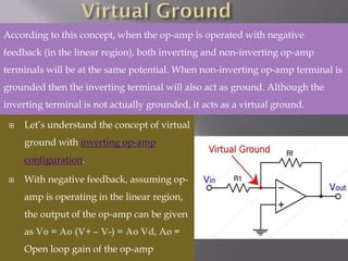
Let’s understandthe concept of virtual
ground with inverting op-amp
configuration.
With negative feedback, assuming op-
amp is operating in the linear region,
the output of the op-amp can be given
as Vo = Ao (V+ – V-) = Ao Vd, Ao =
Open loop gain of the op-amp
According to this concept, when the op-amp is operated with negative
feedback (in the linear region), both inverting and non-inverting op-amp
terminals will be at the same potential. When non-inverting op-amp terminal is
grounded then the inverting terminal will also act as ground. Although the
inverting terminal is not actually grounded, it acts as a virtual ground.
8.
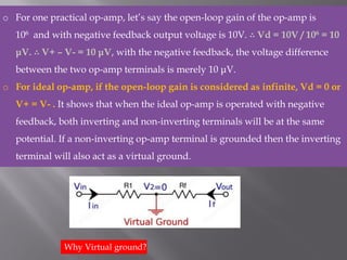
o For onepractical op-amp, let’s say the open-loop gain of the op-amp is
106 and with negative feedback output voltage is 10V. ∴ Vd = 10V / 106 = 10
μV. ∴ V+ – V- = 10 μV, with the negative feedback, the voltage difference
between the two op-amp terminals is merely 10 μV.
o For ideal op-amp, if the open-loop gain is considered as infinite, Vd = 0 or
V+ = V- . It shows that when the ideal op-amp is operated with negative
feedback, both inverting and non-inverting terminals will be at the same
potential. If a non-inverting op-amp terminal is grounded then the inverting
terminal will also act as a virtual ground.
Why Virtual ground?
9.
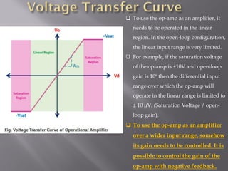
❑ To usethe op-amp as an amplifier, it
needs to be operated in the linear
region. In the open-loop configuration,
the linear input range is very limited.
❑ For example, if the saturation voltage
of the op-amp is ±10V and open-loop
gain is 106 then the differential input
range over which the op-amp will
operate in the linear range is limited to
± 10 μV. (Saturation Voltage / open-
loop gain).
❑ To use the op-amp as an amplifier
over a wider input range, somehow
its gain needs to be controlled. It is
possible to control the gain of the
op-amp with negative feedback.
10.
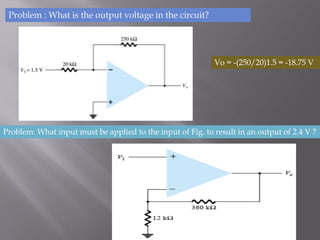
Problem : Whatis the output voltage in the circuit?
Vo = -(250/20)1.5 = -18.75 V
Problem: What input must be applied to the input of Fig. to result in an output of 2.4 V ?
11.
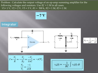
Problem : Calculatethe output voltage of an op-amp summing amplifier for the
following voltages and resistors. Use Rf = 1 M in all cases.
V1= 1 V, V2 = 2 V, V3 = 3 V, R1 = 500 k, R2 = 1 M, R3 = 1 M.
Integrator
12.
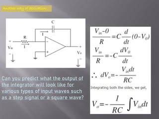
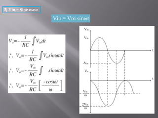
Another way ofderivation:
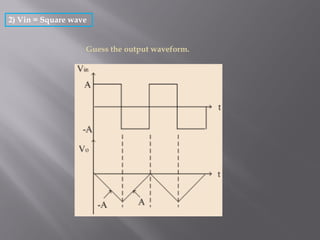
Can you predict what the output of
the integrator will look like for
various types of input waves such
as a step signal or a square wave?
13.
1) Vin =Step signal (a fixed voltage)
Vin (t) = A for t > 0
Let, RC = 1
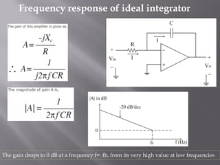
Frequency response ofideal integrator
The gain drops to 0 dB at a frequency f= fb, from its very high value at low frequencies
17.
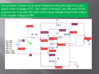
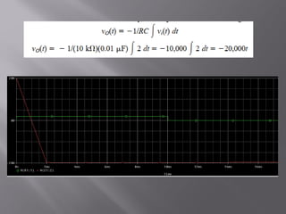
Lab problem: Designan op-amp integrator where the input is a step
signal with a voltage of 2V. The values of R and C are 10k and 0.01uF
respectively. Calculate the time of the ramp voltage drop in the output
if the supply voltage is 20V.
19.
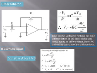
Differentiator
Thus output voltageis nothing but time
differentiation of the input signal and
hence acting as differentiator. Here 'RC'
is the time constant of the differentiator.
1) Vin = Step signal
Vin (t) = A for t > 0
20.
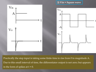
Practically the stepinput is taking some finite time to rise from 0 to magnitude A.
Due to this small interval of time, the differentiator output is not zero; but appears
in the form of spikes at t = 0.
2) Vin = Square wave
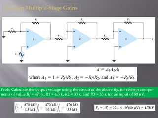
Op-amp Multiple-Stage Gains
Prob:Calculate the output voltage using the circuit of the above fig. for resistor compo-
nents of value Rf = 470 k, R1 = 4.3 k, R2 = 33 k, and R3 = 33 k for an input of 80 uV.