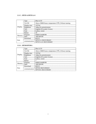
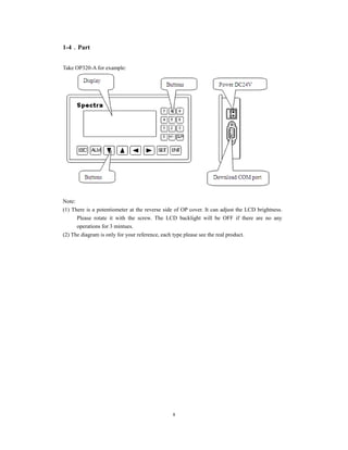
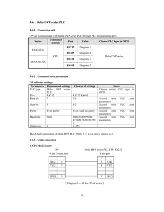
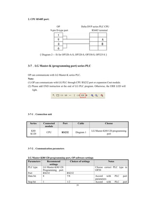
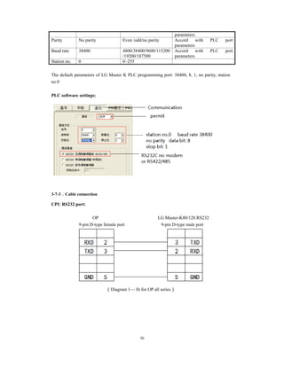
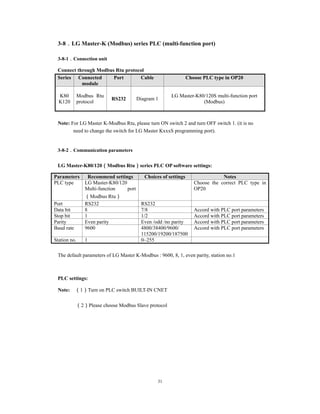
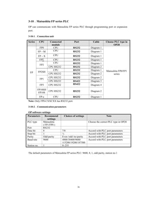
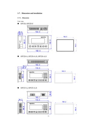
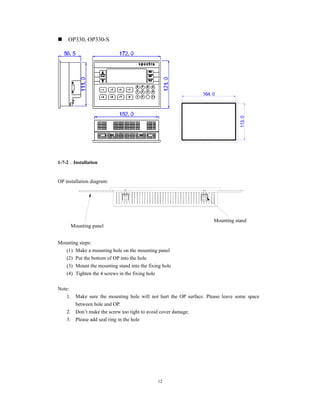
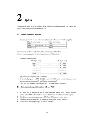
OP operate panel
User manual
Spectra Technologies Co.Ltd.
Basic instructions
Thanks for buying OP series operate panel.
This manual will introduce the hardware features and wiring of OP.
Please read the manual carefully before wiring.
For OP software, please refer to OP software manual.
Please pass the manual to the final user.
User notes
Only the operator who has electrical knowledge can use the OP. Please consult us if there
is anything unclear.
The examples in the manual are only for reference, we are not sure they can work.
Please confirm the product is accord with related specifications when use with other
products.
Please confirm the product is accord with safety requirements when using. Please set the
safety function for the machine.
Responsibility
We cannot ensure the manual contents are accord with the product totally though we have
checked the manual carefully.
We are glad to accept customers’ advice. We will often check the manual contents and
modify them in the next version.
Please note that we will not inform customers if the manual has been modified.
Contact us
Telephone: 866-3-7360023
Address: 2f,No.434,Wen Chung Road,Taoyuan city, Taoyuan Hsien 330,Taiwan
Spectra Technologies Co.Ltd.
All rights reserved
Without written permission, copy, transfer or use the contents in the manual are forbidden.
July, 2011
1
Catalog
1 HARDWARE ...............................................................................................................................5 
1-1.INTRODUCTION................................................................................................................................................... 5 
1-2.GENERAL SPECIFICATIONS.................................................................................................................................. 5 
1-3.FUNCTION SPECIFICATIONS................................................................................................................................. 6 
1-3-1.OP320/OP320-S ...........................................................................................................6 
1-3-2.OP320-A/OP320-A-N/OP320-A-S ..............................................................................6 
1-3-3.OP325-A/OP325-A-S...................................................................................................7 
1-3-4.OP330/OP330-S ...........................................................................................................7 
1-4.PART ................................................................................................................................................................... 8 
1-5.BUTTON FUNCTION............................................................................................................................................. 9 
1-6.PORT AND DOWNLOAD CONNECTION................................................................................................................ 10 
1-6-1.Port .............................................................................................................................10 
1-6-2.Download connection.................................................................................................10 
1-7.DIMENSION AND INSTALLATION ....................................................................................................................... 11 
1-7-1.Dimension ..................................................................................................................11 
1-7-2.Installation..................................................................................................................12 
2 Q&A ............................................................................................................................................13 
2-1.CANNOT DOWNLOAD PROGRAM....................................................................................................................... 13 
2-2.COMMUNICATION PROBLEM ABOUT OPAND PLC............................................................................................ 13 
2-3.PROGRAM SECURITY ........................................................................................................................................ 14 
2-4.INTERACTIVE CONTROL.................................................................................................................................... 14 
2
2-5.SET DATA IN SEQUENCE .................................................................................................................................... 15 
2-6.OTHERS ............................................................................................................................................................ 15 
3 PLC CONNECTION .................................................................................................................16 
3-1.SPECTRA XC SERIES PLC................................................................................................................................. 16 
3-1-1.Connection unit ..........................................................................................................16 
3-1-2.Communication parameter .........................................................................................16 
3-1-3.Cable connection ........................................................................................................17 
3-2.MITSUBISHI FX SERIES PLC............................................................................................................................. 19 
3-2-1.Connection unit ..........................................................................................................19 
3-2-2.Communication parameters........................................................................................19 
3-2-3.Cable connection ........................................................................................................20 
3-3.SIEMENS S7-200 SERIES PLC........................................................................................................................... 21 
3-3-1.Connection unit ..........................................................................................................21 
3-3-2.Communication parameters........................................................................................21 
3-3-3.Cable connection ........................................................................................................22 
3-4.OMRON C SERIES PLC...................................................................................................................................... 22 
3-4-1.Connection unit ..........................................................................................................22 
3-4-2.Communication parameters........................................................................................23 
3-4-3.Cable connection ........................................................................................................24 
3-5.KOYO S SERIES PLC......................................................................................................................................... 25 
3-5-1.Connection unit ..........................................................................................................25 
3-5-2.Communication parameters........................................................................................26 
3
3-5-3.Cable connection ........................................................................................................27 
3-6.DELTA DVP SERIES PLC................................................................................................................................... 28 
3-6-1.Connection unit ..........................................................................................................28 
3-6-2.Communication parameters........................................................................................28 
3-6-3.Cable connection ........................................................................................................28 
3-7.LG MASTER-K (PROGRAMMING PORT) SERIES PLC......................................................................................... 29 
3-7-1.Connection unit ..........................................................................................................29 
3-7-2.Communication parameters........................................................................................29 
3-7-3.Cable connection ........................................................................................................30 
3-8.LG MASTER-K (MODBUS) SERIES PLC (MULTI-FUNCTION PORT).................................................................... 31 
3-8-1.Connection unit ..........................................................................................................31 
3-8-2.Communication parameters........................................................................................31 
3-8-3.Cable connection ........................................................................................................32 
3-9.LG MASTER-K (CNET) SERIES PLC (MULTI-FUNCTION PORT) ......................................................................... 33 
3-9-1.Connection unit ..........................................................................................................33 
3-9-2.Communication parameters........................................................................................33 
3-9-3.Cable connection ........................................................................................................35 
3-10.MATSUSHITA FP SERIES PLC.......................................................................................................................... 36 
3-10-1.Connection unit ........................................................................................................36 
3-10-2.Communication parameters......................................................................................36 
3-10-3.Cable connection ......................................................................................................37 
3-11.SCHNEIDER NEZASERIES PLC...................................................................................................................... 39 
4
3-11-1.Connection unit.........................................................................................................39 
3-11-2.Communication parameters......................................................................................39 
3-11-3.Cable connection ......................................................................................................41 
3-12.FATEK FB SERIES PLC.................................................................................................................................... 41 
3-12-1.Connection unit ........................................................................................................41 
3-12-2.Communication parameters......................................................................................42 
3-12-3.Cable connection ......................................................................................................42 
3-13.VIGOR VB SERIES PLC................................................................................................................................... 44 
3-13-1.Connection unit ........................................................................................................44 
3-13-2.Communication parameters......................................................................................44 
3-13-3.Cable connection ......................................................................................................45 
3-14.EMERSON EC20 SERIES PLC.......................................................................................................................... 46 
3-14-1.Connected unit..........................................................................................................46 
3-14-2.Communication parameters......................................................................................46 
3-14-3.Cable connection ......................................................................................................46 
3-15.IDEC MICRO SMART SERIES PLC .................................................................................................................. 47 
3-16.KEYENCE KV SERIES PLC.............................................................................................................................. 48 
3-17.SAIA-BURGESS PCD SERIES PLC ................................................................................................................. 48 
5
1 Hardware
1-1.Introduction
OP series operate panel can control the PLC through buttons, texts, lamps.
Characteristics:
Edit the program in OP20 software, download program via PC serial port
Can communicate with various PLCs. Such as Mitsubishi FX series, Omron C series,
Siemens S7 series, Koyo SG series and so on
Password function
Built-in RTC
OP can display dynamic text
Alarm function
All the buttons can be defined as multi-function
STN LCD with backlight
Protection level is up to IP65
Support bmp picture displaying
1-2.General specifications
1. Electrical spec
Input voltage DC24V
Input voltage range DC20V-DC28V
Power < 4W(TYPE2.0W)
Power-off permission < 20ms
Voltage endurance AC1000V-10MA 1minute (signal and ground)
Insulated resistance DC500V- about 10MΩ (signal and ground)
2.Environment
Operate temperature 0~50℃, no condensation
Storage temperature –20~60℃
Humidity 20~85% (no condensation)
Vibration endurance 10~25Hz(X, Y, Z direction 30 minutes 2G)
Noise immunity Voltage noise: 1000Vp-p, pulse width is 1
Air No corrosive gas
Protection IP65 for front cover
Cooling method Natural cooling
6
1-3.Function specifications
OP series:
Type Button LCD Backlight Port Dimension (mm)
Mounting
dimension (mm)
OP320
7
3.7”
STN
LCD
RS232/RS422
162.0×102.0×38.0 156.5×94.0
OP320-S RS232/RS485
OP320-A
20
RS232/RS422
172.0×94.0×30.0 163.0×85.0OP320-A-N RS232
OP320-A-S RS232/RS485
OP325-A RS232/RS422
172.0×94.0×38.3 164.2×86.8
OP325-A-S RS232/RS485
OP330
26
RS232/RS422
172.0×121.0×56.5 164.0×113.0
OP330-S RS232/RS485
1-3-1.OP320/OP320-S
Display
Type Blue LCD
Use life Above 20000 hours, temperature 25℃, 24-hour running
Display area 192*64
Brightness Adjust by potentiometer
Text English (24 words×4 rows)
Font Lattice, vector
Button 7
Memory
Program 64KB FalshROM
Data 1KB SRAM
Port
Download RS232
communication
OP320: RS232/RS422
OP320-S: RS232/RS485
1-3-2.OP320-A/OP320-A-N/OP320-A-S
Display
Type Blue LCD
Use life Above 20000 hours, temperature 25℃, 24-hour running
Display area 192*64
Brightness Adjust by potentiometer
Text English (24 words×4 rows)
Font Lattice, vector
Button 20
Memory
Program 64KB FalshROM
Data 1KB SRAM
Port
Download RS232
communication
OP320-A: RS232/RS422
OP320-A-N: RS232
OP320-S: RS232/RS485
7
1-3-3.OP325-A/OP325-A-S
Display
Type Blue LCD
Use life Above 20000 hours, temperature 25℃, 24-hour running
Display area 192*64
Brightness Adjust by potentiometer
Text English (24 words×4 rows)
Font Lattice, vector
Button 20
Memory
Program 64KB FalshROM
Data 1KB SRAM
Port
Download RS232
communication
OP325-A: RS232/RS422
OP325-A-S: RS232/RS485
1-3-4.OP330/OP330-S
Display
Type Blue LCD
Use life Above 20000 hours, temperature 25℃, 24-hour running
Display area 192*64
Brightness Adjust by potentiometer
Text English (24 words×4 rows)
Font Lattice, vector
Button 7
Memory
Program 64KB FalshROM
Data 1KB SRAM
Port
Download RS232
communication
OP330: RS232/RS422
OP330-S: RS232/RS485
8
1-4.Part
Take OP320-A for example:
Note:
(1) There is a potentiometer at the reverse side of OP cover. It can adjust the LCD brightness.
Please rotate it with the screw. The LCD backlight will be OFF if there are no any
operations for 3 mintues.
(2) The diagram is only for your reference, each type please see the real product.
9
1-5.Button function
The buttons on the OP panel can be defined as many functions. They can instead of the buttons
on the control machine which has long using life and better touch feeling.
Besides, these buttons can be defined to special function such as set on /off bit, screen jump. If
no need special functions, the buttons will execute basic functions: set the value of register, reset
original screen, page up/down.
Buttons functions:
Button Basic function
Return to the original screen (default is screen no.1). The main menu or frequenct-used
screen can be set to original screenESC
Left shift data bit when changing the register
Right shift data bit when changing the register
Page down, the default value = current page -1.
Minus one for the data being changed, the range is 0 -> 9 -> 0
Page up, the default value = current page +1.
Plus one for the data being changed, the range is 9 -> 0 -> 9
SET
Press this button to change the register value, the changed bit is shining. If there is no
register in the program, this button executes do-nothing operation.
Press this button before pressing ENT to cancel the current modification and continue to
change the next register.
ENT Confirm the modification and continue the next one
ALM
After setting alarm list function, press this button to enter alarm screen
Used as function button
CLR
Clear the register value
Used as function button
+/ -
Set the negative or positive of value
Used as function button
n
Numeric button (range: 0~9)
Used as function button
Fn Overall function button or normal function button
10
1-6.Port and download connection
1-6-1.Port
OP series has a DB9 port. It can download program and communicate with other devices.
OP320, OP320-A,
OP325-A, OP330
OP320-A-N
OP320-S, OP320-A-S,
OP325-A-S, OP330-S
Pin Name
1 TD+
2 RXD
3 TXD
4
5 GND
6 TD-
7
8 RD-
9 RD+
Pin Name
2 RXD
3 TXD
4
5 GND
6
7
8
9
Pin Name
1 TD+
2 RXD
3 TXD
4
5 GND
6 TD-
7
8 B
9 A
1-6-2.Download connection
Please use OP cable to connect OP 9-pin port and PC serial port. The cable can be also used to
connect OP and PLC.
OP and PC connection diagram:
OP (9-pin port) PC (9-pin port)
RXD
TXD
GND 5
7
3
2 RXD
TXD
GND
CTS
5
7
3
2
11
1-7.Dimension and installation
1-7-1.Dimension
Unit: mm
OP320, OP320-S
156. 5
94.0
OP320-A, OP320-A-N, OP320-A-S
85.0
163. 0
OP325-A, OP325-A-S
86.8
164. 2
12
OP330, OP330-S
164. 0
113.0
1-7-2.Installation
OP installation diagram:
Mounting steps:
(1) Make a mounting hole on the mounting panel
(2) Put the bottom of OP into the hole
(3) Mount the mounting stand into the fixing hole
(4) Tighten the 4 screws in the fixing hole
Note:
1. Make sure the mounting hole will not hurt the OP surface. Please leave some space
between hole and OP.
2. Don’t make the screw too tight to avoid cover damage.
3. Please add seal ring in the hole
Mounting panel
Mounting stand
13
2 Q&A
OP program is edited in OP20 software; please refer to OP software manual. This chapter will
explain some general questions about using OP.
2-1.Cannot download program
1. The version of hardware and software must be matched. Please see the following table.
Hardware version Software version
V3.6 V3.6
V4.0—V7.0 (not include 7.0) V6.5z
V7.0—V8.0 V8.0n
Hardware version: Please see the label at the reverse side of OP product.
Software version: please see the item Help/about…. in OP20 software.
2. Check the download cable
OP (9-pin port) PC (9-pin port)
RXD
TXD
GND 5
7
3
2 RXD
TXD
GND
CTS
5
7
3
2
3. Try to download program via PC serial port.
4. If download program via USB-RS232 converter, it will be error sometime. Because some
converter doesn’t connect pin7, but OP need to connect pin7.
5. Open the OP20 software, click file/com port… to choose the PC serial port.
2-2.Communication problem about OP and PLC
1. PLC and OP is all powered on, and the cable connection is well; the PLC device choice is
correct in the OP20 software. Please refer to chapter 3 for the cable connection diagram.
2. Check the communication parameters of PLC and OP, they must be the same.
3. Check the station no. especially the station no. of alarm list, register and relay.
4. Don’t choose analog input/output in Tool/Set OP series...
14
5. Contact us if they still cannot communicate.
2-3.Program security
OP program cannot be uploaded for security reason.
2-4.Interactive control
Please choose “auto change display Screen” and set register address in Tool/Set OP series…
Set the register to n, OP will jump to screen No.n when power on. Then the register value will be
cleared.
15
2-5.Set data in sequence
If there are many values need to set in one screen, please click each of them in sequence before
downloading. Then you can set these values in sequence.
2-6.Others
1. When choosing Modbus or free format protocol, OP20 will have register 4x, 3x, 1x, 0x.
1x and 3x mean read only.
0x and 4x mean read and write.
2. OP320/OP320-A/OP325/OP330 cannot support RS485.
16
3 PLC connection
This chapter will introduce the connection method of OP and PLC.
The communication steps of PLC and OP:
1. Choose the PLC type communicating with OP. Check if the communication parameters of
OP and PLC are the same. The station no. of each part in the OP program should be same to
PLC.
2. Please disconnect the OP cable with PC after finish the downloading.
3. Connect OP and PLC with PLC cable, power on them, OP starts to work.
3-1.Spectra XC series PLC
3-1-1.Connection unit
Series CPU
Connected
module
Port Cable Choose PLC type in OP20
XC
XC1
XC2
XC3
XC5
XCM
XCC
CPU
RS232 Diagram 1
Spectra XC series
RS485 Diagram 2
3-1-2.Communication parameter
OP software default settings:
Parameter Recommend
Settings
Choices of settings Note
PLC model XC series FC/XC series Choose correct PLC model
communicating with OP
Port RS232 RS232/RS485
Data bit 8 7/8 Accord with PLC port settings
Stop bit 1 1/2 Accord with PLC port settings
Parity Even parity Even /odd/no parity Accord with PLC port settings
Baud rate 19200 4800/38400/9600/115200
/19200/187500
Accord with PLC port settings
Station no. 1 0~255
Default communication parameters of Spectra XC series PLC: 19200, 8, 1, even parity, station
no.1.
17
PLC software settings:
3-1-3.Cable connection
1. Direct connect to XC series PLC CPU (RS232 port)
XC series PLC CPU
OP RS232 port (PORT1 or PORT2)
9-pin D-type female port 8-pin round port
(Diagram 1: fit for OP all series)
PLC port:
18
2. Direct connect to XC series PLC CPU (RS485 port)
OP Spectra XC series PLC CPU
9-pin D-type female port RS485 terminal (PORT2)
(Diagram 2— fit for OP320-S, OP320-A-S, OP325-S, OP330-S)
3. Connect PLC via XC-COM-BD (RS232)
OP XC-COM-BD
9-pin D-type female port RS232 8-pin port
(Diagram 3— fit for OP all series)
4. Connect PLC via XC-COM-BD ( RS485)
OP XC-COM-BD
9-pin d-type female port RS485 8-pin port
(Diagram 4— fit for OP320-S, OP320-A-S, OP325-S, OP330-S)
19
3-2.Mitsubishi FX series PLC
3-2-1.Connection unit
Series CPU Connected
module
Port Cable Choose PLC type in OP20
FX
FX0N
FX1N
FX2N
FX1S
FX3U
CPU RS422
Diagram
1
Mitsubishi FX series PLC
FX3G
FX0
FX1
CPU RS422
Diagram
1
Mitsubishi FX series PLC
FX2 CPU RS422
Diagram
2
Mitsubishi FX series PLC
3-2-2.Communication parameters
OP default settings
Series Recommend
settings
Choices of settings Note
PLC type FX series
Choose correct PLC model
communicating with OP
Data bit 7 7/8 Accord with PLC port settings
Stop bit 1 1/2 Accord with PLC port settings
Parity Even parity Even /odd/no parity Accord with PLC port settings
Baud rate 9600
4800/9600/19200/38400/560
00
/57600/115200/187500
Accord with PLC port settings
Station no. 0 0~255
The default parameters of Mitsubishi FX series PLC: 9600, 7, 1, even parity, station no. 0
20
PLC software settings:
3-2-3.Cable connection
1. FX1N/2N/3U/3G/1S series PLC (RS422)
MITSUBISHI PLC
OP FX series CPU RS422
9-pin D-type female port 8-pin round port
(Diagram 1— fit for OP320, OP320-A, OP325, OP330)
21
2. FX2 series PLC
MITSUBISHI PLC
OP FX2 series CPU RS422
9-pin D-type female port 25-pin D-type male port
(Diagram 2— fit for OP320, OP320-A, OP325, OP330)
3-3.Siemens S7-200 series PLC
3-3-1.Connection unit
OP series can communicate with S7-200 series PLC (PPI protocol) via programming port or
expansion port.
Series CPU Connected
module
Port Cable Choose PLC type in OP20
S7-200
CPU212
CPU221
CPU222
CPU224
CPU226
CPU RS485 Diagram 1 Siemens S7-200 series PLC
3-3-2.Communication parameters
OP software settings
Parameters Recommend
settings
Choices of settings Note
PLC type S7-200 Choose correct PLC type when
communicating with OP
Port RS485 RS485
Data bit 8 7/8 Accord with PLC port
parameters
Stop bit 1 1/2 Accord with PLC port
parameters
Parity
Even parity Even /odd /no parity Accord with PLC port
parameters
Baud rate 9600 4800/38400/9600/115200
/19200/187500
Accord with PLC port
parameters
Station no. 2 Must use recommend settings
The default parameters of Siemens S7-200 series PLC: 9600, 8, 1, even parity, station no.2
22
PLC software settings:
S7-200 communication notes:
1. Siemens PLC register has VB (8-bit), VW(16-bit), VD(32-bit).
2. The register address is overlapped. VW address should be the times of 2; VD address should
be the times of 4.
3-3-3.Cable connection
OP S7-200 series PLC RS485
9-pin D-type female port 9-pin D-type male port
(Diagram 1— fit for OP320-A-S, OP320-S, OP330-S, OP325-S)
3-4.Omron C series PLC
OP can communicate with Omron SYSMAC series CJ/CS/CP/CPM/CQM PLC.
Note:
1. CPM1A, CQM1-CPU series CPU don’t have RS232 port, please configure OMRON CIF01
(RS232)adapter with them. In actual application, please use communication module
C500-LK203, C120-LK201-V1, C500-LK201-V1 to finish the RS232 communication.
2. Please choose Hotlinks protocol in PLC software.
3. PLC start choice please set to MONITOR RUN.
3-4-1.Connection unit
Series CPU Connected module Port Cable Choose PLC
type in OP20
CP CP1E-30N
CP1H
CP1L
CPU RS232
Port
RS232
Diagram
1
Omron
CP/CJ/CS
series
Module CP1W-CIF11 RS485
Diagram
2
Module CP1W-CIF11 RS422
Diagram
3
CJ CJ1G-CPU44
CJ1G-CPU45
CPU RS232
Port
RS232
Diagram
1
CS1 CS1H-CPU63/
64/65/66/67
CS1G-CPU42/
43/44/45
CS1G-CPU42H
CS1G-CPU43H
CPU RS232
port
RS232
Diagram
1
23
CS1G-CPU44H
CS1G-CPU45H
CS1H-CPU63H
CS1H-CPU64H
CS1H-CPU65H
CS1H-CPU66H
CS1H-CPU67H
C200 C200HE CPU RS232
Port
RS232
Diagram
1
CPM CPM2A
CPM2AE
CPM2AH-40CDR-A CPU RS232
Port
RS232
Diagram
1
Omron
CPM/CQM
series
CQM1 CQM1-CPU42
CPM1A OMRON
CIF01(RS232)
Communication
adapter
RS232
Diagram
1
CQM1-CPU11
C1000HF C500-LK203
(Communication
module)
Omron
CP/CJ/CS
series
C2000
C120-LK201-V1
(Communication
module)
C500-LK201-V1
(Communication
module)
C500-LK203
(Communication
module)
3-4-2.Communication parameters
(1) Omron CP/CJ/CS series
OP software settings:
Parameters Recommend settings Choices of settings Note
PLC type
Omron CP/CJ/CS
series
Omron CP/CJ/CS series
Omron CPM/CQM series
Please choose correct PLC type
in OP20 software
Port RS232 RS232
Data bit 7 7/8
Accord with PLC port
parameters
Stop bit 2 1/2
Accord with PLC port
parameters
Parity Even parity Even /odd/no parity
Accord with PLC port
parameters
Baud rate 9600
4800/38400/9600/115200
/19200/187500
Accord with PLC port
parameters
Station no. 0 0~255
The default parameters of Omron CP/CJ/CS series: 9600, 7, 2, even parity, station no.0
24
(2) Omron CPM/CQM series
OP software settings:
Parameters Recommend
settings
Choices of settings Notes
PLC type Omron
CPM/CQM series
Omron CP/CJ/CS series
Omron CPM/CQM series
Choose correct PLC type in
OP20
Port RS232 RS232
Data bit 7 7/8 Accord with PLC port
parameters
Stop bit 2 1/2 Accord with PLC port
parameters
Parity Even parity Even /odd/no parity Accord with PLC port
parameters
Baud rate 9600 4800/38400/9600/115200
/19200/187500
Accord with PLC port
parameters
Station no. 0 0~255
The default parameters of Omron CPM/CQM series PLC: 9600, 7, 2, even parity, station no.0
3-4-3.Cable connection
1. CPU RS232:
OP Omron CPM/CQM series CPU
9-pin D-type female port 9-pin D-type male port
(Diagram 1— fit for OP all series)
2. Module CP1W-CIF11 RS485:
OP Module CP1W-CIF11
9-pin D-type female port RS485 terminal
(Diagram 2— fit for OP320-A-S, OP320-S, OP330-S, OP325-S)
25
Note: For Omron module CP1W-CIF11, please turn OFF SW1; turn ON SW2, 3, 6; turn
ON or OFF SW4.
3. Module CP1W-CIF11 RS422:
OP Module CP1W-CIF11
9-pin D-type female port RS422 terminal
(Diagram 3— fit for: OP320, OP320-A, OP325, OP330)
Note: For Omron485 module CP1W-CIF11 RS422 connection, please turn OFF SW1~6.
3-5.Koyo S series PLC
3-5-1.Connection unit
OP can communicate with Koyo KOSTA-S series, Koyo Direct-Logic series PLC.
1. Koyo Kostac S series, SHSMSN PLC (direct connect to CPU)
Series CPU Connected
module
Port Cable Choose PLC type in
OP20
SH
SH-48RS
CPU RS232 Diagram 2
Koyo S series
SM
SM24-T
SN
SU-6
CPU
RS232 Diagram 1
SU-6B
RS232 Diagram 1
RS422 Diagram 3
Note: Koyo SH-48RS doesn’t have Run, Stop switch, but only one port (modular plug)
26
2. Koyo Direct Logic series DL05, DL250 PLC (direct connect to CPU)
Series CPU Connected
module
Port Cable Choose correct PLC in
OP20
Direct
Logic
DL05
DL105
DL230
DL240
DL250
DL350
DL450
CPU RJ-11 port RS232 Diagram 2
Koyo S series
DL250
CPU com port RS422 Diagram 3
DL430
DL440
DL450
DL350
CPU com port
RS232 Diagram 2
Note: DL250 CPU PORT2 has RS232 and RS422, please choose the correct communication
cable.
3-5-2.Communication parameters
OP software settings:
Parameters Recommend
settings
Choices of settings Notes
PLC type
Koyo S series
PLC
Please choose correct PLC type in
OP20
Port RS232 RS232/RS422
Data bit 8 7/8 Accord with PLC port parameters
Stop bit 1 1/2 Accord with PLC port parameters
Parity Odd parity Even /odd /no parity Accord with PLC port parameters
Baud rate 9600
4800/38400/9600/115200
/19200/187500
Accord with PLC port parameters
Station no. 0 0~255
The default parameters of Koyo S series PLC: 9600, 8, 1, odd parity, station no.0
PLC software settings:
1. Choose K protocol, station no.1 in the software.
2. Koyo K procotol doesn’t have station no. problem, the communication parameters
cannot be changed. It is no need to change the station no. of OP. (OP20 default station
no. is 0, it is not need to be changed).
3. The register address starts from R2000 in OP20.
27
3-5-3.Cable connection
1. CPU or communication unit 25-pin RS232 port
SG-8, SU-5, SU-6, SU-6B
OP 350/430/440/450 RS232 port
9-pin port 25-pin port
(Diagram 1— fit for OP all series)
2. CPU 6-pin RJ-11 RS232 port
OP SZ-4, DL05/105/230/250 RS232
9-pin D-type port 6-pin RJ-11 port
(Diagram 2— fit for OP all series)
3. RS422 connection:
SU-6B, SG-8(G01-DM),
OP SR-21/SR-22(E-02DM-R1), DL250
9-pin D-type port RS422 15-pin SVGA port
(Diagram 3— fit for OP320, OP320-A, OP325, OP330)
123456
28
3-6.Delta DVP series PLC
3-6-1.Connection unit
OP can communicate with Delta DVP series PLC through PLC programming port.
Series
Connected
module
Port Cable Choose PLC type in OP20
ES/EH/EX
CPU
RS232 Diagram 1
Delta DVP series
RS485 Diagram 2
SS/SA/SC/SX
RS232 Diagram 1
RS485 Diagram 2
3-6-2.Communication parameters
OP software settings:
Parameters Recommend settings Choices of settings Notes
PLC type Delta DVP series
PLC
Choose correct PLC type in
OP20
Port RS232 RS232/RS485
Data bit 7 7/8 Accord with PLC port
parameters
Stop bit 1 1/2 Accord with PLC port
parameters
Parity Even parity Even /odd /no parity Accord with PLC port
parameters
Baud rate 9600 4800/38400/9600/
115200/19200/18750
0
Accord with PLC port
parameters
Station no. 1 0~255
The default parameters of Delta DVP PLC: 9600, 7, 1, even parity, station no.1
3-6-3.Cable connection
1. CPU RS232 port:
OP Delta DVP series PLC CPU RS232
9-pin D-type port 8-pin port
(Diagram 1— fit for OP all series)
29
2. CPU RS485 port:
OP Delta DVP series PLC CPU
9-pin D-type port RS485 terminal
(Diagram 2— fit for OP320-A-S, OP320-S, OP330-S, OP325-S)
3-7.LG Master-K (programming port) series PLC
OP can communicate with LG Master-K series PLC.
Note:
(1) OP can communicate with LG PLC through CPU RS232 port or expansion Cnet module.
(2) Please add END instruction at the end of LG PLC program. Otherwise, the ERR LED will
light.
3-7-1.Connection unit
Series Connected
module
Port Cable Choose
K80
K120
CPU RS232 Diagram 1
LG Master-K80/120-programming
port
3-7-2.Communication parameters
LG Master-K80/120-programming port, OP software settings
Parameters Recommend
settings
Choices of settings Notes
PLC type LG Master-K80/120
Programming port
Choose correct PLC type in
OP20
Port RS232 RS232
Data bit 8 7/8 Accord with PLC port
parameters
Stop bit 1 1/2 Accord with PLC port
30
parameters
Parity No parity Even /odd/no parity Accord with PLC port
parameters
Baud rate 38400 4800/38400/9600/115200
/19200/187500
Accord with PLC port
parameters
Station no. 0 0~255
The default parameters of LG Master K PLC programming port: 38400, 8, 1, no parity, station
no.0
PLC software settings:
3-7-3.Cable connection
CPU RS232 port:
OP LG Master-K80/120 RS232
9-pin D-type female port 9-pin D-type male port
(Diagram 1— fit for OP all series)
31
3-8.LG Master-K (Modbus) series PLC (multi-function port)
3-8-1.Connection unit
Connect through Modbus Rtu protocol
Series Connected
module
Port Cable Choose PLC type in OP20
K80
K120
Modbus Rtu
protocol
RS232 Diagram 1
LG Master-K80/120S multi-function port
(Modbus)
Note: For LG Master K-Modbus Rtu, please turn ON switch 2 and turn OFF switch 1. (it is no
need to change the switch for LG Master KxxxS programming port).
3-8-2.Communication parameters
LG Master-K80/120(Modbus Rtu)series PLC OP software settings:
Parameters Recommend settings Choices of settings Notes
PLC type LG Master-K80/120
Multi-function port
(Modbus Rtu)
Choose the correct PLC type in
OP20
Port RS232 RS232
Data bit 8 7/8 Accord with PLC port parameters
Stop bit 1 1/2 Accord with PLC port parameters
Parity Even parity Even /odd /no parity Accord with PLC port parameters
Baud rate 9600 4800/38400/9600/
115200/19200/187500
Accord with PLC port parameters
Station no. 1 0~255
The default parameters of LG Master K-Modbus : 9600, 8, 1, even parity, station no.1
PLC settings:
Note: (1)Turn on PLC switch BUILT-IN CNET
(2)Please choose Modbus Slave protocol
32
RS232 communication
3-8-3.Cable connection
1. LG Modbus Rtu RS232:
OP Controller
9-pin D-type female port 9-pin D-type male port
(fit for : OP all series)
33
2. LG Modbus Rtu RS485:
OP Controller
9-pin D-type female port RS485 terminal
(fit for : OP320-A-S, OP320-S, OP330-S, OP325-S)
3-9.LG Master-K (Cnet) series PLC (multi-function port)
3-9-1.Connection unit
Expansion Cnet module:
Series Connected
module
Port Cable Choose PLC type in OP20
K80
K120
Cnet
RS232 Diagram
1 LG Master-K80/120S multi-function
port (Cnet)RS485 Diagram
2
Note:
(1)For LG Master K-cnet, please turn ON switch 2 and turn off switch 1. (It is no need to
change the switch of LG Master KxxxS)
(2)LG Master KxxxS programming port cannot support RS485. Cnet can support RS485.
3-9-2.Communication parameters
LGMaster-K80/120(Cnet)PLC OP software settings
Parameters Recommend
settings
Choices of settings Notes
PLC type LG Master-K80/120
Multi-function port
(Cnet)
Choose the correct PLC type in
OP20
Port RS232 RS232
Data bit 8 7/8 Accord with PLC port parameters
Stop bit 1 1/2 Accord with PLC port parameters
Parity No parity Even /odd/no parity Accord with PLC port parameters
Baud rate 19200 4800/38400/9600/1152
00
/19200/187500
Accord with PLC port parameters
Station no. 1 0~255
The default parameters of LG Master K-cnet: 19200, 8, 1, no parity, station no.
34
PLC settings
Notes: (1)Turn ON switch BUILT-IN CNET of PLC.
(2)Please choose special slave procotol. (Cannot choose Modbus slave).
RS232
RS485
35
3-9-3.Cable connection
1. CPU(or expansion Cnet module)
OP Cnet communication module
9-pin D-type female port 9-pin D-type male port
(Diagram 1— fit for OP all series)
Note: (1)Turn ON switch BUILT-IN CNET of PLC.
(2)Choose CNet port when making new PLC program.
2. RS485 connection:
OP Cnet communication module
9-pin D-type port RS485 terminal
(Diagram 2— fit for OP320-A-S, OP320-S, OP330-S, OP325-S)
36
3-10.Matsushita FP series PLC
OP can communicate with Matsushita FP series PLC through programming port or expansion
port.
3-10-1.Connection unit
Series CPU Connected
module
Port Cable Choose PLC type in
OP20
FP
FP0 CPU RS232 Diagram 1
Matsushita FP0/FP1
series
FP-M CPU RS232 Diagram 1
FP-X CPU RS232 Diagram 1
FP∑ CPU RS232 Diagram 1
FP2
CPU RS232 Diagram 1
CPU RS232 RS232 Diagram 2
FP2SH
CPU RS232 Diagram 1
CPU RS232 RS232 Diagram 2
FP1
CPU RS232 RS232 Diagram 2
CPU RS232 RS422 Diagram 3
FP3 CPU RS232 RS422 Diagram 4
FP10SH
FP10S
CPU RS232 RS232 Diagram 2
FP-e CPU RS232 Diagram 1
Note: Only FP0-CXXCXX has RS232 port.
3-10-2.Communication parameters
OP software settings
Parameters Recommend
settings
Choices of settings Note
PLC type Matsushita
( FP1/FP0 )
Choose the correct PLC type in OP20
Port RS232
Data bit 8 7/8 Accord with PLC port parameters
Stop bit 1 ½ Accord with PLC port parameters
Parity Odd parity Even /odd /no parity Accord with PLC port parameters
Baud rate 9600 4800/38400/9600/
115200/19200/187500
Accord with PLC port parameters
Station no. 1 0~255
The default parameters of Matsushita FP series PLC: 9600, 8, 1, odd parity, station no.1
37
PLC settings
Note:
(1) Please set the PLC register like this in OP software:
PLC OP
R45
(2)Make sure the PLC switch is turn to PPOG
(3)The PLC must RUN when communicating with OP.
(4)Do not choose general communication mode when setting the PLC parameters, otherwise,
the communication will be error.
(5)FP series PLC station no. is 1, but FP3 must be no.0.
3-10-3.Cable connection
1. CPU RS232 port:
OP PLC RS232
9-pin D-type female port 5-pin male port
(Diagram 1— fit for OP all series)
38
2. CPU RS232:
OP PLC RS232
9-pin D-type female port 9-pin D-type male port
(Diagram 2— fit for OP all series)
3. CPU RS422:
Matsushita mewnet-FP series
OP FP1 CPU RS422
9-pin D-type female port 8-pin male port
(Diagram 3— fit for OP320, OP320-A, OP325, OP330)
4. CPU 15-pin port:
OP PLC RS422
9-pin D-type female port 15-pin D-type male port
(Diagram 4— fit for OP320, OP320-A, OP325, OP330)
39
3-11.Schneider NEZA series PLC
OP can communicate with Schneider NEZA PLC through programming port. (Modbus protocol)
3-11-1.Connection unit
Series CPU Connected
module
Port Cable Choose PLC type in OP20
Micro TSX 37-05
TSX 37-08
TSX 37-10
TSX 37-21/22
CPU RS485 Diagram 1
Schneider
Micro/NEZA/Twido
Series PLC
Twido Twido
CPU
CPU RS485 Diagram 1
M M218/M238
/M258
CPU RS485 Diagram 2
NEZA TSX07
CPU
CPU RS485 Diagram 1
3-11-2.Communication parameters
OP software settings
Parameters Recommend
settings
Choices of settings Notes
PLC type Schneider
Micro/
NEZA/ Twido
series PLC
Choose the correct PLC type in OP20
Port RS485
Data bit 8 7/8 Accord with PLC port parameters
Stop bit 1 ½ Accord with PLC port parameters
Parity Even parity Even /odd /no parity Accord with PLC port parameters
Baud rate 19200 4800/38400/9600
/115200/19200/187500
Accord with PLC port parameters
Station no. 1 0~255
Schneider Micro/NEZA/ Twido series PLC: 19200, 8, 1, even parity, station no.1
40
PLC software settings:
Note: 1. The register of Twido is dynamic managed. Please add a sentence at the end of PLC
program to avoid communication error.
2. To open the bit address range, you have to make a program as below. For example: drive a coil
of %M127, all the addresses before %M127 can do data switching.
41
3-11-3.Cable connection
1. CPU RS485:
Schneider Micro/NEZA/Twido series
OP TSX-37, TSX-07, Twido series CPU
9-pin D-type female port 8-pin male port
(Diagram 1— fit for OP320-A-S, OP320-S, OP330-S, OP325-S)
2. M238 CPU:
OP Schneider Micro series CPU
9-pin D-type female port RJ-45 port
(Diagram 2— fit for OP320-A-S, OP320-S, OP330-S, OP325-S)
3-12.Fatek FB series PLC
OP can communicate with Fatek FB series PLC through programming port or com port.
3-12-1.Connection unit
Series CPU
Connected
module
Port Cable Choose
FBs
FBs-20MN
FBs-32MN
FBs-44MN
CPU
RS232 Diagram 1
Fatek MU/MA series
PLC
RS485 Diagram 2
FB -MC
20MC/28MC
40MC/19MCT
26MCT/36MCT
RS232 Diagram 1
RS485 Diagram 2
FB -MA
20MA
28MA
40MA
FB-DTBR/
DTBR-E module
RS232 Diagram 3
RS232 Diagram 4
RS485 Diagram 5
Note: For MA series CPU, please transform the com port to RS232 or RS485 through FB-DTBR
or FB-DTBR-E module
42
3-12-2.Communication parameters
OP software settings
Parameters Recommend
settings
Choices of settings Notes
PLC type Fatek MU/MA
Series PLC
Choose the correct PLC type in
OP20
Port RS232 RS232/RS485
Data bit 7 7/8 Accord with PLC port parameters
Stop bit 1 1/2 Accord with PLC port parameters
Parity Even parity Even /odd /no parity Accord with PLC port parameters
Baud rate 9600 4800/38400/9600/1152
00
/19200/187500
Accord with PLC port parameters
Station no. 1 0~255
The default parameters of Fatek MU/MA series PLC: 9600, 7, 1, even parity, station no.
3-12-3.Cable connection
1. CPU RS232:
(Diagram 1— fit for OP all series)
CPU port:
20MC, 28MC, 40MC, 19MCT, 26MCT,
OP 36MCT series CPU RS232
9-pin D-type female port 15-pin D-type male port
(fit for OP all series)
43
2. CPU RS485:
20MC, 28MC, 40MC, 19MCT, 26MCT,
OP 36MCT series CPU RS485
9-pin D-type female port 15-pin D-type male port
(Diagram 2— fit for OP320-S, OP320-A-S, OP325-S, OP33-S)
3. FB-DTBR/DTBR-E module RS232:
20MA, 28MA, 40MA series FB-DTBR
OP /DTBR-E module RS232
9-pin D-type female port 15-pin D-type male port
(Diagram 3— fit for OP all series)
4. FB-DTBR/DTBR-E RS232:
20MA, 28MA, 40MA series FB-DTBR
OP /DTBR-E module RS232
9-pin D-type female port 9-pin D-type male port
(Diagram 4 — fit for OP all series)
44
5. FB-DTBR/DTBR-E RS485:
20MA, 28MA, 40MA series FB-DTBR
OP /DTBR-E module RS485
9-pin D-type female port 3-pin terminal
(Diagram 5 — fit for OP320-S, OP320-A-S, OP325-S, OP33-S)
3-13.Vigor VB series PLC
OP can communicate with Vigor VB series PLC (including VB0, VB1,VB2) through CPU
programming port.
3-13-1.Connection unit
Series CPU
Connected
module
Port Cable
Choose PLC type
in OP20
VB
VB0-14M
VB0-20M
VB0-28M
VB0-32M
VB1-14MT-D
VB1-24MT-D
VB1-32MTMT-D
VB2-16M
VB2-32M
CPU RS232 Diagram 1
Vigor VB series
PLCExpansion card
RS232 Diagram 2
RS422 Diagram 3
RS485 Diagram 4
VH VH -14MR CPU RS232 Diagram 1
3-13-2.Communication parameters
OP software settings
Parameters Recommend
settings
Choices of settings Note
PLC type Vigor VB series
PLC
Choose correct PLC type in OP20
Port RS232 RS232/RS485/RS422
Data bit 7 7/8 Accord with PLC port parameters
Stop bit 1 1/2 Accord with PLC port parameters
Parity Even parity Even /odd / no parity Accord with PLC port parameters
Baud rate 19200 4800/38400/9600/
115200/19200/187500
Accord with PLC port parameters
Station no. 0 0~255
The default parameters of Vigor VB series PLC: 19200, 7, 1, even parity, station no.0
45
3-13-3.Cable connection
1. CPU RS232-A USB connector:
OP VIGOR VH PLC
9-pin D-type female port USB-A port
(Diagram 1— fit for OP all series)
2. CPU RS232 expansion card:
VIGOR VB series
OP RS232 expansion card
9-pin D-type female port 9-pin D-type male port
(Diagram 2— fit for OP all series)
3. CPU RS485 expansion card:
(1) RS422 connection
VIGOR VB series
OP RS485 expansion card
9-pin D-type female port 5-wire terminal
(Diagram 3— fit for OP320, OP320-A, OP325, OP330)
(2) RS485 connection
VIGOR VB series
OP RS485 expansion card RS485
9-pin D-type female port 5-wire terminal
(Diagram 4 — fit for OP320-S, OP320-A-S, OP325-S, OP33-S)
46
3-14.Emerson EC20 series PLC
3-14-1.Connected unit
Series CPU
Connected
module
Port Cable Choose PLC type in OP20
EC20 EC20
COM0 RS232 Diagram1
Emerson EC20 series PLC
COM1
RS485 Diagram2
RS232 Diagram3
3-14-2.Communication parameters
OP software settings
Parameters Recommend
settings
Choices of settings Note
PLC type Emerson
EC20 series
PLC
Choose correct PLC type in OP20
Port RS232 RS232/RS485
Data bit 8 7/8 Accord with PLC port parameters
Stop bit 1 ½ Accord with PLC port parameters
Parity Even parity Even / odd / no parity Accord with PLC port parameters
Baud rate 9600 4800/38400/9600/
115200/19200/187500
Accord with PLC port parameters
Station no. 1 0~255
Emerson EC20 series PLC: 9600, 8, 1, even parity, station no.1
3-14-3.Cable connection
1. Emerson EC20 PLC COM0 (RS232):
EMERSON-EC20 series CPU
OP COM0 RS232
9-pin D-type female port 8-pin male port
(Diagram 1— fit for OP all series)
2. Emerson EC20 series PLC COM1 (RS232):
EMERSON-EC20 series CPU
OP COM1 RS232
9-pin D-type female port 5-wire terminal
47
(Diagram 2— fit for OP all series)
3. Emerson EC20 series PLC COM1(RS485):
EMERSON-EC20 series CPU
OP COM1 RS485
9-pin D-type female port 5-wire terminal
(Diagram 3— fit for OP320-S, OP320-A-S, OP325-S, OP33-S)
Note: Emerson EC20 series PLC COM1 has RS232 and RS485. Only one of them can be used at
the same time. Do not connect unused com to avoid interference.
3-15.IDEC Micro Smart series PLC
1. IDEC CPU(Micro3 series)RS485:
Idec PLC Micro3 CPU
OP RS485 programming port
9-pin D-type female port 8-pin round male port
(fit for OP320-A-S, OP320-S, OP330-S, OP325-S)
2. IDEC CPU(Micro3C series)RS232:
Idec PLC Micro3C CPU
OP RS232 programming port
9-pin D-type female port 8-pin round male port
(fit for OP all series)
48
3-16.Keyence KV series PLC
Keyence KV series PLC CPU RS232 port:
Keyence KV-10/16/24/40 series PLC
OP CPU RS232
9-pin D-type female port 6-pin RJ-11 port
(fit for OP all series)
PLC RJ-11 port:
1 2 3 4 5 6
3-17.SAIA-Burgess PCD series PLC
SAIA-Burgess PCD series PLC RS232 port:
SAIA-Burgess PCD series PLC
OP RS232
9-pin D-type female port 9-pin D-Sub port
(fit for OP all series)
Spectra Technologies Co.Ltd.
2f,No.434,Wen ChungRoad,Taoyuan city,
Taoyuan Hsien 330,Taiwan
Tel: 866-3-7360023
www.spectra-tw.com
Email: info@spectra-tw.com

Op manual hardware

  • 1.
    OP operate panel Usermanual Spectra Technologies Co.Ltd.
  • 2.
    Basic instructions Thanks forbuying OP series operate panel. This manual will introduce the hardware features and wiring of OP. Please read the manual carefully before wiring. For OP software, please refer to OP software manual. Please pass the manual to the final user. User notes Only the operator who has electrical knowledge can use the OP. Please consult us if there is anything unclear. The examples in the manual are only for reference, we are not sure they can work. Please confirm the product is accord with related specifications when use with other products. Please confirm the product is accord with safety requirements when using. Please set the safety function for the machine. Responsibility We cannot ensure the manual contents are accord with the product totally though we have checked the manual carefully. We are glad to accept customers’ advice. We will often check the manual contents and modify them in the next version. Please note that we will not inform customers if the manual has been modified. Contact us Telephone: 866-3-7360023 Address: 2f,No.434,Wen Chung Road,Taoyuan city, Taoyuan Hsien 330,Taiwan Spectra Technologies Co.Ltd. All rights reserved Without written permission, copy, transfer or use the contents in the manual are forbidden. July, 2011
  • 3.
    1 Catalog 1 HARDWARE ...............................................................................................................................5  1-1.INTRODUCTION...................................................................................................................................................5  1-2.GENERAL SPECIFICATIONS.................................................................................................................................. 5  1-3.FUNCTION SPECIFICATIONS................................................................................................................................. 6  1-3-1.OP320/OP320-S ...........................................................................................................6  1-3-2.OP320-A/OP320-A-N/OP320-A-S ..............................................................................6  1-3-3.OP325-A/OP325-A-S...................................................................................................7  1-3-4.OP330/OP330-S ...........................................................................................................7  1-4.PART ................................................................................................................................................................... 8  1-5.BUTTON FUNCTION............................................................................................................................................. 9  1-6.PORT AND DOWNLOAD CONNECTION................................................................................................................ 10  1-6-1.Port .............................................................................................................................10  1-6-2.Download connection.................................................................................................10  1-7.DIMENSION AND INSTALLATION ....................................................................................................................... 11  1-7-1.Dimension ..................................................................................................................11  1-7-2.Installation..................................................................................................................12  2 Q&A ............................................................................................................................................13  2-1.CANNOT DOWNLOAD PROGRAM....................................................................................................................... 13  2-2.COMMUNICATION PROBLEM ABOUT OPAND PLC............................................................................................ 13  2-3.PROGRAM SECURITY ........................................................................................................................................ 14  2-4.INTERACTIVE CONTROL.................................................................................................................................... 14 
  • 4.
    2 2-5.SET DATA INSEQUENCE .................................................................................................................................... 15  2-6.OTHERS ............................................................................................................................................................ 15  3 PLC CONNECTION .................................................................................................................16  3-1.SPECTRA XC SERIES PLC................................................................................................................................. 16  3-1-1.Connection unit ..........................................................................................................16  3-1-2.Communication parameter .........................................................................................16  3-1-3.Cable connection ........................................................................................................17  3-2.MITSUBISHI FX SERIES PLC............................................................................................................................. 19  3-2-1.Connection unit ..........................................................................................................19  3-2-2.Communication parameters........................................................................................19  3-2-3.Cable connection ........................................................................................................20  3-3.SIEMENS S7-200 SERIES PLC........................................................................................................................... 21  3-3-1.Connection unit ..........................................................................................................21  3-3-2.Communication parameters........................................................................................21  3-3-3.Cable connection ........................................................................................................22  3-4.OMRON C SERIES PLC...................................................................................................................................... 22  3-4-1.Connection unit ..........................................................................................................22  3-4-2.Communication parameters........................................................................................23  3-4-3.Cable connection ........................................................................................................24  3-5.KOYO S SERIES PLC......................................................................................................................................... 25  3-5-1.Connection unit ..........................................................................................................25  3-5-2.Communication parameters........................................................................................26 
  • 5.
    3 3-5-3.Cable connection ........................................................................................................27  3-6.DELTADVP SERIES PLC................................................................................................................................... 28  3-6-1.Connection unit ..........................................................................................................28  3-6-2.Communication parameters........................................................................................28  3-6-3.Cable connection ........................................................................................................28  3-7.LG MASTER-K (PROGRAMMING PORT) SERIES PLC......................................................................................... 29  3-7-1.Connection unit ..........................................................................................................29  3-7-2.Communication parameters........................................................................................29  3-7-3.Cable connection ........................................................................................................30  3-8.LG MASTER-K (MODBUS) SERIES PLC (MULTI-FUNCTION PORT).................................................................... 31  3-8-1.Connection unit ..........................................................................................................31  3-8-2.Communication parameters........................................................................................31  3-8-3.Cable connection ........................................................................................................32  3-9.LG MASTER-K (CNET) SERIES PLC (MULTI-FUNCTION PORT) ......................................................................... 33  3-9-1.Connection unit ..........................................................................................................33  3-9-2.Communication parameters........................................................................................33  3-9-3.Cable connection ........................................................................................................35  3-10.MATSUSHITA FP SERIES PLC.......................................................................................................................... 36  3-10-1.Connection unit ........................................................................................................36  3-10-2.Communication parameters......................................................................................36  3-10-3.Cable connection ......................................................................................................37  3-11.SCHNEIDER NEZASERIES PLC...................................................................................................................... 39 
  • 6.
    4 3-11-1.Connection unit.........................................................................................................39  3-11-2.Communication parameters......................................................................................39  3-11-3.Cableconnection ......................................................................................................41  3-12.FATEK FB SERIES PLC.................................................................................................................................... 41  3-12-1.Connection unit ........................................................................................................41  3-12-2.Communication parameters......................................................................................42  3-12-3.Cable connection ......................................................................................................42  3-13.VIGOR VB SERIES PLC................................................................................................................................... 44  3-13-1.Connection unit ........................................................................................................44  3-13-2.Communication parameters......................................................................................44  3-13-3.Cable connection ......................................................................................................45  3-14.EMERSON EC20 SERIES PLC.......................................................................................................................... 46  3-14-1.Connected unit..........................................................................................................46  3-14-2.Communication parameters......................................................................................46  3-14-3.Cable connection ......................................................................................................46  3-15.IDEC MICRO SMART SERIES PLC .................................................................................................................. 47  3-16.KEYENCE KV SERIES PLC.............................................................................................................................. 48  3-17.SAIA-BURGESS PCD SERIES PLC ................................................................................................................. 48 
  • 7.
    5 1 Hardware 1-1.Introduction OP seriesoperate panel can control the PLC through buttons, texts, lamps. Characteristics: Edit the program in OP20 software, download program via PC serial port Can communicate with various PLCs. Such as Mitsubishi FX series, Omron C series, Siemens S7 series, Koyo SG series and so on Password function Built-in RTC OP can display dynamic text Alarm function All the buttons can be defined as multi-function STN LCD with backlight Protection level is up to IP65 Support bmp picture displaying 1-2.General specifications 1. Electrical spec Input voltage DC24V Input voltage range DC20V-DC28V Power < 4W(TYPE2.0W) Power-off permission < 20ms Voltage endurance AC1000V-10MA 1minute (signal and ground) Insulated resistance DC500V- about 10MΩ (signal and ground) 2.Environment Operate temperature 0~50℃, no condensation Storage temperature –20~60℃ Humidity 20~85% (no condensation) Vibration endurance 10~25Hz(X, Y, Z direction 30 minutes 2G) Noise immunity Voltage noise: 1000Vp-p, pulse width is 1 Air No corrosive gas Protection IP65 for front cover Cooling method Natural cooling
  • 8.
    6 1-3.Function specifications OP series: TypeButton LCD Backlight Port Dimension (mm) Mounting dimension (mm) OP320 7 3.7” STN LCD RS232/RS422 162.0×102.0×38.0 156.5×94.0 OP320-S RS232/RS485 OP320-A 20 RS232/RS422 172.0×94.0×30.0 163.0×85.0OP320-A-N RS232 OP320-A-S RS232/RS485 OP325-A RS232/RS422 172.0×94.0×38.3 164.2×86.8 OP325-A-S RS232/RS485 OP330 26 RS232/RS422 172.0×121.0×56.5 164.0×113.0 OP330-S RS232/RS485 1-3-1.OP320/OP320-S Display Type Blue LCD Use life Above 20000 hours, temperature 25℃, 24-hour running Display area 192*64 Brightness Adjust by potentiometer Text English (24 words×4 rows) Font Lattice, vector Button 7 Memory Program 64KB FalshROM Data 1KB SRAM Port Download RS232 communication OP320: RS232/RS422 OP320-S: RS232/RS485 1-3-2.OP320-A/OP320-A-N/OP320-A-S Display Type Blue LCD Use life Above 20000 hours, temperature 25℃, 24-hour running Display area 192*64 Brightness Adjust by potentiometer Text English (24 words×4 rows) Font Lattice, vector Button 20 Memory Program 64KB FalshROM Data 1KB SRAM Port Download RS232 communication OP320-A: RS232/RS422 OP320-A-N: RS232 OP320-S: RS232/RS485
  • 9.
    7 1-3-3.OP325-A/OP325-A-S Display Type Blue LCD Uselife Above 20000 hours, temperature 25℃, 24-hour running Display area 192*64 Brightness Adjust by potentiometer Text English (24 words×4 rows) Font Lattice, vector Button 20 Memory Program 64KB FalshROM Data 1KB SRAM Port Download RS232 communication OP325-A: RS232/RS422 OP325-A-S: RS232/RS485 1-3-4.OP330/OP330-S Display Type Blue LCD Use life Above 20000 hours, temperature 25℃, 24-hour running Display area 192*64 Brightness Adjust by potentiometer Text English (24 words×4 rows) Font Lattice, vector Button 7 Memory Program 64KB FalshROM Data 1KB SRAM Port Download RS232 communication OP330: RS232/RS422 OP330-S: RS232/RS485
  • 10.
    8 1-4.Part Take OP320-A forexample: Note: (1) There is a potentiometer at the reverse side of OP cover. It can adjust the LCD brightness. Please rotate it with the screw. The LCD backlight will be OFF if there are no any operations for 3 mintues. (2) The diagram is only for your reference, each type please see the real product.
  • 11.
    9 1-5.Button function The buttonson the OP panel can be defined as many functions. They can instead of the buttons on the control machine which has long using life and better touch feeling. Besides, these buttons can be defined to special function such as set on /off bit, screen jump. If no need special functions, the buttons will execute basic functions: set the value of register, reset original screen, page up/down. Buttons functions: Button Basic function Return to the original screen (default is screen no.1). The main menu or frequenct-used screen can be set to original screenESC Left shift data bit when changing the register Right shift data bit when changing the register Page down, the default value = current page -1. Minus one for the data being changed, the range is 0 -> 9 -> 0 Page up, the default value = current page +1. Plus one for the data being changed, the range is 9 -> 0 -> 9 SET Press this button to change the register value, the changed bit is shining. If there is no register in the program, this button executes do-nothing operation. Press this button before pressing ENT to cancel the current modification and continue to change the next register. ENT Confirm the modification and continue the next one ALM After setting alarm list function, press this button to enter alarm screen Used as function button CLR Clear the register value Used as function button +/ - Set the negative or positive of value Used as function button n Numeric button (range: 0~9) Used as function button Fn Overall function button or normal function button
  • 12.
    10 1-6.Port and downloadconnection 1-6-1.Port OP series has a DB9 port. It can download program and communicate with other devices. OP320, OP320-A, OP325-A, OP330 OP320-A-N OP320-S, OP320-A-S, OP325-A-S, OP330-S Pin Name 1 TD+ 2 RXD 3 TXD 4 5 GND 6 TD- 7 8 RD- 9 RD+ Pin Name 2 RXD 3 TXD 4 5 GND 6 7 8 9 Pin Name 1 TD+ 2 RXD 3 TXD 4 5 GND 6 TD- 7 8 B 9 A 1-6-2.Download connection Please use OP cable to connect OP 9-pin port and PC serial port. The cable can be also used to connect OP and PLC. OP and PC connection diagram: OP (9-pin port) PC (9-pin port) RXD TXD GND 5 7 3 2 RXD TXD GND CTS 5 7 3 2
  • 13.
    11 1-7.Dimension and installation 1-7-1.Dimension Unit:mm OP320, OP320-S 156. 5 94.0 OP320-A, OP320-A-N, OP320-A-S 85.0 163. 0 OP325-A, OP325-A-S 86.8 164. 2
  • 14.
    12 OP330, OP330-S 164. 0 113.0 1-7-2.Installation OPinstallation diagram: Mounting steps: (1) Make a mounting hole on the mounting panel (2) Put the bottom of OP into the hole (3) Mount the mounting stand into the fixing hole (4) Tighten the 4 screws in the fixing hole Note: 1. Make sure the mounting hole will not hurt the OP surface. Please leave some space between hole and OP. 2. Don’t make the screw too tight to avoid cover damage. 3. Please add seal ring in the hole Mounting panel Mounting stand
  • 15.
    13 2 Q&A OP programis edited in OP20 software; please refer to OP software manual. This chapter will explain some general questions about using OP. 2-1.Cannot download program 1. The version of hardware and software must be matched. Please see the following table. Hardware version Software version V3.6 V3.6 V4.0—V7.0 (not include 7.0) V6.5z V7.0—V8.0 V8.0n Hardware version: Please see the label at the reverse side of OP product. Software version: please see the item Help/about…. in OP20 software. 2. Check the download cable OP (9-pin port) PC (9-pin port) RXD TXD GND 5 7 3 2 RXD TXD GND CTS 5 7 3 2 3. Try to download program via PC serial port. 4. If download program via USB-RS232 converter, it will be error sometime. Because some converter doesn’t connect pin7, but OP need to connect pin7. 5. Open the OP20 software, click file/com port… to choose the PC serial port. 2-2.Communication problem about OP and PLC 1. PLC and OP is all powered on, and the cable connection is well; the PLC device choice is correct in the OP20 software. Please refer to chapter 3 for the cable connection diagram. 2. Check the communication parameters of PLC and OP, they must be the same. 3. Check the station no. especially the station no. of alarm list, register and relay. 4. Don’t choose analog input/output in Tool/Set OP series...
  • 16.
    14 5. Contact usif they still cannot communicate. 2-3.Program security OP program cannot be uploaded for security reason. 2-4.Interactive control Please choose “auto change display Screen” and set register address in Tool/Set OP series… Set the register to n, OP will jump to screen No.n when power on. Then the register value will be cleared.
  • 17.
    15 2-5.Set data insequence If there are many values need to set in one screen, please click each of them in sequence before downloading. Then you can set these values in sequence. 2-6.Others 1. When choosing Modbus or free format protocol, OP20 will have register 4x, 3x, 1x, 0x. 1x and 3x mean read only. 0x and 4x mean read and write. 2. OP320/OP320-A/OP325/OP330 cannot support RS485.
  • 18.
    16 3 PLC connection Thischapter will introduce the connection method of OP and PLC. The communication steps of PLC and OP: 1. Choose the PLC type communicating with OP. Check if the communication parameters of OP and PLC are the same. The station no. of each part in the OP program should be same to PLC. 2. Please disconnect the OP cable with PC after finish the downloading. 3. Connect OP and PLC with PLC cable, power on them, OP starts to work. 3-1.Spectra XC series PLC 3-1-1.Connection unit Series CPU Connected module Port Cable Choose PLC type in OP20 XC XC1 XC2 XC3 XC5 XCM XCC CPU RS232 Diagram 1 Spectra XC series RS485 Diagram 2 3-1-2.Communication parameter OP software default settings: Parameter Recommend Settings Choices of settings Note PLC model XC series FC/XC series Choose correct PLC model communicating with OP Port RS232 RS232/RS485 Data bit 8 7/8 Accord with PLC port settings Stop bit 1 1/2 Accord with PLC port settings Parity Even parity Even /odd/no parity Accord with PLC port settings Baud rate 19200 4800/38400/9600/115200 /19200/187500 Accord with PLC port settings Station no. 1 0~255 Default communication parameters of Spectra XC series PLC: 19200, 8, 1, even parity, station no.1.
  • 19.
    17 PLC software settings: 3-1-3.Cableconnection 1. Direct connect to XC series PLC CPU (RS232 port) XC series PLC CPU OP RS232 port (PORT1 or PORT2) 9-pin D-type female port 8-pin round port (Diagram 1: fit for OP all series) PLC port:
  • 20.
    18 2. Direct connectto XC series PLC CPU (RS485 port) OP Spectra XC series PLC CPU 9-pin D-type female port RS485 terminal (PORT2) (Diagram 2— fit for OP320-S, OP320-A-S, OP325-S, OP330-S) 3. Connect PLC via XC-COM-BD (RS232) OP XC-COM-BD 9-pin D-type female port RS232 8-pin port (Diagram 3— fit for OP all series) 4. Connect PLC via XC-COM-BD ( RS485) OP XC-COM-BD 9-pin d-type female port RS485 8-pin port (Diagram 4— fit for OP320-S, OP320-A-S, OP325-S, OP330-S)
  • 21.
    19 3-2.Mitsubishi FX seriesPLC 3-2-1.Connection unit Series CPU Connected module Port Cable Choose PLC type in OP20 FX FX0N FX1N FX2N FX1S FX3U CPU RS422 Diagram 1 Mitsubishi FX series PLC FX3G FX0 FX1 CPU RS422 Diagram 1 Mitsubishi FX series PLC FX2 CPU RS422 Diagram 2 Mitsubishi FX series PLC 3-2-2.Communication parameters OP default settings Series Recommend settings Choices of settings Note PLC type FX series Choose correct PLC model communicating with OP Data bit 7 7/8 Accord with PLC port settings Stop bit 1 1/2 Accord with PLC port settings Parity Even parity Even /odd/no parity Accord with PLC port settings Baud rate 9600 4800/9600/19200/38400/560 00 /57600/115200/187500 Accord with PLC port settings Station no. 0 0~255 The default parameters of Mitsubishi FX series PLC: 9600, 7, 1, even parity, station no. 0
  • 22.
    20 PLC software settings: 3-2-3.Cableconnection 1. FX1N/2N/3U/3G/1S series PLC (RS422) MITSUBISHI PLC OP FX series CPU RS422 9-pin D-type female port 8-pin round port (Diagram 1— fit for OP320, OP320-A, OP325, OP330)
  • 23.
    21 2. FX2 seriesPLC MITSUBISHI PLC OP FX2 series CPU RS422 9-pin D-type female port 25-pin D-type male port (Diagram 2— fit for OP320, OP320-A, OP325, OP330) 3-3.Siemens S7-200 series PLC 3-3-1.Connection unit OP series can communicate with S7-200 series PLC (PPI protocol) via programming port or expansion port. Series CPU Connected module Port Cable Choose PLC type in OP20 S7-200 CPU212 CPU221 CPU222 CPU224 CPU226 CPU RS485 Diagram 1 Siemens S7-200 series PLC 3-3-2.Communication parameters OP software settings Parameters Recommend settings Choices of settings Note PLC type S7-200 Choose correct PLC type when communicating with OP Port RS485 RS485 Data bit 8 7/8 Accord with PLC port parameters Stop bit 1 1/2 Accord with PLC port parameters Parity Even parity Even /odd /no parity Accord with PLC port parameters Baud rate 9600 4800/38400/9600/115200 /19200/187500 Accord with PLC port parameters Station no. 2 Must use recommend settings The default parameters of Siemens S7-200 series PLC: 9600, 8, 1, even parity, station no.2
  • 24.
    22 PLC software settings: S7-200communication notes: 1. Siemens PLC register has VB (8-bit), VW(16-bit), VD(32-bit). 2. The register address is overlapped. VW address should be the times of 2; VD address should be the times of 4. 3-3-3.Cable connection OP S7-200 series PLC RS485 9-pin D-type female port 9-pin D-type male port (Diagram 1— fit for OP320-A-S, OP320-S, OP330-S, OP325-S) 3-4.Omron C series PLC OP can communicate with Omron SYSMAC series CJ/CS/CP/CPM/CQM PLC. Note: 1. CPM1A, CQM1-CPU series CPU don’t have RS232 port, please configure OMRON CIF01 (RS232)adapter with them. In actual application, please use communication module C500-LK203, C120-LK201-V1, C500-LK201-V1 to finish the RS232 communication. 2. Please choose Hotlinks protocol in PLC software. 3. PLC start choice please set to MONITOR RUN. 3-4-1.Connection unit Series CPU Connected module Port Cable Choose PLC type in OP20 CP CP1E-30N CP1H CP1L CPU RS232 Port RS232 Diagram 1 Omron CP/CJ/CS series Module CP1W-CIF11 RS485 Diagram 2 Module CP1W-CIF11 RS422 Diagram 3 CJ CJ1G-CPU44 CJ1G-CPU45 CPU RS232 Port RS232 Diagram 1 CS1 CS1H-CPU63/ 64/65/66/67 CS1G-CPU42/ 43/44/45 CS1G-CPU42H CS1G-CPU43H CPU RS232 port RS232 Diagram 1
  • 25.
    23 CS1G-CPU44H CS1G-CPU45H CS1H-CPU63H CS1H-CPU64H CS1H-CPU65H CS1H-CPU66H CS1H-CPU67H C200 C200HE CPURS232 Port RS232 Diagram 1 CPM CPM2A CPM2AE CPM2AH-40CDR-A CPU RS232 Port RS232 Diagram 1 Omron CPM/CQM series CQM1 CQM1-CPU42 CPM1A OMRON CIF01(RS232) Communication adapter RS232 Diagram 1 CQM1-CPU11 C1000HF C500-LK203 (Communication module) Omron CP/CJ/CS series C2000 C120-LK201-V1 (Communication module) C500-LK201-V1 (Communication module) C500-LK203 (Communication module) 3-4-2.Communication parameters (1) Omron CP/CJ/CS series OP software settings: Parameters Recommend settings Choices of settings Note PLC type Omron CP/CJ/CS series Omron CP/CJ/CS series Omron CPM/CQM series Please choose correct PLC type in OP20 software Port RS232 RS232 Data bit 7 7/8 Accord with PLC port parameters Stop bit 2 1/2 Accord with PLC port parameters Parity Even parity Even /odd/no parity Accord with PLC port parameters Baud rate 9600 4800/38400/9600/115200 /19200/187500 Accord with PLC port parameters Station no. 0 0~255 The default parameters of Omron CP/CJ/CS series: 9600, 7, 2, even parity, station no.0
  • 26.
    24 (2) Omron CPM/CQMseries OP software settings: Parameters Recommend settings Choices of settings Notes PLC type Omron CPM/CQM series Omron CP/CJ/CS series Omron CPM/CQM series Choose correct PLC type in OP20 Port RS232 RS232 Data bit 7 7/8 Accord with PLC port parameters Stop bit 2 1/2 Accord with PLC port parameters Parity Even parity Even /odd/no parity Accord with PLC port parameters Baud rate 9600 4800/38400/9600/115200 /19200/187500 Accord with PLC port parameters Station no. 0 0~255 The default parameters of Omron CPM/CQM series PLC: 9600, 7, 2, even parity, station no.0 3-4-3.Cable connection 1. CPU RS232: OP Omron CPM/CQM series CPU 9-pin D-type female port 9-pin D-type male port (Diagram 1— fit for OP all series) 2. Module CP1W-CIF11 RS485: OP Module CP1W-CIF11 9-pin D-type female port RS485 terminal (Diagram 2— fit for OP320-A-S, OP320-S, OP330-S, OP325-S)
  • 27.
    25 Note: For Omronmodule CP1W-CIF11, please turn OFF SW1; turn ON SW2, 3, 6; turn ON or OFF SW4. 3. Module CP1W-CIF11 RS422: OP Module CP1W-CIF11 9-pin D-type female port RS422 terminal (Diagram 3— fit for: OP320, OP320-A, OP325, OP330) Note: For Omron485 module CP1W-CIF11 RS422 connection, please turn OFF SW1~6. 3-5.Koyo S series PLC 3-5-1.Connection unit OP can communicate with Koyo KOSTA-S series, Koyo Direct-Logic series PLC. 1. Koyo Kostac S series, SHSMSN PLC (direct connect to CPU) Series CPU Connected module Port Cable Choose PLC type in OP20 SH SH-48RS CPU RS232 Diagram 2 Koyo S series SM SM24-T SN SU-6 CPU RS232 Diagram 1 SU-6B RS232 Diagram 1 RS422 Diagram 3 Note: Koyo SH-48RS doesn’t have Run, Stop switch, but only one port (modular plug)
  • 28.
    26 2. Koyo DirectLogic series DL05, DL250 PLC (direct connect to CPU) Series CPU Connected module Port Cable Choose correct PLC in OP20 Direct Logic DL05 DL105 DL230 DL240 DL250 DL350 DL450 CPU RJ-11 port RS232 Diagram 2 Koyo S series DL250 CPU com port RS422 Diagram 3 DL430 DL440 DL450 DL350 CPU com port RS232 Diagram 2 Note: DL250 CPU PORT2 has RS232 and RS422, please choose the correct communication cable. 3-5-2.Communication parameters OP software settings: Parameters Recommend settings Choices of settings Notes PLC type Koyo S series PLC Please choose correct PLC type in OP20 Port RS232 RS232/RS422 Data bit 8 7/8 Accord with PLC port parameters Stop bit 1 1/2 Accord with PLC port parameters Parity Odd parity Even /odd /no parity Accord with PLC port parameters Baud rate 9600 4800/38400/9600/115200 /19200/187500 Accord with PLC port parameters Station no. 0 0~255 The default parameters of Koyo S series PLC: 9600, 8, 1, odd parity, station no.0 PLC software settings: 1. Choose K protocol, station no.1 in the software. 2. Koyo K procotol doesn’t have station no. problem, the communication parameters cannot be changed. It is no need to change the station no. of OP. (OP20 default station no. is 0, it is not need to be changed). 3. The register address starts from R2000 in OP20.
  • 29.
    27 3-5-3.Cable connection 1. CPUor communication unit 25-pin RS232 port SG-8, SU-5, SU-6, SU-6B OP 350/430/440/450 RS232 port 9-pin port 25-pin port (Diagram 1— fit for OP all series) 2. CPU 6-pin RJ-11 RS232 port OP SZ-4, DL05/105/230/250 RS232 9-pin D-type port 6-pin RJ-11 port (Diagram 2— fit for OP all series) 3. RS422 connection: SU-6B, SG-8(G01-DM), OP SR-21/SR-22(E-02DM-R1), DL250 9-pin D-type port RS422 15-pin SVGA port (Diagram 3— fit for OP320, OP320-A, OP325, OP330) 123456
  • 30.
    28 3-6.Delta DVP seriesPLC 3-6-1.Connection unit OP can communicate with Delta DVP series PLC through PLC programming port. Series Connected module Port Cable Choose PLC type in OP20 ES/EH/EX CPU RS232 Diagram 1 Delta DVP series RS485 Diagram 2 SS/SA/SC/SX RS232 Diagram 1 RS485 Diagram 2 3-6-2.Communication parameters OP software settings: Parameters Recommend settings Choices of settings Notes PLC type Delta DVP series PLC Choose correct PLC type in OP20 Port RS232 RS232/RS485 Data bit 7 7/8 Accord with PLC port parameters Stop bit 1 1/2 Accord with PLC port parameters Parity Even parity Even /odd /no parity Accord with PLC port parameters Baud rate 9600 4800/38400/9600/ 115200/19200/18750 0 Accord with PLC port parameters Station no. 1 0~255 The default parameters of Delta DVP PLC: 9600, 7, 1, even parity, station no.1 3-6-3.Cable connection 1. CPU RS232 port: OP Delta DVP series PLC CPU RS232 9-pin D-type port 8-pin port (Diagram 1— fit for OP all series)
  • 31.
    29 2. CPU RS485port: OP Delta DVP series PLC CPU 9-pin D-type port RS485 terminal (Diagram 2— fit for OP320-A-S, OP320-S, OP330-S, OP325-S) 3-7.LG Master-K (programming port) series PLC OP can communicate with LG Master-K series PLC. Note: (1) OP can communicate with LG PLC through CPU RS232 port or expansion Cnet module. (2) Please add END instruction at the end of LG PLC program. Otherwise, the ERR LED will light. 3-7-1.Connection unit Series Connected module Port Cable Choose K80 K120 CPU RS232 Diagram 1 LG Master-K80/120-programming port 3-7-2.Communication parameters LG Master-K80/120-programming port, OP software settings Parameters Recommend settings Choices of settings Notes PLC type LG Master-K80/120 Programming port Choose correct PLC type in OP20 Port RS232 RS232 Data bit 8 7/8 Accord with PLC port parameters Stop bit 1 1/2 Accord with PLC port
  • 32.
    30 parameters Parity No parityEven /odd/no parity Accord with PLC port parameters Baud rate 38400 4800/38400/9600/115200 /19200/187500 Accord with PLC port parameters Station no. 0 0~255 The default parameters of LG Master K PLC programming port: 38400, 8, 1, no parity, station no.0 PLC software settings: 3-7-3.Cable connection CPU RS232 port: OP LG Master-K80/120 RS232 9-pin D-type female port 9-pin D-type male port (Diagram 1— fit for OP all series)
  • 33.
    31 3-8.LG Master-K (Modbus)series PLC (multi-function port) 3-8-1.Connection unit Connect through Modbus Rtu protocol Series Connected module Port Cable Choose PLC type in OP20 K80 K120 Modbus Rtu protocol RS232 Diagram 1 LG Master-K80/120S multi-function port (Modbus) Note: For LG Master K-Modbus Rtu, please turn ON switch 2 and turn OFF switch 1. (it is no need to change the switch for LG Master KxxxS programming port). 3-8-2.Communication parameters LG Master-K80/120(Modbus Rtu)series PLC OP software settings: Parameters Recommend settings Choices of settings Notes PLC type LG Master-K80/120 Multi-function port (Modbus Rtu) Choose the correct PLC type in OP20 Port RS232 RS232 Data bit 8 7/8 Accord with PLC port parameters Stop bit 1 1/2 Accord with PLC port parameters Parity Even parity Even /odd /no parity Accord with PLC port parameters Baud rate 9600 4800/38400/9600/ 115200/19200/187500 Accord with PLC port parameters Station no. 1 0~255 The default parameters of LG Master K-Modbus : 9600, 8, 1, even parity, station no.1 PLC settings: Note: (1)Turn on PLC switch BUILT-IN CNET (2)Please choose Modbus Slave protocol
  • 34.
    32 RS232 communication 3-8-3.Cable connection 1.LG Modbus Rtu RS232: OP Controller 9-pin D-type female port 9-pin D-type male port (fit for : OP all series)
  • 35.
    33 2. LG ModbusRtu RS485: OP Controller 9-pin D-type female port RS485 terminal (fit for : OP320-A-S, OP320-S, OP330-S, OP325-S) 3-9.LG Master-K (Cnet) series PLC (multi-function port) 3-9-1.Connection unit Expansion Cnet module: Series Connected module Port Cable Choose PLC type in OP20 K80 K120 Cnet RS232 Diagram 1 LG Master-K80/120S multi-function port (Cnet)RS485 Diagram 2 Note: (1)For LG Master K-cnet, please turn ON switch 2 and turn off switch 1. (It is no need to change the switch of LG Master KxxxS) (2)LG Master KxxxS programming port cannot support RS485. Cnet can support RS485. 3-9-2.Communication parameters LGMaster-K80/120(Cnet)PLC OP software settings Parameters Recommend settings Choices of settings Notes PLC type LG Master-K80/120 Multi-function port (Cnet) Choose the correct PLC type in OP20 Port RS232 RS232 Data bit 8 7/8 Accord with PLC port parameters Stop bit 1 1/2 Accord with PLC port parameters Parity No parity Even /odd/no parity Accord with PLC port parameters Baud rate 19200 4800/38400/9600/1152 00 /19200/187500 Accord with PLC port parameters Station no. 1 0~255 The default parameters of LG Master K-cnet: 19200, 8, 1, no parity, station no.
  • 36.
    34 PLC settings Notes: (1)TurnON switch BUILT-IN CNET of PLC. (2)Please choose special slave procotol. (Cannot choose Modbus slave). RS232 RS485
  • 37.
    35 3-9-3.Cable connection 1. CPU(orexpansion Cnet module) OP Cnet communication module 9-pin D-type female port 9-pin D-type male port (Diagram 1— fit for OP all series) Note: (1)Turn ON switch BUILT-IN CNET of PLC. (2)Choose CNet port when making new PLC program. 2. RS485 connection: OP Cnet communication module 9-pin D-type port RS485 terminal (Diagram 2— fit for OP320-A-S, OP320-S, OP330-S, OP325-S)
  • 38.
    36 3-10.Matsushita FP seriesPLC OP can communicate with Matsushita FP series PLC through programming port or expansion port. 3-10-1.Connection unit Series CPU Connected module Port Cable Choose PLC type in OP20 FP FP0 CPU RS232 Diagram 1 Matsushita FP0/FP1 series FP-M CPU RS232 Diagram 1 FP-X CPU RS232 Diagram 1 FP∑ CPU RS232 Diagram 1 FP2 CPU RS232 Diagram 1 CPU RS232 RS232 Diagram 2 FP2SH CPU RS232 Diagram 1 CPU RS232 RS232 Diagram 2 FP1 CPU RS232 RS232 Diagram 2 CPU RS232 RS422 Diagram 3 FP3 CPU RS232 RS422 Diagram 4 FP10SH FP10S CPU RS232 RS232 Diagram 2 FP-e CPU RS232 Diagram 1 Note: Only FP0-CXXCXX has RS232 port. 3-10-2.Communication parameters OP software settings Parameters Recommend settings Choices of settings Note PLC type Matsushita ( FP1/FP0 ) Choose the correct PLC type in OP20 Port RS232 Data bit 8 7/8 Accord with PLC port parameters Stop bit 1 ½ Accord with PLC port parameters Parity Odd parity Even /odd /no parity Accord with PLC port parameters Baud rate 9600 4800/38400/9600/ 115200/19200/187500 Accord with PLC port parameters Station no. 1 0~255 The default parameters of Matsushita FP series PLC: 9600, 8, 1, odd parity, station no.1
  • 39.
    37 PLC settings Note: (1) Pleaseset the PLC register like this in OP software: PLC OP R45 (2)Make sure the PLC switch is turn to PPOG (3)The PLC must RUN when communicating with OP. (4)Do not choose general communication mode when setting the PLC parameters, otherwise, the communication will be error. (5)FP series PLC station no. is 1, but FP3 must be no.0. 3-10-3.Cable connection 1. CPU RS232 port: OP PLC RS232 9-pin D-type female port 5-pin male port (Diagram 1— fit for OP all series)
  • 40.
    38 2. CPU RS232: OPPLC RS232 9-pin D-type female port 9-pin D-type male port (Diagram 2— fit for OP all series) 3. CPU RS422: Matsushita mewnet-FP series OP FP1 CPU RS422 9-pin D-type female port 8-pin male port (Diagram 3— fit for OP320, OP320-A, OP325, OP330) 4. CPU 15-pin port: OP PLC RS422 9-pin D-type female port 15-pin D-type male port (Diagram 4— fit for OP320, OP320-A, OP325, OP330)
  • 41.
    39 3-11.Schneider NEZA seriesPLC OP can communicate with Schneider NEZA PLC through programming port. (Modbus protocol) 3-11-1.Connection unit Series CPU Connected module Port Cable Choose PLC type in OP20 Micro TSX 37-05 TSX 37-08 TSX 37-10 TSX 37-21/22 CPU RS485 Diagram 1 Schneider Micro/NEZA/Twido Series PLC Twido Twido CPU CPU RS485 Diagram 1 M M218/M238 /M258 CPU RS485 Diagram 2 NEZA TSX07 CPU CPU RS485 Diagram 1 3-11-2.Communication parameters OP software settings Parameters Recommend settings Choices of settings Notes PLC type Schneider Micro/ NEZA/ Twido series PLC Choose the correct PLC type in OP20 Port RS485 Data bit 8 7/8 Accord with PLC port parameters Stop bit 1 ½ Accord with PLC port parameters Parity Even parity Even /odd /no parity Accord with PLC port parameters Baud rate 19200 4800/38400/9600 /115200/19200/187500 Accord with PLC port parameters Station no. 1 0~255 Schneider Micro/NEZA/ Twido series PLC: 19200, 8, 1, even parity, station no.1
  • 42.
    40 PLC software settings: Note:1. The register of Twido is dynamic managed. Please add a sentence at the end of PLC program to avoid communication error. 2. To open the bit address range, you have to make a program as below. For example: drive a coil of %M127, all the addresses before %M127 can do data switching.
  • 43.
    41 3-11-3.Cable connection 1. CPURS485: Schneider Micro/NEZA/Twido series OP TSX-37, TSX-07, Twido series CPU 9-pin D-type female port 8-pin male port (Diagram 1— fit for OP320-A-S, OP320-S, OP330-S, OP325-S) 2. M238 CPU: OP Schneider Micro series CPU 9-pin D-type female port RJ-45 port (Diagram 2— fit for OP320-A-S, OP320-S, OP330-S, OP325-S) 3-12.Fatek FB series PLC OP can communicate with Fatek FB series PLC through programming port or com port. 3-12-1.Connection unit Series CPU Connected module Port Cable Choose FBs FBs-20MN FBs-32MN FBs-44MN CPU RS232 Diagram 1 Fatek MU/MA series PLC RS485 Diagram 2 FB -MC 20MC/28MC 40MC/19MCT 26MCT/36MCT RS232 Diagram 1 RS485 Diagram 2 FB -MA 20MA 28MA 40MA FB-DTBR/ DTBR-E module RS232 Diagram 3 RS232 Diagram 4 RS485 Diagram 5 Note: For MA series CPU, please transform the com port to RS232 or RS485 through FB-DTBR or FB-DTBR-E module
  • 44.
    42 3-12-2.Communication parameters OP softwaresettings Parameters Recommend settings Choices of settings Notes PLC type Fatek MU/MA Series PLC Choose the correct PLC type in OP20 Port RS232 RS232/RS485 Data bit 7 7/8 Accord with PLC port parameters Stop bit 1 1/2 Accord with PLC port parameters Parity Even parity Even /odd /no parity Accord with PLC port parameters Baud rate 9600 4800/38400/9600/1152 00 /19200/187500 Accord with PLC port parameters Station no. 1 0~255 The default parameters of Fatek MU/MA series PLC: 9600, 7, 1, even parity, station no. 3-12-3.Cable connection 1. CPU RS232: (Diagram 1— fit for OP all series) CPU port: 20MC, 28MC, 40MC, 19MCT, 26MCT, OP 36MCT series CPU RS232 9-pin D-type female port 15-pin D-type male port (fit for OP all series)
  • 45.
    43 2. CPU RS485: 20MC,28MC, 40MC, 19MCT, 26MCT, OP 36MCT series CPU RS485 9-pin D-type female port 15-pin D-type male port (Diagram 2— fit for OP320-S, OP320-A-S, OP325-S, OP33-S) 3. FB-DTBR/DTBR-E module RS232: 20MA, 28MA, 40MA series FB-DTBR OP /DTBR-E module RS232 9-pin D-type female port 15-pin D-type male port (Diagram 3— fit for OP all series) 4. FB-DTBR/DTBR-E RS232: 20MA, 28MA, 40MA series FB-DTBR OP /DTBR-E module RS232 9-pin D-type female port 9-pin D-type male port (Diagram 4 — fit for OP all series)
  • 46.
    44 5. FB-DTBR/DTBR-E RS485: 20MA,28MA, 40MA series FB-DTBR OP /DTBR-E module RS485 9-pin D-type female port 3-pin terminal (Diagram 5 — fit for OP320-S, OP320-A-S, OP325-S, OP33-S) 3-13.Vigor VB series PLC OP can communicate with Vigor VB series PLC (including VB0, VB1,VB2) through CPU programming port. 3-13-1.Connection unit Series CPU Connected module Port Cable Choose PLC type in OP20 VB VB0-14M VB0-20M VB0-28M VB0-32M VB1-14MT-D VB1-24MT-D VB1-32MTMT-D VB2-16M VB2-32M CPU RS232 Diagram 1 Vigor VB series PLCExpansion card RS232 Diagram 2 RS422 Diagram 3 RS485 Diagram 4 VH VH -14MR CPU RS232 Diagram 1 3-13-2.Communication parameters OP software settings Parameters Recommend settings Choices of settings Note PLC type Vigor VB series PLC Choose correct PLC type in OP20 Port RS232 RS232/RS485/RS422 Data bit 7 7/8 Accord with PLC port parameters Stop bit 1 1/2 Accord with PLC port parameters Parity Even parity Even /odd / no parity Accord with PLC port parameters Baud rate 19200 4800/38400/9600/ 115200/19200/187500 Accord with PLC port parameters Station no. 0 0~255 The default parameters of Vigor VB series PLC: 19200, 7, 1, even parity, station no.0
  • 47.
    45 3-13-3.Cable connection 1. CPURS232-A USB connector: OP VIGOR VH PLC 9-pin D-type female port USB-A port (Diagram 1— fit for OP all series) 2. CPU RS232 expansion card: VIGOR VB series OP RS232 expansion card 9-pin D-type female port 9-pin D-type male port (Diagram 2— fit for OP all series) 3. CPU RS485 expansion card: (1) RS422 connection VIGOR VB series OP RS485 expansion card 9-pin D-type female port 5-wire terminal (Diagram 3— fit for OP320, OP320-A, OP325, OP330) (2) RS485 connection VIGOR VB series OP RS485 expansion card RS485 9-pin D-type female port 5-wire terminal (Diagram 4 — fit for OP320-S, OP320-A-S, OP325-S, OP33-S)
  • 48.
    46 3-14.Emerson EC20 seriesPLC 3-14-1.Connected unit Series CPU Connected module Port Cable Choose PLC type in OP20 EC20 EC20 COM0 RS232 Diagram1 Emerson EC20 series PLC COM1 RS485 Diagram2 RS232 Diagram3 3-14-2.Communication parameters OP software settings Parameters Recommend settings Choices of settings Note PLC type Emerson EC20 series PLC Choose correct PLC type in OP20 Port RS232 RS232/RS485 Data bit 8 7/8 Accord with PLC port parameters Stop bit 1 ½ Accord with PLC port parameters Parity Even parity Even / odd / no parity Accord with PLC port parameters Baud rate 9600 4800/38400/9600/ 115200/19200/187500 Accord with PLC port parameters Station no. 1 0~255 Emerson EC20 series PLC: 9600, 8, 1, even parity, station no.1 3-14-3.Cable connection 1. Emerson EC20 PLC COM0 (RS232): EMERSON-EC20 series CPU OP COM0 RS232 9-pin D-type female port 8-pin male port (Diagram 1— fit for OP all series) 2. Emerson EC20 series PLC COM1 (RS232): EMERSON-EC20 series CPU OP COM1 RS232 9-pin D-type female port 5-wire terminal
  • 49.
    47 (Diagram 2— fitfor OP all series) 3. Emerson EC20 series PLC COM1(RS485): EMERSON-EC20 series CPU OP COM1 RS485 9-pin D-type female port 5-wire terminal (Diagram 3— fit for OP320-S, OP320-A-S, OP325-S, OP33-S) Note: Emerson EC20 series PLC COM1 has RS232 and RS485. Only one of them can be used at the same time. Do not connect unused com to avoid interference. 3-15.IDEC Micro Smart series PLC 1. IDEC CPU(Micro3 series)RS485: Idec PLC Micro3 CPU OP RS485 programming port 9-pin D-type female port 8-pin round male port (fit for OP320-A-S, OP320-S, OP330-S, OP325-S) 2. IDEC CPU(Micro3C series)RS232: Idec PLC Micro3C CPU OP RS232 programming port 9-pin D-type female port 8-pin round male port (fit for OP all series)
  • 50.
    48 3-16.Keyence KV seriesPLC Keyence KV series PLC CPU RS232 port: Keyence KV-10/16/24/40 series PLC OP CPU RS232 9-pin D-type female port 6-pin RJ-11 port (fit for OP all series) PLC RJ-11 port: 1 2 3 4 5 6 3-17.SAIA-Burgess PCD series PLC SAIA-Burgess PCD series PLC RS232 port: SAIA-Burgess PCD series PLC OP RS232 9-pin D-type female port 9-pin D-Sub port (fit for OP all series)
  • 51.
    Spectra Technologies Co.Ltd. 2f,No.434,WenChungRoad,Taoyuan city, Taoyuan Hsien 330,Taiwan Tel: 866-3-7360023 www.spectra-tw.com Email: info@spectra-tw.com