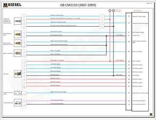
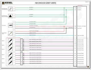
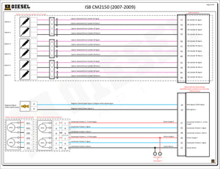
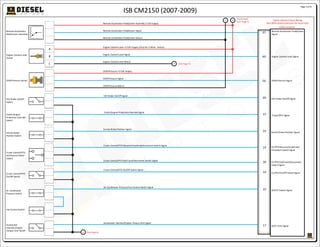
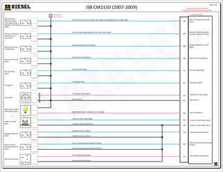
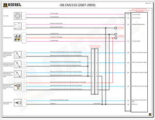
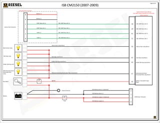
This document provides an electrical circuit diagram and descriptions for a Cummins ISB CM2150 diesel engine from 2007-2009. It includes:
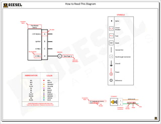
1) A key listing abbreviations for wire colors and component names/numbers.
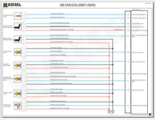
2) A multi-page diagram showing engine sensors, actuators and their electrical connections to the ECM and vehicle wiring.
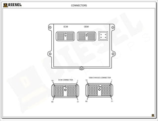
3) Pinouts and descriptions for the ECM and other connectors.
The diagram provides technicians with information to trace circuitry and diagnose electrical issues. Abbreviations standardize the representation of colors for consistent identification.


![MAZDA 2 2014-MZR 1.5].pdfmanual-completo](https://cdn.slidesharecdn.com/ss_thumbnails/mazda22014-mzr1-241103153341-cbacf6e3-thumbnail.jpg?width=640&height=640&fit=bounds)


