Downloaded 20 times
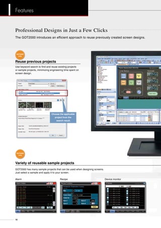
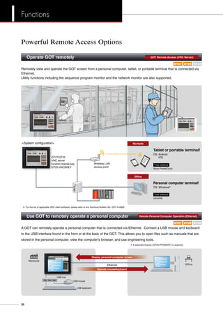
![GT27 15inch 12.1inch
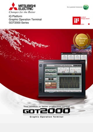
Advanced model with multi-touch gesture functions
The GOT2000 inherits all the features of our popular GOT1000 series, and introduces a more refined
and advanced function set.The powerful and flexible lineup includes GOTs with various features and
communication options to tackle any application you may encounter.
XGA SVGA
GT25 High performance, cost efficient, mid-range model
RS-232
Ethernet
RS-422/485
Bus
MELSECNET/H
CC-Link IE
CC-Link
RS-232
Ethernet
RS-422/485
Bus
MELSECNET/H
CC-Link IE
CC-Link
RS-232
Ethernet
RS-422/485
12.1inch
SVGA
GT2512-STBA
GT2512-STBD
Resolution: 800×600
Display color: 65536 colors
GT23 10.4inch
Unchallenged cost performance
VGA
GT2310-VTBA
GT2310-VTBD
Resolution: 640×480
Display color: 65536 colors
8.4inch
VGA
GT2308-VTBA
GT2308-VTBD
Resolution: 640×480
Display color: 65536 colors
NEW
GT2715-XTBA
GT2715-XTBD
Resolution: 1024×768
Display color: 65536 colors
GT2712-STBA
GT2712-STBD
GT2712-STWA [White model]
GT2712-STWD [White model]
Resolution: 800×600
Display color: 65536 colors
Coming soon
4
Line up](https://image.slidesharecdn.com/got2000series-140609125725-phpapp02/85/Pulpit-operatorski-Mitsubishi-GOT2000-HMI-4-320.jpg)
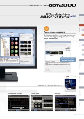
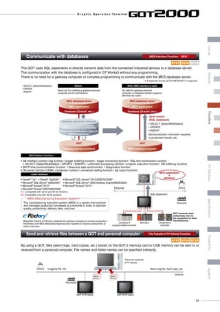
![SoftGOT
10.4inch 8.4inch
GT SoftGOT2000 is an HMI software that allows GOT2000
functions to operate on a personal computer or panel computer.
8 GT SoftGOT2000 Version1 is included with GT Works3.
A separate license key must be mounted during use.
Resolution: 640 to 1920 × 480 to 1200
Display color: 65536 colors
GOT2000 compatible HMI software
2000 Version1
Multi-mediaGesture Video/RGB Sound output External I/O
Turn your personal computer into a GOT!
SVGA
GT2708-STBA
GT2708-STBD
Resolution: 800×600
Display color:
65536 colors
VGA
GT2708-VTBA
GT2708-VTBD
Resolution: 640×480
Display color:
65536 colors
SVGA
GT2710-STBA
GT2710-STBD
Resolution: 800×600
Display color:
65536 colors
VGA
GT2710-VTBA
GT2710-VTBD
GT2710-VTWA [White model]
GT2710-VTWD [White model]
Resolution: 640×480
Display color: 65536 colors
10.4inch 8.4inch
Sound output External I/O
VGA
GT2510-VTBA
GT2510-VTBD
GT2510-VTWA [White model]
GT2510-VTWD [White model]
Resolution: 640×480
Display color: 65536 colors
VGA
GT2508-VTBA
GT2508-VTBD
GT2508-VTWA [White model]
GT2508-VTWD [White model]
Resolution: 640×480
Display color: 65536 colors
Compliant with safety standards including UL Standards, shipping standards (to be obtained soon),
and radio laws. For inquiries relating to the status of conforming to UL, cUL, and CE directives and
shipping directives, please contact your local sales office.
NEW NEW
5
G r a p h i c O p e r a t i o n Te r m i n a l
LineupFASolutionsSpecificationsSupportProductlistFeaturesFunctions](https://image.slidesharecdn.com/got2000series-140609125725-phpapp02/85/Pulpit-operatorski-Mitsubishi-GOT2000-HMI-5-320.jpg)
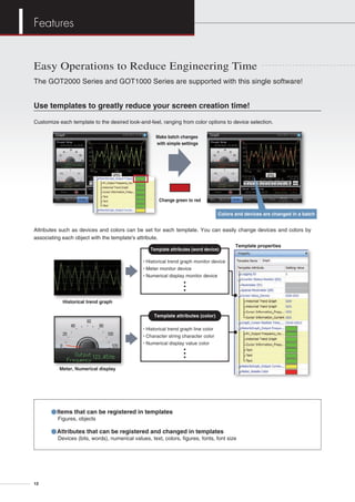
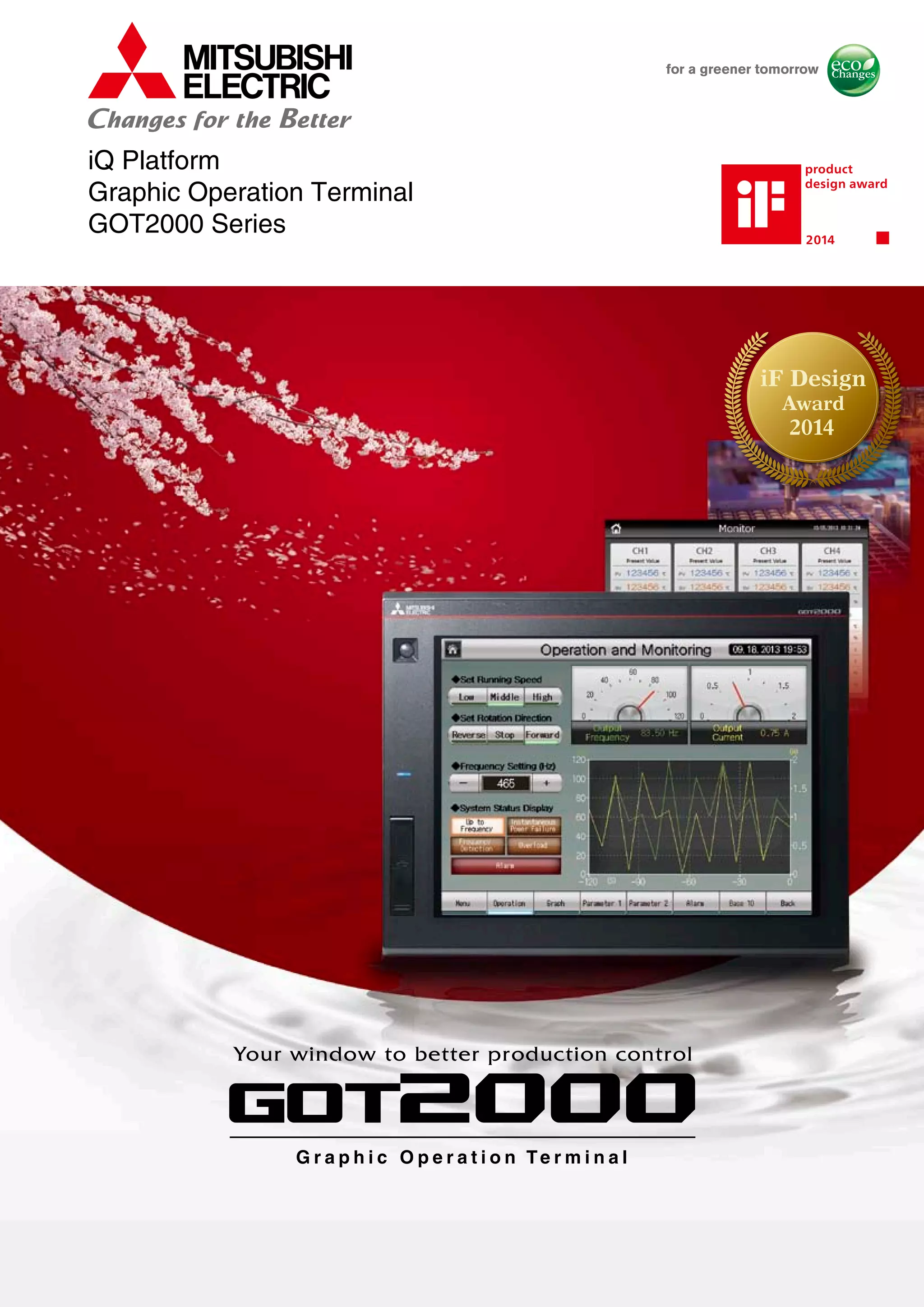
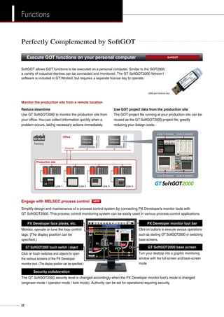
![Quickly identify cause of errors by reviewing recordings of the production line.
Event trigger device: ON
120
seconds
before
Error!
Attach a video camera to the GOT, and record
the production line before and after trouble occurs.
Play the video on the GOT. Play the video on the alarm display screen.
Record and playback in high quality VGA resolution.
120
seconds
after
Alarm display screen
10/01/2013 10:00 Error B110
10/01/2013 10:10 Error B112
10/01/2013 9:55 Error B110
Video
search
[Recording specifications]
<Before-after event recording> …A total of 240 seconds of images can be recorded, including 120 seconds before and
after a system error occurs. (When event trigger device turns on.)
Standard mode …Two types of recording modes are available. Recording size VGA (640×480), frame rate max. 15fps,
or recording size QVGA (320×240), frame rate max. 30fps.
Longtime mode …Approximately two days worth of video image can be recorded. The recording size is QVGA
(320×240), frame rate is 15fps.
When errors occur on-site, a check sheet or manual can be displayed on the GOT with instructions on how to restore the
system. This can reduce the downtime.
Display documents on the GOT
Supported file format
doc, xls, ppt, pdf, jpg, bmp
Record the worksite state Multimedia Function
Review documents at the production site Document Display
GT23GT27 GT25
GT23GT27 GT25
G r a p h i c O p e r a t i o n Te r m i n a l
15
LineupFASolutionsSpecificationsSupportProductlistFeaturesFunctions](https://image.slidesharecdn.com/got2000series-140609125725-phpapp02/85/Pulpit-operatorski-Mitsubishi-GOT2000-HMI-15-320.jpg)
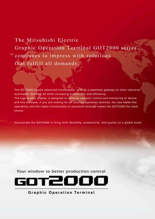
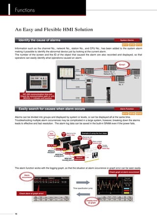
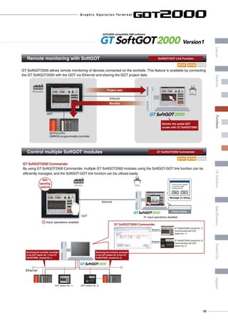
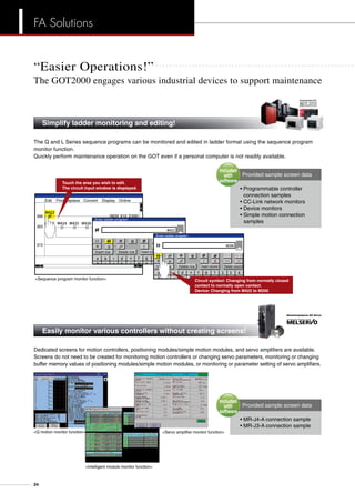
![When an error occurs, monitor the ladder program and identify the cause of error. There is no need for a personal
computer on the production floor.
Edit Find/Replace Convert Display Online
Insert row Delete row Insert column Delete column
Enter ladder program
Enter ladder program
Insert row Delete row Insert column Delete column
Just touch the GOT screen and easily edit the ladder program to make simple changes.
Sensor
X20
M20M20
Circuit input
[ ]
a ecb d f g
ENT
1 2
6
3 4
5 7h i j k l m n
X20
Sensor
X10
Change the device number from
X10 to X20.
Review
Target models ……… MELSEC-Q Series (excluding QnPHCPU/QnPRHCPU/QnUDPVCPU), L Series,
Motion controller Q Series (programmable controller CPU section)
Monitor and edit ladder programs without a personal computer Sequence Program Monitor
GT23GT27 GT25
G r a p h i c O p e r a t i o n Te r m i n a l
17
LineupFASolutionsSpecificationsSupportProductlistFeaturesFunctions](https://image.slidesharecdn.com/got2000series-140609125725-phpapp02/85/Pulpit-operatorski-Mitsubishi-GOT2000-HMI-17-320.jpg)
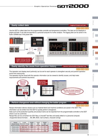
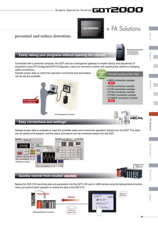
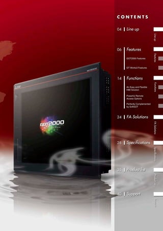
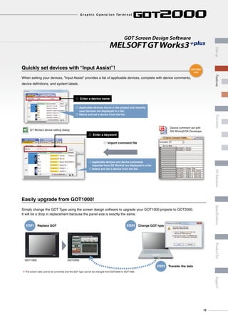
![“More Options!”
The GOT2000 engages various industrial devices to support maintenance
wReduce spare parts cost
ePowerful support for maintenance
iQ Platform, the next generation integrated platformMitsubishi FA Integrated Platform
optimizes the front line of production
qReduce engineering costs
The FA integrated software suite, MELSOFT iQ Works, in which
the GT Works3 screen design software is included, allows for
efficient design of systems and monitor screens for each controller.
A single GOT2000 can take the place for several types of
monitor units, thus greatly reducing costs for spare parts.
The GOT2000 has a variety of useful maintenance functions
including the “Q motion monitor function” and “CNC monitor
function”. Use these reliable functions for
troubleshooting.
Controllers compatible with iQ Platform
GOT2000
Quickly reduce total costs by creating a
seamless integrated engineering environment
• System Management Software [MELSOFT Navigator]
• Programmable Controller Engineering Software [MELSOFT GX Works2]
• Motion Controller Engineering Software [MELSOFT MT Works2]
• Servo Setup Software [MELSOFT MR Configurator2]
• Inverter Setup Software [FR Configurator2]
• Screen Design Software for Graphic Operation Terminal [MELSOFT GT Works3]
• Robot Engineering Software [MELSOFT RT ToolBox2 mini]
With high speed control and convenience fully assured, controllers compatible with the iQ Platform and the GOT2000
are the keys to higher productivity at lower cost. PLCs, motion controllers, CNCs, robot controllers, and C controllers
are integrated into one as controllers compatible with the iQ Platform. The GOT2000 integrates different types of
monitor units that were previously connected to each controller.
Coming soon
I improved Quality
I intelligent Quick
I innovation Quest
CNCProgrammable controller C ControllerRobotMotion controller
Unique functions designed for iQ Platform controllers!
FA Solutions
26](https://image.slidesharecdn.com/got2000series-140609125725-phpapp02/85/Pulpit-operatorski-Mitsubishi-GOT2000-HMI-26-320.jpg)
![Item Specifications
Operating ambient temperature ]1 0 to 55°C ]2
Storage ambient temperature -20 to 60°C
Operating ambient humidity 10 to 90% RH, non-condensing
Storage ambient humidity 10 to 90% RH, non-condensing
Vibration resistance
Compliant with
JIS B3502 and
IEC61131-2
Frequency Acceleration Half-amplitude Sweep count
Under intermittent
vibration
5 to 8.4Hz – 3.5mm 10 times each
in X, Y and Z
directions8.4 to 150Hz 9.8m/s2
–
Under continuous
vibration
5 to 8.4Hz – 1.75mm
–
8.4 to 150Hz 4.9m/s2
–
Shock resistance Compliant with JIS B3502, IEC 61131-2 (147 m/s2 (15G), 3 times each in X, Y and Z directions)
Operating atmosphere No oily smoke, corrosive gas or combustible gas, less conductive dust, away from direct sunlight (the same in storage)
Operating altitude ]3 2000m or less
Installation location Inside control panel
Overvoltage category ]4 II or less
Pollution level ]5 2 or less
Cooling method Self-cooling
Grounding Type D grounding (100Ω or less). Connect to panel if unable to ground.
]1 The operating ambient temperature includes the temperature
inside the enclosure of the control panel to which the GOT is
installed.
]2 The maximum operating ambient temperature should be 5°C
lower than that shown in the table on the left when connecting
to a multimedia unit (GT27-MMR-Z), MELSECNET/H
communication unit (GT15-J71LP23-25 or GT15-J71BR13) or
CC-Link communication unit (GT15-J61BT13).
]3 Do not operate or store the GOT unit in pressurized
environments where the pressure exceeds 0m elevation
atmospheric pressure, as this could result in abnormal operation.
Do not pressurize inside the control panel for air purge cleaning.
The pressure could raise the surface sheet, making the touch
panel difficult to operate or causing the sheet to come off.
]4 Assuming that the device is connected at some point between a
public power distribution network and local system equipment.
CategoryII applies to devices that are supplied with power from
fixed equipment. The surge withstand voltage is 2,500V for
devices with ratings up to 300V.
]5 Index that indicates the level of foreign conductive matter in the
operating environment of the device. Pollution level 2 denotes
an environment contaminated only by non-conductive matter
which may, under certain conditions, become temporarily
conductive due to condensation.
Do not use or store the GOT under direct sun light or in
an environment with excessively high temperature, dust,
humidity or vibration.
For inquiries relating to the status of conforming to UL, cUL,
and CE directives and shipping directives, please contact
your local sales office.
General specifications
GT27
Power supply specifications
Item
Specifications
GT2715-XTBA
GT2712-STBA
GT2712-STWA
GT2710-STBA
GT2710-VTBA
GT2710-VTWA
GT2708-STBA
GT2708-VTBA
GT2715-XTBD
GT2712-STBD
GT2712-STWD
GT2710-STBD
GT2710-VTBD
GT2710-VTWD
GT2708-STBD
GT2708-VTBD
Power supply voltage 100 to 240VAC (+10%, -15%) 24VDC (+25%, -20%)
Power supply frequency 50/60Hz ±5% –
Power
consumption
Maximum load 51W or less 44W or less 41W or less 41W or less 48W or less 45W or less 42W or less 39W or less
Stand alone 25W 19W 17W 15W 23W 18W 15W 13W
Stand alone with backlight off 10W 10W 10W 10W 8W 8W 8W 8W
Inrush current
40A or less
(3ms, ambient
temperature 25°C,
maximum load)
60A or less (2ms, ambient temperature 25°C, maximum load) 5A or less (20ms, ambient temperature 25°C, maximum load)
Allowable momentary power failure time Within 20ms (100VAC or more) Within 10ms
Noise immunity Noise voltage 1500Vp-p, noise width 1μs by noise simulator with noise frequency 25 to 60Hz Noise voltage 500Vp-p, noise width 1μs by noise simulator with noise frequency 25 to 60Hz
Withstand voltage 1500VAC for 1 minute between power supply terminal and ground 350VAC for 1 minute between power supply terminal and ground
Insulation resistance 10MΩ or higher with an insulation resistance tester (500VDC between power supply terminal and ground)
Screen size Model A B Remarks
15 GT2715 383.5 (15.10) 282.5 (11.12) Same dimensions as GT1695, GT1595.
12.1 GT2712 302 (11.89) 228 (8.98) Same dimensions as GT1685, GT1585, A985GOT.
10.4 GT2710 289 (11.38) 200 (7.87) Same dimensions as GT167M, GT157M, A97MGOT.
8.4 GT2708 227 (8.94) 176 (6.93) Same dimensions as GT1665, GT1565.
Unit: mm (inch)
Unit: mm (inch)
A
+2
0
B
+2
0Panel opening
Panel cutting dimensions
External dimensions
GT2715 GT2712 GT2710 GT2708
316 (12.44)
246(9.69)
227(8.94)10
(0.39)
10
(0.39)
52
(2.05)6
(0.24)
241 (9.49)
241 (9.49)
301 (11.85)
397 (15.63)
322 (12.68)
300(11.81)
20
(0.79)
322 (12.68)
10
(0.39)
6(0.24)
60(2.36)
46(1.81)
382 (15.04)
281(11.06)10(0.39)
10
(0.39)
10
(0.39)
303 (11.93)
208 (8.19)
228 (8.98)
288 (11.34)
218(8.58)
199(7.83)10
(0.39)
10
(0.39)
52
(2.05)6
(0.24)
241 (9.49)
166 (6.54)
226 (8.90)
171.6
(6.76)
175(6.89)
194(7.64)
10
(0.39)
10
(0.39)
52
(2.05)6
(0.24)
37.5 (1.48)
37.5 (1.48)
28
Specifications](https://image.slidesharecdn.com/got2000series-140609125725-phpapp02/85/Pulpit-operatorski-Mitsubishi-GOT2000-HMI-28-320.jpg)
![Performance specifications
Item
Specifications
GT2715-XTBA
GT2715-XTBD
GT2712-STBA
GT2712-STBD
GT2712-STWA
GT2712-STWD
GT2710-STBA
GT2710-STBD
GT2710-VTBA
GT2710-VTBD
GT2710-VTWA
GT2710-VTWD
GT2708-STBA
GT2708-STBD
GT2708-VTBA
GT2708-VTBD
Display
section ]1 ]2
Display device TFT color LCD
Screen size 15 12.1 10.4 8.4
Resolution XGA: 1024×768 dots SVGA: 800×600 dots VGA: 640×480 dots
SVGA: 800×600
dots
VGA: 640×480 dots
Display size
304.1(12.0)(W)×
228.1(8.98)(H)
mm(inch)
246.0(9.685)(W)×184.5(7.264)(H)
mm(inch)
211.2(8.315)(W)×158.4(6.236)(H) mm(inch)
170.9(6.728)(W) x 128.2(5.047)(H)
mm(inch)
Number of characters
16-dot standard font:
64 chars. × 48 lines (2-byte)
12-dot standard font:
85 chars. × 64 lines (2-byte)
16-dot standard font: 50 chars. × 37 lines (2-byte)
12-dot standard font: 66 chars. × 50 lines (2-byte)
16-dot standard font: 40 chars. × 30 lines (2-byte)
12-dot standard font: 53 chars. × 40 lines (2-byte)
16-dot standard font:
50 chars. × 37 lines (2-byte)
12-dot standard font:
66 chars. × 50 lines (2-byte)
16-dot standard font:
40 chars. × 30 lines (2-byte)
12-dot standard font:
53 chars. × 40 lines (2-byte)
Display color 65536 colors
Intensity adjustment 32-level adjustment
Backlight LED (not replaceable)
Backlight life ]4 Approx. 60000 hours or more (Time for display intensity reaches 50% at ambient temperature of 25°C)
Touch panel ]3
Type Analog resistive film
Key size Minimum 2 × 2 dots (per key)
Simultaneous press Maximum 2 points
Life 1 million times or more (operating force 0.98N or less)
Human
sensor
Detection distance 1m –
Detection temperature Temperature difference between human body and ambient air: 4°C or higher –
User memory
User memory
capacity
Memory for storage (ROM): 57MB
Memory for operation (RAM): 128MB
Life (No. of writings) 100000 times
Internal clock accuracy ±90 sec/month (ambient temperature 25°C)
Battery
GT11-50BAT lithium battery
Life Approx. 5 years (ambient temperature 25°C)
Built-in
interface
RS-232 1ch Transmission speed: 115200/57600/38400/19200/9600/4800bps Connector shape: D-sub 9-pin (male)
RS-422/485 1ch Transmission speed: 115200/57600/38400/19200/9600/4800bps Connector shape: D-sub 9-pin (female)
Ethernet 1ch Data transfer method: 10BASE-T/100BASE-TX Connector shape: RJ-45 (modular jack)
USB (host)
2ch (front face/rear face) 1ch (rear face) 2ch (front face/rear face) 1ch (rear face) 2ch (front face/rear face)
Maximum transfer speed: High-Speed 480Mbps Connector shape: USB-A
USB (device)
1ch (front face) 1ch (rear face) 1ch (front face) 1ch (rear face) 1ch (front face)
Maximum transfer speed: High-Speed 480Mbps Connector shape: USB Mini-B
SD card 1ch SDHC compliant (maximum 32GB)
Extension interface For communication unit/option unit mounting
Auxiliary extension I/F For option unit mounting
Side interface For communication unit mounting
Buzzer output Single tone (tone, tone length adjustable)
POWER LED Emission color: 2 colors (blue, orange)
Protective structure Front: IP67F ]5 In control panel: IP2X
External dimensions
397(15.63)(W)×
300(11.81)(H)×60(D)
mm(inch)
316(12.44)(W)×246(9.69)(H)×52(2.05)(D) mm(inch) 303(11.93)(W)×218(8.58)(H)×52(2.05)(D) mm(inch) 241(9.49)(W)×194(7.64)(H)×52(2.05)(D) mm(inch)
Panel cutting dimensions
383.5(15.10)(W)×
282.5(11.12)(H)
mm(inch)
302(11.89)(W)×228(8.98)(H) mm(inch) 289(11.38)(W)×200(7.87)(H) mm(inch) 227(8.94)(W)×176(6.93)(H) mm(inch)
Weight (excl. mounting brackets) 4.5kg 2.4kg 2.1kg 1.5kg
Compatible software package GT Designer3 Version1.112S or later
]1 On LCD panels, bright dots (permanently lit) and black dots (never lit) generally appear. Because the number of display elements that exist on an LCD panel is large, it is not possible to reduce appearance of the
bright and black dots to zero. Individual differences in LCD panels may cause differences in color, uneven brightness and flickering. Note that these are characteristics of LCD panels and it does not mean the products
are defective or damaged.
]2 Flickering may occur due to vibration or shock, or depending on the display colors.
]3 The life of using a stylus pen is 100,000. Use a stylus pen meeting the following specifications.
• Material: Polyacetal resin • Pen point radius: 0.8mm or more
]4 Using the GOT screen saver/backlight OFF functions prevents screen burn-in and extends backlight life.
]5 Pressing PUSH mark firmly and locking the USB environmentally protective cover makes it conform to IP67F. (The USB interface conforms to IP2X when the cover is open.)
However, this does not guarantee protection in all users' environments. The unit may not be used in an environment where it is exposed to splashing oil or chemicals for a long time or it is soaked with oil mist.
Components names q Display screen
w Touch panel
e USB interface (host/front face)
] Excluding white model
r USB interface (device/front face)
] Excluding white model
t POWER LED
y Human sensor
(GT2715/GT2712 only)
u Unit mounting bracket
i Reset switch
o S. MODE switch
!0 SD card access LED
!1 SD card interface
!2 SD card cover
!3 Battery
!4 Side interface
!5 USB interface (host/rear face)
!6 Cable clamp mounting hole
!7 Terminating resistor setting switch
(inside the cover)
!8 Auxiliary extension I/F
!9 Extension interface
@0 Power supply terminal
@1 Ethernet interface
@2 RS-232 interface
@3 RS-422/485 interface
@4 USB interface (device/rear face)
] White model only
!0
GT2715/GT2712
qw
t
@3
!9
i
!7!8
o
!1
!2
!3
!4
!5
@2 @1 @0
u u
u
y
u
e
r
@4
!6
!0
!1
!2
!3
!4
!5
!6
GT2710
@3 @2@1 @0
u u!9
i
!8
!7
ou u
@4
qw
t
e
r
GT2708
!0
!1!2!3
!7
!4
!5
@3 @2@1 @0
u u!9
i
!8
ou u
qw
t
er
!6
G r a p h i c O p e r a t i o n Te r m i n a l
29
LineupFASolutionsSpecificationsSupportProductlistFeaturesFunctions](https://image.slidesharecdn.com/got2000series-140609125725-phpapp02/85/Pulpit-operatorski-Mitsubishi-GOT2000-HMI-29-320.jpg)
![Item Specifications
Operating ambient temperature ]1 0 to 55°C ]2
Storage ambient temperature -20 to 60°C
Operating ambient humidity 10 to 90% RH, non-condensing
Storage ambient humidity 10 to 90% RH, non-condensing
Vibration resistance
Compliant with
JIS B3502 and
IEC61131-2
Frequency Acceleration Half-amplitude Sweep count
Under intermittent
vibration
5 to 8.4Hz – 3.5mm 10 times each
in X, Y and Z
directions8.4 to 150Hz 9.8m/s2
–
Under continuous
vibration
5 to 8.4Hz – 1.75mm
–
8.4 to 150Hz 4.9m/s2
–
Shock resistance Compliant with JIS B3502, IEC 61131-2 (147 m/s2 (15G), 3 times each in X, Y and Z directions)
Operating atmosphere No oily smoke, corrosive gas or combustible gas, less conductive dust, away from direct sunlight (the same in storage)
Operating altitude ]3 2000m or less
Installation location Inside control panel
Overvoltage category ]4 II or less
Pollution level ]5 2 or less
Cooling method Self-cooling
Grounding Type D grounding (100Ω or less). Connect to panel if unable to ground.
]1 The operating ambient temperature includes the temperature
inside the enclosure of the control panel to which the GOT is
installed.
]2 The maximum operating ambient temperature should be 5°C
lower than that shown in the table on the left when connecting
to a MELSECNET/H communication unit (GT15-J71LP23-25
or GT15-J71BR13) or CC-Link communication unit (GT15-
J61BT13).
]3 Do not operate or store the GOT unit in pressurized
environments where the pressure exceeds 0m elevation
atmospheric pressure, as this could result in abnormal
operation. Do not pressurize inside the control panel for air
purge cleaning. The pressure could raise the surface sheet,
making the touch panel difficult to operate or causing the sheet
to come off.
]4 Assuming that the device is connected at some point
between a public power distribution network and local system
equipment.
CategoryII applies to devices that are supplied with power from
fixed equipment. The surge withstand voltage is 2,500V for
devices with ratings up to 300V.
]5 Index that indicates the level of foreign conductive matter in the
operating environment of the device. Pollution level 2 denotes
an environment contaminated only by non-conductive matter
which may, under certain conditions, become temporarily
conductive due to condensation.
Do not use or store the GOT under direct sun light or in
an environment with excessively high temperature, dust,
humidity or vibration.
For inquiries relating to the status of conforming to UL, cUL,
and CE directives and shipping directives, please contact
your local sales office.
General specifications
GT25
Power supply specifications
Item
Specifications
GT2510-VTBA
GT2510-VTWA
GT2508-VTBA
GT2508-VTWA
GT2510-VTBD
GT2510-VTWD
GT2508-VTBD
GT2508-VTWD
Power supply voltage 100 to 240VAC (+10%, -15%) 24VDC (+25%, -20%)
Power supply frequency 50/60Hz ±5% –
Power
consumption
Maximum load 34W or less 31W or less 33W or less 31W or less
Stand alone 12W 11W 10W 8W
Stand alone with backlight off 7W 7W 6W 6W
Inrush current 60A or less (2ms, ambient temperature 25°C, maximum load) 5A or less (20ms, ambient temperature 25°C, maximum load)
Allowable momentary power failure time Within 20ms (100VAC or more) WWithin 10ms
Noise immunity Noise voltage 1500Vp-p, noise width 1μs by noise simulator with noise frequency 25 to 60Hz Noise voltage 500Vp-p, noise width 1μs by noise simulator with noise frequency 25 to 60Hz
Withstand voltage 1500VAC for 1 minute between power supply terminal and ground 350VAC for 1 minute between power supply terminal and ground
Insulation resistance 10MΩ or higher with an insulation resistance tester (500VDC between power supply terminal and ground)
Screen size Model A B Remarks
10.4 GT2510 289 (11.38) 200 (7.87) Same dimensions as GT167M, GT157M, A97MGOT.
8.4 GT2508 227 (8.94) 176 (6.93) Same dimensions as GT1665, GT1565.
GT2510 GT2508
Unit: mm (inch)
Unit: mm (inch)
A
+2
0
B
+2
0Panel opening
303 (11.93)
208 (8.19)
228 (8.98)
288 (11.34)
218(8.58)
199(7.83)10
(0.39)
10
(0.39)
52
(2.05)6
(0.24)
241 (9.49)
166 (6.54)
226 (8.90)
171.6
(6.76)
175(6.89)
194(7.64)
10
(0.39)
10
(0.39)
52
(2.05)6
(0.24)
37.5 (1.48)
37.5 (1.48)
Panel cutting dimensions
External dimensions
30
Specifications](https://image.slidesharecdn.com/got2000series-140609125725-phpapp02/85/Pulpit-operatorski-Mitsubishi-GOT2000-HMI-30-320.jpg)
![Performance specifications
Item
Specifications
GT2510-VTBA
GT2510-VTBD
GT2510-VTWA
GT2510-VTWD
GT2508-VTBA
GT2508-VTBD
GT2508-VTWA
GT2508-VTWD
Display
section ]1 ]2
Display device TFT color LCD
Screen size 10.4 8.4
Resolution VGA: 640×480 dots
Display size 211.2(8.315)(W)×158.4(6.236)(H) mm(inch) 170.9(6.728)(W) x 128.2(5.047)(H) mm(inch)
Number of characters
16-dot standard font: 40 chars. × 30 lines (2-byte)
12-dot standard font: 53 chars. × 40 lines (2-byte)
Display color 65536 colors
Intensity adjustment 32-level adjustment
Backlight LED (not replaceable)
Backlight life ]4 Approx. 60000 hours or more (Time for display intensity reaches 50% at ambient temperature of 25°C)
Touch panel ]3
Type Analog resistive film
Key size Minimum 2 × 2 dots (per key)
Simultaneous press Simultaneous press prohibited ]5 (only 1 point can be pressed)
Life 1 million times or more (operating force 0.98N or less)
User memory
User memory
capacity
Memory for storage (ROM): 32MB
Memory for operation (RAM): 80MB
Life (No. of writings) 100000 times
Internal clock accuracy ±90 sec/month (ambient temperature 25°C)
Battery
GT11-50BAT lithium battery
Life Approx. 5 years (ambient temperature 25°C)
Built-in
interface
RS-232 1ch Transmission speed: 115200/57600/38400/19200/9600/4800bps Connector shape: D-sub 9-pin (male)
RS-422/485 1ch Transmission speed: 115200/57600/38400/19200/9600/4800bps Connector shape: D-sub 9-pin (female)
Ethernet 1ch Data transfer method: 10BASE-T/100BASE-TX Connector shape: RJ-45 (modular jack)
USB (host)
2ch (front face/rear face) 1ch (rear face) 2ch (front face/rear face) 1ch (rear face)
Maximum transfer speed: High-Speed 480Mbps Connector shape: USB-A
USB (device)
1ch (front face) 1ch (rear face) 1ch (front face) 1ch (rear face)
Maximum transfer speed: High-Speed 480Mbps Connector shape: USB Mini-B
SD card 1ch SDHC compliant (maximum 32GB)
Extension interface For communication unit/option unit mounting
Side interface For communication unit mounting
Buzzer output Single tone (tone, tone length adjustable)
POWER LED Emission color: 2 colors (blue, orange)
Protective structure Front: IP67F ]6 In control panel: IP2X
External dimensions 303(11.93)(W)×218(8.58)(H)×52(2.05)(D) mm(inch) 241(9.49)(W)×194(7.64)(H)×52(2.05)(D) mm(inch)
Panel cutting dimensions 289(11.38)(W)×200(7.87)(H) mm(inch) 227(8.94)(W)×176(6.93)(H) mm(inch)
Weight (excl. mounting brackets) 2.1kg 1.5kg
Compatible software package GT Designer3 Version1.112S or later
]1 On LCD panels, bright dots (permanently lit) and black dots (never lit) generally appear. Because the number of display elements that exist on an LCD panel is large, it is not possible to reduce appearance of the
bright and black dots to zero. Individual differences in LCD panels may cause differences in color, uneven brightness and flickering. Note that these are characteristics of LCD panels and it does not mean the
products are defective or damaged.
]2 Flickering may occur due to vibration or shock, or depending on the display colors.
]3 The life of using a stylus pen is 100,000. Use a stylus pen meeting the following specifications.
• Material: Polyacetal resin • Pen point radius: 0.8mm or more
]4 Using the GOT screen saver/backlight OFF functions prevents screen burn-in and extends backlight life.
]5 When 2 points on the touch panel are pressed simultaneously, if a switch is located in the middle of the 2 points then the switch will be activated. Therefore, avoid pressing 2 points on the touch panel simultaneously.
]6 Pressing PUSH mark firmly and locking the USB environmentally protective cover makes it conform to IP67F. (The USB interface conforms to IP2X when the cover is open.)
However, this does not guarantee protection in all users' environments. The unit may not be used in an environment where it is exposed to splashing oil or chemicals for a long time or it is soaked with oil mist.
Components names
q Display screen
w Touch panel
e USB interface (host/front face)
] Excluding white model
r USB interface (device/front face)
] Excluding white model
t POWER LED
y Unit mounting bracket
u Reset switch
i S. MODE switch
o SD card access LED
!0 SD card interface
!1 SD card cover
!2 Battery
!3 Side interface
!4 USB interface (host/rear face)
!5 Cable clamp mounting hole
!6 Terminating resistor setting switch
(inside the cover)
!7 Extension interface
!8 Power supply terminal
!9 Ethernet interface
@0 RS-232 interface
@1 RS-422/485 interface
@2 USB interface (device/rear face)
] White model only
GT2510
qw
GT2508
!3
!0!1!2
!4
!5
!5
@2 @1 @0 !9 !8
@2 !9 !8
o
!3
!0!1
!4
o
!2
uy
y y
yy
t
er
t
er
!6
!7
y y!6!7
qw
@1 @0
u ⑥ i i
G r a p h i c O p e r a t i o n Te r m i n a l
31
LineupFASolutionsSpecificationsSupportProductlistFeaturesFunctions](https://image.slidesharecdn.com/got2000series-140609125725-phpapp02/85/Pulpit-operatorski-Mitsubishi-GOT2000-HMI-31-320.jpg)
![Item Specifications
Operating ambient temperature ]1 0 to 55°C
Storage ambient temperature -20 to 60°C
Operating ambient humidity 10 to 90% RH, non-condensing ]2
Storage ambient humidity 10 to 90% RH, non-condensing ]2
Vibration resistance
Compliant with
JIS B3502 and
IEC61131-2
Frequency Acceleration Half-amplitude Sweep count
Under intermittent
vibration
5 to 8.4Hz – 3.5mm 10 times each
in X, Yand Z
directions8.4 to 150Hz 9.8m/s2
–
Under continuous
vibration
5 to 8.4Hz – 1.75mm
–
8.4 to 150Hz 4.9m/s2
–
Shock resistance Compliant with JIS B3502, IEC 61131-2 (147 m/s2
(15G), 3 times each in X, Y and Z directions)
Operating atmosphere No oily smoke, corrosive gas or combustible gas, less conductive dust, away from direct sunlight (the same in storage)
Operating altitude ]3 2000m or less
Installation location Inside control panel
Overvoltage category ]4 II or less
Pollution level ]5 2 or less
Cooling method Self-cooling
Grounding Type D grounding (100Ω or less). Connect to panel if unable to ground.
]1 The operating ambient temperature includes the temperature
inside the enclosure of the control panel to which the GOT is
installed.
]2 If ambient temperature exceeds 40°C, absolute humidity should
not exceed 90% at 40°C.
]3 Do not operate or store the GOT unit in pressurized environments
where the pressure exceeds 0m elevation atmospheric
pressure, as this could result in abnormal operation. Do not
pressurize inside the control panel for air purge cleaning. The
pressure could raise the surface sheet, making the touch panel
difficult to operate or causing the sheet to come off.
]4 Assuming that the device is connected at some point between a
public power distribution network and local system equipment.
CategoryII applies to devices that are supplied with power from
fixed equipment. The surge withstand voltage is 2,500V for
devices with ratings up to 300V.
]5 Index that indicates the level of foreign conductive matter in the
operating environment of the device. Pollution level 2 denotes an
environment contaminated only by non-conductive matter which
may, under certain conditions, become temporarily conductive
due to condensation.
General specifications
GT23
Power supply specifications
External dimensions
Panel cutting dimensions
Item
Specifications
GT2310-VTBA GT2308-VTBA GT2310-VTBD GT2308-VTBD
Power supply voltage 100 to 240VAC (+10%, -15%) 24VDC (+25%, −20%)
Power supply frequency 50/60Hz ±5% –
Power
consumption
Maximum load 18W or less 11W or less 16W or less 11W or less
Stand alone 15W 9W 13W 8W
Stand alone with backlight off 8W 6W 7W 6W
Inrush current 40A or less (4ms, ambient temperature 25°C, maximum load) 40A or less (2ms, ambient temperature 25°C, maximum load)
Allowable momentary power failure time Within 20ms (100VAC or more) Within 10ms
Noise immunity Noise voltage 1500Vp-p, noise width 1μs by noise simulator with noise frequency 25 to 60Hz Noise voltage 500Vp-p, noise width 1μs by noise simulator with noise frequency 25 to 60Hz
Withstand voltage 1500VAC for 1 minute between AC external terminal and ground 350VAC for 1 minute between power supply terminal and ground
Insulation resistance 10MΩ or higher with an insulation resistance tester (500VDC between power supply terminal and ground)
Screen size Model A B Remarks
10.4 GT2310 289 (11.38) 200 (7.87) Same dimensions as GT167M, GT157M, A97MGOT.
8.4 GT2308 227 (8.94) 176 (6.93) Same dimensions as GT1665, GT1565.
GT2310 GT2308
Unit: mm (inch)
Unit: mm (inch)
A
+2
0
B
+2
0Panel opening
175(6.89)
194(7.64)
10
(0.39)
10
(0.39)
241 (9.49)
166 (6.54)
166 (6.54)
226 (8.90)
56(2.20)
6
(0.24)
199(7.84)10
(0.39)
10
(0.39)
303 (11.93)
208 (8.19)
228 (8.98)
288 (11.34)
218(8.58)
56(2.20)
6
(0.24)
Do not use or store the GOT under direct sun light or in
an environment with excessively high temperature, dust,
humidity or vibration.
For inquiries relating to the status of conforming to UL,
cUL, and CE directives and shipping directives, please
contact your local sales office.
32
Specifications](https://image.slidesharecdn.com/got2000series-140609125725-phpapp02/85/Pulpit-operatorski-Mitsubishi-GOT2000-HMI-32-320.jpg)
![Performance specifications
Item
Specifications
GT2310-VTBA
GT2310-VTBD
GT2308-VTBA
GT2308-VTBD
Display
section ]1 ]2
Display device TFT color LCD
Screen size 10.4 8.4
Resolution VGA: 640×480 dots
Display size 211.2(8.315)(W)×158.4(6.236)(H) mm(inch) 170.9(6.728)(W) × 128.2(5.047)(H) mm(inch)
Number of characters
16-dot standard font: 40 chars. × 30 lines (2-byte)
12-dot standard font: 53 chars. × 40 lines (2-byte)
Display color 65536 colors
Intensity adjustment 16-level adjustment
Backlight LED (not replaceable)
Backlight life ]4 Approx. 50000 hours or more (Time for display intensity reaches 50% at ambient temperature of 25°C)
Touch panel ]3
Type Analog resistive film
Key size Minimum 2 × 2 dots (per key)
Simultaneous press Simultaneous press prohibited ]5 (only 1 point can be pressed)
Life 1 million times or more (operating force 0.98N or less)
User memory
User memory
capacity
Memory for storage (ROM): 9MB
Memory for operation (RAM): 9MB
Life (No. of writings) 100000 times
Internal clock accuracy ±90 sec/month (ambient temperature 25°C)
Battery
GT11-50BAT lithium battery
Life Approx. 5 years (ambient temperature 25°C)
Built-in
interface
RS-232 1ch Transmission speed: 115200/57600/38400/19200/9600/4800bps Connector shape: D-sub 9-pin (male)
RS-422/485 1ch Transmission speed: 115200/57600/38400/19200/9600/4800bps Connector shape: D-sub 9-pin (female)
Ethernet 1ch Data transfer method: 10BASE-T/100BASE-TX Connector shape: RJ-45 (modular jack)
USB (host)
1ch
Maximum transfer speed: Full-Speed 12Mbps Connector shape: USB-A
USB (device)
1ch
Maximum transfer speed: Full-Speed 12Mbps Connector shape: USB Mini-B
SD card 1ch SDHC compliant (maximum 32GB)
Buzzer output Single tone (tone length adjustable)
POWER LED Emission color: 2 colors (blue, orange)
Protective structure Front: IP67F ]6 In control panel: IP2X
External dimensions 303(11.93)(W)×218(8.58)(H)×56(2.20)(D) mm(inch) 241(9.49)(W)×194(7.64)(H)×56(2.20)(D) mm(inch)
Panel cutting dimensions 289(11.38)(W)×200(7.87)(H) mm(inch) 227(8.94)(W)×176(6.93)(H) mm(inch)
Weight (excl. mounting brackets) 1.9kg 1.5kg
Compatible software package GT Designer3 Version1.112S or later
Components names
q Display screen
w Touch panel
e POWER LED
r Unit mounting bracket
t S. MODE switch
y SD card access LED
u SD card interface
i SD card cover
o USB interface (host)
!0 USB interface (device)
!1 Cable clamp mounting hole
!2 Terminating resistor setting switch
(inside the cover)
!3 Battery
!4 Power supply terminal
!5 Ethernet interface
!6 RS-232 interface
!7 RS-422/485 interface
]1 On LCD panels, bright dots (permanently lit) and black dots (never lit) generally appear. Because the number of display elements that exist on an LCD panel is large, it is not possible to reduce appearance of the
bright and black dots to zero. Individual differences in LCD panels may cause differences in color, uneven brightness and flickering. Note that these are characteristics of LCD panels and it does not mean the products
are defective or damaged.
]2 Flickering may occur due to vibration or shock, or depending on the display colors.
]3 The life of using a stylus pen is 100,000. Use a stylus pen meeting the following specifications.
• Material: Polyacetal resin • Pen point radius: 0.8mm or more
]4 Using the GOT screen saver/backlight OFF functions prevents screen burn-in and extends backlight life.
]5 When 2 points on the touch panel are pressed simultaneously, if a switch is located in the middle of the 2 points then the switch will be activated. Therefore, avoid pressing 2 points on the touch panel simultaneously.
]6 This does not guarantee protection in all users' environments. The unit may not be used in an environment where it is exposed to splashing oil or chemicals for a long time or it is soaked with oil mist.
GT2310 / GT2308
qw
e
t
y
u
i
!0
o
!7 !6 !5 !4
r !3 r
r r
!2 !1
G r a p h i c O p e r a t i o n Te r m i n a l
33
LineupFASolutionsSpecificationsSupportProductlistFeaturesFunctions](https://image.slidesharecdn.com/got2000series-140609125725-phpapp02/85/Pulpit-operatorski-Mitsubishi-GOT2000-HMI-33-320.jpg)
![Category Function name Necessary devices ]1
GT27 GT25 GT23 GT SoftGOT2000
Screendesign
Figure/objectfunctions
Figure ● ● ● ●
Logo text ● ● ● ●
Touch switch ● ● ● ●
Lamp ● ● ● ●
Numerical display, Numerical input ● ● ● ●
Text display, Text input ● ● ● ●
Date display, Time display (Battery) ● ● ● ●
Comment display ● ● ● ●
Parts display (SD card or USB memory) ● ● ● ●
Parts movement (SD card or USB memory) ● ● ● ●
Historical data list display ● ● ● ●
Simple alarm display ● ● ● ●
System alarm display ● ● ● ●
Alarm display (user) (SD card or USB memory, battery) ● ● ● ●
Alarm display (system) (SD card or USB memory, battery) ● ● ● ●
Level ● ● ● ●
Panelmeter ● ● ● ●
Line graph ● ● ● ●
Trend graph ● ● ● ●
Bar graph ● ● ● ●
Statistic bar graph ● ● ● ●
Statistic pie graph ● ● ● ●
Scatter graph ● ● ● ●
Historical trend graph ● ● ● ●
Slider NEW ● ● ● ●
Document display SD card ● ● – ●
FunctionsperformedonbackgroundofGOT
Logging (SD card or USB memory, battery) ● ● ● ●
Recipe (SD card or USB memory) ● ● ● ●
Device data transfer ● ● ● ●
Trigger action ● ● ● ●
Time action (SD card or USB memory) ● ● ● ●
Hard copy
File output SD card or USB memory ● ● ● ●
Serial printer output NEW ● ● ● ●]2
PictBridge printer output NEW Printer unit ● ● – ●]2
Project/screen script ● ● ● ●
Object script ● ● ● ●
Functionsusedwithperipheraldevices
Barcode function ● ● ● ●
RFID function ● ● ● ●
Remote personal computer operation function (Ethernet) License ● ● – –
Remote personal computer operation function (serial) RGB input unit or Video/RGB input unit ● – – –
GOT remote access function (VNC server function) License ● ● – –
Video display function Video input unit or Video/RGB input unit ● – – –
RGB display function RGB input unit or Video/RGB input unit ● – – –
Multimedia function Multimedia unit, CF card ● – – –
External I/O function External I/O unit ● ● – –
Operation panel function NEW External I/O unit ● ● – ●
RGB output function RGB output unit ● – – –
Report function
Serial printer output NEW ● ● ● ●]3
PictBridge printer output NEW Printer unit ● ● – ●]3
Sound output function Sound output unit ● ● – ●
Server function, Client function ● ● – –
Mail send function ● ● – ●
FTP server function (SD card or USB memory) ● ● ● –
File transfer (FTP client) function SD card or USB memory ● ● ● –
MES interface function NEW License, (SD card) ● ● – –
GOTfunctions
Base screen ● ● ● ●
Overlap window ● ● ● ●
Superimpose window ● ● ● ●
Dialog window ● ● ● ●
Key window ● ● ● ●
Language switching ● ● ● ●
System information ● ● ● ●
Operator authentication (SD card or USB memory) ● ● ● ●
Operation log SD card or USB memory ● ● ● ●
Startup logo ● ● ● ●
Kana-kanji conversion NEW ● ● – ●
FA transparent ● ● ● –
SoftGOT-GOT link ● ● – ●
Backup/Restore SD card or USB memory ● ● ● –
Multi-channel function ●
4ch (Up to 3 units)
●
4ch (Up to 3 units)
●
2ch (No units can be mounted)
–
Station No. switching ● ● ● ●
Screen gesture function ● – – –
Object gesture function ● – – –
Vertical display Coming soon ● ● ● –
Debugfunctions
Device monitor ● ● ● –
Sequence program monitor (Ladder) SD card or USB memory ● ● – –
Sequence program monitor (SFC) SD card or USB memory ● ● – –
Network monitor ● ● – –
Intelligent module monitor ● ● – –
Servo amplifier monitor ● ● – –
Q motion monitor ● ● – –
Motion SFC monitor SD card or USB memory ● ● – –
CNC monitor Coming soon ●]4 ●]4 – –
CNC data I/O Coming soon SD card or USB memory ●]4 ●]4 – –
CNC machining program edit Coming soon ●]4 ●]4 – –
Log viewer (SD card or USB memory) ● ● – –
MELSEC-FX list editor ● ● ● –
FX ladder monitor ● ● – –
MELSEC-L troubleshooting ● ● – –
]1 Necessary units when using GT27, GT25, or GT23 are shown. Parenthesized devices will be required depending on conditions of use.
]2 Data is output to the printer that is recognized by the personal computer.
]3 CSV files are saved in the virtual drive of the personal computer so that it is recommended to output the files to printers.
]4 Only the GOTs with SVGA or higher resolution are supported.
● : Supported – : Not supported
For details of functions, supported controllers, and connection types, please refer to the GOT2000 Series Manual or Help.
Function list
34
Specifications / Product list](https://image.slidesharecdn.com/got2000series-140609125725-phpapp02/85/Pulpit-operatorski-Mitsubishi-GOT2000-HMI-34-320.jpg)
![GOT model name
GOTs
GT27 15 X T B A-
GT27
Advanced model with multi-touch gesture
functions
GT25
High performance, cost efficient, mid-range
model
GT23 Unchallenged cost performance
Code Screen size
15 15
12 12.1
10 10.4
08 8.4
Code Resolution
X XGA
S SVGA
V VGA
Code Display section
T TFT color
Code Panel color
B Black
W White
Code Power supply type
A 100 to 240VAC
D 24VDC
]For inquiries relating to the status of conforming to UL, cUL, and CE directives
and shipping directives, please contact your local sales office.
Category Model name Screen size Display section Display color Panel color Power supply Remarks
GT27
GT2715
GT2715-XTBA NEW
15 XGA
TFT color 65536 colors
Black
AC
Multimedia Video/RGB
compliant
Multi-touch compliant
GT2715-XTBD NEW DC
GT2712
GT2712-STBA
12.1 SVGA
Black
AC
GT2712-STBD DC
GT2712-STWA
White
AC
GT2712-STWD DC
GT2710
GT2710-STBA
10.4 SVGA
Black
AC
GT2710-STBD DC
GT2710-VTBA
10.4 VGA
AC
GT2710-VTBD DC
GT2710-VTWA
White
AC
GT2710-VTWD DC
GT2708
GT2708-STBA
8.4 SVGA
Black
AC
GT2708-STBD DC
GT2708-VTBA
8.4 VGA
AC
GT2708-VTBD DC
GT25
GT2512
GT2512-STBA Coming soon
12.1 SVGA Black
AC
–
GT2512-STBD Coming soon DC
GT2510
GT2510-VTBA NEW
10.4 VGA
Black
AC
GT2510-VTBD NEW DC
GT2510-VTWA NEW
White
AC
GT2510-VTWD NEW DC
GT2508
GT2508-VTBA NEW
8.4 VGA
Black
AC
GT2508-VTBD NEW DC
GT2508-VTWA NEW
White
AC
GT2508-VTWD NEW DC
GT23
GT2310
GT2310-VTBA
10.4 VGA Black
AC
–
GT2310-VTBD DC
GT2308
GT2308-VTBA
8.4 VGA Black
AC
GT2308-VTBD DC
G r a p h i c O p e r a t i o n Te r m i n a l
35
LineupFASolutionsSpecificationsSupportProductlistFeaturesFunctions](https://image.slidesharecdn.com/got2000series-140609125725-phpapp02/85/Pulpit-operatorski-Mitsubishi-GOT2000-HMI-35-320.jpg)
![Communication units
Option units
Product name Model name Specifications
Applicable model
GT27 GT25 GT23
Serial communication unit
GT15-RS2-9P RS-232 serial communication unit (D-sub 9-pin male) ● ● –
GT15-RS4-9S RS-422/485 serial communication unit (D-sub 9-pin female) ]1 ]2 ● ● –
GT15-RS4-TE
RS-422/485 serial communication unit (terminal block) ]1
Usable only when connecting to temperature controllers/indicating controllers via
RS-485 or in GOT multi-drop connection
● ● –
Q bus connection unit
GT15-QBUS Q bus connection (1ch) unit standard model ● ● –
GT15-QBUS2 Q bus connection (2ch) unit standard model ● ● –
GT15-75QBUSL Q bus connection (1ch) unit slim model ]3 ● ● –
GT15-75QBUS2L Q bus connection (2ch) unit slim model ]3 ● ● –
MELSECNET/H communication unit
GT15-J71LP23-25 Normal station unit (optical loop) ● ● –
GT15-J71BR13 Normal station unit (coaxial bus) ● ● –
CC-Link IE Controller Network communication unit GT15-J71GP23-SX Normal station unit (optical loop) ● ● –
CC-Link IE Field Network communication unit GT15-J71GF13-T2 Intelligent device station unit ● ● –
CC-Link communication unit GT15-J61BT13 Intelligent device station unit CC-LINK Ver. 2 compliant ● ● –
Serial multi-drop connection unit GT01-RS4-M For GOT multi-drop connection ● ● –
Product name Model name Specifications
Applicable model
GT27 GT25 GT23
Printer unit GT15-PRN
USB slave (PictBridge) for printer connection, 1ch
Cable for connection between printer unit and printer (3m) included
●
NEW
● –
Multimedia unit GT27-MMR-Z For video input (NTSC/PAL) 1ch, Record video images/play video files ● – –
Video input unit GT27-V4-Z For video input (NTSC/PAL) 4ch ● – –
RGB input unit GT27-R2-Z For analog RGB input 2ch ● – –
Video/RGB input unit GT27-V4R1-Z For video input (NTSC/PAL) 4ch / analog RGB 1ch input ● – –
RGB output unit GT27-ROUT-Z For analog RGB output 1ch ● – –
Sound output unit GT15-SOUT For sound output (φ3.5 stereo pin jack) ● ● –
External I/O unit
GT15-DIOR
For external I/O devices and operation panel connection
(negative common input / source type output)
● ● –
GT15-DIO
For external I/O devices and operation panel connection
(positive common input / sink type output)
● ● –
]1 The unit may not be able to be used depending on the connection destination. Please refer to the GOT2000 Series Connection Manual.
]2 The unit cannot be used when connecting to temperature controllers/indicating controllers via RS-485 (2-wire type).
]3 The unit cannot be used stacked on other units.
Software
Product name Model name Contents
HMI screen design software
MELSOFT GT Works3
SW1DND-GTWK3-E
English
Version
Standard license product
DVD-ROMSW1DND-GTWK3-EA Volume license product ]1
SW1DND-GTWK3-EAZ Additional license product ]1 ]6
FA Integrated Engineering Software
MELSOFT iQ Works ]2 ]3 SW1DND-IQWK-E
English
Version
Standard license product (Version1.77F or later) DVD-ROM
License key for GT SoftGOT2000 ]4 GT27-SGTKEY-U USB port licence key
PC remote operation
function (Ethernet) license ]5 GT25-PCRAKEY 1 license
VNC® server function license ]5 GT25-VNCSKEY 1 license (License for GOT remote access function)
MES interface function license ]5 GT25-MESIFKEY NEW 1 license
]1 The desired number of licenses (2 or more) can be purchased. For details, please contact your local sales office.
]2 Volume license product and additional license product are also available. For more details, please refer to the MELSOFT iQ Works catalog (L(NA)08232).
]3 The product includes the following software.
• System Management Software [MELSOFT Navigator] • Programmable Controller Engineering Software [MELSOFT GX Works2]
• Motion Controller Engineering Software [MELSOFT MT Works2] • Servo Setup Software [MELSOFT MR Configurator2]
• Inverter Setup Software [FR Configurator2] • Screen Design Software for Graphic Operation Terminal [MELSOFT GT Works3]
• Robot Engineering Software [MELSOFT RT ToolBox2 mini]
]4 To use GT SoftGOT2000, a license key for GT SoftGOT2000 is necessary for each personal computer.
]5 1 license is required for 1 GOT unit.
]6 This product does not include the DVD-ROM. Only the license certificate with the product ID No. is issued.
36
Product list](https://image.slidesharecdn.com/got2000series-140609125725-phpapp02/85/Pulpit-operatorski-Mitsubishi-GOT2000-HMI-36-320.jpg)
![Options
Product name Model name Specifications
Applicable model
GT27 GT25 GT23
Protective sheet ]1
GT27-15PSGC NEW For 15
Surface treatment: anti-glare
Sheet color: transparent
USB environmental protection cover area: open
Number of sheets included in a set: 5
● – –
GT25-12PSGC For 12.1 ● ●
Coming soon
–
GT25-10PSGC For 10.4 ● ● –
GT25-08PSGC For 8.4 ● ● –
GT27-15PSCC NEW For 15
Surface treatment: clear
Sheet color: transparent
USB environmental protection cover area: open
Number of sheets included in a set: 5
● – –
GT25-12PSCC For 12.1 ● ●
Coming soon
–
GT25-10PSCC For 10.4 ● ● –
GT25-08PSCC For 8.4 ● ● –
GT25-12PSCC-UC For 12.1 Surface treatment: clear
Sheet color: transparent
USB environmental protection cover area: closed ]2
Number of sheets included in a set: 5
● ●
Coming soon
–
GT25-10PSCC-UC For 10.4 ● ● ●
GT25-08PSCC-UC For 8.4 ● ● ●
USB environmental protection cover GT25-UCOV Protective cover for USB interface on GOT front panel (for replacement) ● ● –
Protective cover for oil ]3
GT20-15PCO NEW For 15 ● – –
GT20-12PCO For 12.1 ● ●
Coming soon
–
GT20-10PCO For 10.4 ● ● ●
GT20-08PCO For 8.4 ● ● ●
Stand
GT15-90STAND For 15 ● – –
GT15-80STAND For 12.1 ● ●
Coming soon
–
GT15-70STAND For 10.4/8.4 ● ● ●
Memory card
SD card
L1MEM-2GBSD 2GB SD memory card for GOT ● ● ●
L1MEM-4GBSD 4GB SDHC memory card for GOT ● ● ●
CF card
GT05-MEM-128MC 128MB CF card for GT27-MMR-Z ● – –
GT05-MEM-256MC 256MB CF card for GT27-MMR-Z ● – –
GT05-MEM-512MC 512MB CF card for GT27-MMR-Z ● – –
GT05-MEM-1GC 1GB CF card for GT27-MMR-Z ● – –
GT05-MEM-2GC 2GB CF card for GT27-MMR-Z ● – –
GT05-MEM-4GC 4GB CF card for GT27-MMR-Z ● – –
GT05-MEM-8GC 8GB CF card for GT27-MMR-Z ● – –
GT05-MEM-16GC 16GB CF card for GT27-MMR-Z ● – –
Memory card adapter GT05-MEM-ADPC CF card→memory card (TYPE II) conversion adapter for GT27-MMR-Z ● – –
Attachment
GT15-70ATT-98
For 10.4
For conversion from GT168M, GT158M, A985GOT ]4 ● ● ●
GT15-70ATT-87 For conversion from A870GOT-SWS/TWS, A8GT-70GOT-TB/TW/SB/SW ● ● ●
GT15-60ATT-97
For 8.4
For conversion from GT167M, GT157M, A97MGOT ● ● ●
GT15-60ATT-96 For conversion from A960GOT ● ● ●
GT15-60ATT-87 For conversion from A870GOT-EWS, A8GT-70GOT-EB/EW, A77GOT-EL, A77GOT-EL-S5/S3 ● ● ●
GT15-60ATT-77 For conversion from A77GOT-CL, A77GOT-CL-S5/S3, A77GOT-L, A77GOT-L-S5/S3 ● ● ●
Battery GT11-50BAT Battery for backup of SRAM data, clock data, and system status log data ●
(For replacement)
●
(For replacement)
●
(Option)
]1 The while model does not have the front USB interface. It is recommended to use the products that the USB environmental protection cover area is closed.
]2 When using the product with the USB environmental protection cover area closed, the front USB interface cannot be used.
]3 Check if the protective cover for oil can be used in the actual environment before use. When using the cover, the front USB interface and human sensor cannot be used.
]4 Including the GP250M and GP260M manufactured by Digital Electronics Corporation.
G r a p h i c O p e r a t i o n Te r m i n a l
37
LineupFASolutionsSpecificationsSupportProductlistFeaturesFunctions](https://image.slidesharecdn.com/got2000series-140609125725-phpapp02/85/Pulpit-operatorski-Mitsubishi-GOT2000-HMI-37-320.jpg)
![Cables
Product name Model name
Cable
length
Recommended
product ]1 Specifications
Applicable model
GT27 GT25 GT23
QCPU bus
connection
cable
QCPU connection cable
GOT-to-GOT
connection cable
GT15-QC06B 0.6m
Between QCPU and GOT
Between GOT and GOT
● ● –
GT15-QC12B 1.2m
GT15-QC30B 3m
GT15-QC50B 5m
GT15-QC100B 10m
QCPU connection cable
GOT-to-GOT
connection cable
(for long distance connection)
GT15-QC150BS 15m
Between QCPU and GOT (for long-distance connection)
A9GT-QCNB required
Between GOT and GOT (for long-distance connection)
● ● –
GT15-QC200BS 20m
GT15-QC250BS 25m
GT15-QC300BS 30m
GT15-QC350BS 35m
Bus extension connector box A9GT-QCNB – – Attach to PLC main base when using QCPU and GOT long-distance connection ● ● –
Ferrite core set for Q bus cable GT15-QFC – –
Attach to GOT-A900 bus connection cable when replacing existing GOT-A900
with GOT2000 (two-pack)
● ● –
RS-485 terminal block conversion unit
FA-LTBGT2R4CBL05 0.5m
RS-485 terminal block conversion unit
With cable for connection between RS-422/485 (connector) of GOT2000 and
RS-485 terminal block conversion unit
● ● –FA-LTBGT2R4CBL10 1m
FA-LTBGT2R4CBL20 2m
RS-422 conversion cable
FA-CNV2402CBL 0.2m Between QCPU/L02SCPU(-P) and RS-422 cable (GT01-CMR4-25P, GT10-
CMR4-25P)
Between L6ADP-R2 and RS-422 cable (GT01-CMR4-25P, GT10-CMR4-25P)
[MINI-DIN6 pin and D-sub 25-pin]
● ● ●
FA-CNV2405CBL 0.5m
RS-422
cable
QnA/A/FXCPU direct
connection cable
Computer link
connection cable
CC-Link(G4)
connection cable
GT01-C30R4-25P 3m
–
Between QnA/ACPU/motion controller CPU (A series)/FXCPU and GOT
Between RS-422 conversion cable (FA-CNVMCBL) and GOT
Between serial communication module and GOT
Between peripheral connection module (AJ65BT-G4-S3) and GOT
[Between D-sub 25-pin and D-sub 9-pin]
● ● ●
GT01-C100R4-25P 10m
GT01-C200R4-25P 20m
GT01-C300R4-25P 30m
Computer link
connection cable
GT09-C30R4-6C 3m
Between serial communication module and GOT
Between computer link module and GOT
[Between loose wire and D-sub 9-pin]
● ● ●
GT09-C100R4-6C 10m
GT09-C200R4-6C 20m
GT09-C300R4-6C 30m
FXCPU direct
connection cable
FXCPU communication expansion
board connection cable
GT01-C10R4-8P 1m
–
Between FXCPU and GOT
Between FXCPU communication expansion board and GOT
[Between MINI-DIN 8-pin connector and D-sub 9-pin]
● ● ●
GT01-C30R4-8P 3m
GT01-C100R4-8P 10m
GT01-C200R4-8P 20m
GT01-C300R4-8P 30m
RS-232
cable
Q/LCPU direct
connection cable
GT01-C30R2-6P 3m –
Between Q/LCPU and GOT
Between L6ADP-R2 and personal computer (GT SoftGOT2000)
[Between MINI-DIN 6-pin and D-sub 9-pin]
● ● ●
FXCPU communication expansion
board connection cable
FXCPU communication special
adapter connection cable
GT01-C30R2-9S 3m –
Between FXCPU communication expansion board and GOT/personal computer
(GT SoftGOT2000)
Between FXCPU communication special adapter and GOT/personal computer
(GT SoftGOT2000)
[Between D-sub 9-pin and D-sub 9-pin]
● ● ●
FXCPU communication special
adapter connection cable
GT01-C30R2-25P 3m –
Between FXCPU communication special adapter and GOT/personal computer
(GT SoftGOT2000)
[Between D-sub 25-pin connector and D-sub 9-pin]
● ● ●
Computer link
connection cable
CC-Link(G4)
connection cable
GT09-C30R2-9P 3m
Between serial communication module and GOT
Between computer link module and GOT
Between peripheral connection module (AJ65BT-R2N) and GOT
[Between D-sub 9-pin and D-sub 9-pin]
● ● ●
Computer link
connection cable
GT09-C30R2-25P 3m
Between serial communication module and GOT
Between computer link module and GOT
[Between D-sub 25-pin and D-sub 9-pin]
● ● ●
External I/O unit connection
conversion cable
GT15-C03HTB 0.3m
Between external I/O unit (GT15-DIO) and GOT-A900 external I/O interface unit
connection cable (A8GT-C05TK, A8GT-C30TB, user-fabricated cable)
● ● –
Analog RGB cable GT15-C50VG 5m Between external monitor, personal computer and vision sensor and GOT ● – –
USB cable
Data transfer cable
Printer connection
cable
GT09-C30USB-5P 3m
Between personal computer (screen design software) and GOT
Between personal computer (GT SoftGOT2000) and QnU/L/FXCPU
Between PictBridge-compatible printer and printer unit (GT15-PRN)
[Between USB-A and USB Mini-B]
● ● ●
]1 FA-LTBGT2R4CBLM, FA-CNV240MCBL are developed by Mitsubishi Electric Engineering Company Limited and sold through your local sales office.
The other products listed are developed by Mitsubishi Electric Systems Service Co., LTD. and sold through your local sales office.
38
Product list](https://image.slidesharecdn.com/got2000series-140609125725-phpapp02/85/Pulpit-operatorski-Mitsubishi-GOT2000-HMI-38-320.jpg)

![FA Products
Product Specifications
Program capacity
Number of I/O points [X/Y], number of I/O device points [X/Y]
Basic instruction processing speed (LD instruction)
External connection interface
Function module
Module extension style
Network
10k steps to 1000k steps
256 points to 4096 points/8192 points
120 ns to 1.9 ns
USB (all models equipped), Ethernet, RS-232, memory card, extended SRAM cassette
I/O, analog, high-speed counter, positioning, simple motion, temperature input, temperature control, network module
Building block type
Ethernet, CC-Link IE controller network, CC-Link IE field netwo rk, CC-Link,
CC-Link/LT, MELSECNET/H, SSCNETⅢ (/H), AnyWire, RS-232, RS-422
PLC MELSEC-Q Series Universal Model
◎Realize high-speed, high-accuracy machine control with various iQ Platform compatible controllers and multiple CPUs.
◎Easily connect to GOTs and Programming tools using built-in Ethernet port.
◎25 models from 10k step small capacity to 1000k step large capacity, are available.
◎Seamless communication and flexible integration at any network level.
Introducing the high-speed QCPU (QnUDVCPU) for faster processing of large data volumes.
Product specifications
Program capacity
Number of input/output points [X/Y]
Number of input/output device points [X/Y]
Basic instruction processing speed (LD instruction)
External connection interface
Function modules
Unit expansion style
Network
20 k steps/60 k steps/260 k steps
1024 points/4096 points
8192 points
60 ns/ 40 ns/ 9.5 ns
USB, Ethernet, RS-232, SD memory card, CC-Link (L26CPU-BT/PBT)
I/O, analog, high-speed counter, positioning, simple motion, temperature control, network module
Base-less structure
Ethernet, CC-Link IE Field network, CC-Link, CC-Link/LT, SSCNETIII(/H), RS-232, RS-422
PLC MELSEC-L Series
◎CPU equipped as a standard with various functions including counter, positioning and CC-Link.
◎The base-less structure with high degree of freedom saves space in the control panel.
◎Easily confirm the system status and change the settings with the display unit.
◎Ten models are available in program capacities from 20 k steps to 260 k steps.
“Light Flexible”condensing various functions easily and flexibly.
Product specifications
Program capacity
Number of input/output points
Basic instruction processing speed
External connection interface
Built-in functions
Extended functions
Unit expansion style
Network
16k steps (FX3S) to 64 k steps (FX3U/FX3UC)
10 points (FX3S) to 384 points (FX3U/FX3UC with CC-Link)
0.21μs (FX3S) to 65 ns (FX3U/FX3UC)
RS-422, USB (FX3S/FX3G/FX3GC/FX3GE only), Ethernet (FX3GE only), CC-Link/LT (FX3UC-32MT-LT(-2) only)
I/O, high-speed counter input, positioning pulse output, analog (FX3GE only)
I/O, analog, temperature control, high-speed counter, positioning, network
Backplane-less design
Ethernet, CC-Link, CC-Link/LT, SSCNETⅢ, CANopen, J1939, RS-232C, RS-422, RS-485, MODBUS
PLC MELSEC-F Series
◎Supporting small-scale control from 10 points to 384 points (using CC-Link) with an outstanding cost performance.
◎Wide range of options available for additional functions required by your system.
◎Easy to use and highly reliable. More than 12 million units have shipped worldwide. (April 2013)
◎Small-scale control is available in various networks such as CC-Link, Ethernet, and MODBUS.
All-in-One Micro Programmable Controller equipped with all necessary functions in a compact body
43](https://image.slidesharecdn.com/got2000series-140609125725-phpapp02/85/Pulpit-operatorski-Mitsubishi-GOT2000-HMI-43-320.jpg)
![Product Specifications
Power supply specifications
Command interface
Control mode
Speed frequency response
Tuning function
Safety function
Compatible servo motor
1-phase/3-phase 200V AC, 1-phase 100V AC, 3-phase 400V AC
SSCNET Ⅲ/H, SSCNET Ⅲ (compatible in J3 compatibility mode), CC-Link IE Field
Network interface with Motion, pulse train, analog
Position/Speed/Torque/Fully closed loop
2.5kHz
Advanced one-touch tuning, advanced vibration suppression control Ⅱ, robust filter, etc.
STO, SS1
SS2, SOS, SLS, SBC, SSM (compatible when combined with motion controller)
Rotary servo motor (rated output: 0.05 to 22kW), linear servo motor (continuous
thrust 50 to 3000N), direct drive motor (rated torque: 2 to 240N • m)
AC Servo Mitsubishi General-Purpose AC Servo MELSERVO-J4 Series
Industry-leading level of high performance servo
◎Industry-leading level of basic performance: Speed frequency response (2.5kHz), 4,000,000 (4,194,304p/rev) encoder
◎Advanced one-touch tuning function achieves the one-touch adjustment of advanced vibration suppression controlⅡ, etc.
◎Equipped with large capacity drive recorder and machine diagnosis function for easy maintenance.
◎2-axis and 3-axis servo amplifiers are available for energy-conservative, space-saving, and low-cost machines.
Product Specifications
Inverter capacity
Control method
Output frequency range
Regenerative braking torque
(Maximum tolerable usage rate)
Starting torque
200V class: 0.4kW to 90kW, 400V class: 0.4kW to 500kW
High-carrier frequency PWM control (Select from V/F, advanced flux vector,
real sensor-less vector or PM sensor-less vector control), vector control (when using options)
0.2 to 590Hz (when using V/F control or advanced flux vector control)
200V class: 0.4K to 1.5K (150% at 3%ED) 2.2K/3.7K (100% at 3%ED) 5.5K/7.5K (100% at 2%ED)
11K to 55K (20% continuous) 75K or more (10% continuous), 400V class: 0.4K to 7.5K (100% at 2%ED)
11K to 55K (20% continuous) 75K or more (10% continuous)
200% 0.3Hz (3.7K or less), 150% 0.3Hz (5.5K or more) (when using real sensor-less vector, vector control)
Inverter FR-A800 Series
◎Realize even higher responsiveness during real sensor-less vector control or vector control, and achieve faster operating frequencies.
◎The latest automatic tuning function supports various induction motors and also sensor-less PM motors.
◎The standard model is compatible with EU Safety Standards STO (PLd, SIL2). Add options to support higher level safety standards.
◎A variety of useful functions provide USB memory support and customization with a PLC function.
High-functionality, high-performance inverter
Product Specifications
Drive unit / motor capacity
Control method
Rated speed
Speed fluctuation rate
Position control Command input method
Positioning accuracy
Starting torque
Communication specifications
200V class: 0.1kW to 0.75kW
PM sensor-less vector control (low speed range: high frequency superimposition control)
3000r/min
±0.05% (at 0 to 100% load fluctuation)
The point table method and zero point return enable position control with absolute position commands
±1.8°(machine angle: equivalent to 200 [pulses/rev] resolution, input voltage 200V, wiring length within 5m)
200% (default value)
Built-in: RS-485 communication (Mitsubishi inverter protocol, Modbus-RTU protocol), option: CC-Link communication
Sensor-less Servo FR-E700EX Series, MM-GKR Series
◎Use PM sensor-less vector control to control dedicated PM motors with high accuracy without an encoder.
◎High-accuracy speed control (speed fluctuation rate ±0.05%) and positioning control are supported.
◎The dedicated PM motor (MM-GKR) is quiet as it has no cooling fan. The compact and lightweight unit also supports reduction gears.
◎The standard model supports RS-485 communication. CC-Link communication is supported with an additional option.
Compact and high-function drive unit, low-inertial small capacity sensor-less PM motor
FA Products
44](https://image.slidesharecdn.com/got2000series-140609125725-phpapp02/85/Pulpit-operatorski-Mitsubishi-GOT2000-HMI-44-320.jpg)
![FA Products
Product Specifications.
Frame
Applicable standard
Expansion of UL listed product line-up
Commoditization of internal accessories
Commoditization for AC and DC circuit use
Compact size for easy to use
Measuring Display Unit (MDU) breakers
32-250A Frame
Applicable to IEC, GB, UL, CSA, JIS and etc.
New line-up of 480VAC type with high breaking performance for SCCR requirement
Reduction of internal accessory types from 3 to 1
Common use of 32/63A frame in both AC and DC circuit
Thermal adjustable and electronic circuit breakers are same size as 250AF fixed type
MDU breakers measure, display and transmit energy date to realize energy management.
Low Voltage Circuit Breakers Mitsubishi WS-V Series Molded Case Circuit Breakers, Earth Leakage Circuit Breakers
◎The new electronic circuit breakers can display various measurement items.
◎Improvement of breaking performance with new breaking technology“Expanded ISTAC”.
◎Compliance with global standard for panel and machine export.
◎Commoditization of internal accessories for shorter delivery time and stock reduction.
Technologies based on long year experience realize more improved performance.
Product specifications
Maximum number of control axes (NC axis + spindle + PLC axis)
Maximum number of part system
Maximum number of NC axes per part system
Maximum program capacity
Maximum number of files to store
Number of input/output points
Safety observation function
For detailed information, please refer to: http://www.mitsubishielectric.com/fa/worldwide/index.html
16 axes
Machining center system: 7 systems, Lathe system: 3 systems
8 axes
2,000 kB (5,120 m)
124 files/252 files
4,096 points
Safety signal comparison function, speed monitoring function, duplexed emergency stop
CNC Mitsubishi Numerical Control Unit C70 Series
◎A CNC structured in building block method on iQ Platform.
◎High performance CNC integrated with high-speed PLC offers high-speed control to reduce cycle time.
◎A wide variety of FA products helps construct flexible lines.
iQ Platform compatible CNC to provide TCO reduction effect.
Product Specifications
Model
Machining travel (X×Y×Z)[mm]
Machining travel (U×V)[mm]
Max. taper angle [°]
Max. workpiece dimensions [mm]
Wire diameter [mm]
Dielectric fluid
Footprint (W×D)[mm]
(in)
(in)
(in)
(in)
(in)
※1:Φ0.2(0.08) DD guides and Φ1.5(0.06) jet nozzle are standard equipment.
MV1200R
400(15.7)×300(11.8)×220(8.7)(XY axis OPT-drive specifications)
±60(2.4)×±60(2.4)(OPT-drive specifications)
15°(maximum 200mm)(7.9)
810(31.9)×700(27.6)×215(8.5)
0.1(.004) to 0.3(.012)※1
Water
2025(79.7)×2760(108.7)
EDM Wire EDM MV1200R
Next-generation Innovations of our best selling Performance Machine.
◎Total running cost reduced up to 42%, which is accounted for 90% by filter, ion exchange
resin and power consumption.
◎Improved productivity by an innovative automatic wire threading.
◎Faster machining is realized with improved power-supply performance.
(Rz3. 5μm/Ra0. 45μm with 3cuts)(Rz2. 0μm/Ra0. 28μm with 4cuts)
46](https://image.slidesharecdn.com/got2000series-140609125725-phpapp02/85/Pulpit-operatorski-Mitsubishi-GOT2000-HMI-46-320.jpg)
![Product specifications
Model Name
Drive system
Stroke (X×Y×X) [mm]
Rapid feedrate [m/min]
Processing feedrate [m/min]
Positioning accuracy [mm]
Repeat accuracy [mm]
Rated output [W]
ML3015eX
Flying optic (3-axis beam movement)
3100×1565×150
X,Y axes: Max. 100; Z-axis: Max. 65
Max. 50
0.05 / 500 (X,Y axes)
± 0.01 (X,Y axes)
4500
Laser Processing Machine CO2 2-Dimensional Laser Processing Machine eX-Series
◎Productivity has been dramatically enhanced owing to improved acceleration and the latest control technologies exclusive to Mitsubishi Electric.
◎2 Action Cutting allows for the entire process, from job setup to parts cutting, to be completed in two simple actions.
◎When not processing, the system switches to ECO mode and the resonator stops idling. Minimizes energy consumption, reducing running costs by up to 99%*1
during standby.
*1
: Compared to the previous LV-Series with Mitsubishi's designated benchmark shape.
A global standard CO2 2-dimensional laser processing systems.
47](https://image.slidesharecdn.com/got2000series-140609125725-phpapp02/85/Pulpit-operatorski-Mitsubishi-GOT2000-HMI-47-320.jpg)

![HEAD OFFICE: TOKYO BLDG., 2-7-3, MARUNOUCHI, CHIYODA-KU, TOKYO 100-8310, JAPAN
NAGOYA WORKS: 1-14, YADA-MINAMI 5, HIGASHI-KU, NAGOYA, JAPAN
Sales officeCountry/Region Tel/Fax
MITSUBISHI ELECTRIC AUTOMATION, INC.
500 Corporate Woods Parkway, Vernon Hills, IL 60061, U.S.A.
USA Tel: +1-847-478-2100
Fax: +1-847-478-2253
MITSUBISHI ELECTRIC DO BRASIL COMÉRCIO E SERVIÇOS LTDA.
Rua Jussara, 1750- Bloco B Anexo, Jardim Santa Cecilia, CEP 06465-070, Barueri - SP, Brasil
Brazil Tel: +55-11-4689-3000
Fax: +55-11-4689-3016
MITSUBISHI ELECTRIC AUTOMATION, INC. Mexico Branch
Mariano Escobedo #69, Col.Zona Industrial, Tlalnepantla
Edo, C.P.54030, México
Mexico Tel: +52-55-9171-7600
Fax: +52-55-9171-7649
MITSUBISHI ELECTRIC EUROPE B.V. German Branch
Gothaer Strasse 8, D-40880 Ratingen, Germany
Germany Tel: +49-2102-486-0
Fax: +49-2102-486-1120
MITSUBISHI ELECTRIC EUROPE B.V. UK Branch
Travellers Lane, Hatfield, Hertfordshire, AL10 8XB, U.K.
UK Tel: +44-1707-28-8780
Fax: +44-1707-27-8695
MITSUBISHI ELECTRIC EUROOPE B.V. Italy Branch
Centro Direzionale Colleoni - Palazzo Sirio Viale Colleoni 7,
20864 Agrate Brianza (Milano), Italy
Italy Tel: +39-039-60531
Fax: +39-039-6053-312
MITSUBISHI ELECTRIC EUROPE B.V. Spanish Branch
Carretera de Rubí 76-80-Apdo.420,
08173 Sant Cugat del Vallés (Barcelona), Spain
Spain Tel: +34-935-65-3131
Fax: +34-935-89-1579
MITSUBISHI ELECTRIC EUROPE B.V. French Branch
25, Boulevard des Bouvets, F-92741 Nanterre Cedex, France
France Tel: +33-1-55-68-55-68
Fax: +33-1-55-68-57-57
MITSUBISHI ELECTRIC EUROPE B.V. Czech Branch
Avenir Business Park, Radlicka 751/113e, 158 00 Praha 5, Czech Republic
Czech Republic Tel: +420-251-551-470
Fax: +420-251-551-471
MITSUBISHI ELECTRIC TURKEY A.S. Umraniye Branch
Serifali Mahallesi Nutuk Sokak No:5, TR-34775 Umraniye, Istanbul, Turkey
Turkey Tel: +90-216-526-3990
Fax: +90-216-526-3995
MITSUBISHI ELECTRIC EUROPE B.V. Polish Branch
ul. Krakowska 50, 32-083 Balice, Poland
Poland Tel: +48-12-630-47-00
Fax: +48-12-630-47-01
MITSUBISHI ELECTRIC EUROPE B.V. Russian Branch St. Petersburg Office
Piskarevsky pr. 2, bld 2, lit Sch, BC Benua, office 720; RU-195027 St. Petersburg, Russia
Russia Tel: +7-812-633-3497
Fax: +7-812-633-3499
ADROIT TECHNOLOGIES
20 Waterford Office Park, 189 Witkoppen Road, ZA-Fourways, South Africa
South Africa Tel: +27-11-658-8100
Fax: +27-11-658-8101
MITSUBISHI ELECTRIC AUTOMATION (CHINA) LTD.
No.1386 Hongqiao Road, Mitsubishi Electric Automation Center, Changning District,
Shanghai, China
China Tel: +86-21-2322-3030
Fax: +86-21-2322-3000
SETSUYO ENTERPRISE CO., LTD.
6F., No.105, Wugong 3rd Road, Wugu District, New Taipei City 24889, Taiwan, R.O.C.
Taiwan Tel: +886-2-2299-2499
Fax: +886-2-2299-2509
MITSUBISHI ELECTRIC AUTOMATION KOREA CO., LTD.
1480-6, Gayang-Dong, Gangseo-Gu, Seoul 157-200, Korea
Korea Tel: +82-2-3660-9530
Fax: +82-2-3664-8372/8335
MITSUBISHI ELECTRIC ASIA PTE. LTD.
307, Alexandra Road, Mitsubishi Electric Building, Singapore 159943
Singapore Tel: +65-6473-2308
Fax: +65-6476-7439
MITSUBISHI ELECTRIC FACTORY AUTOMATION (THAILAND) CO., LTD.
12th Floor, SV.City Building, Office Tower 1, No. 896/19 and 20 Rama 3 Road,
Kwaeng Bangpongpang, Khet Yannawa, Bangkok 10120, Thailand
Thailand Tel: +66-2682-6522 to 31
Fax: +66-2682-6020
PT. MITSUBISHI ELECTRIC INDONESIA
Gedung Jaya 11th Floor, JL. MH. Thamrin No.12, Jakarta Pusat 10340, Indonesia
Indonesia Tel: +62-21-3192-6461
Fax: +62-21-3192-3942
MITSUBISHI ELECTRIC VIETNAM COMPANY LIMITED
Unit 01-04, 10th Floor, Vincom Center, 72 Le Thanh Ton Street, District 1,
Ho Chi Minh City, Vietnam
Vietnam Tel: +84-8-3910-5945
Fax: +84-8-3910-5947
MITSUBISHI ELECTRIC INDIA PVT. LTD. Pune Branch
Emerald House, EL-3, J Block, M.I.D.C., Bhosari, Pune, 411026, Maharastra State, India
India Tel: +91-20-2710-2000
Fax: +91-20-2710-2100
MITSUBISHI ELECTRIC AUSTRALIA PTY. LTD.
348 Victoria Road, P.O. Box 11, Rydalmere, N.S.W. 2116, Australia
Australia Tel: +61-2-9684-7777
Fax: +61-2-9684-7245
Mitsubishi Electric Corporation Nagoya Works and Himeji Works are factories certified for ISO14001 (standards for environmental management systems) and ISO9001
(standards for quality assurance management systems).
iQ Platform Graphic Operation Terminal GOT2000 Series
L(NA)08270ENG-B 1404[IP]
New publication, effective Apr. 2014.
Specifications are subject to change without notice.](https://image.slidesharecdn.com/got2000series-140609125725-phpapp02/85/Pulpit-operatorski-Mitsubishi-GOT2000-HMI-52-320.jpg)

The GOT2000 series graphic operation terminal from Mitsubishi Electric offers several advanced functions: 1) It boasts powerful and flexible functionality for monitoring and controlling industrial automation devices, while increasing productivity and efficiency. 2) The high-quality display is optimized for operator control and monitoring, and the new tablet-like design improves usability. 3) Features like multi-touch gestures, video recording capabilities, document display, and data backup to SD cards simplify troubleshooting and maintenance tasks.


![Plc connection guide [unlockplc.com]](https://cdn.slidesharecdn.com/ss_thumbnails/plcconnectionguideunlockplc-150512010529-lva1-app6892-thumbnail.jpg?width=640&height=640&fit=bounds)


