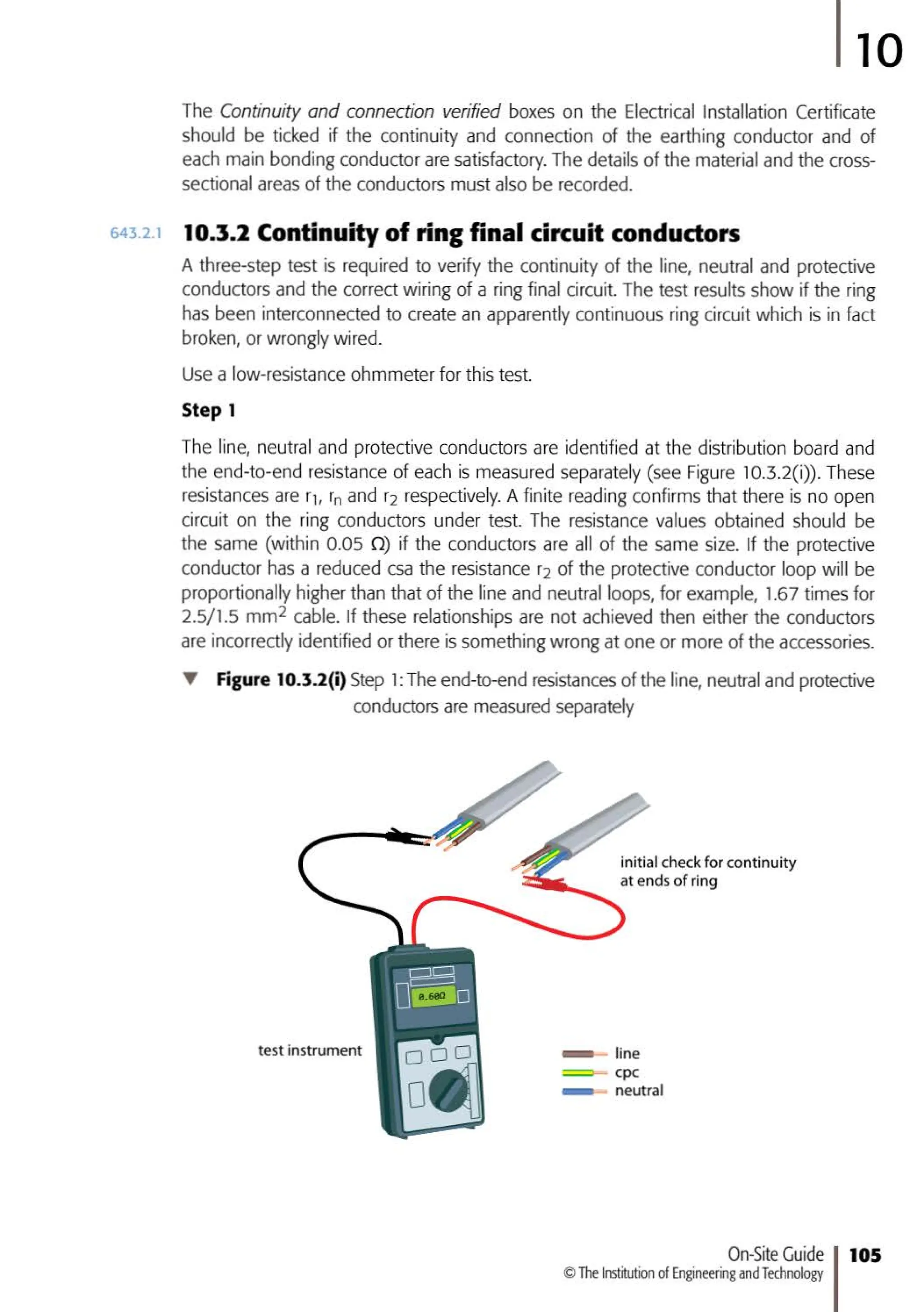
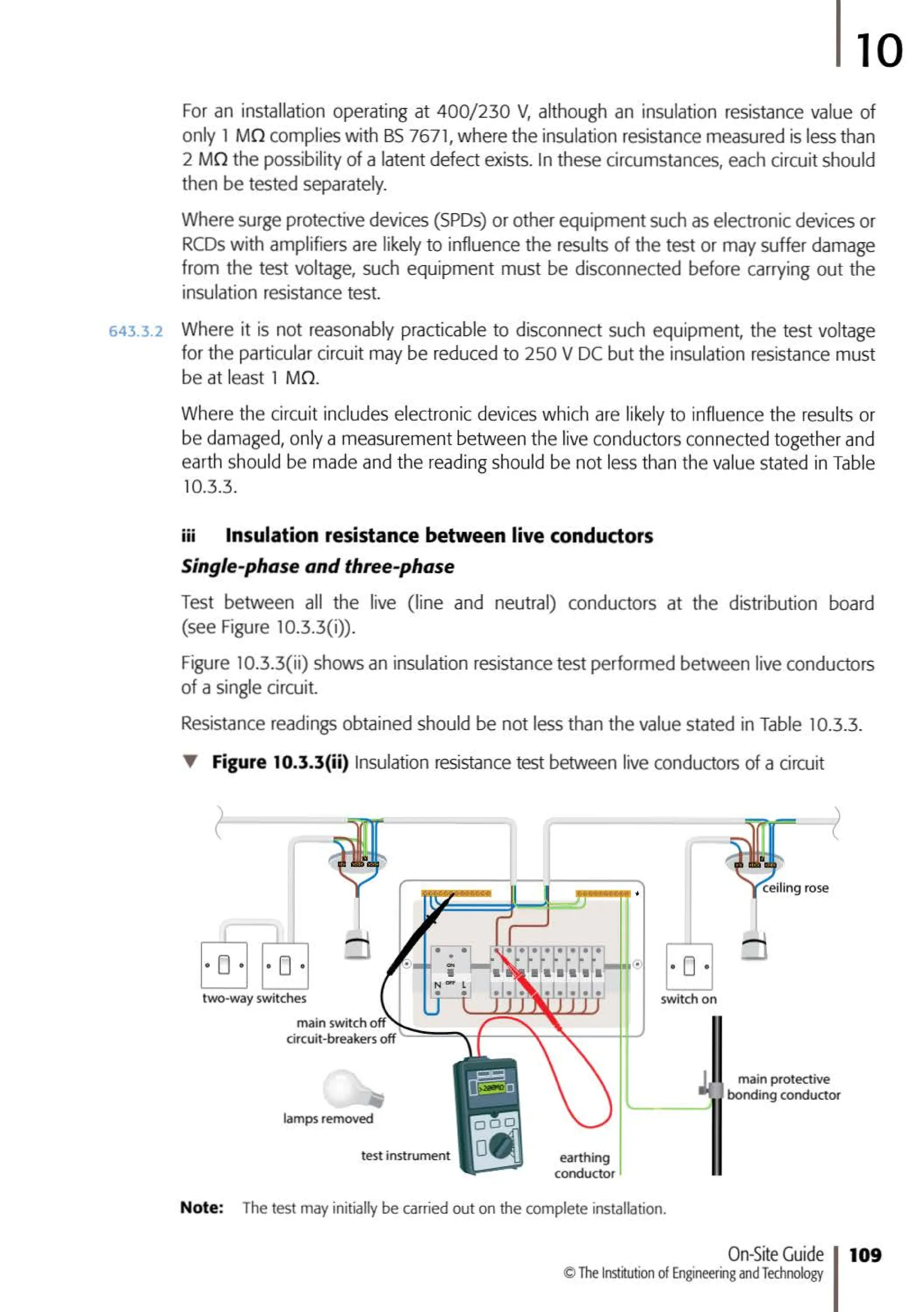
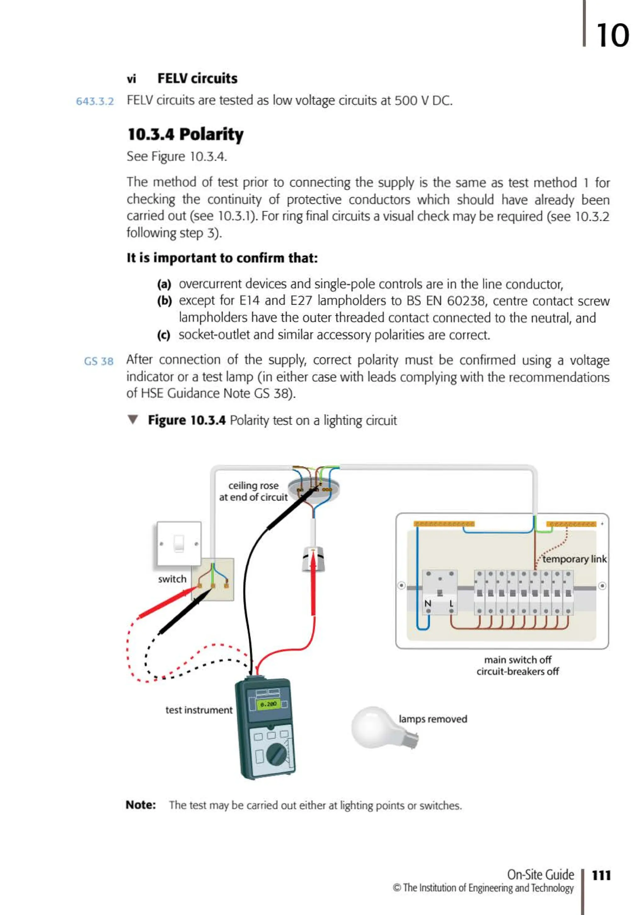
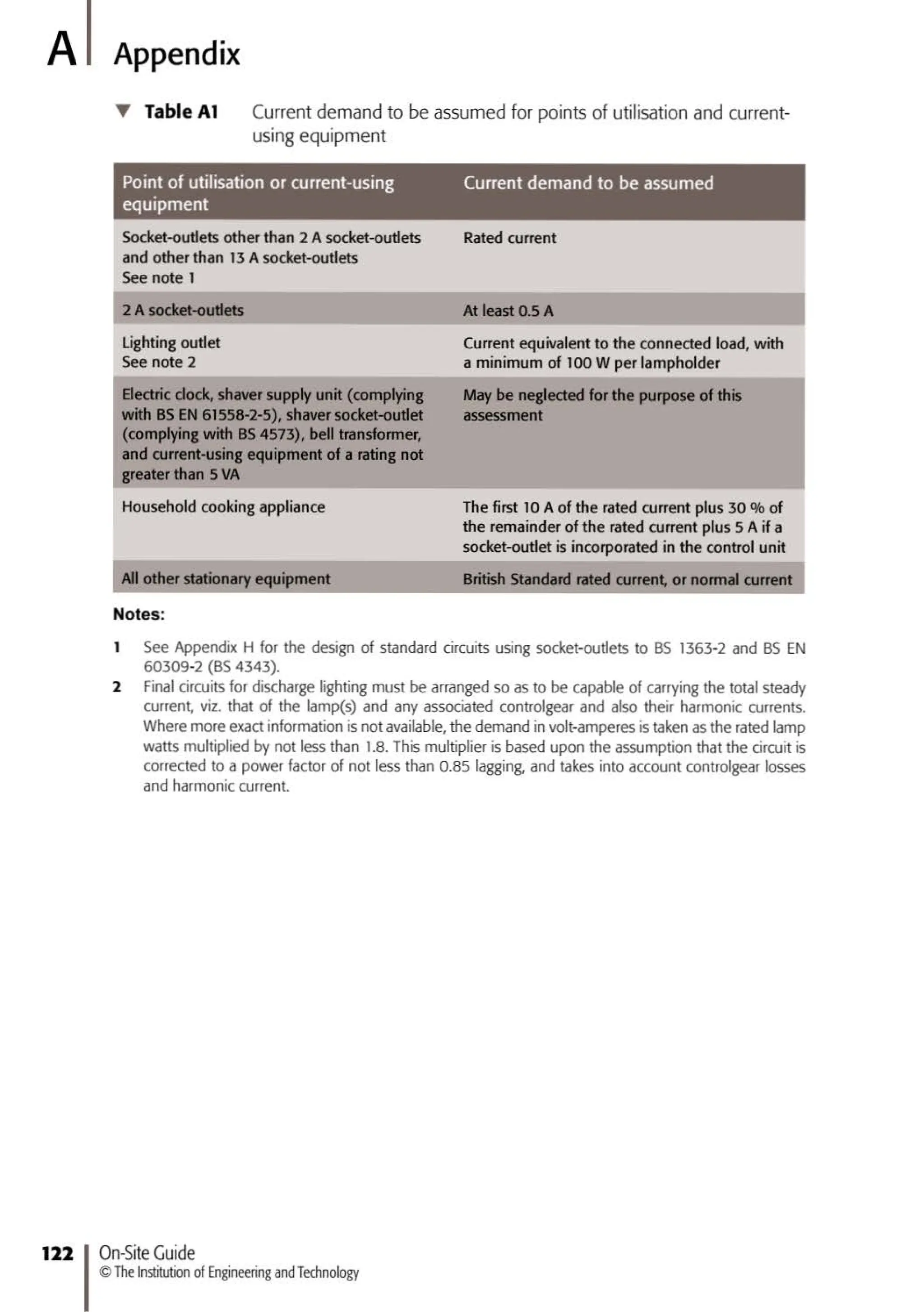
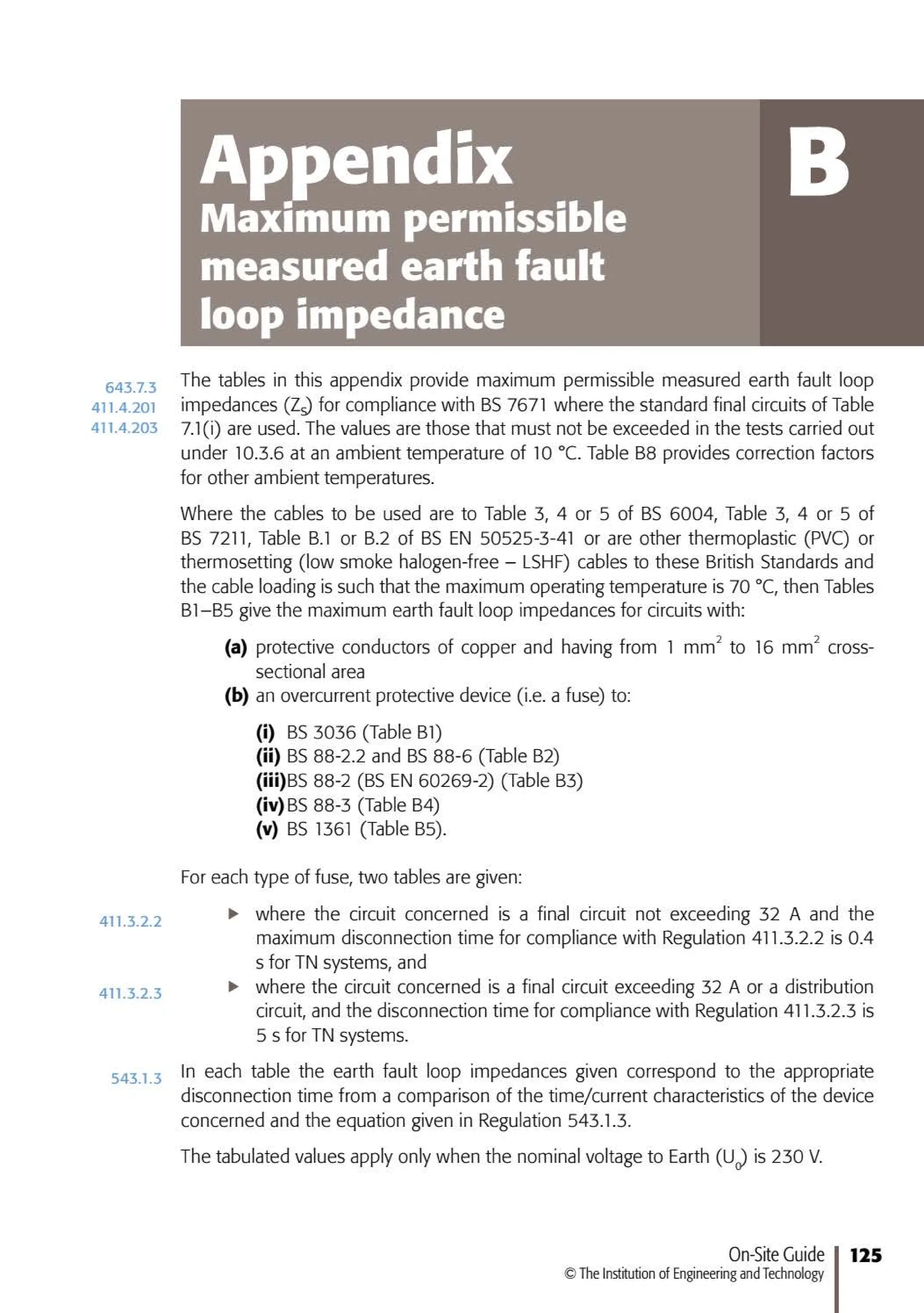
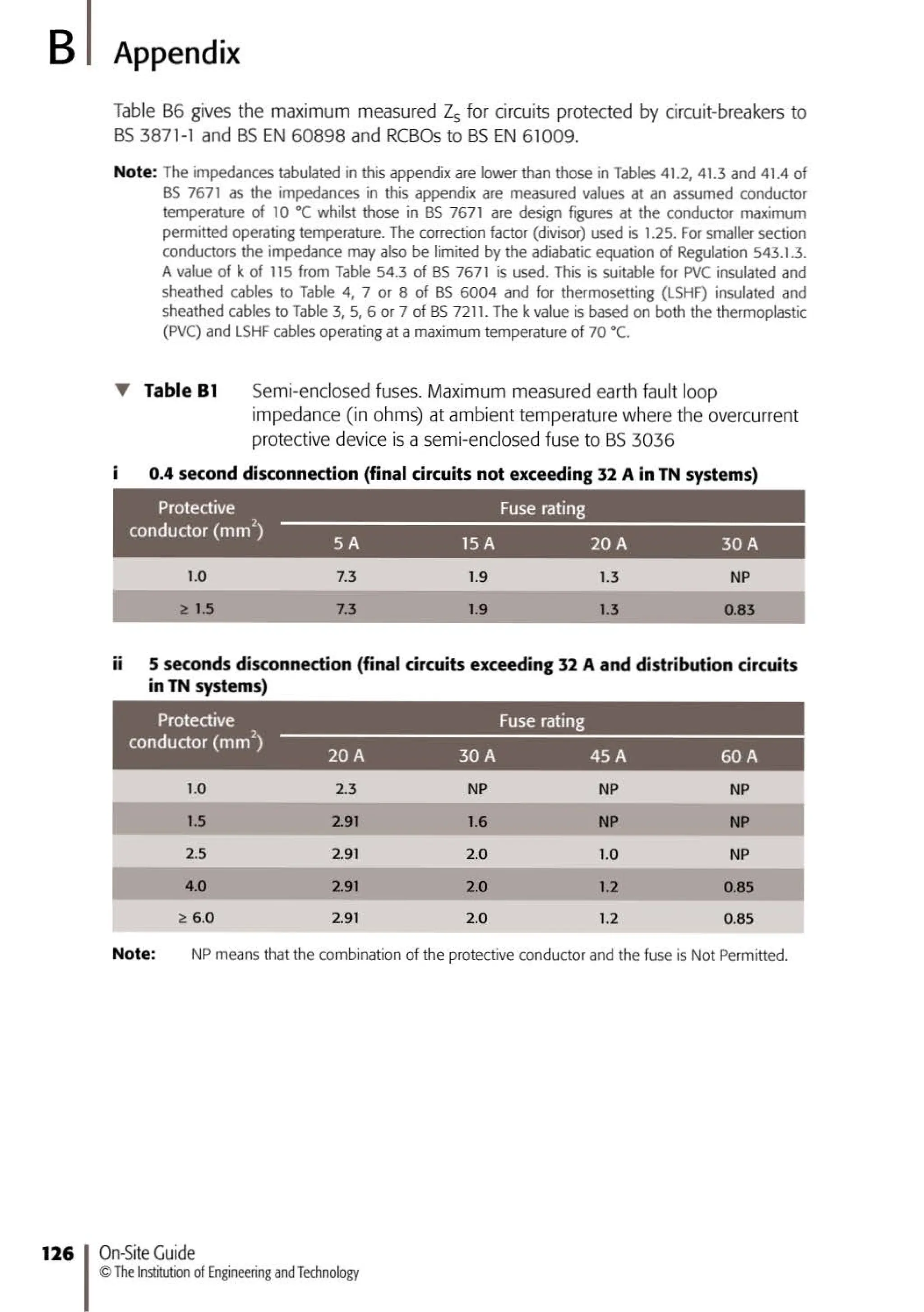
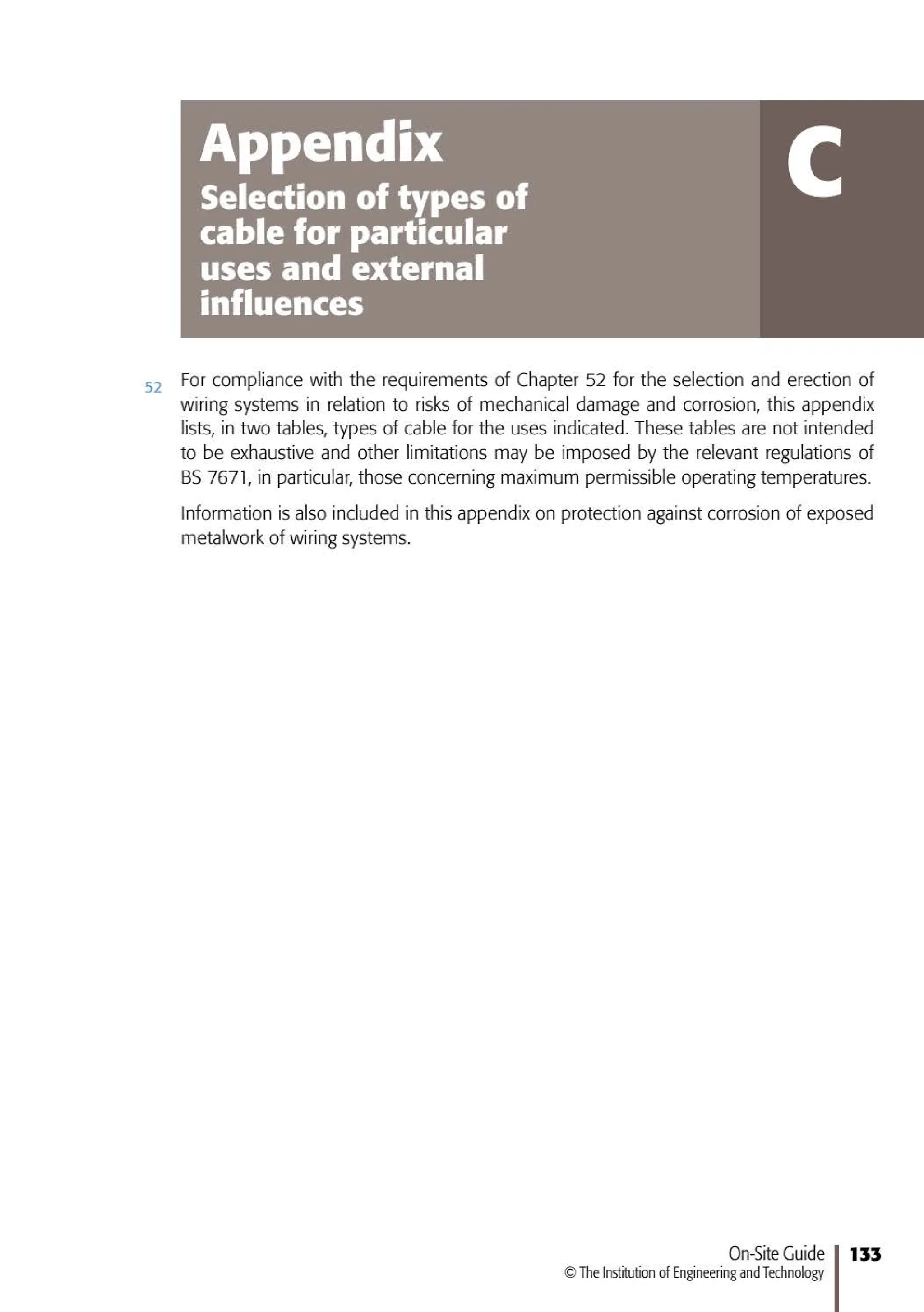
This document is the seventh edition of the IET Wiring Regulations (BS 7671), which is the national standard for electrical installation work in the UK. The document provides regulations and guidance for electrical installation design, inspection, and testing. It covers topics such as protective measures, earthing and bonding, cable selection and support, operation of residual current devices (RCDs), and more. The IET publishes updated editions of the Wiring Regulations to incorporate new information and changes to legislation.


![@
:;I
"'
:::>
~
::::0.'
c:
c:t.
0
:::>
a
g'
<><>.
:::>
r:::
~
~0
"' :::J
5.0-l
;;t rtf
n
::r Cl
~ c:
co.:
~ro
-
.,.
-
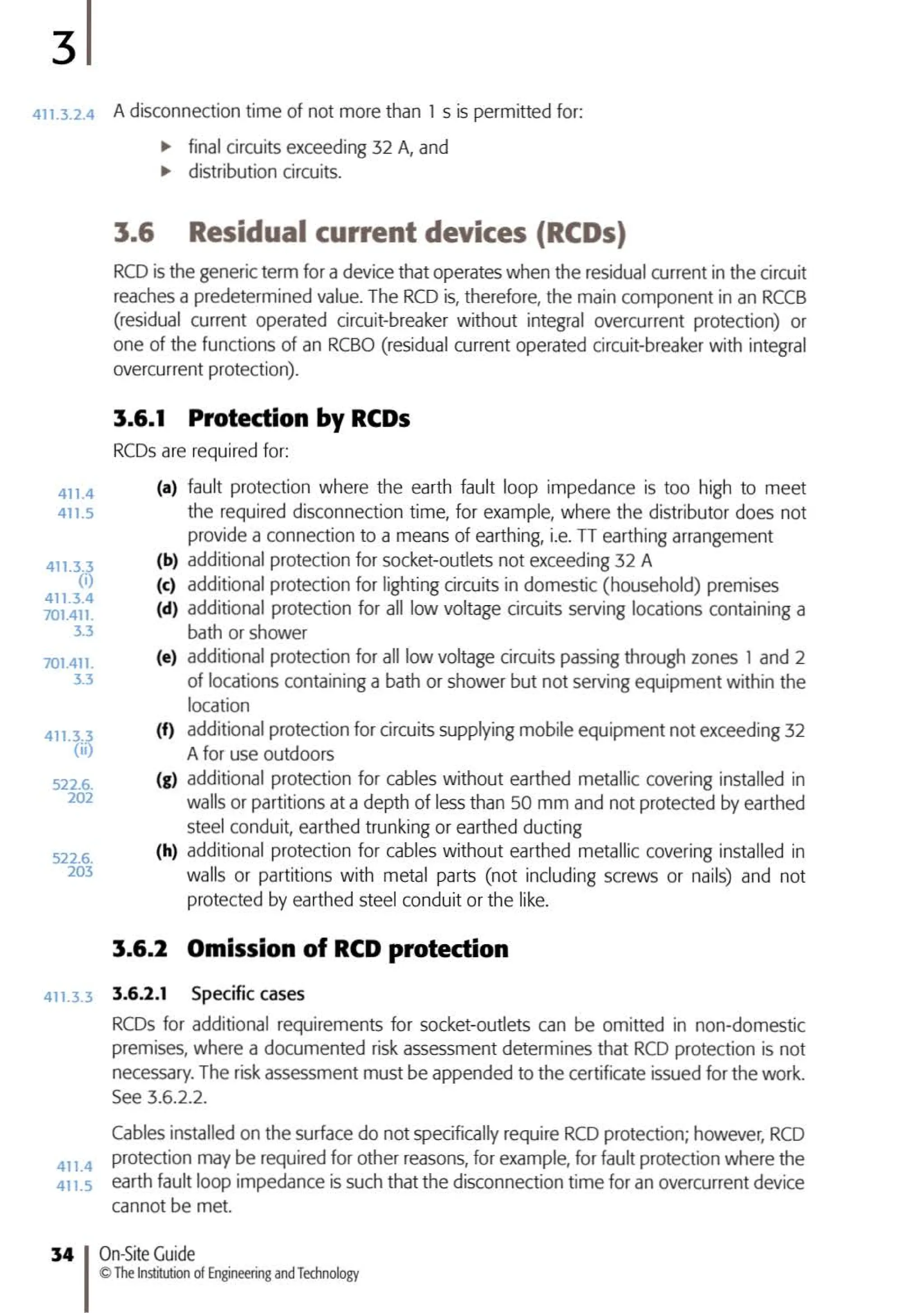
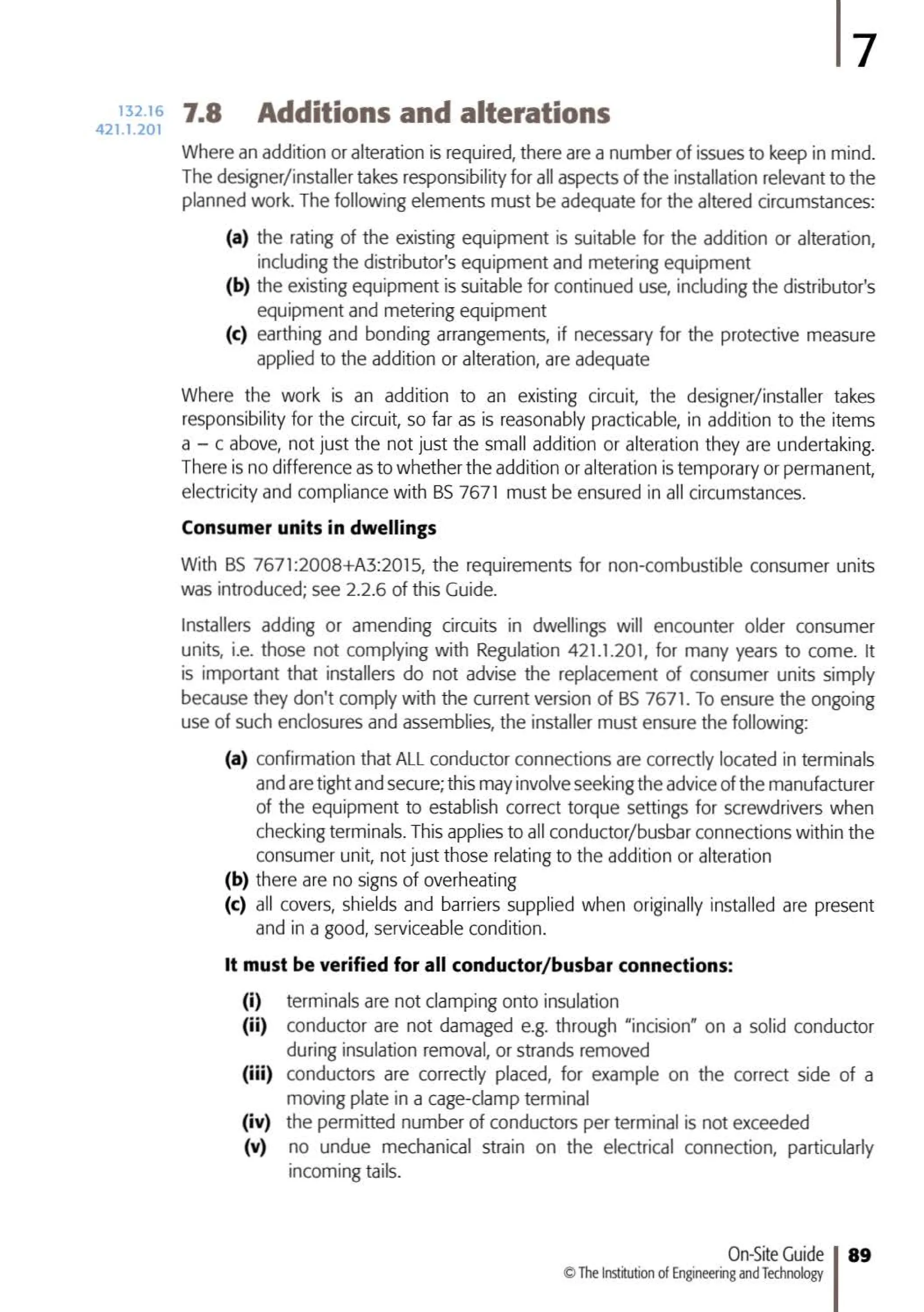
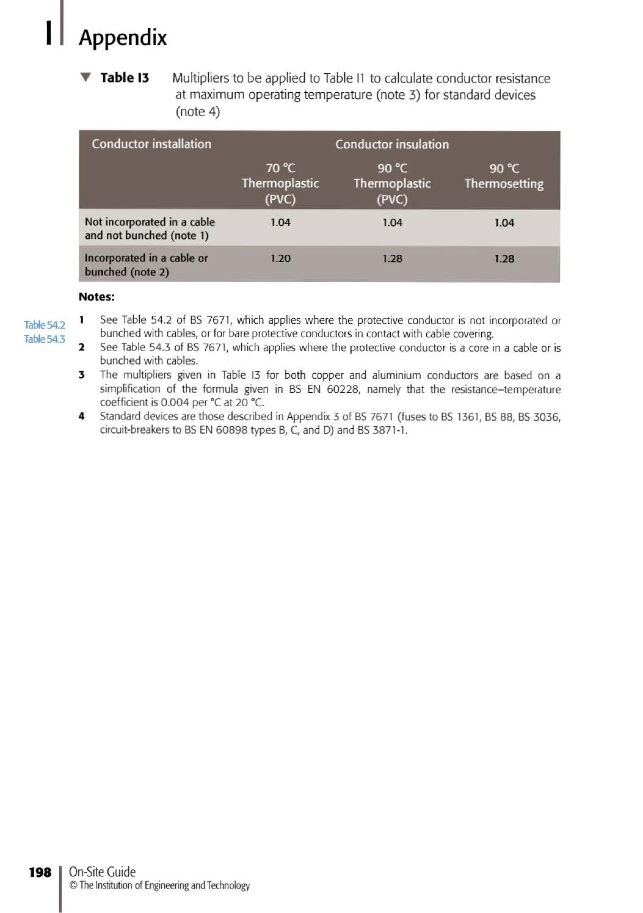
T Table 86 Circuit-breakers. Maximum measured earth fault loop impedance (in ohms) at ambient temperature where the overcurrent
device is a circuit-breaker to BS 3871 orBS EN 60898 or RCBO to BS EN 61009
0.1 to 5 second disconnection times
1
2
-
B
-
3&C
14.56 8.74
8.4 5.0
11.65 7.0
5.82 3.49
7.28
4.2
5.87
2.91
4.4 2.93 2.76 2.2 1.76 1.47 1.38 1.1 0.98 0.88 0.7 0.44
2.5 1.67 1.58 1.25 1.0 0.83 0.79 0.63 0.56 0.5 0.4 0.2
~
3.5 2.3 2.2 1.75 1.4 1.17 1.1 0.88 0.78 0.7 0.56 0.35
1.75 1.16 1.09 0.87 0.7 0.58 0.55 0.44 0.38 0.35 0.27 0.17
Circuit-breakers. Maximum measured earth fault loop impedance (in ohms) at ambient temperature where the overcurrent device is a
circuit-breaker to BS EN 60898 t e D or RCBO to BS EN 61009 t e D
Circuit-breaker
type
D 0.4 sec
05 sec
r:l
1.46
2.91
iii]
0.87
1.75
ml
0.55
1.09
mJ
0.44
0.87
Circuit-breaker rating (amperes)
li'lil
0.35
0.7
~
0.28
0.55
Hi] liD] ~
0.44 0.35 0.28 0.17
Regulation 434.5.2 of BS 7671:2018 requires that the protective conductor csa meets the requirements of BS EN 60898-1, -2 or
BS EN 61009-1, or the minimum quoted by the manufacturer. The sizes given in Table 87 are for energy limiting class 3, Types Band Cdevices
only.
)>
""0
""0
(I)
::s
c..
-·
><
OJ](https://image.slidesharecdn.com/on-siteguidebs76712018electricalregulationspdfdrive-240102212345-20c7c62c/75/On-Site-Guide-BS-7671_2018-Electrical-Regulations-PDFDrive-pdf-132-2048.jpg)


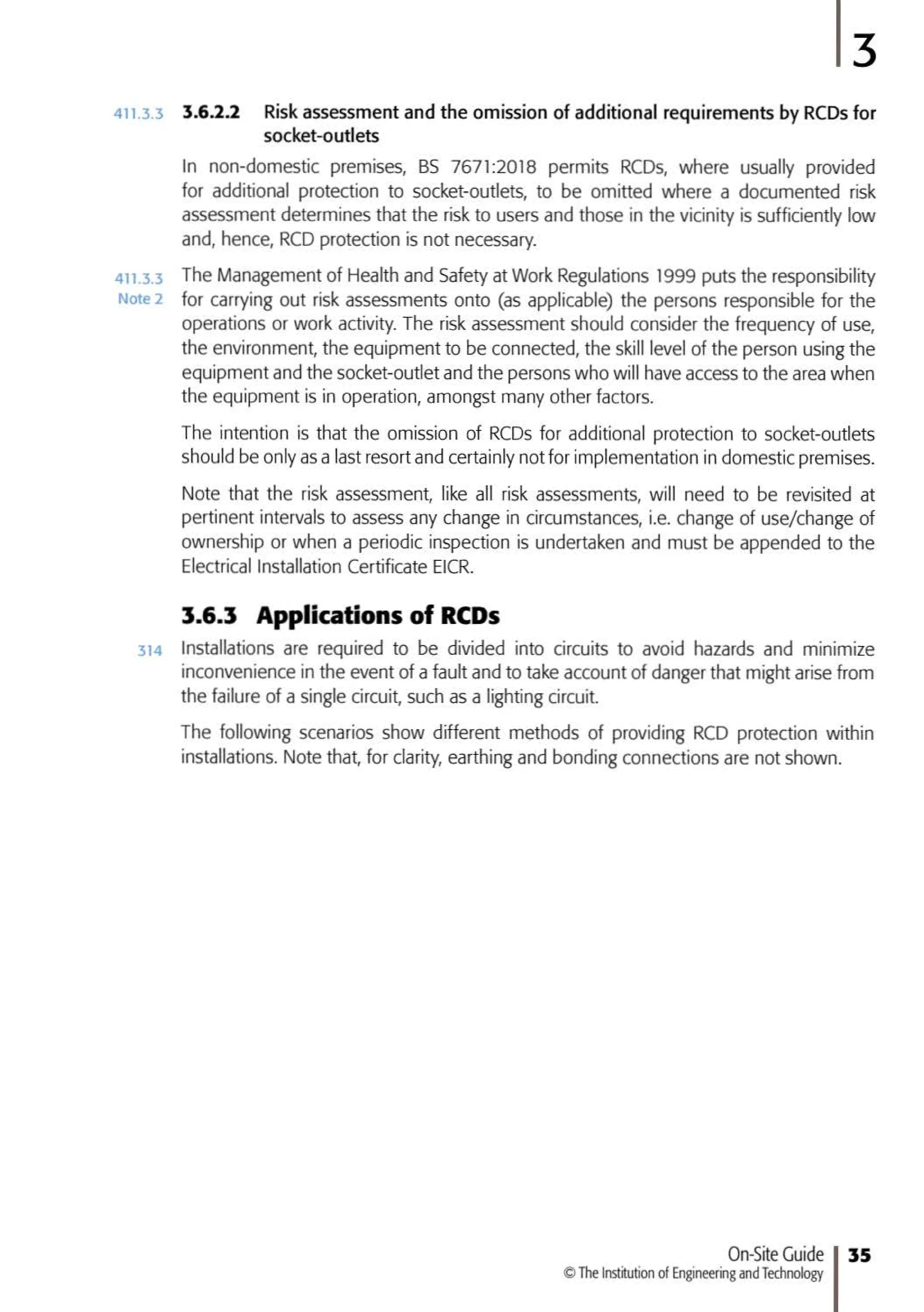
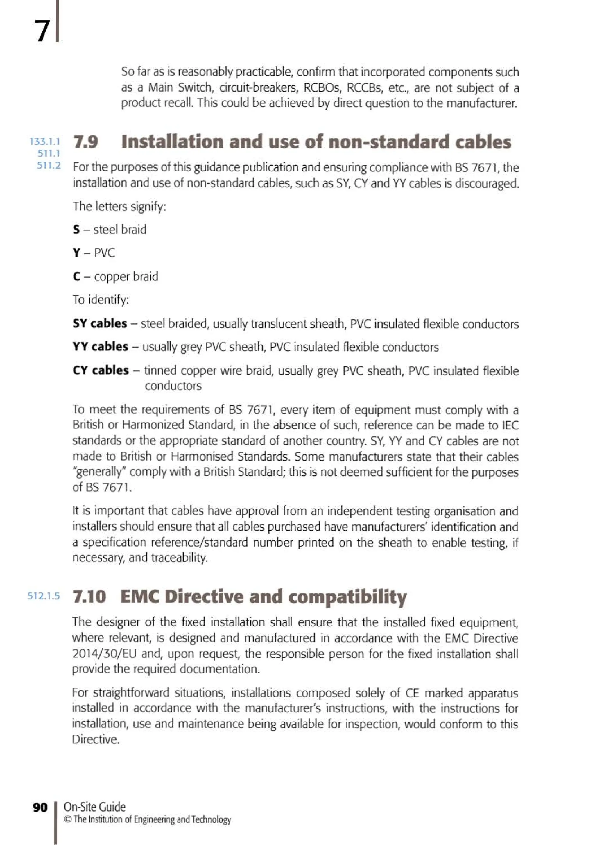
![Symbols
A Sc..::o.a-outlt"': mlntellJdtllg
Wl".ltrument Ot
~
,.,.., f(hed e11ergy meter
s.::xlo.et-out et • ~unctcn
W'l • WJt1 l'lour
d' S'• !ch VArh •Volt
Jl' 2 way 5Wtch,
ampt>r~ re;Jctlle
hour
single pole
X lnterrneodll!te ~ Mo!Of SIJI!• r,
SWllCh ~'I)L•fdl !>'yTnbol
Pull S..'1tch, IX] C,taH1clt.l
eft s•ngle·pole ~.l .lll!._'f
........... HuoH
"S(.:ent
~
fuse,
lum na.re rated curft'nl
lllJOl~
X
tmt T,SMCV
ltrtng 9 Opfl'fatlng
lurl na re (or rl"""e (cool)
-;,~(1.11 (i!"C:Ui!)
SeH<Dntalned
~
•.1.tlte (l")rwtKt,.
~
r11 ·m~t!y :;>en
e-rn~
--st ~1118
r!• air. l31tat..
,J"l nan
.,...,.!'ydosed
@ Pd>httln
I Morualv
~....!- llld!::""~
~-""i .,etared"""""
o~:>
e)c.:x• 6. Tive<-phas<o
.......q. Jclt.l
lfr
Al:,)L:ll(.
...gr.d :.ngdevice y r~
g{'f -..o-,a symbol ......one..w
(OJ!. bell)
-0-=notU5ed
11' Ruzw
on IEC~rds
'i:Y Telephone
han&~ ~ Rect1her
0 M~< rcphone (%1 r.ven.cr
c(J Le>udspeakef -tJ- BMk"V ol
pnrnary or
'r Antenna st..:ot'ldluy cclls
$
0 Mach•ne lr.m..,form~·t
• F'unaion ~·nt•ral ':.yrnbol
M MOIOt' w1
th two wu"':i ngs
C = Cenef(l!Or
@] StJIIC getl(•f,ttOI 10' t •l!o' c.
0 /<>~mete<
10 n~J M
10' lulo k
@ Armleter
10
"'" "'
10 n1:10 u
SGT 2AY
Ttie only guiile to BS 7671 written l>y the Wiring
Regulations experts at the lET, ttie On-Site Guide
contains clear, concise guidance to ttie technical
information contained in the Regulations:
ISBN 978-1-78561-442- 2
9](https://image.slidesharecdn.com/on-siteguidebs76712018electricalregulationspdfdrive-240102212345-20c7c62c/75/On-Site-Guide-BS-7671_2018-Electrical-Regulations-PDFDrive-pdf-218-2048.jpg)


