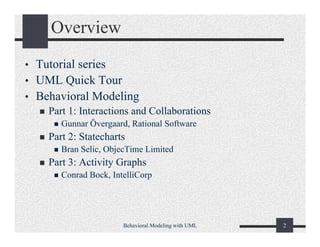
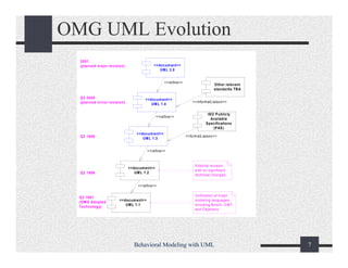
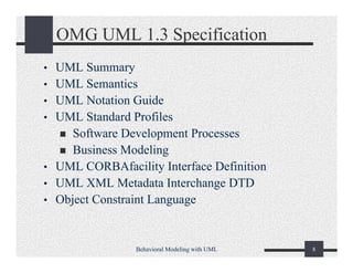
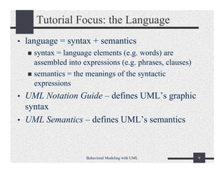
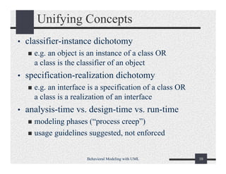
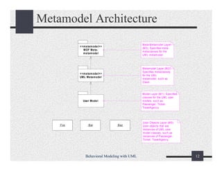
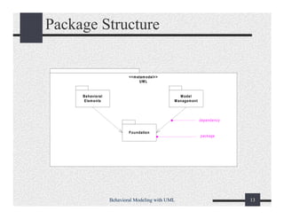
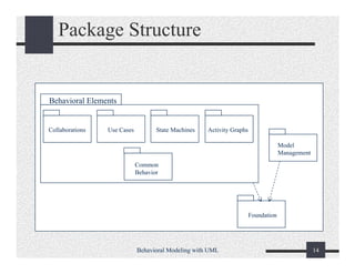
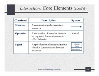
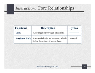
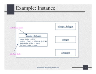
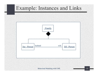
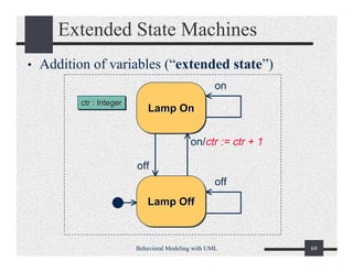
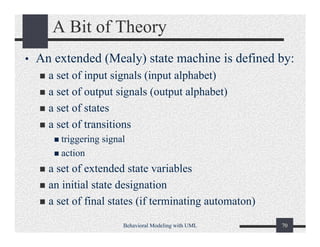
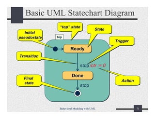
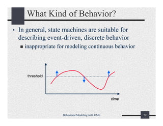
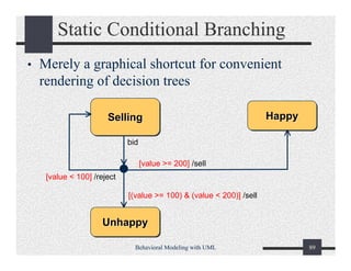
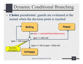
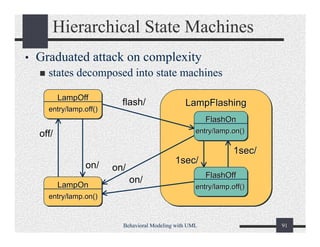
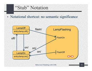
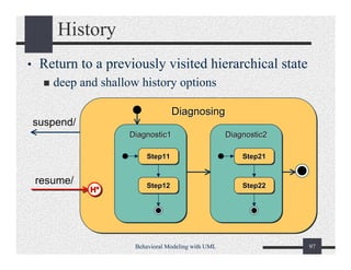
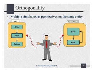
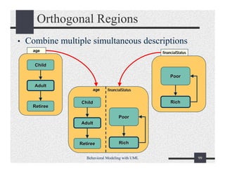
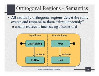
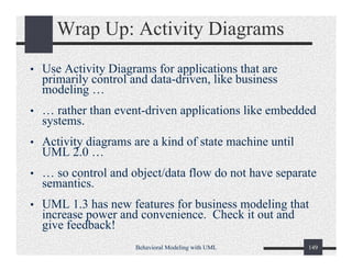
This document provides an overview of a tutorial on behavioral modeling with the Unified Modeling Language (UML). The tutorial will cover three parts: interactions and collaborations, statecharts, and activity graphs. It discusses the goals of the tutorial, which are to explain what UML is and how to model large, complex systems using UML's basic constructs and diagramming techniques in an implementation-independent manner. The document also provides background information on UML, including its evolution, specification, language architecture involving its metamodel, and package structure.
UML (Unified Modeling Language) is a standard modeling language used to visualize, specify, construct, and document software systems. It uses graphical notation to depict systems from initial design through detailed design. Common UML diagram types include use case diagrams, class diagrams, sequence diagrams, activity diagrams, and state machine diagrams. UML provides a standard way to communicate designs across development teams and is supported by many modeling tools.
The document discusses the Unified Modeling Language (UML) which is a general-purpose modeling language used to visualize, specify, construct, and document software systems. UML uses graphical notation to represent the design of software projects including concepts like use case diagrams, class diagrams, sequence diagrams, and more. It provides a standard way to visualize a system from different perspectives including structural and behavioral views.
Here are the key differences between objects and classes in UML:
- Classes define the general characteristics (attributes and operations) that objects of that class will have. Objects are specific instances of a class.
- Classes are static definitions, while objects are dynamic instances of classes that exist at run time.
- In class diagrams, classes are represented as boxes containing the attributes and operations. Objects are represented as boxes with the class name followed by a colon and the object name (e.g. Person:John).
- Classes define the common properties for a set of objects, while each object is a unique instance of a class with its own identity and particular values for attributes.
- Classes are abstractions,
UWE is a software engineering approach for developing web applications that uses UML for modeling. It includes a modeling language, metamodel, and process for developing web applications. The modeling language uses standard UML diagrams when possible, and extends UML with web-specific stereotypes when needed. UWE focuses on systematization and automatic code generation from models.
This document summarizes key aspects of system design for addressing concurrency. It discusses identifying threads of control from sequence diagrams and assigning inherently concurrent objects to different threads. Race conditions that can occur with concurrent threads are explained. Examples are provided to illustrate problems that can arise and how synchronization of threads can solve them. Questions for identifying concurrency in a system are outlined. Implementing concurrency using physical or logical threads is described. Deployment and component diagrams for modeling hardware/software mapping and dependencies between system components are introduced.
The document discusses the importance of communication in software engineering projects. It describes an example where two missile electrical boxes were joined with reversed wires, which could have caused a crash. Effective communication is needed to organize large projects and avoid such issues. Project organization involves defining work products, schedules, participants, tasks, and using tools like project management software. Roles can include management, development, cross-functional, and consultants. Tasks produce work products and schedules map tasks over time using techniques like Gantt and PERT charts.
The document describes the objectives and requirements for ARENA, a generic infrastructure to support online multiplayer gaming communities. ARENA aims to provide a centralized system to register games, players, organize tournaments and track scores. This will eliminate redundancy across individual game systems. The system must support 10 concurrent tournaments with hundreds of players and spectators. Initial models of ARENA include subsystem decompositions, use case and object models. More details on ARENA can be found on the provided website and case study descriptions in the textbook.
1. Object modeling is a key activity in analysis that involves identifying important classes, attributes, methods, and associations from use cases and domain knowledge.
2. Class identification can be done through syntactic analysis of use cases using techniques like Abbott's method of mapping parts of speech to model elements.
3. Different roles like analysts, designers, and implementors have varying needs from class diagrams depending on the development phase and tasks. The level of detail needed increases from analysis to implementation.
The document discusses design patterns and how they can be used to simplify complex object models. It introduces the composite, adapter, bridge, and facade patterns. The composite pattern models tree structures and allows components to be treated uniformly. The adapter pattern allows classes with incompatible interfaces to work together. The bridge pattern decouples an abstraction from its implementation. The facade pattern provides a simplified interface to a subsystem. Design patterns use inheritance and delegation to provide flexible, reusable solutions to common programming problems.
This document discusses several design patterns including the Proxy, Command, Observer, Strategy, Abstract Factory patterns. For each pattern, it provides examples of problems they can solve, their structure using UML diagrams, and how they work to decouple classes and support extensibility. It also discusses how clues in non-functional requirements can indicate when certain design patterns may be applicable.
The document discusses object design and how it builds upon requirements analysis. It describes how object design adds details like visibility, type signatures, and contracts to specify interfaces more precisely. It also discusses different roles in object design like class implementors, users, and extenders and how they interact. Information hiding principles and tradeoffs between hiding and efficiency are covered. Formal specification of contracts through invariants, preconditions and postconditions is introduced.
The document discusses object design in software engineering. It describes object design as consisting of four main activities: reuse, interface specification, object model restructuring, and object model optimization. Reuse involves identifying existing solutions like inheritance, off-the-shelf components, and design patterns that can be leveraged. Interface specification describes each class interface precisely. Restructuring and optimization transform the object model to improve understandability, extensibility, and address performance. The document provides examples and details on each object design activity.
OCL is a formal language used to express constraints over UML models. It allows constraints to be written that cannot otherwise be expressed in diagrams. OCL expressions are evaluated in a specified context and return True or False. Constraints can be expressed involving a single class, directly related classes through associations, or indirectly related classes by navigating associations. Collections like sets, bags, and sequences are used extensively in OCL expressions.
The document discusses modeling software systems using the Unified Modeling Language (UML). It provides an overview of UML and describes some of the main diagram types used for modeling, including use case diagrams for describing functional requirements, class diagrams for describing system structure, and sequence diagrams for describing dynamic object interactions. The document emphasizes that UML provides a standard way to model systems at different levels of abstraction through multiple views and diagrams.
This chapter introduces software engineering and its objectives. It discusses dealing with complexity through abstraction, decomposition, and hierarchy. Models are used to provide different views of a system, such as functional, object, and dynamic models. Design patterns and frameworks help make software more reusable and reduce complexity. The software lifecycle encompasses activities like requirements, design, implementation, and testing to develop software.
The document provides information on Unified Modeling Language (UML) and its various diagrams used for modeling software systems. It discusses the background and benefits of object-oriented modeling. It then describes UML as a modeling language comprising various diagram types to capture different views of a system, including structural, behavioral, implementation and user views. Specific diagram types covered include use case diagrams, class diagrams, sequence diagrams, and object diagrams. Examples are provided for each diagram type to illustrate their elements and notation.
This document discusses system design and decomposing systems into subsystems. It makes three key points:
1) System design is difficult because the solution domain is changing rapidly and design knowledge has a short half-life of 3-5 years. This makes the design window challenging.
2) To bridge the gap between a problem and existing system, the document recommends using the "divide and conquer" approach of identifying major design goals and modeling the system as a set of subsystems that address these goals.
3) Good subsystem design principles include having high coherence (related classes) and low coupling (independence) between subsystems. This can be achieved by minimizing inter-subsystem interactions and calls and ensuring subsystems
UML object models can be mapped to relational databases by mapping classes to tables, attributes to columns, and associations as either buried foreign keys or separate tables. There are two approaches to mapping inheritance: using separate tables for each class or duplicating superclass columns in subclass tables. The tradeoff is between easier modification of the superclass versus faster queries.
The document discusses software testing, including definitions of key terms like failure, error, and fault. It covers different types of testing like unit testing, integration testing, and acceptance testing. It also discusses techniques for fault avoidance, detection, and tolerance. Black-box and white-box testing approaches are explained. Finally, it provides an overview of the JUnit testing framework in Java.
The document discusses the process of mapping object models to code. It describes four types of transformations: model transformation, forward engineering, reverse engineering, and refactoring. Model transformations optimize the object design model, such as collapsing objects or delaying expensive computations. Forward engineering implements the object design model in a programming language by mapping inheritance, associations, contracts, and object models to tables. The document provides examples of each type of transformation.
This document provides an introduction to structural and use case modeling using the Unified Modeling Language (UML). It defines structural modeling as emphasizing the structure of objects, including their classifiers, relationships, attributes and operations. Use case modeling partitions system functionality into meaningful transactions ("use cases") between users ("actors") and the system. The document then reviews the core concepts and diagram types for both structural and use case modeling in UML.
The document discusses the systems analysis and design process for developing systems like a Management Information System (MIS). It describes the key stages in the systems development life cycle, including problem recognition, feasibility study, systems analysis, design, testing, implementation, and maintenance. It provides details on various techniques and considerations used at each stage, such as classifying problem types during problem recognition, assessing technical, operational, and economic feasibility, gathering requirements, and designing system components. The iterative nature of systems development is also emphasized.
This document discusses dynamic modeling in object-oriented analysis. It covers:
- Dynamic models describe components with interesting dynamic behavior using state diagrams, sequence diagrams, and activity diagrams.
- Sequence diagrams show object interactions, and can identify potential classes and their operations.
- State diagrams model the dynamic behavior of individual classes through states and transitions triggered by events or activities.
- Activity diagrams can model complex business logic and workflows.
The document provides examples and best practices for constructing dynamic models during requirements analysis.
System Analysis and Design - Unified Modeling Language (UML)Dudy Ali
Dokumen tersebut membahas tentang Unified Modeling Language (UML) yang merupakan bahasa standar untuk membuat blueprint perancangan sistem perangkat lunak. Dokumen ini menjelaskan berbagai diagram UML seperti use case diagram, class diagram, sequence diagram, dan state machine diagram beserta penjelasan mengenai komponen-komponen pada masing-masing diagram.
The document discusses object modeling for software engineering projects. It covers modeling reality versus models, the types of objects (entity, boundary, control), and the order of activities in object modeling. The key activities in object modeling include identifying classes from use cases, flows of events, and other documentation. Class diagrams are then generated to represent the relationships between these classes.
The document discusses changes between UML 1.x and UML 2.0. It provides an overview of UML 2.0 including new diagram types like timing diagrams and changes to existing diagrams. Key changes noted are increased precision, modularity, and rationalization through removing redundant concepts. The document then covers specific diagram updates, including activity diagrams now able to model workflow and state machines able to model object state. Advanced class diagram relationships and interfaces are also reviewed.
UML (Unified Modeling Language) was created in the 1990s as a general-purpose modeling language for software engineering. It was developed by Grady Booch, James Rumbaugh, and Ivar Jacobson, known as "the three amigos". UML was later standardized by the Object Management Group and now includes diagrams for modeling software structure, behavior, and architecture. The OMG also established a certification program with three levels to ensure consistent understanding and proficiency with UML.
This document provides an introduction to structural and use case modeling with the Unified Modeling Language (UML). It outlines a tutorial series on UML that covers introduction, behavioral modeling, and advanced modeling. The document discusses why modeling is useful, provides an overview of UML's goals and evolution, and describes some of UML's foundational concepts including its building blocks, well-formedness rules, and unifying concepts.
The Unified Modeling Language (UML) is a family of graphical notations used to describe and design software systems. UML was created in the 1990s to standardize modeling languages for object-oriented systems. It is maintained by the Object Management Group and includes diagram types like class, sequence, activity, and state diagrams. UML can be used for conceptual modeling, software design, code generation, and other applications throughout the software development lifecycle.
The document discusses OMG model transformation standards being implemented in Eclipse, including QVT Relations and MTL. It describes Obeo's work on these projects, challenges around standardization and interoperability, and ambiguities in the OMG specifications being addressed.
OMG Specifications for Enterprise InteroperabilityBrian Elvesæter
B. Elvesæter and A.-J. Berre, "OMG Specifications for Enterprise Interoperability", paper presentation at IESA 2010 Workshop “Standards - a foundation for Interoperability”, Coventry, United Kingdom, 13 April 2010.
Light Maturity Models (LMM): An Agile ApplicationLuigi Buglione
This presentation shows an easier possible way for starting the aplication of maturity models (light), coming back to the original Crosby\'s idea. It presents some possible ways to apply LMM to Agile projects/organizations
This document provides an overview of the history and development of the Unified Modeling Language (UML) and Foundational UML (fUML) standard for executable modeling. It discusses how UML evolved from its origins in object-oriented analysis and design in the 1980s-1990s to add formal execution semantics definitions. fUML and the Action Language for Foundational UML (Alf) provide a computationally complete subset of UML with a defined execution model, addressing UML's previous lack of precise semantics. The document outlines the key components and implementations of fUML and Alf and their role in specifying UML's structural and behavioral semantics formally.
Action Languages for UML execution: Where we are and where we are headingFederico Ciccozzi
Invited talk on action languages for UML at the international workshop on Action Languages and Precise Modeling for Cyber-Physical Systems Design and Testing at CASCON 2016
This document provides 3 examples of XML applications:
1. Chemical Markup Language (CML) is used to organize complex chemical data like molecular structures in an easy-to-search format.
2. Mathematical Markup Language (MathML) allows mathematical equations to be displayed on web pages.
3. Synchronized Multimedia Integration Language (SMIL) synchronizes multimedia elements like video, audio, and text for presentations on the web.
When talking about modeling, I think there will be a bundle of terms that will come to our mind, UML, domain driven development, DSL, forward/reverse enginerring, MDD, MDA, BPMN. These technology or methodology have been there for years; And obviously, modeling has proven itself to provide value by improving communication, business-alignment, quality, and productivity. Its applicability includes a number of disciplines such as analysis, design, or development. But why aren’t we all doing Model Driven Development yet?
The document discusses Object Oriented Analysis and Design (OOAD) using the Unified Modeling Language (UML). It provides an introduction to the UML, explaining that it was created to provide a common language for software engineering. The UML can be used within various development processes, such as the waterfall model, spiral model, iterative frameworks, and Rational Unified Process. The document then covers object orientation concepts, an overview of UML diagrams, and how UML can be applied during analysis and design phases of the software development lifecycle.
The Unified Modeling Language (UML) has arguably succeeded in becoming the most commonly used modeling notation for software development. But “modeling” in the software community seems largely to mean simply drawing pictures, either to represent the problem domain or to blueprint a solution, without a precise enough meaning to fully specify the functionality of the system being developed. As a result, the UML standard,S up to and including UML 2.4.1, do not define the semantics of UML models at all precisely.
Nevertheless, there has also long been an interest in models that are more precise, even to the extent that they may be executed in their own right. It has taken a while for this viewpoint to penetrate into the mainstream of UML usage. But there has been in a great deal of work in recent years toward the standardization of the formal semantics of UML models – the “meaning” behind the pictures: the Foundational UML (fUML) specification adopted in 2008; the Action Language for fUML (Alf), adopted in 2010; the UML 2.5 specification (which includes a semantics conformance point for the first time); and the Precise Semantics of UML Composite Structures.
This presentation reviews the state of this work and the implications in practice of bringing real meaning to UML.
This document provides an introduction and overview of structural modeling and use case modeling in the Unified Modeling Language (UML). It discusses the goals and benefits of modeling, provides a quick tour of UML concepts, and covers the core elements of structural modeling like classes, interfaces, associations and diagrams. It explains when and how to model system structure and provides an example of interface-based design. The document is intended to teach the basics of UML structural and use case modeling.
This is a one day workshop presentation, primarily on the new OMG Foundational UML specification for executable model semantics, but also discussing extensions for executable SysML (System Modeling Language) models.
The document is a slide presentation on UML modeling and profiling from a software engineering course. It introduces UML and the concepts of metamodeling. It explains that UML is used to specify, visualize, construct and document software system artifacts. The presentation then outlines the typical steps in UML modeling: 1) modeling use cases, 2) modeling system structure with classes and components, and 3) modeling deployment to hardware nodes.
The document discusses XML Metadata Interchange (XMI) which uses XML to transfer metadata and model information between tools and repositories. XMI allows the interchange of any metadata based on the Meta-Object Facility (MOF) standard, including UML models and the Common Warehouse Metamodel (CWM). It defines XML document type definitions (DTDs) for validating metadata streams.
The document discusses UML with action semantics (xUML), which allows UML models to be executed. It covers key concepts like actions, which are the fundamental unit of computational behavior, and action semantics, which remove assumptions about specific computing environments. xUML models can be used to define executable analysis models. The document also provides an overview of behavioral modeling elements in UML like use cases, and covers the action metamodel which defines how actions work through inputs, outputs, data flow, and control flow. It distinguishes between primitive actions and procedures as an action container.
Programming in UML: An Introduction to fUML 1.3 and Alf 1.1Ed Seidewitz
Based on a tutorial presentation given at the OMG Executable UML Information Day, this version of the presentation has been updated for fUML 1.3 and Alf 1.1, the latest versions as of this upload.
IRJET- American Sign Language ClassificationIRJET Journal
This document describes a system for classifying American Sign Language (ASL) gestures into their corresponding English alphabet letters and then converting those letters to audio using text-to-speech. The system uses convolutional neural networks (CNNs) with transfer learning using the VGG16 model to classify ASL images. It achieved 0.99 precision on classification. The CNN model was trained on a dataset of ASL alphabet gestures. Once a gesture is classified, the letter is converted to audio using the gTTS library to play the sound of the classified letter. The system provides a pipeline from image classification to audio output to help facilitate communication between deaf and hearing communities.
Similar to Object Modeling with UML: Behavioral Modeling (20)
ClojureScript allows developers to use the Clojure programming language to build applications that compile to JavaScript. This enables Clojure code to run in environments where JavaScript is supported, like web browsers and mobile apps. ClojureScript leverages the Google Closure compiler and library to provide whole program optimization of Clojure code compiling to JavaScript.
Why you should be excited about ClojureScriptelliando dias
ClojureScript allows Clojure code to compile to JavaScript. Created by Rich Hickey and friends, it provides optimizations for performance while maintaining readability and abstraction. As a Lisp for JavaScript, ClojureScript controls complexity on the web and benefits from JavaScript's status as a compilation target for many languages.
Functional Programming with Immutable Data Structureselliando dias
1. The document discusses the advantages of functional programming with immutable data structures for multi-threaded environments. It argues that shared mutable data and variables are fundamentally flawed concepts that can lead to bugs, while immutable data avoids these issues.
2. It presents Clojure as a functional programming language that uses immutable persistent data structures and software transactional memory to allow for safe, lock-free concurrency. This approach allows readers and writers to operate concurrently without blocking each other.
3. The document makes the case that Lisp parentheses in function calls uniquely define the tree structure of computations and enable powerful macro systems, homoiconicity, and structural editing of code.
O documento lista e descreve as principais partes de um contêiner de carga seco, incluindo o painel frontal, laterais, traseira, teto, piso e estrutura inferior. Muitos componentes como painéis laterais, travessas do teto e fundo são numerados de acordo com sua localização. As portas traseiras contêm quadros, painéis, dobradiças e barras de fechamento.
O documento discute a história da geometria projetiva, desde Euclides até seu uso em computação gráfica. Aborda figuras-chave como Pascal, que foi pioneiro na área, e como a perspectiva foi aplicada nas artes ao longo dos séculos.
Polyglot and Poly-paradigm Programming for Better Agilityelliando dias
This document discusses the benefits of polyglot and poly-paradigm programming approaches for building more agile applications. It describes how using multiple languages and programming paradigms can optimize both performance and developer productivity. Specifically, it suggests that statically-typed compiled languages be used for core application components while dynamically-typed scripting languages connect and customize these components. This approach allows optimizing areas that require speed/efficiency separately from those requiring flexibility. The document also advocates aspects and functional programming to address cross-cutting concerns and concurrency challenges that arise in modern applications.
This document discusses JavaScript libraries and frameworks. It provides an overview of some popular options like jQuery, Prototype, Dojo, MooTools, and YUI. It explains why developers use libraries, such as for faster development, cross-browser compatibility, and animation capabilities. The document also discusses how libraries resemble CSS and use selector syntax. Basic examples are provided to demonstrate common tasks like hover effects and row striping. Factors for choosing a library are outlined like maturity, documentation, community, and licensing. The document concludes by explaining how to obtain library code from project websites or Google's AJAX Libraries API.
How to Make an Eight Bit Computer and Save the World!elliando dias
This document summarizes a talk given to introduce an open source 8-bit computer project called the Humane Reader. The talk outlines the goals of providing a cheap e-book reader and computing platform using open source tools. It describes the hardware design which uses an AVR microcontroller and interfaces like video output, SD card, and USB. The talk also covers using open source tools for development and sourcing low-cost fabrication and assembly. The overall goals are to create an inexpensive device that can provide educational resources in developing areas.
Ragel is a parser generator that compiles to various host languages including Ruby. It is useful for parsing protocols and data formats and provides faster parsing than regular expressions or full LALR parsers. Several Ruby projects like Mongrel and Hpricot use Ragel for tasks like HTTP request parsing and HTML parsing. When using Ragel with Ruby, it can be compiled to Ruby code directly, which is slow, or a C extension can be written for better performance. The C extension extracts the parsed data from Ragel and makes it available to Ruby.
A Practical Guide to Connecting Hardware to the Webelliando dias
This document provides an overview of connecting hardware devices to the web using the Arduino platform. It discusses trends in electronics and computing that make this easier, describes the Arduino hardware and software, and covers various connection methods including directly to a computer, via wireless modems, Ethernet shields, and services like Pachube that allow sharing sensor data over the internet. The document aims to demonstrate how Arduinos can communicate with other devices and be used to build interactive systems.
O documento introduz o Arduino, uma plataforma de desenvolvimento open-source. Discute as características e componentes do Arduino, incluindo microcontroladores, software e exemplos de código. Também fornece instruções básicas sobre como programar o Arduino usando linguagem C.
O documento apresenta um mini-curso introdutório sobre Arduino, abordando o que é a plataforma Arduino, como é estruturado seu hardware, como programá-lo, exemplos básicos de código e aplicações possíveis como controle residencial e robótica.
The document discusses various functions for working with datasets in the Incanter library for Clojure. It describes how to create, read, save, select rows and columns from, and sort datasets. Functions are presented for building datasets from sequences, reading datasets from files and URLs, saving datasets to files and databases, selecting single or multiple columns, and filtering rows based on conditions. The document also provides an overview of the Incanter library and its various namespaces for statistics, charts, and other functionality.
Rango is a lightweight Ruby web framework built on Rack that aims to be more robust than Sinatra but smaller than Rails or Merb. It is inspired by Django and Merb, uses Ruby 1.9, and supports features like code reloading, Bundler, routing, rendering, and HTTP error handling. The documentation provides examples and details on using Rango.
Fab.in.a.box - Fab Academy: Machine Designelliando dias
This document describes the design of a multifab machine called MTM. It includes descriptions of the XY stage and Z axis drive mechanisms, as well as the tool heads and network used to control the machine. Key aspects of the design addressed include the stepper motor selection, drive electronics, motion control firmware, and use of a virtual machine environment and circular buffer to enable distributed control of the machine. Strengths of the design include low inertia enabling high acceleration, while weaknesses include low basic resolution and stiffness unsuitable for heavy milling.
The Digital Revolution: Machines that makeselliando dias
The document discusses the results of a study on the effects of a new drug on memory and cognitive function in older adults. The double-blind study involved giving either the new drug or a placebo to 100 volunteers aged 65-80 over a 6 month period. Testing showed those receiving the drug experienced statistically significant improvements in short-term memory retention and processing speed compared to the placebo group.
The document discusses using Clojure for Hadoop programming. Clojure is a dynamic functional programming language that runs on the Java Virtual Machine. The document provides an overview of Clojure and how its features like immutability and concurrency make it well-suited for Hadoop. It then shows examples of implementing Hadoop MapReduce jobs using Clojure by defining mapper and reducer functions.
This document provides an overview of Hadoop, including:
1) Hadoop solves the problems of analyzing massively large datasets by distributing data storage and analysis across multiple machines to tolerate node failure.
2) Hadoop uses HDFS for distributed data storage, which shards massive files across data nodes with replication for fault tolerance, and MapReduce for distributed data analysis by sending code to the data.
3) The document demonstrates MapReduce concepts like map, reduce, and their composition with an example job.
Hadoop and Hive Development at Facebookelliando dias
Facebook generates large amounts of user data daily from activities like status updates, photo uploads, and shared content. This data is stored in Hadoop using Hive for analytics. Some key facts:
- Facebook adds 4TB of new compressed data daily to its Hadoop cluster.
- The cluster has 4800 cores and 5.5PB of storage across 12TB nodes.
- Hive is used for over 7500 jobs daily and by around 200 engineers/analysts monthly.
- Performance improvements to Hive include lazy deserialization, map-side aggregation, and joins.
Multi-core Parallelization in Clojure - a Case Studyelliando dias
The document describes a case study on using Clojure for multi-core parallelization of the K-means clustering algorithm. It provides background on parallel programming concepts, an introduction to Clojure, and details on how the authors implemented a parallel K-means algorithm in Clojure using agents and software transactional memory. They present results showing speedups from parallelization and accuracy comparable to R's implementation on both synthetic and real-world datasets.
Generating privacy-protected synthetic data using Secludy and MilvusZilliz
During this demo, the founders of Secludy will demonstrate how their system utilizes Milvus to store and manipulate embeddings for generating privacy-protected synthetic data. Their approach not only maintains the confidentiality of the original data but also enhances the utility and scalability of LLMs under privacy constraints. Attendees, including machine learning engineers, data scientists, and data managers, will witness first-hand how Secludy's integration with Milvus empowers organizations to harness the power of LLMs securely and efficiently.
UiPath Test Automation using UiPath Test Suite series, part 6DianaGray10
Welcome to UiPath Test Automation using UiPath Test Suite series part 6. In this session, we will cover Test Automation with generative AI and Open AI.
UiPath Test Automation with generative AI and Open AI webinar offers an in-depth exploration of leveraging cutting-edge technologies for test automation within the UiPath platform. Attendees will delve into the integration of generative AI, a test automation solution, with Open AI advanced natural language processing capabilities.
Throughout the session, participants will discover how this synergy empowers testers to automate repetitive tasks, enhance testing accuracy, and expedite the software testing life cycle. Topics covered include the seamless integration process, practical use cases, and the benefits of harnessing AI-driven automation for UiPath testing initiatives. By attending this webinar, testers, and automation professionals can gain valuable insights into harnessing the power of AI to optimize their test automation workflows within the UiPath ecosystem, ultimately driving efficiency and quality in software development processes.
What will you get from this session?
1. Insights into integrating generative AI.
2. Understanding how this integration enhances test automation within the UiPath platform
3. Practical demonstrations
4. Exploration of real-world use cases illustrating the benefits of AI-driven test automation for UiPath
Topics covered:
What is generative AI
Test Automation with generative AI and Open AI.
UiPath integration with generative AI
Speaker:
Deepak Rai, Automation Practice Lead, Boundaryless Group and UiPath MVP
For the full video of this presentation, please visit: https://www.edge-ai-vision.com/2024/06/building-and-scaling-ai-applications-with-the-nx-ai-manager-a-presentation-from-network-optix/
Robin van Emden, Senior Director of Data Science at Network Optix, presents the “Building and Scaling AI Applications with the Nx AI Manager,” tutorial at the May 2024 Embedded Vision Summit.
In this presentation, van Emden covers the basics of scaling edge AI solutions using the Nx tool kit. He emphasizes the process of developing AI models and deploying them globally. He also showcases the conversion of AI models and the creation of effective edge AI pipelines, with a focus on pre-processing, model conversion, selecting the appropriate inference engine for the target hardware and post-processing.
van Emden shows how Nx can simplify the developer’s life and facilitate a rapid transition from concept to production-ready applications.He provides valuable insights into developing scalable and efficient edge AI solutions, with a strong focus on practical implementation.
AI 101: An Introduction to the Basics and Impact of Artificial IntelligenceIndexBug
Imagine a world where machines not only perform tasks but also learn, adapt, and make decisions. This is the promise of Artificial Intelligence (AI), a technology that's not just enhancing our lives but revolutionizing entire industries.
CAKE: Sharing Slices of Confidential Data on BlockchainClaudio Di Ciccio
Presented at the CAiSE 2024 Forum, Intelligent Information Systems, June 6th, Limassol, Cyprus.
Synopsis: Cooperative information systems typically involve various entities in a collaborative process within a distributed environment. Blockchain technology offers a mechanism for automating such processes, even when only partial trust exists among participants. The data stored on the blockchain is replicated across all nodes in the network, ensuring accessibility to all participants. While this aspect facilitates traceability, integrity, and persistence, it poses challenges for adopting public blockchains in enterprise settings due to confidentiality issues. In this paper, we present a software tool named Control Access via Key Encryption (CAKE), designed to ensure data confidentiality in scenarios involving public blockchains. After outlining its core components and functionalities, we showcase the application of CAKE in the context of a real-world cyber-security project within the logistics domain.
Paper: https://doi.org/10.1007/978-3-031-61000-4_16
Programming Foundation Models with DSPy - Meetup SlidesZilliz
Prompting language models is hard, while programming language models is easy. In this talk, I will discuss the state-of-the-art framework DSPy for programming foundation models with its powerful optimizers and runtime constraint system.
TrustArc Webinar - 2024 Global Privacy SurveyTrustArc
How does your privacy program stack up against your peers? What challenges are privacy teams tackling and prioritizing in 2024?
In the fifth annual Global Privacy Benchmarks Survey, we asked over 1,800 global privacy professionals and business executives to share their perspectives on the current state of privacy inside and outside of their organizations. This year’s report focused on emerging areas of importance for privacy and compliance professionals, including considerations and implications of Artificial Intelligence (AI) technologies, building brand trust, and different approaches for achieving higher privacy competence scores.
See how organizational priorities and strategic approaches to data security and privacy are evolving around the globe.
This webinar will review:
- The top 10 privacy insights from the fifth annual Global Privacy Benchmarks Survey
- The top challenges for privacy leaders, practitioners, and organizations in 2024
- Key themes to consider in developing and maintaining your privacy program
Infrastructure Challenges in Scaling RAG with Custom AI modelsZilliz
Building Retrieval-Augmented Generation (RAG) systems with open-source and custom AI models is a complex task. This talk explores the challenges in productionizing RAG systems, including retrieval performance, response synthesis, and evaluation. We’ll discuss how to leverage open-source models like text embeddings, language models, and custom fine-tuned models to enhance RAG performance. Additionally, we’ll cover how BentoML can help orchestrate and scale these AI components efficiently, ensuring seamless deployment and management of RAG systems in the cloud.
Cosa hanno in comune un mattoncino Lego e la backdoor XZ?Speck&Tech
ABSTRACT: A prima vista, un mattoncino Lego e la backdoor XZ potrebbero avere in comune il fatto di essere entrambi blocchi di costruzione, o dipendenze di progetti creativi e software. La realtà è che un mattoncino Lego e il caso della backdoor XZ hanno molto di più di tutto ciò in comune.
Partecipate alla presentazione per immergervi in una storia di interoperabilità, standard e formati aperti, per poi discutere del ruolo importante che i contributori hanno in una comunità open source sostenibile.
BIO: Sostenitrice del software libero e dei formati standard e aperti. È stata un membro attivo dei progetti Fedora e openSUSE e ha co-fondato l'Associazione LibreItalia dove è stata coinvolta in diversi eventi, migrazioni e formazione relativi a LibreOffice. In precedenza ha lavorato a migrazioni e corsi di formazione su LibreOffice per diverse amministrazioni pubbliche e privati. Da gennaio 2020 lavora in SUSE come Software Release Engineer per Uyuni e SUSE Manager e quando non segue la sua passione per i computer e per Geeko coltiva la sua curiosità per l'astronomia (da cui deriva il suo nickname deneb_alpha).
Fueling AI with Great Data with Airbyte WebinarZilliz
This talk will focus on how to collect data from a variety of sources, leveraging this data for RAG and other GenAI use cases, and finally charting your course to productionalization.
Climate Impact of Software Testing at Nordic Testing DaysKari Kakkonen
My slides at Nordic Testing Days 6.6.2024
Climate impact / sustainability of software testing discussed on the talk. ICT and testing must carry their part of global responsibility to help with the climat warming. We can minimize the carbon footprint but we can also have a carbon handprint, a positive impact on the climate. Quality characteristics can be added with sustainability, and then measured continuously. Test environments can be used less, and in smaller scale and on demand. Test techniques can be used in optimizing or minimizing number of tests. Test automation can be used to speed up testing.
Monitoring and Managing Anomaly Detection on OpenShift.pdfTosin Akinosho
Monitoring and Managing Anomaly Detection on OpenShift
Overview
Dive into the world of anomaly detection on edge devices with our comprehensive hands-on tutorial. This SlideShare presentation will guide you through the entire process, from data collection and model training to edge deployment and real-time monitoring. Perfect for those looking to implement robust anomaly detection systems on resource-constrained IoT/edge devices.
Key Topics Covered
1. Introduction to Anomaly Detection
- Understand the fundamentals of anomaly detection and its importance in identifying unusual behavior or failures in systems.
2. Understanding Edge (IoT)
- Learn about edge computing and IoT, and how they enable real-time data processing and decision-making at the source.
3. What is ArgoCD?
- Discover ArgoCD, a declarative, GitOps continuous delivery tool for Kubernetes, and its role in deploying applications on edge devices.
4. Deployment Using ArgoCD for Edge Devices
- Step-by-step guide on deploying anomaly detection models on edge devices using ArgoCD.
5. Introduction to Apache Kafka and S3
- Explore Apache Kafka for real-time data streaming and Amazon S3 for scalable storage solutions.
6. Viewing Kafka Messages in the Data Lake
- Learn how to view and analyze Kafka messages stored in a data lake for better insights.
7. What is Prometheus?
- Get to know Prometheus, an open-source monitoring and alerting toolkit, and its application in monitoring edge devices.
8. Monitoring Application Metrics with Prometheus
- Detailed instructions on setting up Prometheus to monitor the performance and health of your anomaly detection system.
9. What is Camel K?
- Introduction to Camel K, a lightweight integration framework built on Apache Camel, designed for Kubernetes.
10. Configuring Camel K Integrations for Data Pipelines
- Learn how to configure Camel K for seamless data pipeline integrations in your anomaly detection workflow.
11. What is a Jupyter Notebook?
- Overview of Jupyter Notebooks, an open-source web application for creating and sharing documents with live code, equations, visualizations, and narrative text.
12. Jupyter Notebooks with Code Examples
- Hands-on examples and code snippets in Jupyter Notebooks to help you implement and test anomaly detection models.
2. Overview
• Tutorial series
• UML Quick Tour
• Behavioral Modeling
„ Part 1: Interactions and Collaborations
„ Gunnar Övergaard, Rational Software
„ Part 2: Statecharts
„ Bran Selic, ObjecTime Limited
„ Part 3: Activity Graphs
„ Conrad Bock, IntelliCorp
Behavioral Modeling with UML 2
3. Tutorial Series
• Introduction to UML
„ November 1999, Cambridge, US
• Behavioral Modeling with UML
„ January 2000, Mesa, Arizona, US
• Advanced Modeling with UML
„ March 2000, Denver, US
• Metadata Integration with UML, XMI and MOF
„ June 2000, Oslo, Norway
Behavioral Modeling with UML 3
4. Tutorial Goals
• What you will learn:
„ what the UML is and what is it not
„ UML’s basic constructs, rules and diagram techniques
„ how the UML can model large, complex systems
„ how the UML can specify systems in an implementation-
independent manner
„ how UML, XMI and MOF can facilitate metadata
integration
• What you will not learn:
„ Object Modeling
„ Development Methods or Processes
„ Metamodeling
Behavioral Modeling with UML 4
5. UML Quick Tour
• The UML is a graphical language for
„ specifying
„ visualizing
„ constructing
„ documenting
the artifacts of software systems
• Added to the list of OMG adopted technologies in
November 1997 as UML 1.1
• Most recent minor revision is UML 1.3 (November
1999)
Behavioral Modeling with UML 5
6. UML Goals
• Define an easy-to-learn but semantically rich visual
modeling language
• Unify the Booch, OMT, and Objectory modeling
languages
• Include ideas from other modeling languages
• Incorporate industry best practices
• Address contemporary software development issues
„ scale, distribution, concurrency, executability, etc.
• Provide flexibility for applying different processes
• Enable model interchange and define repository
interfaces
Behavioral Modeling with UML 6
7. OMG UML Evolution
2001
(planned m ajor revision) <<docum ent>>
UM L 2.0
<< refine>>
Other relevant
standards TBA
Q3 2000 <<docum ent>>
(planned m inor revision) << inform alLiaison>>
UM L 1.4
ISO Publicly
<< refine>>
Available
Specifications
(PAS)
<<docum ent>>
Q3 1999 << form alLiaison> >
UM L 1.3
<< refine>>
E ditorial revision
<<docum ent>>
with no significant
Q2 1998 UM L 1.2
technical changes.
<< refine>>
Q3 1997 U nification of m ajor
(OM G Adopted <<docum ent>> m odeling languages,
Technology) UM L 1.1 including B ooch, O M T
and O bjectory
Behavioral Modeling with UML 7
8. OMG UML 1.3 Specification
• UML Summary
• UML Semantics
• UML Notation Guide
• UML Standard Profiles
„ Software Development Processes
„ Business Modeling
• UML CORBAfacility Interface Definition
• UML XML Metadata Interchange DTD
• Object Constraint Language
Behavioral Modeling with UML 8
9. Tutorial Focus: the Language
• language = syntax + semantics
„ syntax = language elements (e.g. words) are
assembled into expressions (e.g. phrases, clauses)
„ semantics = the meanings of the syntactic
expressions
• UML Notation Guide – defines UML’s graphic
syntax
• UML Semantics – defines UML’s semantics
Behavioral Modeling with UML 9
10. Unifying Concepts
• classifier-instance dichotomy
„ e.g. an object is an instance of a class OR
a class is the classifier of an object
• specification-realization dichotomy
„ e.g. an interface is a specification of a class OR
a class is a realization of an interface
• analysis-time vs. design-time vs. run-time
„ modeling phases (“process creep”)
„ usage guidelines suggested, not enforced
Behavioral Modeling with UML 10
12. Metamodel Architecture
M eta-M etam odel Lay er
<<m e ta m ode l>>
(M 3): S pec ifies m eta-
MOF Me ta -
m etac las s es for the
m e ta m ode l
UM L m etam odel
M etam odel Lay er (M 2):
S pec ifies m etac las s es
<<m e ta m ode l>>
for the UM L
UML Me ta m ode l
m etam odel, s uc h as
Clas s
M odel Lay er (M 1): S pec ifies
c las s es for the UM L us er
Use r Mode l m odels , s uc h as
P as s enger, Tic k et,
TravelA genc y
Us er O bjec ts Lay er (M 0):
:Foo :B ar :B az Us er objec ts that are
ins tanc es of UM L us er
m odel c las s es , s uc h as
ins tanc es of P as s enger,
Tic k et, TravelA genc y
Behavioral Modeling with UML 12
13. Package Structure
<<m etam odel>>
UM L
Behavioral M odel
Elem ents M anagem ent
dependency
Foundation
package
Behavioral Modeling with UML 13
15. Behavioral Modeling
• Part 1: Interactions and Collaborations
Gunnar Övergaard, Rational Software
gunnaro@it.kth.se
• Part 2: Statecharts
• Part 3: Activity Diagrams
Behavioral Modeling with UML 15
16. Interactions
• What are interactions?
• Core concepts
• Diagram tour
• When to model interactions
• Modeling tips
• Example: A Booking System
Behavioral Modeling with UML 16
17. What are interactions?
• Interaction: a collection of communications
between instances, including all ways to affect
instances, like operation invocation, as well as
creation and destruction of instances
• The communications are partially ordered (in
time)
Behavioral Modeling with UML 17
18. Interactions: Core Elements
Construct Description Syntax
Instance An entity with a unique identity and
(object, to which a set of operations can be name
data value, applied (signals be sent) and which attr values
component has a state that stores the effects of
instance the operations (the signals).
etc.)
Action A specification of an executable textual
statement.
A few different kinds of actions are
predefined, e.g. CreateAction,
CallAction, DestroyAction, and
UninterpretedAction.
Behavioral Modeling with UML 18
19. Interaction: Core Elements (cont’d)
Construct Description Syntax
Stimulus A communication between two
instances.
Operation A declaration of a service that can textual
be requested from an instance to
effect behavior.
Signal A specification of an asynchronous «Signal»
Name
stimulus communicated between
parameters
instances.
Behavioral Modeling with UML 19
20. Interaction: Core Relationships
Construct Description Syntax
Link A connection between instances.
Attribute Link A named slot in an instance, which textual
holds the value of an attribute.
Behavioral Modeling with UML 20
21. Example: Instance
triangle : Polygon
underlined name
triangle : Polygon
center : Point = (2,2) triangle
vertices : Point* = ((0,0), (4, 0), (2,4))
borderColor : Color = black
fillColor : Color = white
: Polygon
attribute links
Behavioral Modeling with UML 21
22. Example: Instances and Links
: Family
husband wife
Joe : Person Jill : Person
Behavioral Modeling with UML 22
23. Operation and Method
Triangle
foreach v in vertices do
+ move (in dist : Point) v.x := v.x + dist.x;
+ scale (in factor : Real) v.y := v.y + dist.y
foreach v in vertices do
v.x := factor * v.x;
v.y := factor * v.y
Behavioral Modeling with UML 23
24. Interaction Diagram Tour
• Show interactions between instances in the
model
„ graph of instances (possibly including links)
and stimuli
„ existing instances
„ creation and deletion of instances
• Kinds
„ sequence diagram (temporal focus)
„ collaboration diagram (structural focus)
Behavioral Modeling with UML 24
25. Interaction Diagrams
Sequence Diagram Collaboration Diagram
x y z 1.1: a
1.2: c
a x y
b
1.1.1: b
c
z
Behavioral Modeling with UML 25
26. Sequence Diagram
object symbol name : Class other
lifeline
stimulus
name (…)
activation new (…)
: Class
delete
return create
Behavioral Modeling with UML 26
27. Arrow Label
predecessor guard-condition sequence-expression return-value := message-name argument-list
move (5, 7)
3.7.4: move (5, 7)
A3, B4 / [ x < 0 ] C3.1: res := getLocation (fig)
3.7 *[1..5]: move (5, 7) iteration
predecessor guard sequence number
return value message name argument list
3.7 [ z > 0 ]: move (5, 7) condition
Behavioral Modeling with UML 27
28. Different Kinds of Arrows
Procedure call or other
kind of nested flow of
control
Flat flow of control
Explicit asynchronous
flow of control
Return
Behavioral Modeling with UML 28
29. Example: Different Arrows
Nested Flow Flat Flow Asynchronous Flow
teller : Order : Article caller exchange callee appl err handl alarm
lift receiver
getValue dial tone unknown
price alarm
dial digit
dial digit
getName ringing tone ringing signal
lift receiver
Behavioral Modeling with UML 29
30. Recursion, Condition, etc.
calculator filter value
[ x > 0] getValue ()
[ x < 0] transform ()
getValue ()
iterate ()
Behavioral Modeling with UML 30
31. Collaboration Diagram
object symbol link symbol standard
stereotype
redisplay () window
stimulus
: Controller : Window
standard standard window «parameter»
1: displayPositions (window) stereotype constraint 1.1.3.1 add (self)
wire contents {new}
1.1 *[i := 1..n]: drawSegment (i)
«local» line {new}
wire :Wire : Line
standard 1.1.2: create (r0, r1)
«self»
stereotype 1.1.3: display (window)
standard
1.1.1a: r0 := position () 1.1.1b: r1 := position () constraint
left : Bead right : Bead
Behavioral Modeling with UML 31
32. When to Model Interactions
• To specify how the instances are to interact
with each other.
• To identify the interfaces of the classifiers.
• To distribute the requirements.
Behavioral Modeling with UML 32
33. Interaction Modeling Tips
• Set the context for the interaction.
• Include only those features of the instances that are
relevant.
• Express the flow from left to right and from top to bottom.
• Put active instances to the left/top and passive ones to the
right/bottom.
• Use sequence diagrams
„ to show the explicit ordering between the stimuli
„ when modeling real-time
• Use collaboration diagrams
„ when structure is important
„ to concentrate on the effects on the instances
Behavioral Modeling with UML 33
35. Use Case Description: Change Flt Itinerary
• Actors: traveler, client account db, airline reservation system
• Preconditions: Traveler has logged in
• Basic course:
T Traveler selects ‘change flight itinerary’ option
T System retrieves traveler’s account and flight itinerary from client account database
T System asks traveler to select itinerary segment she wants to change; traveler selects
itinerary segment.
T System asks traveler for new departure and destination information; traveler provides
information.
T If flights are available then …
T …
T System displays transaction summary.
• Alternative course:
T If no flights are available then…
Behavioral Modeling with UML 35
36. Sequence Diagram: Change Flight Itinerary
Traveler : Booking System Client Account DBMS Airline Reservation System
change flight itinerary
get customer account
get itinerary
present itinerary
select segment
present detailed info
update information
available flight
:
:
Behavioral Modeling with UML 36
37. Collaboration Diagram: Change Flt Itinerary
1: change flight itinerary
5: select segment 2: get customer account
3: get itinerary
7: update information
: Booking System
4: present itinerary
Traveler 6: present detailed info Client Account DBMS
8: available flight
Airline Reservation System
Behavioral Modeling with UML 37
38. Collaboration
• What is a collaboration?
• Core concepts
• Diagram tour
• When to model collaborations
• Modeling tips
• Example: A Booking System
Behavioral Modeling with UML 38
39. What is a collaboration?
• Collaboration: a collaboration defines the
roles a set of instances play when performing
a particular task, like an operation or a use
case.
• Interaction:an interaction specifies a
communication pattern to be performed by
instances playing the roles of a collaboration.
Behavioral Modeling with UML 39
40. Collaborations: Core Elements
Construct Description Syntax
Collaboration A collaboration describes how an
operation or a classifier, like a
use case, is realized by a set of
classifiers and associations used
in a specific way.
The collaboration defines a set of Name
roles to be played by instances
and links, as well as a set of
interactions that define the
communication patterns between
the instances when they play the
roles.
Behavioral Modeling with UML 40
41. Collaborations: Core Elements (cont’d)
Construct Description Syntax
Classifier A classifier role is a specific role
Role played by a participant in a / Name
collaboration. It specifies a restricted
view of a classifier, defined by what
is required in the collaboration.
Message A message specifies one
label
communication between instances.
It is a part of the communication
pattern given by an interaction.
Behavioral Modeling with UML 41
42. Collaborations: Core Relationships
Construct Description Syntax
Association An association role is a specific
Role usage of an association needed
in a collaboration.
Generalization A generalization is a taxonomic
relationship between a more
general element and a more
specific element. The more
specific element is fully consistent
with the more general element.
Behavioral Modeling with UML 42
43. Classifier-Instance-Role Trichotomy
• An Instance is an entity
id
with behavior and a state,
and has a unqiue identity. «originates from»
• A Classifier is a description ClassName
of an Instance. «conforms to»
• A Classifier Role defines a
/ RoleName
«view of»
usage (an abstraction) of an
Instance.
Behavioral Modeling with UML 43
44. Classifier-Instance-Role Trichotomy (cont’d)
Classifier ClassifierRole
Attribute-1 Attribute-1
Attribute-2 Attribute-2
Attribute-3
«originates from» «conforms to»
Operation-1 (…)
Operation-1 (…) Operation-3 (…)
Operation-2 (…)
Operation-3 (…)
Instance
AttributeValue-1
AttributeValue-2
AttributeValue-3
The attribute values of an Instance corresponds to the attributes of its Classifier.
All attributes required by the ClassifierRole have corresponding attribute
values in the Instance.
All operations defined in the Instance’s Classifier can be applied to the Instance.
All operations required by the ClassifierRole are applicable to the Instance.
Behavioral Modeling with UML 44
45. Different Ways to Name a Role
/ ClassifierRoleName : ClassifierName
A role name is preceeded by a ‘/’ A classifier name is preceeded by a ‘:’
Example: / Parent : Person / Parent : Person
instanceName / ClassifierRoleName : ClassifierName
Example: : Person Charlie Charlie : Person
Charlie / Parent Charlie / Parent : Person
Behavioral Modeling with UML 45
46. Association and Association Role
Class Association Class
0..5
Class-1 Class-2
{changeable}
«view of» «view of» «view of»
{frozen} 3..4
/ Role-1 / Role-2
ClassifierRole AssociationRole ClassifierRole
An Association Role specifies the required
properties of a Link used in a Collaboration.
The properties of an AssociationEnd may be
restricted by a AssociationEndRole.
Behavioral Modeling with UML 46
47. Example: A School
/ Teacher : Person / Student : Person
1 tutor student *
position : Text program : Text
faculty member * 1 lecturer participant *
faculty 1 given course * taken course *
: Faculty : Course
Behavioral Modeling with UML 47
48. Role Model vs. Class Model
The Classes give the complete description while the
Roles specify one usage.
Role Model Class Model
Resulting multiplicity
Extra attribute
/ Teacher : Person 1 * / Student : Person Person 0..1
Resulting multiplicity
position : Text program : Text name : Text
position : Text
* * * program : Text *
1
0..1 1 *
1 * * * *
: Faculty : Course Faculty Course
Behavioral Modeling with UML 48
49. A Collaboration and Its Roles
A Collaboration
and how its roles
are mapped onto CollaborationName
a collection of
Classifiers and
Associations. roleName-1
roleName-2
roleName-3
Classifier-1 Classifier-2
Behavioral Modeling with UML 49
50. Patterns in UML
Constraint that must Handler.reading = length (Subject.queue)
be fulfilled in each instance Handler.range = {0..Subject.capacity}
of this pattern.
Observer
Subject Handler
CallQueue SlidingBarIcon
queue : List of Call reading : Real
source : Object color : Color
waitAlarm : Alarm range : Interval
capacity : Integer
Behavioral Modeling with UML 50
51. Generalization Between Collaborations
Subject Handler
CallQueue Observer SlidingBarIcon
Subject Manager
ManagedQueue Supervisor Controller
All roles defined in the parent are present in the child.
Some of the parent’s roles may be overridden in the child.
An overridden role is usually the parent of the new role.
Behavioral Modeling with UML 51
52. Collaboration Diagram Tour
• Show Classifier Roles and Association
Roles, possibly together with extra
constraining elements
• Kinds
„ Instance level – Instances and Links
„ Specification level – Roles
• Static Diagrams are used for showing
Collaborations explicitly
Behavioral Modeling with UML 52
53. Collaboration Diagram at Specification Level
/ Teacher : Person 1 tutor student * / Student : Person
position : Text program : Text
faculty member * * participant
1 lecturer
faculty 1 given course * * taken course
: Faculty : Course
Behavioral Modeling with UML 53
54. Collaboration Diagram at Instance Level
student
tutor Alice / Student
faculty member
John / Teacher
participant
faculty tutor Bob / Student
student
: Faculty participant
taken course taken course
faculty
lecturer given course
Sara / Teacher English : Course
faculty member
Behavioral Modeling with UML 54
55. Collaborations including Interactions
Sequence Diagram Collaboration Diagram
x y z 1.1: a
1.2: c
a x y
b
1.1.1: b
c
z
Behavioral Modeling with UML 55
56. Collaboration Diagram with Constraining Elements
/ Generator : Printer Device
Constraining Element
(A Generalization is not
an AssociationRole )
: Laser Printer : Line Printer
Behavioral Modeling with UML 56
57. Static Diagram With Collaboration and Classifiers
Subject Handler
CallQueue Observer SlidingBarIcon
Subject Manager
ManagedQueue Supervisor Controller
Behavioral Modeling with UML 57
58. When to Model Collaborations
• Use Collaborations as a tool to find the
Classifiers.
• Trace a Use Case / Operation onto Classifiers.
• Map the specification of a Subsystem onto its
realization (Tutorial 3).
Behavioral Modeling with UML 58
59. Collaboration Modeling Tips
• A collaboration should consist of both structure
and behavior relevant for the task.
• A role is an abstraction of an instance, it is not a
class.
• Look for
„ initiators (external)
„ handlers (active)
„ managed entities (passive)
Behavioral Modeling with UML 59
61. Use Case Description: Change Flt Itinerary
• Actors: traveler, client account db, airline reservation system
• Preconditions: Traveler has logged in
• Basic course:
T Traveler selects ‘change flight itinerary’ option
T System retrieves traveler’s account and flight itinerary from client account database
T System asks traveler to select itinerary segment she wants to change; traveler selects
itinerary segment.
T System asks traveler for new departure and destination information; traveler provides
information.
T If flights are available then …
T …
T System displays transaction summary.
• Alternative course:
T If no flights are available then…
Behavioral Modeling with UML 61
62. Booking System: Change Flt Itinerary Collaboration
4: get customer account
1: change flight itinerary 7: get itinerary
: Traveler / Flight Itenerary Form / DBMS Protocol : Client Account DBMS
10: present 9: display 3: get customer account
2: create modifier 6: get itinerary
/ Flight Itinerary Modifier
5: create 8: create
/ Account / Itinerary
/ ARS Protocol
: Airline Reservation System
Behavioral Modeling with UML 62
63. Wrap Up: Interactions & Collaborations
• Instances, Links and Stimuli are used for
expressing the dynamics in a model.
• Collaboration is a tool for
„ identification of classifiers
„ specification of the usage of instances
„ expressing a mapping between different levels of
abstraction
• Different kinds of diagrams focus on time or on
structure
Behavioral Modeling with UML 63
64. Behavioral Modeling
• Part 1: Interactions and Collaborations
• Part 2: Statecharts
Bran Selic, ObjecTime Limited
bran@objectime.com
• Part 3: Activity Diagrams
Behavioral Modeling with UML 64
65. Overview
• Basic State Machine Concepts
• Statecharts and Objects
• Advanced Modeling Concepts
• Case Study
• Wrap Up
Behavioral Modeling with UML 65
66. Automata
• A machine whose output behavior is not only a
direct consequence of the current input, but of
some past history of its inputs
• Characterized by an internal state which
represents this past experience
ON ON
ON ON
OFF
OFF
Behavioral Modeling with UML 66
67. State Machine (Automaton) Diagram
• Graphical rendering of automata behavior
on
Lamp On
on
off
off
Lamp Off
Behavioral Modeling with UML 67
68. Outputs and Actions
• As the automaton changes state it can generate
outputs:
on on
Lamp Lamp On
On print(”on”)
on/print(”on”) on
off off
off off
Lamp Lamp
Off Off
Mealy automaton Moore automaton
Behavioral Modeling with UML 68
69. Extended State Machines
• Addition of variables (“extended state”)
on
ctr :: Integer
ctr Integer
Lamp On
on/ctr := ctr + 1
off
off
Lamp Off
Behavioral Modeling with UML 69
70. A Bit of Theory
• An extended (Mealy) state machine is defined by:
„ a set of input signals (input alphabet)
„ a set of output signals (output alphabet)
„ a set of states
„ a set of transitions
„ triggering signal
„ action
„ a set of extended state variables
„ an initial state designation
„ a set of final states (if terminating automaton)
Behavioral Modeling with UML 70
71. Basic UML Statechart Diagram
“top” state
State
Initial
Initial
pseudostate
pseudostate top
Trigger
Ready
Transition
stop /ctr := 0
Done
Final
Action
Action
state
stop
Behavioral Modeling with UML 71
72. What Kind of Behavior?
• In general, state machines are suitable for
describing event-driven, discrete behavior
„ inappropriate for modeling continuous behavior
threshold
time
Behavioral Modeling with UML 72
73. Event-Driven Behavior
• Event = a type of observable occurrence
„ interactions:
„ synchronous object operation invocation (call event)
„ asynchronous signal reception (signal event)
„ occurrence of time instants (time event)
„ interval expiry
„ calendar/clock time
„ change in value of some entity (change event)
• Event Instance = an instance of an event (type)
„ occurs at a particular time instant and has no
duration
Behavioral Modeling with UML 73
74. The Behavior of What?
• In principle, anything that manifests event-
driven behavior
„ NB: there is no support currently in UML for
modeling continuous behavior
• In practice:
„ the behavior of individual objects
„ object interactions
• The dynamic semantics of UML state machines
are currently mainly specified for the case of
active objects
Behavioral Modeling with UML 74
75. • Basic State Machine Concepts
• Statecharts and Objects
• Advanced Modeling Concepts
• Case Study
• Wrap Up
Behavioral Modeling with UML 75
76. Object Behavior - General Model
• Simple server model:
Initialize
Initialize
Handling depends on
Handling depends on Object
Object
specific request type
Wait for
Wait for
Request
Request
void:offHook (); Handle
Handle
{busy = true;
obj.reqDialtone(); Request
Request
…
};
Terminate
Terminate
Object
Object
Behavioral Modeling with UML 76
77. Object Behavior and State Machines
• Direct mapping:
on
Initialize
Object Lamp
On
Wait for
Event on/print(”on”)
Handle
Event
off
off
Lamp
Off
Terminate
Object
stop
Behavioral Modeling with UML 77
78. Object and Threads
• Passive objects: depend on external power
(thread of execution)
• Active objects: self-powered (own thread
of execution)
Initialize
Initialize Initialize
Initialize
Object
Object Object
Object
Wait for
Wait for Wait for
Wait for
Request
Request Request
Request
Handle
Handle Handle
Handle
Request
Request Request
Request
Terminate
Terminate Terminate
Terminate
Object
Object Object
Object
Behavioral Modeling with UML 78
79. Passive Objects: Dynamic Semantics
Initialize
Initialize
Object
Object
Wait for
Wait for
Request
Request
Handle
Handle
Request
Request
Terminate
Terminate
Object
Object
• Encapsulation does not protect the object from
concurrency conflicts!
„ Explicit synchronization is still required
Behavioral Modeling with UML 79
80. Active Objects and State Machines
• Objects that encapsulate own thread of execution
anActiveObject
poll/defer
#currentEvent : Event
created
+ start ( )
start start/^master.ready() ready
+ poll ( )
+ stop ( )
ready
stop/
poll/^master.ack()
Behavioral Modeling with UML 80
82. The Run-to-Completion Model
• A high priority event for (another) active object
will preempt an active object that is handling a
low-priority event
Active1
Active1 Active2
Active2
lo
hi
hi
Behavioral Modeling with UML 82
83. • Basic State Machine Concepts
• Statecharts and Objects
• Advanced Modeling Concepts
• Case Study
• Wrap Up
Behavioral Modeling with UML 83
84. State Entry and Exit Actions
• A dynamic assertion mechanism
LampOn
e2
entry/lamp.on();
exit/lamp.off();
e1
Behavioral Modeling with UML 84
86. Internal Transitions
• Self-transitions that bypass entry and exit actions
Internal transition
triggered by
an “off” event LampOff
entry/lamp.off();
exit/printf(“exiting”);
off/null;
Behavioral Modeling with UML 86
87. State (“Do”) Activities
• Forks a concurrent thread that executes until:
„ the action completes or
„ the state is exited through an outgoing transition
“do” activity
Error
entry/printf(“error!”)
do/while (true) alarm.ring();
Behavioral Modeling with UML 87
93. Group Transitions
• Higher-level transitions Default transition to
Default transition to
the initial pseudostate
LampOff
LampOff
flash/ LampFlashing
entry/lamp.off()
FlashOn
FlashOn
off/ entry/lamp.on()
1sec/
1sec/
on/
FlashOff
FlashOff
LampOn
on/
LampOn entry/lamp.off()
entry/lamp.on()
Group transition
Group transition
Behavioral Modeling with UML 93
94. Completion Transitions
• Triggered by a completion event
„ generated automatically when an immediately nested
state machine terminates
completion
Committing transition (no trigger)
Phase1
Phase1
CommitDone
Phase2
Phase2
Behavioral Modeling with UML 94
95. Triggering Rules
• Two or more transitions may have the same
event trigger
„ innermost transition takes precedence
„ if no transition is triggered, event is discarded
LampFlashing
FlashOn
FlashOn
on/
off/
on/
FlashOff
FlashOff
Behavioral Modeling with UML 95
96. Order of Actions: Complex Case
• Same approach as for the simple case
S1 S2
exit/exS1 entry/enS2
initS2
S11 E/actE S21
exit/exS11 entry/enS21
Actions execution sequence:
exS11 Ö exS1 Ö actE ÖenS2 Ö initS2 Ö enS21
Behavioral Modeling with UML 96
97. History
• Return to a previously visited hierarchical state
„ deep and shallow history options
Diagnosing
suspend/
Diagnostic1
Diagnostic1 Diagnostic2
Diagnostic2
Step11
Step11 Step21
Step21
resume/ Step12
Step12 Step22
Step22
H*
H*
Behavioral Modeling with UML 97
98. Orthogonality
• Multiple simultaneous perspectives on the same entity
age
financialStatus
Child
Poor
Adult
Rich
Retiree
Behavioral Modeling with UML 98
99. Orthogonal Regions
• Combine multiple simultaneous descriptions
age
financialStatus
Child
Poor
Adult
age financialStatus
Child Rich
Retiree
Poor
Adult
Retiree Rich
Behavioral Modeling with UML 99
100. Orthogonal Regions - Semantics
• All mutually orthogonal regions detect the same
events and respond to them “simultaneously”
„ usually reduces to interleaving of some kind
legalStatus financialStatus
LawAbiding
LawAbiding Poor
Poor
robBank/ robBank/
Outlaw
Outlaw Rich
Rich
Behavioral Modeling with UML 100
101. Interactions Between Regions
• Typically through shared variables or awareness
of other regions’ state changes
sane : Boolean
sane : Boolean
flying : Boolean
flying : Boolean
Catch22
Catch22
sanityStatus flightStatus
Crazy
Crazy Flying
Flying
entry/sane := false;
entry/sane := false; entry/flying := true;
entry/flying := true;
(flying)/ (sane)/
request
Grounding/ (~sane)/
Sane
Sane Grounded
Grounded
entry/sane := true;
entry/sane := true; entry/flying := false;
entry/flying := false;
Behavioral Modeling with UML 101
102. Transition Forks and Joins
• For transitions into/out of orthogonal regions:
age
Child
Child Adult
Adult Retiree
Retiree
Staff
Staff Manager
Manager
Member
Member
employee
Behavioral Modeling with UML 102
103. Common Misuse of Orthogonality
• Using regions to model independent objects
Person1 Person2
Person1 Person2
Child Child
Adult Adult
Retiree Retiree
Behavioral Modeling with UML 103
104. • Basic State Machine Concepts
• Statecharts and Objects
• Advanced Modeling Concepts
• Case Study
• Wrap Up
Behavioral Modeling with UML 104
105. Case Study: Protocol Handler
• A multi-line packet switch that uses the
alternating-bit protocol as its link protocol
AB protocol
AB protocol
AB
End user sender
line card 1
. unreliable
AB
End user receiver
. telecom lines
. AB
sender
AB SWITCH
receiver
End user line card N
Behavioral Modeling with UML 105
106. Alternating Bit Protocol (1)
• A simple one-way point-to-point packet protocol
AB protocol
AB protocol
packetizer Sender Receiver unpacker
data(1)
pktA
data(1)
ack
ackA
ack
data(2)
pktB
data(2)
ack
ackB
ack
…etc.
Behavioral Modeling with UML 106
107. Alternating Bit Protocol (2)
• State machine specification
Sender SM Receiver SM
AcceptPktA RcvdPktA
ackB/^ack pktA/^data
data/^pktA ack/^ackA
timeout/^pktB timeout/^ackB
WaitAckA WaitAckB WaitPktB WaitPktA
timeout/^pktA timeout/^ackA
ackA/^ack data/^pktB pktB/^data
ack/^ackB
AcceptPktB RcvdPktB
Behavioral Modeling with UML 107
108. Additional Considerations
• Support (control) infrastructure
operator System
AB interface operator
receiver
AB lines
manager
AB
sender DB
interface
SWITCH
DBase
Behavioral Modeling with UML 108
109. Control
The set of (additional) mechanisms and actions
required to bring a system into the desired
operational state and to maintain it in that state
in the face of various planned and unplanned
disruptions
• For software systems this includes:
„ system/component start-up and shut-down
„ failure detection/reporting/recovery
„ system administration, maintenance, and
provisioning
„ (on-line) software upgrade
Behavioral Modeling with UML 109
111. The Control Automaton
• In isolation, the same control behavior
appears much simpler
JustCreated
GettingData
Analysing
Failure
Hardware
Audit
ReadyToGo Failed
Operational
Behavioral Modeling with UML 111
112. Exploiting Inheritance
• Abstract control classes can capture the common
control behavior
AbstractController
Sender Receiver . . .
Behavioral Modeling with UML 112
113. Exploiting Hierarchical States
Analysing AbstractController
JustCreated
Failure
GettingData
Failed
Hardware
Audit
Sender
ReadyToGo
Operational
Behavioral Modeling with UML 113
114. • Basic State Machine Concepts
• Statecharts and Objects
• Advanced Modeling Concepts
• Case Study
• Wrap Up
Behavioral Modeling with UML 114
115. Wrap Up: Statecharts
• UML uses an object-oriented variant of Harel’s
statecharts
„ adjusted to software modeling needs
• Used to model event-driven (reactive) behavior
„ well-suited to the server model inherent in the object
paradigm
• Primary use for modeling the behavior of active
event-driven objects
„ systems modeled as networks of collaborating state
machines
„ run-to-completion paradigm significantly simplifies
concurrency management
Behavioral Modeling with UML 115
116. Wrap Up: Statecharts (cont’d)
• Includes a number of sophisticated features that
realize common state-machine usage patterns:
„ entry/exit actions
„ state activities
„ dynamic and static conditional branching
• Also, provides hierarchical modeling for dealing
with very complex systems
„ hierarchical states
„ hierarchical transitions
„ Orthogonality
Behavioral Modeling with UML 116
117. Behavioral Modeling
• Part 1: Interactions and Collaborations
• Part 2: Statecharts
• Part 3: Activity Diagrams
Conrad Bock, Intellicorp
bock@intellicorp.com
Behavioral Modeling with UML 117
118. Activity Diagram Applications
• Intended for applications that need control
flow or object/data flow models …
• ... rather than event-driven models like state
machines.
• For example: business process modeling
and workflow.
• The difference in the three models is how
step in a process is initiated, especially with
respect to how the step gets its inputs.
Behavioral Modeling with UML 118
119. Control Flow
• Each step is taken when the previous one finishes
…
• …regardless of whether inputs are available,
accurate, or complete (“pull”).
• Emphasis is on order in which steps are taken.
Start
Weather Info
Analyze Weather Info
Not UML
Chart Course
Chart Course Cancel Trip
Notation! Cancel Trip
Behavioral Modeling with UML 119
120. Object/Data Flow
• Each step is taken when all the required input
objects/data are available …
• … and only when all the inputs are available
(“push”).
• Emphasis is on objects flowing between steps.
Design Product
Design Product Acquire Capital
Acquire Capital
Procure
Procure
Materials
Materials
Build Build
Build
Build
Subassembly 11 Subassembly 22
Subassembly
Subassembly
Not UML Final
Final
Assembly
Assembly
Notation
Behavioral Modeling with UML 120
121. State Machine
• Each step is taken when events are
detected by the machine …
• … using inputs given by the event.
• Emphasis is on reacting to environment.
Ready To Start
Ready To Start
Coin
Deposited
Ready For Order
Ready For Order
Selection
Cancel Button
Made
Pressed
Dispense Return
Return
Dispense Change
Product
Product Change
Not UML
Notation
Behavioral Modeling with UML 121
122. Activity Diagrams Based on State Machines
• Currently activity graphs are modeled as a
kind of state machine.
• Modeler doesn't normally need to be
aware of this sleight-of-hand ...
• ... but will notice that quot;statequot; is used in the
element names.
• Activity graphs will become independent
of state machines in UML 2.0.
Behavioral Modeling with UML 122
123. Kinds of Steps in Activity Diagrams
• Action (State) Action
• Subactivity (State) Subactivity
• Just like their state machine counterparts
(simple state and submachine state) except
that ...
• ... transitions coming out of them are taken
when the step is finished, rather than being
triggered by a external event, ...
• ... and they support dynamic concurrency.
Behavioral Modeling with UML 123
124. Action (State)
Action
• An action is used for anything that does not
directly start another activity graph, like invoking
an operation on an object, or running a user-
specified action.
• However, an action can invoke an operation that
has another activity graph as a method (possible
polymorphism).
Behavioral Modeling with UML 124
125. Subactivity (State)
Subactivity
• A subactivity (state) starts another activity graph
without using an operation.
• Used for functional decomposition, non-
polymorphic applications, like many workflow
systems.
• The invoked activity graph can be used by many
subactivity states.
Behavioral Modeling with UML 125
126. Example
POEmployee.sortMail Deliver Mail
Deliver Mail
POEmployee
sortMail() Check Out Put Mail
Truck In Boxes
Behavioral Modeling with UML 126
127. Activity Graph as Method
POEmployee.sortMail POEmployee.deliverMail
POEmployee
PO Employee Deliver Mail Method
sortMail()
«realize»
deliverMail() Check Out Put Mail
Truck In Boxes
• Application is completely OO when all action
states invoke operations, and all activity graphs
are methods for operations.
Behavioral Modeling with UML 127
128. Dynamic concurrency
Action/Subactivity *
• Applies to actions and subactivities.
• Not inherited from state machines.
• Invokes an action or subactivity any number of times in
parallel, as determined by an expression evaluated at
runtime. Expression also determines arguments.
• Upper right-hand corner shows a multiplicity restricting the
number of parallel invocations.
• Outgoing transition triggered when all invocations are done.
• Currently no standard notation for concurrency expression
or how arguments are accessed by actions. Attach a note as
workaround for expression. Issue for UML 1.4.
Behavioral Modeling with UML 128
129. Object Flow (State)
Class
[State]
• A special sort of step (state) that represents the
availability of a particular kind of object, perhaps
in a particular state.
• No action or subactivity is invoked and control
passes immediately to the next step (state).
• Places constraints on input and output parameters
of steps before and after it.
Behavioral Modeling with UML 129
130. Object Flow (State)
Order
Take Order Fill Order
[Taken]
• Take Order must have an output parameter
giving an order, or one of its subtypes.
• Fill Order must have an input parameter taking
an order, or one of its supertypes.
• Dashed lines used with object flow have the
same semantics as any other state transition.
Behavioral Modeling with UML 130
131. Coordinating Steps
• Inherited from state machines
• Initial state
• Final state
• Fork and join
Behavioral Modeling with UML 131
132. Coordinating Steps
• Decision point and merge ( )
are inherited from state machines.
• For modeling conventional flow
chart decisions.
Calculate [cost < $50] Charge
Cost Account
[cost >= $50]
Get
Authorization
Behavioral Modeling with UML 132
133. Coordinating Steps
• Synch state ( ) is inherited from state
machines but used mostly in activity graphs.
• Provides communication capability between
parallel processes.
State machine
notation Put
Build Install
Frame On Walls
Roof
Install
Inspect
Foundation *
*
Install Install
Install
Electricity Electricity
Electricity
in Foundation In Frame
Outside
Behavioral Modeling with UML 133
134. Convenience Features (Synch State)
• Forks and joins do not require
composite states.
• Synch states may be omitted for the
common case (unlimited bound and
one incoming and outgoing
transition).
Activity diagram
notation Put
Build Install
Frame On
Walls
Roof
Install Inspect
Foundation
Install Install Install
Electricity Electricity Electricity
in Foundation In Frame Outside
Behavioral Modeling with UML 134
135. Convenience Features (Synch State)
• Object flow states can be synch states
A 11 A 12 A 13
O bj
[S 2]
A 21 A 22 A 23
Behavioral Modeling with UML 135
136. Convenience Features
• Fork transitions can have guards.
Evaluate Revise
[ priority = 1]
Impact Plan
Register Release
Bug Fix
Fix Test
Bug Fix
• Instead of doing this:
[ priority = 1] Evaluate Revise
Impact Plan
Register Release
[else]
Bug Fix
Fix Test
Bug Fix
Behavioral Modeling with UML 136
137. Convenience Features
• Partitions are a grouping mechanism.
• Swimlanes are the notation for partitions.
• They do not provide domain-specific semantics.
• Tools can generate swimlane presentation from
domain-specific information without partitions.
Management
Evaluate Revise
Impact Plan
[ priority = 1]
Support
Register Release
Bug Fix
Engineering
Fix Test
Bug Fix
Behavioral Modeling with UML 137
138. Convenience Features
• Signal send icon
Wake Up
Signal
• … translates to a transition Turn on Coffee Pot
with a send action.
Get Cups Coffee
Pot
• Signal receipt icon
Signal
Coffee Done
• … translates to a wait state
(an state with no action and
a signal trigger event). Drink Coffee
Behavioral Modeling with UML 138
139. partition
Submission Team Task Force Revision Task Force
initial state
action state control flow
Begin
fork of control
Case Study
Develop
technology Issue RFP
specification
RFP
[issued]
conditional
fork join of control
Submit
specification
draft object flow
Specification
[optional] input value
[initial
proposal]
Collaborate with
competitive
Communications of the ACM
submitters
Evaluate initial
submissions
Kobryn, “UML 2001”
Finalize
October 1999
Adapted from
specification
Specification
[final
proposal]
Behavioral Modeling with UML 139
140. Collaborate with
competitive
submitters Evaluate initial
submissions
Finalize
specification
Specification
[final
proposal]
Case Study
Evaluate final
submissions
Vote to
recommend
guard
Specification [YES] [NO]
[adopted]
decision
Revise
specification
Implement
specification
Communications of the ACM
Specification
[revised]
Enhance
Recommend
specification
revision
Kobryn, “UML 2001”
October 1999
Adapted from
[else] [Enhanced]
final state
Behavioral Modeling with UML 140
141. When to Use Activity Diagrams
• Use activity diagrams when the behavior
you are modeling ...
„ does not depend much on external events.
„ mostly has steps that run to completion,
rather than being interrupted by events.
„ requires object/data flow between steps.
„ is being constructed at a stage when you are
more concerned with which activities happen,
rather than which objects are responsible for
them (except partitions possibly).
Behavioral Modeling with UML 141
142. Activity Diagram Modeling Tips
• Control flow and object flow are not
separate. Both are modeled with state
transitions.
• Dashed object flow lines are also
control flow.
• You can mix state machine and
control/object flow constructs on the
same diagram (though you probably do
not want to).
Behavioral Modeling with UML 142
143. Activity Diagram Modeling Tips
From UML Customer Telesales Accounting Warehouse
User Guide:
Request
Return
Get Return
Number
Ship Item
Receive
Item
Item
[returned]
Restock
Item
Credit Item
Account [available]
Behavioral Modeling with UML 143
144. Customer Telesales Accounting Warehouse
Request
Return
Get Return
Number
Ship Item
Activity Modeling Tips
Receive
Item Item
[returned]
Restock
Item
Credit
Account Item
[available]
Behavioral Modeling with UML 144
145. Activity Diagram Modeling Tips
• Activity diagrams inherit from state machines the
requirement for well-structured nesting of
composite states.
• This means you should either model as if
composite states were there by matching all
forks/decisions with a correspond join/merges …
• … or check that the diagram can be translated to
one that is well-nested.
• This insures that diagram is executable under state
machine semantics.
Behavioral Modeling with UML 145
147. Activity Diagram Modeling Tips
Not well-nested:
Apply structured coding principles. (Be careful with goto’s!)
Behavioral Modeling with UML 147
148. Activity Diagram Modeling Tips
Can be translated to well-nested
diagram on earlier slide:
Behavioral Modeling with UML 148
149. Wrap Up: Activity Diagrams
• Use Activity Diagrams for applications that are
primarily control and data-driven, like business
modeling …
• … rather than event-driven applications like embedded
systems.
• Activity diagrams are a kind of state machine until
UML 2.0 …
• … so control and object/data flow do not have separate
semantics.
• UML 1.3 has new features for business modeling that
increase power and convenience. Check it out and
give feedback!
Behavioral Modeling with UML 149
150. Preview - Next Tutorial
• Advanced Modeling with UML
„ Model management
„ Standard elements and profiles
„ Object Constraint Language (OCL)
Behavioral Modeling with UML 150
151. Further Info
• Web:
„ OMG UML Resource Page
„ www.omg.org/uml/
„ UML Tutorial 1 (OMG Document omg/99-11-04)
„ www.omg.org/cgi-bin/doc?omg/99-11-04
„ UML Tutorial 2 (OMG Document number TBA)
• Email
„ Gunnar Övergaard: gunnaro@it.kth.se
„ Bran Selic: bran@objectime.com
„ Conrad Bock: bock@intellicorp.com
• Conferences & workshops
„ UML World 2000, NYC, March ‘00
„ UML ’00, York, England, Oct. ‘00
Behavioral Modeling with UML 151