Download to read offline
![NSMA Recommendation WG16.99.050
NSMA---
Antenna Systems ---
Standard Format for Digitized Antenna Patterns
1.0 Scope
This document is intended to standardize the presentation of digitized antenna patterns
for commercial antenna systems.
2.0 References
The following documents should be consulted when applying this Standard:
[1] ANSI/IEEE Std 149, IEEE Standard Test Procedures for Antennas
[2] EIA/TIA-329-B, Minimum Standards for Communication Antennas, Part 1: Base
Station Antennas
3.0 Requirements
3.1 Overall Format
Each file consists of data for one antenna at one or more frequencies. Each frequency
consists of one or more pattern cuts. Each pattern cut consists of a number of data
points. Only those fields marked with an “x” are required to be compliant to this
standard; however, manufacturers are strongly encouraged to include all fields in their
data files. Data shall be entered into the file in the order given in this standard. It is not
necessary, however, to include “empty fields” including only the field name.
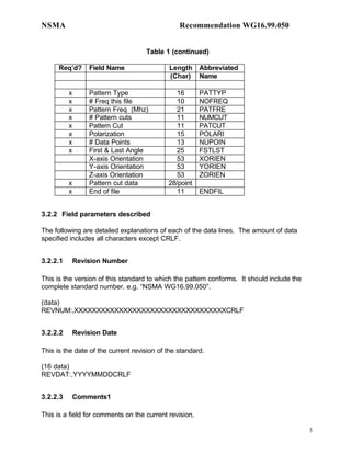
3.2 Fields
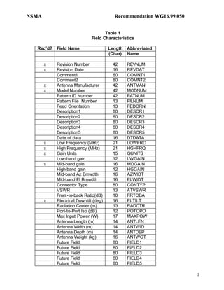
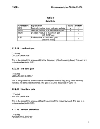
3.2.1 Field Characteristics
The fields to be used in digitized antenna patterns are defined in Table 1. They are
described in detail in subclause 3.2.2.
Per-line comments may be added to any record. In any record, all data after a “!”
character will be ignored.
1](https://image.slidesharecdn.com/nsmawg1699050-130306015835-phpapp02/85/Nsma-wg16-99_050-5-320.jpg)

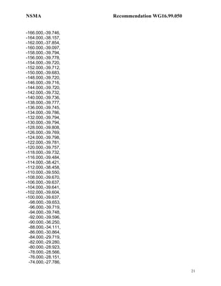
![NSMA Recommendation WG16.99.050
The angle and phase data are expressed in units of degrees.
Although pattern data is allowed values that have up to three digits to the right of the
decimal point this does not imply that the pattern data is to or can be measured to that
accuracy. Typical accuracy for an antenna pattern measurement is 0.1 dB and 0.1
degree.
For all patterns, azimuths values should not be repeated. For example, values should not
be provided for both a "0.0" degree azimuth and a "360.0" azimuth, nor should 2 different
discrimination values be provided for a "20.0" degree azimuth twice.
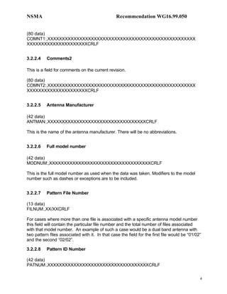
3.2.2.52 End of File
(11 data)
ENDFIL:,EOFCRLF
This field designates the end of the file with the characters EOF.
4.0 Bibliography
[1] ANSI/IEEE Std 149, IEEE Standard Test Procedures for Antennas
[2] J.S. Hollis, T.J. Lyon, L. Clayton, Microwave Antenna Measurements, Scientific-
Atlanta Georgia, 1985.
14](https://image.slidesharecdn.com/nsmawg1699050-130306015835-phpapp02/85/Nsma-wg16-99_050-18-320.jpg)

This document proposes a standard format for digitized antenna pattern data to facilitate software development and ensure consistent usage of antenna pattern data. Key elements include an overall file format with required and optional fields to describe antenna and pattern characteristics, as well as a standard way to present pattern cut data. The format is intended to be flexible enough for different antenna types, account for various pattern geometries and polarizations, and include all necessary data for propagation prediction software.