Heat and mass transfer equation; continuity equation; momentum equation;
•
1 like•698 views

Derivation of Heat and mass transfer equation through different shapes and bodies; continuity equation & momentum equation;

Recommended
More Related Content
What's hot
What's hot (20)
Similar to Heat and mass transfer equation; continuity equation; momentum equation;
Similar to Heat and mass transfer equation; continuity equation; momentum equation; (20)
More from Chandan
More from Chandan (8)
Recently uploaded
Recently uploaded (20)
Heat and mass transfer equation; continuity equation; momentum equation;
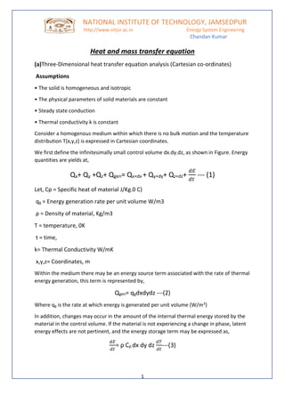
- 1. NATIONAL INSTITUTE OF TECHNOLOGY, JAMSEDPUR http://www.nitjsr.ac.in Energy System Engineering Chandan Kumar 1 Heat and mass transfer equation (a)Three-Dimensional heat transfer equation analysis (Cartesian co-ordinates) Assumptions • The solid is homogeneous and isotropic • The physical parameters of solid materials are constant • Steady state conduction • Thermal conductivity k is constant Consider a homogenous medium within which there is no bulk motion and the temperature distribution T(x,y,z) is expressed in Cartesian coordinates. We first define the infinitesimally small control volume dx.dy.dz, as shown in Figure. Energy quantities are yields at, Qx+ Qy +Qz+ Qgen= Qx+dx + Qy+dy+ Qz+dz+ 𝑑𝐸 𝑑𝑡 --- (1) Let, Cp = Specific heat of material J/Kg.0 C) qg = Energy generation rate per unit volume W/m3 ρ = Density of material, Kg/m3 T = temperature, 0K t = time, k= Thermal Conductivity W/mK x,y,z= Coordinates, m Within the medium there may be an energy source term associated with the rate of thermal energy generation, this term is represented by, Qgen= qgdxdydz ---(2) Where qg is the rate at which energy is generated per unit volume (W/m3) In addition, changes may occur in the amount of the internal thermal energy stored by the material in the control volume. If the material is not experiencing a change in phase, latent energy effects are not pertinent, and the energy storage term may be expressed as, 𝑑𝐸 𝑑𝑡 = ρ Cp dx dy dz 𝑑𝑇 𝑑𝑡 ---(3)
- 2. NATIONAL INSTITUTE OF TECHNOLOGY, JAMSEDPUR http://www.nitjsr.ac.in Energy System Engineering Chandan Kumar 2 where ρCp 𝑑𝑇 𝑑𝑡 is the time rate change of the sensible (thermal) energy of the medium per unit volume. Qx =-k dydz 𝑑𝑇 𝑑𝑥 Qy =-k dxdz 𝑑𝑇 𝑑𝑦 Qz= -k dxdy 𝑑𝑇 𝑑𝑧 Qx+dx = Qx+ 𝑑𝑄𝑥 𝑑𝑥 Qy+dy = Qy+ 𝑑𝑄𝑦 𝑑𝑦 Qz+dz = Qz+ 𝑑𝑄𝑧 𝑑𝑧 Qx+dx = Qx - k dxdydzd2T/dx2 Qy+dy = Qy - k dxdydz d2T/dy2 Qz+dz= Qz - kdxdydzd2T/dz2 Substituting in equation (1) we get, qgdxdydz= kdxdydz d2 T/dx2 - kdxdydz d2 T/dy2 - kdxdydz d2 T/dz2 + ρCpdxdydz 𝑑𝑇 𝑑𝑡 k d2 T/dx + k d2 T/dy2 + k d2 T/dz2 + qg = ρCp 𝑑𝑇 𝑑𝑡 d2 T/dx + d2 T/dy2 + d2 T/dz2 + 𝑞𝑔 𝑘 = 𝑑𝑇 𝑑 α 𝑡 ---(4) Where the quantity α = 𝑘 ρCp (m2 /s) is called thermal diffusivity of the material.
- 3. NATIONAL INSTITUTE OF TECHNOLOGY, JAMSEDPUR http://www.nitjsr.ac.in Energy System Engineering Chandan Kumar 3 Spherical coordinates Special cases Steady state one dimensional heat flow (no heat generation) Steady state one dimensional heat flow in cylindrical coordinates (no heat generation) Steady state one dimensional heat flow in Spherical coordinates (no heat generation) Steady state one dimensional heat flow (with heat generation)
- 4. NATIONAL INSTITUTE OF TECHNOLOGY, JAMSEDPUR http://www.nitjsr.ac.in Energy System Engineering Chandan Kumar 4 Two-dimensional steady state heat flow (without heat generation) (b)Heat conduction through a slab Assumptions: • One dimensional steady state heat transfer • No heat generation • The solid is homogeneous and isotropic • The physical parameters of solid materials are constant • Steady state conduction • Thermal conductivity k is constant One-dimensional heat transfer equation is, Double integrating the equation, C1 and C2 are the two constants, two boundary conditions are needed to determine the constants Boundary conditions are, Applying boundary conditions,
- 5. NATIONAL INSTITUTE OF TECHNOLOGY, JAMSEDPUR http://www.nitjsr.ac.in Energy System Engineering Chandan Kumar 5 Differentiating both sides By Fourier law, L/Ak = R is called as thermal resistance of the slab for heat flow through an area A across a temperature T1-T2 This concept analogous to electric resistance in Ohm’s law as shown in figure (c)Heat transfer through hollow cylinder Assumptions: • One dimensional steady state heat transfer, in r direction only • No heat generation • The solid is homogeneous and isotropic • The physical parameters of solid materials are constant • Thermal conductivity k is constant • Temperature within the cylinder does not vary with time One dimensional heat conduction equation,
- 6. NATIONAL INSTITUTE OF TECHNOLOGY, JAMSEDPUR http://www.nitjsr.ac.in Energy System Engineering Chandan Kumar 6 Boundary conditions, Solving simultaneous equations, By Fourier law, is called as thermal resistance of the cylinder for heat flow through an area A across a temperature Ti – To
- 7. NATIONAL INSTITUTE OF TECHNOLOGY, JAMSEDPUR http://www.nitjsr.ac.in Energy System Engineering Chandan Kumar 7 (d)Heat transfer through Sphere r1, r2, inner and outer radii Ti, To, inner and outer surface temperature L, Length of cylinder Assumptions: • One dimensional steady state heat transfer, in r direction only • No heat generation • The solid is homogeneous and isotropic • The physical parameters of solid materials are constant • Thermal conductivity k is constant One dimensional heat conduction equation, -Double Integration Boundary conditions,
- 8. NATIONAL INSTITUTE OF TECHNOLOGY, JAMSEDPUR http://www.nitjsr.ac.in Energy System Engineering Chandan Kumar 8 Solving simultaneous equations, By Fourier law, is called as thermal resistance of the Sphere for heat flow through an area A across a temperature Ti – To Composite slab
- 9. NATIONAL INSTITUTE OF TECHNOLOGY, JAMSEDPUR http://www.nitjsr.ac.in Energy System Engineering Chandan Kumar 9 **end of statement** please go to next page**
- 10. NATIONAL INSTITUTE OF TECHNOLOGY, JAMSEDPUR http://www.nitjsr.ac.in Energy System Engineering Chandan Kumar 10 Continuity Equation The continuity equation is defined as the product of cross-sectional area of the pipe and the velocity of the fluid at any given point along the pipe is constant. Continuity equation represents that the product of cross-sectional area of the pipe and the fluid speed at any point along the pipe is always constant. This product is equal to the volume flow per second or simply the flow rate. The continuity equation is given as: R = A v = constant Where, • R is the volume flow rate • A is the flow area • v is the flow velocity Following are the assumptions of continuity equation: • The tube is having a single entry and single exit • The fluid flowing in the tube is non-viscous • The flow is incompressible • The fluid flow is steady Derivation (Bernoulli’s Principle): Now, consider the fluid flows for a short interval of time in the tube. So, assume that short interval of time as Δt. In this time, the fluid will cover a distance of Δx1 with a velocity v1 at the lower end of the pipe. At this time, the distance covered by the fluid will be:
- 11. NATIONAL INSTITUTE OF TECHNOLOGY, JAMSEDPUR http://www.nitjsr.ac.in Energy System Engineering Chandan Kumar 11 Δx1 = v1Δt Now, at the lower end of the pipe, the volume of the fluid that will flow into the pipe will be: V = A1 Δx1 = A1 v1 Δt It is known that mass (m) = Density (ρ) × Volume (V). So, the mass of the fluid in Δx1 region will be: Δm1= Density × Volume Δm1 = ρ1A1v1Δt --- (1) Now, the mass flux has to be calculated at the lower end. Mass flux is simply defined as the mass of the fluid per unit time passing through any cross-sectional area. For the lower end with cross-sectional area A1, mass flux will be: Δm1/Δt = ρ1A1v1 --- (2) Similarly, the mass flux at the upper end will be: Δm2/Δt = ρ2A2v2 --- (3) Here, v2 is the velocity of the fluid through the upper end of the pipe i.e. through Δx2 , in Δt time and A2, is the cross-sectional area of the upper end. In this, the density of the fluid between the lower end of the pipe and the upper end of the pipe remains the same with time as the flow is steady. So, the mass flux at the lower end of the pipe is equal to the mass flux at the upper end of the pipe i.e. Equation 2 = Equation 3. Thus, ρ1A1v1 = ρ2A2v2 --- (4) This can be written in a more general form as: ρ A v = constant The equation proves the law of conservation of mass in fluid dynamics. Also, if the fluid is incompressible, the density will remain constant for steady flow. So, ρ1 =ρ2. Thus, Equation 4 can be now written as: A1 v1 = A2 v2 This equation can be written in general form as: A v = constant Now, if R is the volume flow rate, the above equation can be expressed as:
- 12. NATIONAL INSTITUTE OF TECHNOLOGY, JAMSEDPUR http://www.nitjsr.ac.in Energy System Engineering Chandan Kumar 12 R = A v = constant Continuity Equation in Cylindrical Coordinates Special Cases Following is the continuity equation for incompressible flow ∂ρ∂t+1r∂rρu∂r+1r∂ρv∂θ+∂ρw∂z=0 as the density, ρ = constant and is independent of space and time, we get: ∇.v = 0 Following is the continuity equation in cylindrical coordinates: 𝜕 𝜕𝑥 (ρu) + 𝜕 𝜕𝑦 (ρv) + 𝜕 𝜕𝑧 (ρw) =0 **end of statement** please go to next page**
- 13. NATIONAL INSTITUTE OF TECHNOLOGY, JAMSEDPUR http://www.nitjsr.ac.in Energy System Engineering Chandan Kumar 13 Derivation of momentum of equation: From newtons 2nd law: Newton's Second Law of motion states that the rate of change of momentum of an object is directly proportional to the applied unbalanced force in the direction of the force. If a body is subjected to multiple forces at the same time, then the acceleration produced is proportional to the vector sum (that is, the net force) of all the individual forces. ie- F = 𝑑𝑃 𝑑𝑡 = 𝑑𝑚𝑣 𝑑𝑡 p= momentum; F = m 𝑑𝑉 𝑑𝑡 = m*a V = velocity; F = m*a Where, F is the force applied, m is the mass of the body, and a, the acceleration produced. Newton’s Second Law - The net force equals the rate of change of momentum F⃗ = 𝑑𝑉⃗ 𝑀 d𝑡 For a system: F⃗ = 𝑑 𝑑𝑡 ∫SYSV⃗ dm For a control volume (via Reynolds Transport Theorem): ∑F⃗ CV= 𝑑 𝑑𝑡 ∫CVV⃗ ρdV+∫CSV⃗ ρV⃗ ⋅n^ dA
- 14. NATIONAL INSTITUTE OF TECHNOLOGY, JAMSEDPUR http://www.nitjsr.ac.in Energy System Engineering Chandan Kumar 14 (LHS 1) Body forces - weight for an element δm: δF⃗ = 𝑑 𝑑𝑡 V⃗ δm=δm 𝑑 𝑑𝑡 V⃗ =δm⋅a⃗ δF = 𝑑 𝑑𝑡 V→δm=δm 𝑑 𝑑𝑡 V→=δm⋅a→ δF⃗ b=δm⋅g⃗ =ρδxδyδz⋅g⃗ (LHS 2) Normal force and Tangential force Subscript notation: • 1st subscript refers to the direction of the normal vector • 2nd subscript refers to the direction of the stress vector Sign convention: • Normal Stress is positive if it’s in the same direction as the outward normal vector • Shear Stress is positive if it’s in the same direction as the coordinate system w.r.t the outward normal vector (i.e. the right hand rule applies - thumb is the direction of the outward normal vector, the two fingers are the shear stresses) Conservation of Momentum in x-direction: δFsx=(∂σxx/∂x+∂τyx/∂y+∂τzx/∂z)δxδyδz Conservation of Momentum in y-direction: δFsy=(∂τxy/∂x+∂σyy/∂y+∂τzy/∂z)δxδyδz Conservation of Momentum in z-direction: δFsz=(∂τxz/∂x+∂τyz/∂y+∂σzz/∂z)δxδyδz
- 15. NATIONAL INSTITUTE OF TECHNOLOGY, JAMSEDPUR http://www.nitjsr.ac.in Energy System Engineering Chandan Kumar 15 ρgx+∂σxx/∂x+∂τyx/∂y+∂τzx/∂z=ρ(∂u/∂t+u∂u/∂x+v∂u/∂y+w∂u/∂z) ρgy+∂τxy/∂x+∂σyy/∂y+∂τzy/∂z=ρ(∂v/∂t+u∂v/∂x+v∂v/∂y+w∂v/∂z) ρgz+∂τxz/∂x+∂τyz/∂y+∂σzz/∂z=ρ(∂w/∂t+u∂w/∂x+v∂w/∂y+w∂w/∂z) from these three equations + continuity = Four equations we can conclude that- Inviscid flow - no shearing stresses σxx=σyy=σzz=−p Euler’s Equation in the x-direction ρgx− 𝛛𝐩 𝛛𝐱 = ρ( 𝛛𝐮 𝛛𝐭 +u 𝛛𝐮 𝛛𝐱 +v 𝛛𝐮 𝛛𝐲 +w 𝛛𝐮 𝛛𝐳 ) Vector Notation: ρg⃗ −∇p=ρ( ∂V⃗ ∂t +V⃗ (∇⋅V⃗ ) **end**