Download as PDF, PPTX
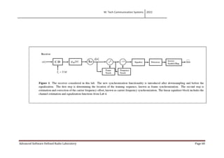
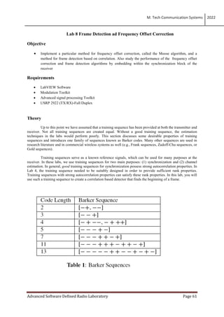
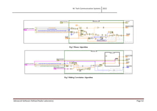

This lab aims to implement a frequency offset correction algorithm called Moose and a frame detection method using correlation. Students will study the performance of these algorithms by incorporating them in a receiver synchronization block. The lab covers the Moose algorithm, sliding correlation algorithm and procedures to test them over a real wireless link between a USRP transmitter and receiver. Students are asked questions about the impact of frequency offsets, properties of training sequences, and challenges faced in implementing the systems.