This document is the 2005 edition of NFPA 70, the National Electrical Code (NEC). It provides the requirements for electrical installations in the United States, including wiring, overcurrent protection, grounding, and equipment specifications. The NEC is developed through a consensus process by the NFPA and is revised on a three-year cycle. This edition supersedes all previous editions and marks the 50th edition of the NEC. Changes from the previous edition are indicated by rules in the margin.
![NATIONAL ELECTRICAL CODE COMMITTEE
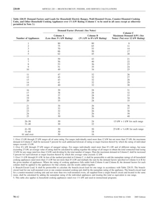
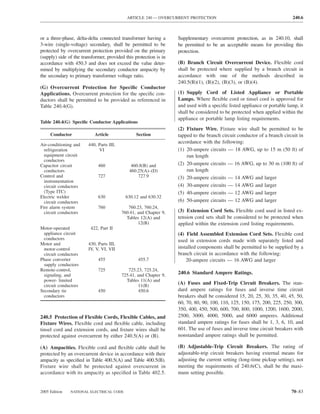
NATIONAL ELECTRICAL CODE COMMITTEE
These lists represent the membership at the time the Committee was balloted on the final text of this edition. Since
that time, changes in the membership may have occurred. A key to classifications is found at the back of this
document.
Technical Correlating Committee
James W. Carpenter, Chair
International Association of Electrical Inspectors, TX [E]
Rep. International Association of Electrical Inspectors
Mark W. Earley, Secretary
NFPA, MA
(nonvoting)
Jean A. O’Connor, Recording Secretary
NFPA, MA
(nonvoting)
James E. Brunssen, Telcordia, NJ [UT] James M. Daly, General Cable, NJ [M]
Rep. Alliance for Telecommunications Industry Solutions Rep. National Electrical Manufacturers Association
Michael I. Callanan, National Joint Apprentice & Training (Alt. to J. T. Pauley)
Committee, MD [L] Stanley J. Folz, Folz Electric, Incorporated, IL [IM]
Rep. International Brotherhood of Electrical Workers Rep. National Electrical Contractors Association
William R. Drake, Marinco, CA [M] (Alt. to M. D. Toman)
John R. Kovacik, Underwriters Laboratories Incorporated, Palmer L. Hickman, National Joint Apprentice & Training
IL [RT] Committee, MD [L]
James T. Pauley, Square D Company, KY [M] Rep. International Brotherhood of Electrical Workers
Rep. National Electrical Manufacturers Association (Alt. to M. I. Callanan)
Michael D. Toman, MEGA Power Electrical Services, Neil F. LaBrake, Jr., Niagara Mohawk, a National Grid
Incorporated, MD [IM]
Company, NY [UT]
Rep. National Electrical Contractors Association
Rep. Electric Light & Power Group/EEI
John W. Troglia, Edison Electric Institute, WI [UT]
Rep. Electric Light & Power Group/EEI (Alt. to J. W. Troglia)
Craig M. Wellman, DuPont Engineering, DE [U] William M. Lewis, Eli Lilly & Company, IN [U]
Rep. American Chemistry Council Rep. American Chemistry Council
(Alt. to C. M. Wellman)
Alternates Mark C. Ode, Underwriters Laboratories Incorporated,
Jeffrey Boksiner, Telcordia Technologies, Incorporated, NC [RT]
NJ [UT] (Alt. to J. R. Kovacik)
Rep. Alliance for Telecommunications Industry Solutions Nonvoting
(Alt. to J. E. Brunssen)
Philip H. Cox, Bigelow, AR [E] Richard G. Biermann, Biermann Electric Company,
Rep. International Association of Electrical Inspectors Incorporated, IA [IM]
(Alt. to J. W. Carpenter) D. Harold Ware, Libra Electric Company, OK [IM]
CODE–MAKING PANEL NO. 1
Articles 90, 100, 110, Annex A, Annex G
John D. Minick, Chair
National Electrical Manufacturers Association, TX [M]
Rep. National Electrical Manufacturers Association
Michael A. Anthony, University of Michigan, MI [U] H. Landis Floyd II, The DuPont Company, DE [U]
Rep. The Association of Higher Education Facilities Rep. Institute of Electrical & Electronics Engineers,
Officers Incorporated
Louis A. Barrios, Jr., Shell Global Solutions, TX [U] Palmer L. Hickman, National Joint Apprentice & Training
Rep. American Chemistry Council Committee, MD [L]
David A. Dini, Underwriters Laboratories Incorporated, Rep. International Brotherhood of Electrical Workers
IL [RT] David L. Hittinger, IEC of Greater Cincinnati, OH [IM]
William T. Fiske, Intertek Testing Services NA, Rep. Independent Electrical Contractors, Incorporated
Incorporated, NY [RT]
2005 Edition NATIONAL ELECTRICAL CODE 70–9](https://image.slidesharecdn.com/nechandbookversin2005compacta-100921141249-phpapp02/85/Nec-handbook-version-2005-compacta-12-320.jpg)
![NATIONAL ELECTRICAL CODE COMMITTEE
Randall R. McCarver, Telcordia Technologies, Incorporated, Neil F. LaBrake, Jr., Niagara Mohawk, a National Grid
NJ [U] Company, NY [UT]
Rep. Alliance for Telecommunications Industry Solutions Rep. Electric Light & Power Group/EEI
Lanny G. McMahill, City of Phoenix, AZ [E] (Alt. to J. W. Troglia)
Rep. International Association of Electrical Inspectors Donald H. McCullough, II, Westinghouse Savannah River
H. Brooke Stauffer, National Electrical Contractors Company, SC [U]
Association, MD [IM] Rep. Institute of Electrical & Electronics Engineers,
Rep. National Electrical Contractors Association Incorporated
John W. Troglia, Edison Electric Institute, WI [UT] (Alt. to H. L. Floyd II)
Rep. Electric Light & Power Group/EEI
Gil Moniz, National Electrical Manufacturers Association,
Alternates MA [M]
Rep. National Electrical Manufacturers
Lawrence S. Ayer, Biz Com Electric, Incorporated, OH [IM]
Association
Rep. Independent Electrical Contractors, Incorporated
(Alt. to J. D. Minick)
(Alt. to D. L. Hittinger)
Kenneth P. Boyce, Underwriters Laboratories Incorporated, Rick Munch, Frischhertz Electric Company, LA [L]
IL [RT] Rep. International Brotherhood of Electrical
(Alt. to D. A. Dini) Workers
Ernest J. Gallo, Telcordia Technologies, Incorporated, NJ [U] (Alt. to P. L. Hickman)
Rep. Alliance for Telecommunications Industry Solutions
(Alt. to R. R. McCarver)
Russell J. Helmick, Jr., City of Irvine, CA [E]
Nonvoting
Rep. International Association of Electrical Inspectors Ark Tsisserev, City of Vancouver, BC, Canada
(Alt. to L. G. McMahill) Rep. Canadian Standards Association International
CODE–MAKING PANEL NO. 2
Articles 210, 215, 220, Annex D, Examples 1 through 6
Raymond W. Weber, Chair
State of Wisconsin, WI [E]
Rep. International Association of Electrical Inspectors
Richard W. Becker, Engineered Electrical Systems, Ernest S. Broome, City of Knoxville, TN [E]
Incorporated, WA [U] Rep. International Association of Electrical Inspectors
Rep. Institute of Electrical & Electronics Engineers, (Alt. to R. W. Weber)
Incorporated James R. Jones, University of Alabama at Birmingham, AL
Frank Coluccio, New York City Department of Buildings, [U]
NY [E] Rep. Institute of Electrical & Electronics Engineers,
Matthew D. Dobson, National Association of Home Incorporated
Builders, DC [U] (Alt. to R. W. Becker)
Rep. National Association of Home Builders Daniel J. Kissane, Pass & Seymour/Legrand, NY [M]
Thomas L. Harman, University of Houston/Clear Lake, TX
Rep. National Electrical Manufacturers Association
[SE]
(Alt. to J. T. Pauley)
Donald M. King, IBEW Local Union 313, DE [L]
Rep. International Brotherhood of Electrical Workers Brian J. Nenninger, The Dow Chemical Company, TX [U]
Christopher P. O’Neil, National Grid USA Service Rep. American Chemistry Council
Company, MA (Alt. to J. P. Roché)
Rep. Electric Light & Power Group/EEI, MA Clifford L. Rediger, Independent Electrical Contractors
James T. Pauley, Square D Company, KY [M] Training Fund, CO [IM]
Rep. National Electrical Manufacturers Association Rep. Independent Electrical Contractors, Incorporated
Susan W. Porter, Underwriters Laboratories Incorporated, (Alt. to R. G. Wilkinson)
NY [RT] Richard V. Wagner, Underwriters Laboratories Incorporated,
Joseph Patterson Roché, Celanese Acetate, SC [U] NY [RT]
Rep. American Chemistry Council (Alt. to S. W. Porter)
Albert F. Sidhom, U.S. Army Corps of Engineers, CA [U] Joseph E. Wiehagen, National Association of Home
Michael D. Toman, MEGA Power Electrical Services, Builders, MD [U]
Incorporated, MD [IM] Rep. National Association of Home Builders
Rep. National Electrical Contractors Association (Alt. to M. D. Dobson)
Robert G. Wilkinson, Independent Electrical Contractors of
Texas Gulf Coast, TX [IM] Nonvoting
Rep. Independent Electrical Contractors, Incorporated
Douglas A. Lee, U.S. Consumer Product Safety
Alternates Commission, MD [C]
Kevin J. Brooks, IBEW Local Union 16, IN [L] Andrew M. Trotta, U.S. Consumer Product Safety
Rep. International Brotherhood of Electrical Workers Commission, MD [C]
(Alt. to D. M King) (Alt. to D. A. Lee)
70–10 NATIONAL ELECTRICAL CODE 2005 Edition](https://image.slidesharecdn.com/nechandbookversin2005compacta-100921141249-phpapp02/85/Nec-handbook-version-2005-compacta-13-320.jpg)
![NATIONAL ELECTRICAL CODE COMMITTEE
CODE–MAKING PANEL NO. 3
Articles 300, 590, 720, 725, 727, 760, Chapter 9, Tables 11(a) and (b), and Tables 12(a) and (b)
Richard P. Owen, Chair
City of St. Paul, MN [E]
Rep. International Association of Electrical Inspectors
Lawrence S. Ayer, Biz Com Electric, Incorporated, OH [IM] Adam D. Corbin, Corbin Electrical Services, Incorporated,
Rep. Independent Electrical Contractors, Incorporated NJ [IM]
Paul J. Casparro, Scranton Electricians JATC, PA [L] Rep. Independent Electrical Contractors, Inc.
Rep. International Brotherhood of Electrical Workers (Alt. to L. S. Ayer)
Les Easter, Allied Tube and Conduit, IL [M] John C. Hudak, Old Forge, PA [E]
Rep. National Electrical Manufacturers Association Rep. International Association of Electrical Inspectors
Sanford E. Egesdal, Egesdal Associates PLC, MN [M] (Alt. to R. P. Owen)
Rep. Automatic Fire Alarm Association, Incorporated Danny Liggett, DuPont Engineering, DE [U]
Thomas J. Guida, Underwriters Laboratories, Inc., NY [RT] Rep. American Chemistry Council
Dennis B. Horman, PacifiCorp, UT [UT] (Alt. to D. A. Pace)
Rep. Electric Light & Power Group/EEI Juan C. Menendez, Southern California Edison Company,
Ray R. Keden, ERICO, Incorporated, CA [M] CA [UT]
Rep. Building Industry Consulting Services International Rep. Electric Light & Power Group/EEI
Ronald E. Maassen, Lemberg Electric Company,
(Alt. to D. B. Horman)
Incorporated, WI [IM]
T. David Mills, Bechtel Savannah River, Incorporated,
Rep. National Electrical Contractors Association
SC [U]
Steven J. Owen, Steven J. Owen, Incorporated, AL [IM]
Rep. Associated Builders and Contractors, Incorporated Rep. Institute of Electrical & Electronics Engineers,
David A. Pace, Olin Corporation, AL [U] Incorporated
Rep. American Chemistry Council (Alt. to M. K. Sanders)
Melvin K. Sanders, Things Electrical Company, Mark C. Ode, Underwriters Laboratories Incorporated,
Incorporated (TECo., Incorporated), IA [U] NC [RT]
Rep. Institute of Electrical & Electronics Engineers, (Alt. to T. J. Guida)
Incorporated Lorena Orbanic, Carlon, Lamson & Sessions, OH [M]
John E. Sleights, Travelers Insurance, CT [I] Rep. Building Industry Consulting Services International
(Alt. to R. R. Keden)
Alternates Roger S. Passmore, Davis Electrical Constructors,
Mark E Christian, Chattanooga Electrical JATC, TN [L] Incorporated, SC [IM]
Rep. International Brotherhood of Electrical Workers Rep. Associated Builders and Contractors, Incorporated
(Alt. to P. J. Casparro) (Alt. to S. J. Owen)
Dr. Shane M. Clary, Bay Alarm Company, Incorporated, George A. Straniero, AFC Cable Systems, Incorporated,
CA [M] NJ [M]
Rep. Automatic Fire Alarm Association, Incorporated Rep. National Electrical Manufacturers Association
(Alt. to S. E. Egesdal) (Alt. to L. Easter)
CODE–MAKING PANEL NO. 4
Articles 225, 230
James M. Naughton, Chair
IBEW Local Union 103, MA [L]
Rep. International Brotherhood of Electrical Workers
Malcolm Allison, Ferraz Shawmut, MA [M] John W. Young, Siemens Energy & Automation,
C. John Beck, Pacific Gas and Electric Company, Incorporated, GA [M]
CA [UT] Rep. National Electrical Manufacturers Association
Rep. Electric Light & Power Group/EEI Vincent Zinnante, Advantage Electric, Incorporated,
Robert J. Deaton, The Dow Chemical Company, TX [U] TX [IM]
Rep. Institute of Electrical & Electronics Engineers, Rep. Independent Electrical Contractors, Incorporated
Incorporated
Howard D. Hughes, Hughes Electric Company Alternates
Incorporated, AR [IM] Thomas L. Adams, Exelon Corporation, IL [UT]
Rep. National Electrical Contractors Association Rep. Electric Light & Power Group/EEI
William M. Lewis, Eli Lilly & Company, IN [U] (Alt. to C. J. Beck)
Rep. American Chemistry Council Ronald Breschini, Underwriters Laboratories Incorporated,
Mark C. Ode, Underwriters Laboratories Incorporated, CA [RT]
NC [RT] (Alt. to M. C. Ode)
James J. Rogers, Towns of Oak Bluffs, Tisbury, West Terry D. Cole, Hamer Electric, WA [IM]
Tisbury, MA [E] Rep. Independent Electrical Contractors, Incorporated
Rep. International Association of Electrical Inspectors (Alt. to V. Zinnante)
2005 Edition NATIONAL ELECTRICAL CODE 70–11](https://image.slidesharecdn.com/nechandbookversin2005compacta-100921141249-phpapp02/85/Nec-handbook-version-2005-compacta-14-320.jpg)
![NATIONAL ELECTRICAL CODE COMMITTEE
Mark R. Hilbert, State of New Hampshire, NH [E] John Sigmund, PPG Industries, Incorporated,
Rep. International Association of Electrical Inspectors LA [U]
(Alt. to J. J. Rogers) Rep. American Chemistry Council
Philip M. Piqueira, General Electric Company, CT [M] (Alt. to W. M. Lewis)
Rep. National Electrical Manufacturers Association
Mark H. Sumrall, IBEW Local Union 527, TX [L]
(Alt. to J. W. Young)
Francis E. Rose, Jr., W. S. Nelson and Company, Rep. International Brotherhood of Electrical
Workers
Incorporated, LA [U]
Rep. Institute of Electrical & Electronics Engineers, (Alt. to J. M. Naughton)
Incorporated Kent Walker, Ferraz Shawmut, MA [M]
(Alt. to R. J. Deaton) (Alt. to M. Allison)
CODE-MAKING PANEL NO. 5
Articles 200, 250, 280, 285
Ronald J. Toomer, Chair
Toomer Electrical Company Incorporated, LA [IM]
Rep. National Electrical Contractors Association
Jeffrey Boksiner, Telcordia Technologies, Incorporated, Alternates
NJ [UT]
Martin D. Adams, Adams Electric, Incorporated, CO [IM]
Rep. Alliance for Telecommunications Industry
Rep. National Electrical Contractors Association
Solutions
(Alt. to R. J. Toomer)
David T. Brender, Copper Development Association, David A. Dini, Underwriters Laboratories Incorporated, IL
Incorporated, NY [M] [RT]
Rep. Copper Development Association, Incorporated (Alt. to W. Skuggevig)
Martin J. Brett, Jr., Wheatland Tube Company, Timothy Edwards, Alcan Cable Company, GA [M]
NJ [M] Rep. The Aluminum Association
Rep. American Iron and Steel Institute (Alt. to G. L. Hadeen)
Elio L. Checca, U.S. Department of Labor, VA [E] Robert Figlia, New York Board of Fire Underwriters, NY
Paul Dobrowsky, Eastman Kodak Company, NY [U] [E]
Rep. American Chemistry Council Rep. International Association of Electrical Inspectors
Gerald L. Hadeen, Tehachapi, CA [M] (Alt. to M. J. Johnston)
Rep. The Aluminum Association G. Scott Harding, F. B. Harding, Incorporated, MD [IM]
Dan Hammel, IBEW Local Union 704, IA [L] Rep. Independent Electrical Contractors, Incorporated
Rep. International Brotherhood of Electrical Workers (Alt. to T. G. Robertson)
Michael J. Johnston, International Association of Electrical William J. Helfrich, U.S. Department of Labor, PA [E]
Inspectors, TX [E] (Alt. to E. L. Checca)
Rep. International Association of Electrical Inspectors Ronald Lai, FCI Electrical, NH [M]
Charles Mello, Electro-Test, Incorporated, OR [IM] Rep. National Electrical Manufacturers Association
Rep. InterNational Electrical Testing Association (Alt. to G. J. Steinman)
Incorporated Paul J. LeVasseur, Bay City JEATC, MI [L]
Rep. International Brotherhood of Electrical Workers
Elliot Rappaport, Electro Technology Consultants,
Incorporated, FL [U] (Alt. to D. Hammel)
Rep. Institute of Electrical & Electronics Engineers, Richard E. Loyd, R & N Associates, AZ [M]
Incorporated Rep. American Iron and Steel Institute
(Alt. to M. J. Brett, Jr.)
Ted G. Robertson, Robertson Electric, Incorporated,
Daleep C. Mohla, DCM Electrical Consulting Services,
TX [IM]
Incorporated, TX [U]
Rep. Independent Electrical Contractors, Incorporated
Rep. Institute of Electrical & Electronics Engineers,
Walter Skuggevig, Underwriters Laboratories Incorporated, Incorporated
NY [RT] (Alt. to E. Rappaport)
Gregory J. Steinman, Thomas & Betts Corporation, David Peot, Ryobi, SC [M]
TN [M] Rep. Power Tool Institute, Incorporated
Rep. National Electrical Manufacturers Association (Alt. to R. G. Stoll)
Robert G. Stoll, Thomas Associates, Incorporated, J. Philip Simmons, Simmons Electrical Services, WA [M]
OH [M] Rep. Copper Development Association, Incorporated
Rep. Power Tool Institute, Incorporated (Alt. to D. T. Brender)
C. Douglas White, CenterPoint Energy, Incorporated, James S. Simpson, Southern Company Services, AL [UT]
TX [UT] Rep. Electric Light & Power Group/EEI
Rep. Electric Light & Power Group/EEI (Alt. to C. D.White)
70–12 NATIONAL ELECTRICAL CODE 2005 Edition](https://image.slidesharecdn.com/nechandbookversin2005compacta-100921141249-phpapp02/85/Nec-handbook-version-2005-compacta-15-320.jpg)
![NATIONAL ELECTRICAL CODE COMMITTEE
CODE-MAKING PANEL NO. 6
Articles 310, 400, 402, Chapter 9 Tables 5 through 9, Annex B
Stephen J. Thorwegen, Jr., Chair
Fisk Electric Company, TX [IM]
Rep. National Electrical Contractors Association
Robert Edwards, Alcan Aluminum Corporation, ON, James M. Daly, General Cable, NJ [M]
Canada [M] Rep. Copper Development Association, Incorporated
Rep. The Aluminum Association (Alt. to J. S. Zimnoch)
Samuel B. Friedman, BICC General Cable Corporation, Robert L. Huddleston, Jr., Eastman Chemical Company,
RI [M] TN [U]
Rep. National Electrical Manufacturers Association Rep. American Chemistry Council
G. W. “Jerry” Kent, Kent Electric & Plumbing Systems, (Alt. to D. P. Liggett)
TX [IM] Philip T. Laudicini, Underwriters Laboratories Incorporated,
Rep. Independent Electrical Contractors, Incorporated NY [RT]
David G. Komassa, WE Energies, WI [UT] (Alt. to A. D. Wetherell)
Rep. Electric Light & Power Group/EEI Lowell S. Lisker, American Insulated Wire Corporation,
William F. Laidler, South Shore VoTech/IBEW 223, MA [L] RI [M]
Rep. International Brotherhood of Electrical Workers Rep. National Electrical Manufacturers Association
Danny P. Liggett, DuPont Engineering, TX [U] (Alt. to S. B. Friedman)
Rep. American Chemistry Council Paul R. Picard, AFC Cable Systems, Incorporated, MA [M]
L. Bruce McClung, Electrical Safety Consulting Services, Rep. The Aluminum Association
Incorporated, WV [U] (Alt. to R. Edwards)
Rep. Institute of Electrical & Electronics Engineers, Harry J. Sassaman, Forest Electric Corporation, NJ [IM]
Incorporated Rep. National Electrical Contractors Association
Oran P. Post, City of Cuyahoga Falls, OH [E] (Alt. to S. J. Thorwegen, Jr.)
Rep. International Association of Electrical Inspectors John Stacey, City of St. Louis, MO [E]
Austin D. Wetherell, Underwriters Laboratories Rep. International Association of Electrical Inspectors
Incorporated, NY [RT] (Alt. to O. P. Post)
Joseph S. Zimnoch, The Okonite Company, NJ [M] Donald A. Voltz, Mustang Engineering, Incorporated,
Rep. Copper Development Association, Incorporated TX [U]
Rep. Institute of Electrical & Electronics Engineers,
Alternates Incorporated
Peter E. Bowers, Satellite Electric Company, Incorporated, (Alt. to L. B. McClung)
MD [IM] David R. Wellington, Toledo Electrical JATC, OH [L]
Rep. Independent Electrical Contractors, Incorporated Rep. International Brotherhood of Electrical Workers
(Alt. to G. W. Kent) (Alt. to W. F. Laidler)
CODE-MAKING PANEL NO. 7
Articles 320, 322, 324, 326, 328, 330, 332, 334, 336, 338, 340, 382, 394, 396, 398
Gaylen D. Rogers, Chair
State of Utah, UT [E]
Rep. International Association of Electrical Inspectors
James J. Anastasi, Intertek/ETL Semko, NY [RT] Gregory L. Runyon, Eli Lilly and Company, IN [U]
Harry C. Brown, IBEW Local Union 606, FL [L] Rep. American Chemistry Council
Rep. International Brotherhood of Electrical David E. Schumacher, All County Electric Company,
Workers IA [IM]
John J. Cangemi, Underwriters Laboratories Incorporated, Rep. Associated Builders and Contractors, Incorporated
NY [RT] H. R. Stewart, HRS Consulting, TX [U]
James M. Daly, General Cable, NJ [M] Rep. Institute of Electrical & Electronics Engineers,
Rep. National Electrical Manufacturers Association Incorporated
Chris J. Fahrenthold, Encompass Electrical Technologies, George A. Straniero, AFC Cable Systems, Incorporated,
TX [IM] NJ [M]
Rep. Independent Electrical Contractors, Incorporated Rep. Copper Development Association, Incorporated
Richard Temblador, Alflex Corporation, CA [M]
Robert L. Gotham, Rose City Electric Company, Rep. The Aluminum Association
Incorporated, OR [IM]
Rep. National Electrical Contractors Association Alternates
Herman J. Hall, Austin, TX [M] William B. Crist, Houston Stafford Electric Company,
Rep. Society of the Plastics Industry Incorporated TX [IM]
Ronald G. Nickson, National Multi Housing Council, Rep. Independent Electrical Contractors, Incorporated
DC [U] (Alt. to C. J. Fahrenthold)
Rep. National Multi Housing Council James D. Erwin, Celanese, Limited, TX [U]
Bruce W. Nutt, Oncor, TX [UT] Rep. American Chemistry Council
Rep. Electric Light & Power Group/EEI (Alt. to G. L. Runyon)
2005 Edition NATIONAL ELECTRICAL CODE 70–13](https://image.slidesharecdn.com/nechandbookversin2005compacta-100921141249-phpapp02/85/Nec-handbook-version-2005-compacta-16-320.jpg)
![NATIONAL ELECTRICAL CODE COMMITTEE
James K. Hinrichs, State of Washington, WA [E] John W. “Wes” Ray, Duke Energy Corporation, NC [UT]
Rep. International Association of Electrical Inspectors Rep. Electric Light & Power Group/EEI
(Alt. to G. D. Rogers) (Alt. to B. W. Nutt)
Samuel R. LaDart, City of Memphis, TN [L] David K. Smith, Encore Wire Limited, TX [M]
Rep. International Brotherhood of Electrical Workers Rep. Copper Development Association, Incorporated
(Alt. to H. C. Brown) (Alt. to G. A. Straniero)
C. David Mercier, Southwire Company, GA [M] John Thomas Thompson, ABC Marathon Electrical
Rep. National Electrical Manufacturers Association
Company, Incorporated, AL [IM]
(Alt. to J. M. Daly)
Rep. Associated Builders and Contractors, Incorporated
Dennis A. Nielsen, Lawrence Berkeley National Laboratory,
CA [U] (Alt. to D. E. Schumacher)
Rep. Institute of Electrical & Electronics Engineers, Larry G. Watkins, Alcan Aluminum Corporation, GA [M]
Incorporated Rep. The Aluminum Association
(Alt. to H. R. Stewart) (Alt. to R. Temblador)
Paul A. Orr, Underwriters Laboratories Incorporated, Thomas H. Wood, Cecil B. Wood Incorporated, IL [IM]
NY [RT] Rep. National Electrical Contractors Association
(Alt. to J. J. Cangemi) (Alt. to R. L. Gotham)
CODE-MAKING PANEL NO. 8
Articles 342, 344, 348, 350, 352, 353, 354, 356, 358, 360, 362, 366, 368, 370, 372, 374, 376, 378, 380, 384,
386, 388, 390, 392, Chapter 9 Tables 1 through 4, Annex C
Julian R. Burns, Chair
Burns Electrical/Quality Power Solutions, Incorporated, NC [IM]
Rep. Independent Electrical Contractors, Incorporated
John S. Corry, Corry Electric Incorporated, CA [IM] Charles W. Forsberg, Shaker Heights, OH [M]
Rep. Associated Builders and Contractors, Incorporated Rep. Society of the Plastics Industry Incorporated
Joseph G. Dabe, City of St. Paul, MN [L] (Alt. to D. H. Kendall)
Rep. International Brotherhood of Electrical Workers Dr. Jack A. Gruber, Wheatland Tube Company, PA [M]
George R. Dauberger, Thomas & Betts Corporation, TN [M] Rep. American Iron and Steel Institute
Rep. National Electrical Manufacturers Association (Alt. to R. E. Loyd)
James C. Dollins, AFC Cable Systems, MA [M] James M. Imlah, City of Hillsboro, OR [E]
Rep. The Aluminum Association Rep. International Association of Electrical Inspectors
Ronald E. Duren, PacifiCorp, WA [UT]
(Alt. to W. A. Lilly)
Rep. Electric Light & Power Group/EEI
Alan Manche, Schneider Electric/Square D Company,
M. Shan Griffith, Kelloff, Brown & Root, Incorporated,
TX [U] KY [M]
Rep. Institute of Electrical & Electronics Engineers, Rep. National Electrical Manufacturers Association
Incorporated (Alt. to G. R. Dauberger)
David H. Kendall, Carlon, Lamson & Sessions, OH [M] Jamie McNamara, City of St. Paul, MN [L]
Rep. Society of the Plastics Industry Incorporated Rep. International Brotherhood of Electrical Workers
Wayne A. Lilly, City of Harrisonburg, VA [E] (Alt. to J. G. Dabe)
Rep. International Association of Electrical Inspectors C. Ernest Reynolds, Hatfield-Reynolds Electric Company,
Richard E. Loyd, R & N Associates, AZ [M] AZ [IM]
Rep. American Iron and Steel Institute Rep. Independent Electrical Contractors, Incorporated
Stephen P. Poholski, Newkirk Electric Associates, (Alt. to J. R. Burns)
Incorporated, MI [IM] Richard Temblador, Alflex Corporation, CA [M]
Rep. National Electrical Contractors Association Rep. The Aluminum Association
Dennis L. Rowe, New York Board of Fire Underwriters, (Alt. to J. C. Dollins)
NY [E] Ronald J. Toomer, Toomer Electrical Company
Rep. New York Board of Fire Underwriters Incorporated, LA [IM]
George F. Walbrecht, Underwriters Laboratories Rep. National Electrical Contractors Association
Incorporated, IL [RT]
(Alt. to S. P. Poholski)
Alternates James Van Den Heuvel, West Electric Incorporated,
WI [IM]
Richard Berman, Underwriters Laboratories Incorporated,
Rep. Associated Builders and Contractors, Incorporated
IL [RT]
(Alt. to G. F. Walbrecht) (Alt. to J. S. Corry)
Duane A. Carlson, PRS Consulting Engineers, WA [U] Leslie R. Zielke, South Carolina Electric & Gas Company,
Rep. Institute of Electrical & Electronics Engineers, SC [UT]
Incorporated Rep. Electric Light & Power Group/EEI
(Alt. to M. S. Griffith) (Alt. to R. E. Duren)
70–14 NATIONAL ELECTRICAL CODE 2005 Edition](https://image.slidesharecdn.com/nechandbookversin2005compacta-100921141249-phpapp02/85/Nec-handbook-version-2005-compacta-17-320.jpg)
![NATIONAL ELECTRICAL CODE COMMITTEE
CODE-MAKING PANEL NO. 9
Articles 312, 314, 404, 408, 450, 490
Timothy M. Croushore, Chair
Allegheny Power, PA [UT]
Rep. Electric Light & Power Group/EEI
Jeffery Bernson, IBEW Local Union 701, IL [L] Joseph M. Bolesina, Pinellas County Building Inspections,
Rep. International Brotherhood of Electrical Workers FL [E]
Hector R. de Vega, Fluor Daniel, TX [U] Rep. International Association of Electrical Inspectors
Rep. Associated Builders and Contractors, Incorporated (Alt. to D. R. Offerdahl)
Frederic P. Hartwell, Hartwell Electrical Services, MA [SE] Julian R. Burns, Burns Electrical/Quality Power Solutions,
Robert J. Kaemmerlen, Kaemmerlen Electric Company, Incorporated, NC [IM]
MO [IM] Rep. Independent Electrical Contractors, Incorporated
Rep. National Electrical Contractors Association
(Alt. to T. J. LeMay)
Jacob Killinger, Underwriters Laboratories Incorporated,
IL [RT] James C. Carroll, Square D Company, TN [M]
Thomas J. LeMay, LeMay Electric, Incorporated, GA [IM] Rep. National Electrical Manufacturers Association
Rep. Independent Electrical Contractors, Incorporated (Alt. to B. D. Rupp)
Donald R. Offerdahl, North Dakota State Electrical Board, Richard P. Fogarty, Consolidated Edison Company of NY,
ND [E] Incorporated, NY [UT]
Rep. International Association of Electrical Inspectors Rep. Electric Light & Power Group/EEI
Bradford D. Rupp, Allied Moulded Products, Incorporated, (Alt. to T. M. Croushore)
OH [M] Robert D. Osborne, Underwriters Laboratories Incorporated,
Rep. National Electrical Manufacturers Association NC [RT]
Sukanta Sengupta, FMC Corporation, NJ [U] (Alt. to J. Killinger)
Rep. Institute of Electrical & Electronics Engineers, Jerome W. Seigel, West Hartford, CT [U]
Incorporated Rep. Institute of Electrical & Electronics Engineers,
Ralph H. Young, Eastman Chemical Company, TN [U] Incorporated
Rep. American Chemistry Council
(Alt. to S. Sengupta)
Alternates Monte Szendre, Wilson Construction Company, OR [IM]
Rep. National Electrical Contractors Association
Rodney D. Belisle, NECA-IBEW Training Center, WA [L]
(Alt. to R. J. Kaemmerlen)
Rep. International Brotherhood of Electrical Workers
(Alt. to L. Bernson)
CODE-MAKING PANEL NO. 10
Articles 240, 780
James T. Dollard, Jr., Chair
IBEW Local Union 98, PA [L]
Rep. International Brotherhood of Electrical Workers
Charles K. Blizard, American Electrical Testing Company, John A. Zaplatosch, Underwriters Laboratories
Incorporated, MA [IM] Incorporated, IL [RT]
Rep. InterNational Electrical Testing Association
Incorporated Alternates
Madeline Borthick, IEC of Houston, Incorporated, TX [IM] Robert R. Gage, Niagara Mohawk, A National Grid
Rep. Independent Electrical Contractors, Incorporated Company, NY [UT]
Scott Cline, McMurtrey Electric, Incorporated, CA [IM] Rep. Electric Light & Power Group/EEI
Rep. National Electrical Contractors Association (Alt. to C. K. Eldridge)
Dennis M. Darling, Ayres, Lewis, Norris & May, George D. Gregory, Square D Company, IA [M]
Incorporated, MI [U] Rep. National Electrical Manufacturers Association
Rep. Institute of Electrical & Electronics Engineers, (Alt. to C. W. Kimblin)
Incorporated Roderic L. Hageman, PRIT Service, Incorporated, IL [IM]
Charles K. Eldridge, Indianapolis Power & Light Company, Rep. InterNational Electrical Testing Association
IN [UT] Incorporated
Rep. Electric Light & Power Group/EEI (Alt. to C. K. Blizard)
Carl J. Fredericks, The Dow Chemical Company, TX [U] Charles D. Hughes, Westinghouse Savannah River
Rep. American Chemistry Council Company, SC [U]
C. W. Kimblin, Cutler-Hammer, Incorporated, PA [M] Rep. Institute of Electrical & Electronics Engineers,
Rep. National Electrical Manufacturers Association Incorporated
Arden L. Munson, Hussmann Corporation, MO [M] (Alt. to D. M. Darling)
Rep. Air-Conditioning and Refrigeration Institute Robert J. Kauer, Middle Department Inspection Agency,
George J. Ockuly, Chesterfield, MO [M] Incorporated, PA [E]
Gerald W. Williams, County of Ventura, California, CA [E] Rep. International Association of Electrical Inspectors
Rep. International Association of Electrical Inspectors (Alt. to G. W. Williams)
2005 Edition NATIONAL ELECTRICAL CODE 70–15](https://image.slidesharecdn.com/nechandbookversin2005compacta-100921141249-phpapp02/85/Nec-handbook-version-2005-compacta-18-320.jpg)
![NATIONAL ELECTRICAL CODE COMMITTEE
Richard E. Lofton, II, IBEW Local Union 280, OR [L] James R. Sicard, Shell Oil Company, TX [U]
Rep. International Brotherhood of Electrical Workers Rep. American Chemistry Council
(Alt. to J. T. Dollard, Jr.) (Alt. to C. J. Fredericks)
Robert W. Mount, Jr., Hussmann Corporation, MO [M] Steve A. Struble, Freeman’s Electric Service, Incorporated,
Rep. Air-Conditioning and Refrigeration Institute SD [IM]
(Alt. to A. L. Munson) Rep. Independent Electrical Contractors, Incorporated
Paul J. Notarian, Underwriters Laboratories Incorporated, (Alt. to M. Borthick)
NY [RT]
(Alt. to J. A. Zaplatosch) Nonvoting
Vincent J. Saporita, Cooper Bussmann, MO [M] Rick C. Gilmour, Canadian Standards Association (CSA),
(Alt. to G. J. Ockuly) ON, Canada
CODE-MAKING PANEL NO. 11
Articles 409, 430, 440, 460, 470, Annex D, Example D8
Wayne Brinkmeyer, Chair
Biddle Electric Corporation, TX [IM]
Rep. National Electrical Contractors Association
Frederick Bried, Spring, TX [U] Ralph M. Esemplare, Consolidated Edison Company of
Rep. American Petroleum Institute New York, NY [UT]
Rick L. Bunch, Tecumseh Products Company, MI [M] Rep. Electric Light & Power Group/EEI
Rep. Air-Conditioning and Refrigeration Institute (Alt. to L. H. Haas, Jr.)
Joe David Cox, Eastman Chemical Company, TN [U] James M. Fahey, IBEW Local Union 103, MA [L]
Rep. American Chemistry Council Rep. International Brotherhood of Electrical Workers
Michael A. D’Amico, IBEW Local Union 488, CT [L] (Alt. to M. A. D’Amico)
Rep. International Brotherhood of Electrical Workers Stanley J. Folz, Folz Electric, Incorporated, IL [IM]
Thomas J. Garvey, State of Wisconsin, WI [E] Rep. National Electrical Contractors Association
Rep. International Association of Electrical Inspectors (Alt. to W. Brinkmeyer)
Charles A. Goetz, Underwriters Laboratories Incorporated, William D. Glover, PPG Industries, Incorporated, WV [U]
IL [RT] Rep. American Chemistry Council
Rep. Associated Builders and Contractors, Incorporated (Alt. to J. D. Cox)
Paul E. Guidry, Fluor Enterprises, Incorporated, TX [U] Paul S. Hamer, ChevronTexaco Corporation, CA [U]
Rep. Associated Builders & Contractors, Incorporated Rep. American Petroleum Institute
Leo H. Haas, Jr., CenterPoint Energy, Incorporated, (Alt. to F. Bried)
TX, [UT] Robert J. Keough, Emerson Motor Company, MO [M]
Rep. Electric Light & Power Group/EEI Rep. National Electrical Manufacturers Association
Vincent J. Saporita, Cooper Bussmann, MO [M] (Alt. to J. R. Wright)
Lynn F. Saunders, General Motors WFG-Utilities Services, Thomas E. Moore, Stark County Building Department,
MI [U] OH [E]
Rep. Institute of Electrical & Electronics Engineers, Rep. International Association of Electrical Inspectors
Incorporated (Alt. to T. J. Garvey)
Lawrence E. Todd, Intertek Testing Services NA, George J. Ockuly, Chesterfield, MO [M]
Incorporated, OR [RT] (Alt. to V. J. Saporita)
Ron Widup, Shermco Industries, Incorporated, TX [IM] Frederic A. Salzman, Underwriters Laboratories
Rep. InterNational Electrical Testing Association Incorporated, IL [RT]
Incorporated (Alt. to C. A. Goetz)
James R. Wright, Siemens Energy & Automation, Arthur J. Smith, III, Waldemar S. Nelson & Company,
Incorporated, IL [M] Incorporated, LA [U]
Rep. National Electrical Manufacturers Association Rep. Institute of Electrical & Electronics Engineers,
Incorporated
Alternates (Alt. to L. F. Saunders)
Elwood J. Dodge, Addison Products Company, FL [M]
Rep. Air-Conditioning and Refrigeration Institute
Nonvoting
(Alt. to R. L. Bunch) Nino Mancini, CSA International, ON, Canada
70–16 NATIONAL ELECTRICAL CODE 2005 Edition](https://image.slidesharecdn.com/nechandbookversin2005compacta-100921141249-phpapp02/85/Nec-handbook-version-2005-compacta-19-320.jpg)
![NATIONAL ELECTRICAL CODE COMMITTEE
CODE-MAKING PANEL NO. 12
Articles 610, 620, 625, 630, 640, 645, 647, 650, 660, 665, 668, 669, 670, 685,
Annex D, Examples D9 and D10
Charles M. Trout, Chair
Maron Electric Company, FL [IM]
Rep. National Electrical Contractors Association
Thomas M. Burke, Underwriters Laboratories Incorporated, James E. Winfrey, Square D Company, NC [M]
CA [RT] Rep. National Electrical Manufacturers Association
Kent B. Givens, Aluminum Company of America, TX [M]
Rep. The Aluminum Association Alternates
(VL to 610, 625, 630, 645, 660, 665, 668, 669, 685) William E. Anderson, The Procter & Gamble Company, OH
Ron L. Janikowski, City of Wausau, Wisconsin, WI [E] [U]
Rep. International Association of Electrical Inspectors Rep. Institute of Electrical & Electronics Engineers,
Robert E. Johnson, ITE Safety, MA [U] Incorporated
Rep. Information Technology Industry Council (Alt. to R. C. Prichard)
(VL to 640, 645, 647, 685) Jeffrey W. Blain, Schindler Elevator Corporation, NJ [M]
Rep. National Elevator Industry Incorporated
Robert A. Jones, Independent Electrical Contractors,
(Alt. to A. Juhasz )
Incorporated, TX [IM]
(VL to 610, 620, 630)
Rep. Independent Electrical Contractors, Incorporated William A. Brunner, IBEW Local Union 714, ND [L]
Andy Juhasz, Kone Incorporated, IL [M] Rep. International Brotherhood of Electrical Workers
Rep. National Elevator Industry Incorporated (Alt. to D. R. Quave)
(VL to 610, 620, 630) Scott Cline, McMurtrey Electric, Incorporated, CA [IM]
Sam Marcovici, New York City Department of Buildings, Rep. National Electrical Contractors Association
NY [E] (Alt. to C. M. Trout)
John H. Mortimer, Inductotherm Corporation, NJ [M] Robert Michael Forister, City of Sheridan, Wyoming,
(VL to 665) WY [E]
Ralph C. Prichard, Hercules Incorporated, DE [U] Rep. International Association of Electrical Inspectors
Rep. Institute of Electrical & Electronics Engineers, (Alt. to R. L. Janikowski)
Incorporated Barry G. Karnes, Underwriters Laboratories Incorporated,
Ronald L. Purvis, Georgia Power Company, GA [UT] CA [RT]
Rep. Electric Light & Power Group/EEI (Alt. to T. M. Burke)
David R. Quave, IBEW Local Union 903, MS [L] Todd F. Lottmann, Cooper Bussmann, MO [M]
Rep. International Brotherhood of Electrical Workers Rep. National Electrical Manufacturers Association
(Alt. to J. E. Winfrey)
Robert H. Reuss, Morris Material Handling, LLC, WI [M]
Roger D. McDaniel, Georgia Power Company, GA [UT]
Rep. Crane Manufacturers Association of America
Rep. Electric Light & Power Group/EEI
Incorporated (Alt. to R. L. Purvis)
(VL to 610) George S. Tidden, George’s Electrical Service Incorporated,
Arthur E. Schlueter, Jr., A. E. Schlueter Pipe Organ TX [IM]
Company, GA [M] Rep. Independent Electrical Contractors, Incorporated
Rep. American Institute of Organ Builders (Alt. to R. A. Jones)
(VL to 640, 650) Robert C. Turner, Inductotherm Corporation, NJ [M]
Kenneth P. White, Olin Corporation, TN [U] (Alt. to J. H. Mortimer)
Rep. American Chemistry Council (VL to 665)
CODE-MAKING PANEL NO. 13
Articles 445, 455, 480, 690, 692, 695, 700, 701, 702, 705
Thomas H. Wood, Chair
Cecil B. Wood Incorporated, IL [IM]
Rep. National Electrical Contractors Association
Tarry L. Baker, Broward County Board of Rules & Ernest J. Gallo, Telcordia Technologies, Incorporated,
Appeals, FL [E] NJ [U]
Rep. International Association of Electrical Inspectors Rep. Alliance for Telecommunications Industry Solutions
Ward I. Bower, Sandia National Laboratories, NM [U] (VL to 445, 480, 690, 692)
Rep. Solar Energy Industries Association Michael V. Glenn, Longview Fibre Company, WA [U]
(VL to 690, 692, 705) Rep. Institute of Electrical & Electronics Engineers,
Douglas L. Elkins, ExxonMobil Chemical Company, Incorporated
TX [U] Banks Hattaway, Hattaway Brothers, Incorporated, AL [IM]
Rep. American Chemistry Council Rep. Associated Builders and Contractors, Incorporated
George W. Flach, George W. Flach Consultant, Timothy D. Holleman, AC Corporation, NC [IM]
Incorporated, LA [SE] Rep. Independent Electrical Contractors, Incorporated
2005 Edition NATIONAL ELECTRICAL CODE 70–17](https://image.slidesharecdn.com/nechandbookversin2005compacta-100921141249-phpapp02/85/Nec-handbook-version-2005-compacta-20-320.jpg)
![NATIONAL ELECTRICAL CODE COMMITTEE
Barry N. Hornberger, PECO Energy Company, PA [UT] Ron B. Chilton, North Carolina Department of Insurance,
Rep. Electric Light & Power Group/EEI NC [E]
John R. Kovacik, Underwriters Laboratories Incorporated, Rep. International Association of Electrical Inspectors
IL [RT] (Alt. to T. L. Baker)
Kenneth Krastins, Plug Power, Incorporated, NY [M] Brian L. Crise, NIETC, OR [L]
Rep. U.S. Fuel Cell Council Rep. International Brotherhood of Electrical Workers
(VL to 690, 692, 705) (Alt. to T. W. Stafford)
James S. Nasby, Master Control Systems, Inc., IL [M] Steven J. Fredette, UTC Cells, LLC, CT [M]
Rep. National Electrical Manufacturers Association Rep. U.S. Fuel Cell Council
Steven H. Pasternack, Intertek Testing Services NA, (Alt. to K. Krastins)
Incorporated, NY [RT] (VL to 690, 692, 705)
Todd W. Stafford, National Joint Apprentice & Training Ronald H. Minter, Thomas & Betts, TN [M]
Committee, IBEW-NJATC, TN [L] Rep. National Electrical Manufacturers Association
Rep. International Brotherhood of Electrical Workers (Alt. to J. S. Nasby)
LaVerne E. Stetson, Lincoln, NE [U] Duke W. Schamel, Copperhead Electric Inc, CA [IM]
Rep. American Society of Agricultural Engineers Rep. Independent Electrical Contractors, Incorporated
Herbert V. Whittall, Electrical Generating Systems (Alt. to T. D. Holleman)
Association, FL [M] Robert L. Simpson, Simpson Electrical Engineering
Rep. Electrical Generating Systems Association Company, GA [U]
Rep. Institute of Electrical & Electronics Engineers,
Alternates Incorporated
Daniel Batta, Jr., Constellation Generation Group, LLC, (Alt. to M. V. Glenn)
MD [UT] Richard Sobel, Quantum Electric Corporation, NY [IM]
Rep. Electric Light & Power Group/EEI Rep. National Electrical Contractors Association
(Alt. to B. N. Hornberger) (Alt. to T. H. Wood)
Sonya M. Bird, Underwriters Laboratories Incorporated, Dale A. Triffo, Shell Oil Products US, TX [U]
NC [RT] Rep. American Chemistry Council
(Alt. to J. R. Kovacik) (Alt. to D. L. Elkins)
CODE-MAKING PANEL NO. 14
Articles 500, 501, 502, 503, 504, 505, 506, 510, 511, 513, 514, 515, 516
Donald R. Cook, Chair
Shelby County Building Inspections, AL [E]
Rep. International Association of Electrical Inspectors
Troy Beall, B & D Electric Company, Incorporated, NM [IM] Alternates
Rep. National Electrical Contractors Association
A. W. Ballard, Crouse-Hinds, NY [M]
Edward M. Briesch, Underwriters Laboratories
Rep. National Electrical Manufacturers Association
Incorporated, IL [RT]
(Alt. to J. H. Kuczka)
Al Engler, EGS Electrical Group, IL [M]
Marc J. Bernsen, Southwestern Idaho Electrical JATC,
Rep. International Society for Measurement and Control
ID [L]
Mark Goodman, Jacobs Engineering Group, CA [U]
Rep. International Brotherhood of Electrical Workers
Rep. American Petroleum Institute
Gregory D. Hall, Better-Way Electric, Incorporated, CO [IM] (Alt. to J. A. Weldon)
Rep. Independent Electrical Contractors, Incorporated Mark W. Bonk, Cargill Incorporated, MN [U]
John Katunar, III, GE Global Asset Protection Services, Rep. Grain Elevator and Processing Society
MO [I] (Alt. to M. C. Wirfs)
Rep. GE Global Asset Protection Services Giovanni Hummel Borges, Underwriters Laboratories
Joseph H. Kuczka, Killark Electric Manufacturing Incorporated, Brasil [RT]
Company, MO [M] (Alt. to E. M. Briesch)
Rep. National Electrical Manufacturers Association James D. Cospolich, Waldemar S. Nelson & Company
William G. Lawrence, Jr., FM Global, MA [I] Incorporated, LA [U]
Rep. FM Global/FM Research Rep. Institute of Electrical & Electronics Engineers,
Jeremy Neagle, Intertek Testing Services NA, Incorporated, Incorporated
NY [RT] (Alt. to D. W. Zipse)
Mike O’Meara, Arizona Public Service Company, AZ [UT] Larry E. Fuhrman, City of Titusville, FL [E]
Rep. Electric Light & Power Group/EEI Rep. International Association of Electrical Inspectors
David B. Wechsler, The Dow Chemical Company, TX [U] (Alt. to D. R. Cook)
Rep. American Chemistry Council Nicholas P. Ludlam, FM Global, MA [I]
James A. Weldon, IBEW Local Union 728, FL [L] Rep. FM Global/FM Research
Rep. International Brotherhood of Electrical Workers (Alt. to W. G. Lawrence, Jr.)
Mark C. Wirfs, R & W Engineering Incorporated, OR [U] Michael E. McNeil, FMC Corporation/Bio Polymer, ME [U]
Rep. Grain Elevator and Processing Society Rep. American Chemistry Council
Donald W. Zipse, Zipse Electrical Engineering Incorporated, (Alt. to D. B. Wechsler)
PA [U] Ted H. Schnaare, Rosemount Incorporated, MN [M]
Rep. Institute of Electrical & Electronics Engineers, Rep. International Society for Measurement and Control
Incorporated (Alt. to A. Engler)
70–18 NATIONAL ELECTRICAL CODE 2005 Edition](https://image.slidesharecdn.com/nechandbookversin2005compacta-100921141249-phpapp02/85/Nec-handbook-version-2005-compacta-21-320.jpg)
![NATIONAL ELECTRICAL CODE COMMITTEE
Francis M. Stone, Jr., Shell Exploration and Production Nonvoting
Company, TX [U] Eduardo N. Solano, Estudio Ingeniero Solano S.A.,
Rep. American Petroleum Institute Argentina [SE]
(Alt. to M. Goodman) Fred K. Walker, U.S. Air Force, FL [U]
Rep. TC on Airport Facilities
CODE-MAKING PANEL NO. 15
Articles 517, 518, 520, 525, 530, 540
Donald J. Talka, Chair
Underwriters Laboratories Incorporated, NY [RT]
James R. Duncan, Sparling Electrical Engineering, WA [U] Andrew White, IBEW Local Union 3, NY [L]
Rep. Institute of Electrical & Electronics Engineers, Rep. International Brotherhood of Electrical Workers
Incorporated James L. Wiseman, Square D Company, TN [M]
Tom Dunn, Butler Amusements, CA [U] Rep. National Electrical Manufacturers Association
Rep. Outdoor Amusement Business Association,
Incorporated Alternates
(VL to 525) James R. Cook, IBEW Local Union 364, IL [L]
Douglas S. Erickson, American Society for Healthcare Rep. International Brotherhood of Electrical Workers
Engineering, Virgin Islands [U] (Alt. to A. White)
Rep. American Society for Healthcare Engineering Matthew B. Dozier, IDesign Services, TN [U]
Michael B. Klein, Metropolitan Engineering, Incorporated, Rep. Institute of Electrical & Electronics Engineers,
DC [IM] Incorporated
Rep. Illuminating Engineering Society of North America (Alt. to J. R. Duncan)
(VL to 518, 520, 525, 530, 540) Samuel B. Friedman, BICC General Cable Corporation,
Edwin S. Kramer, Radio City Music Hall, NY [L] RI [M]
Rep. International Alliance of Theatrical Stage Employees Rep. National Electrical Manufacturers Association
(VL to 518, 520, 525, 530, 540) (Alt. to J. L. Wiseman)
Larry Lau, U.S. Department of Veterans Affairs, DC [U] Dale A. Hallerberg, Underwriters Laboratories Incorporated,
(VL to 517, 518) IL [RT]
Dennis W. Marshall, TAG Electric Companies, TX [IM] (Alt. to D. J. Talka)
Rep. Independent Electrical Contractors, Incorporated Mitchell K. Hefter, Entertainment Technology, TX [IM]
Rep. Illuminating Engineering Society of North America
Eugene E. Morgan, County of Clackamas, Oregon, OR [E]
(Alt. to M. B. Klein)
Rep. International Association of Electrical Inspectors
(VL to 518, 520, 525, 530, 540))
Hugh O. Nash, Jr., Nash Lipsey Burch, LLC, TN [SE]
Stanley D. Kahn, Tri-City Electric Company, Incorporated,
Rep. TC on Electrical Systems
CA [IM]
Bruce D. Shelly, Shelly Electric Company, Inc., PA [IM] Rep. National Electrical Contractors Association
Rep. National Electrical Contractors Association (Alt. to B. D. Shelly)
Donald J. Sherratt, Intertek Testing Services NA, Malinda Joyce Sampson, Minnesota Electricity Board,
Incorporated, MA [RT] MN [E]
Michael D. Skinner, CBS Studio Center, CA [U] Rep. International Association of Electrical Inspectors
Rep. Alliance of Motion Picture and Television Producers (Alt. to E. E. Morgan)
(VL to 518, 520, 525, 530, 540) James C. Seabury, III, Enterprise Electric, LLC, TN [IM]
Richard H. Smith, OG&E Electric Services, OK [UT] Rep. Independent Electrical Contractors, Incorporated
Rep. Electric Light & Power Group/EEI (Alt. to D. W. Marshall)
Kenneth E. Vannice, Leviton Manufacturing Company Steven R. Terry, Electronic Theatre Controls Incorporated,
Incorporated, OR [M] NY [M]
Rep. U.S. Institute for Theatre Technology Rep. U.S. Institute for Theatre Technology
(VL to 518, 520, 525, 530, 540) (Alt. to K. E. Vannice)
Michael Velvikis, High Voltage Maintenance Corporation, (VL to 518, 520, 525, 530, 540)
WI [IM] Rodney M. Young, Detroit Edison Company, MI [UT]
Rep. InterNational Electrical Testing Association Rep. Electric Light & Power Group/EEI
Incorporated (Alt. to R. H. Smith)
2005 Edition NATIONAL ELECTRICAL CODE 70–19](https://image.slidesharecdn.com/nechandbookversin2005compacta-100921141249-phpapp02/85/Nec-handbook-version-2005-compacta-22-320.jpg)
![NATIONAL ELECTRICAL CODE COMMITTEE
CODE-MAKING PANEL NO. 16
Articles 770, 800, 810, 820, 830
Stanley D. Kahn, Chair
Tri-City Electric Company, Incorporated, CA [IM]
Rep. National Electrical Contractors Association
J. Robert Boyer, Edwards Systems Technology, Chrysanthos Chrysanthou, Telcordia Technologies/SAIC,
Incorporated, NJ [M] NJ [U]
Rep. National Electrical Manufacturers Association Rep. Alliance for Telecommunications Industry Solutions
James E. Brunssen, Telcordia, NJ [U] (Alt. to J. E. Brunssen)
Rep. Alliance for Telecommunications Industry Solutions Terry C. Coleman, National Joint Apprentice & Training
Larry Chan, City of New Orleans, LA [E] Committee, TN [L]
Rep. International Association of Electrical Inspectors Rep. International Brotherhood of Electrical Workers
Gerald Lee Dorna, Belden Wire & Cable, IN [M] (Alt. to H. C. Ohde)
Rep. Insulated Cable Engineers Association Incorporated
William K. Hopple, Tyco/SimplexGrinnell, CA [M]
Roland W. Gubisch, Intertek Testing Services NA,
Rep. National Electrical Manufacturers Association
Incorporated, MA [RT]
Robert L. Hughes, The DuPont Company, TN [U] (Alt. to J. R. Boyer)
Rep. American Chemistry Council Dr. Stanley Kaufman, CableSafe/OFS, GA [M]
Robert W. Jensen, dbi-Telecommunication Infrastructure Rep. Insulated Cable Engineers Association Incorporated
Design, TX [M] (Alt. to G. L. Dorna)
Rep. Building Industry Consulting Services International Robert W. McCourt, Public Service Electric and Gas
Steven C. Johnson, Time Warner Cable, NC [UT] Company, NJ [UT]
Rep. National Cable & Telecommunications Association Rep. Electric Light & Power Group/EEI
Ronald G. Jones, Ronald G. Jones, P.E., TX [U] (Alt. to K. E. Todd)
Rep. Institute of Electrical & Electronics Engineers, William J. McCoy, Verizon Wireless, TX [U]
Incorporated Rep. Institute of Electrical & Electronics Engineers,
Barrett (Barry) Kalian, Underwriters Laboratories of Incorporated
Canada, ON, Canada [RT] (Alt. to R. G. Jones)
Harold C. Ohde, IBEW/NECA Technical Institute, IL [L] Robert P. McGann, City of Cambridge, MA [E]
Rep. International Brotherhood of Electrical Workers Rep. International Association of Electrical Inspectors
Joseph W. Rao, R.A.O. Electric Company, FL [IM] (Alt. to L. Chan)
Rep. Independent Electrical Contractors, Incorporated W. Douglas Pirkle, Pirkle Electric Company, Incorporated,
James W. Romlein, MV Labs LLC, WI [M]
GA [IM]
Rep. Telecommunications Industry Association
Rep. National Electrical Contractors Association
Kyle E. Todd, Entergy Corporation, TX [UT]
Rep. Electric Light & Power Group/EEI (Alt. to S. D. Kahn)
Luigi G. Prezioso, M. C. Dean, Incorporated, VA [IM]
Alternates Rep. Independent Electrical Contractors, Incorporated
Alan Amato, Times Fiber Communications, Incorporated, (Alt. to J. W. Rao)
CT [UT] Bradley C. Rowe, Underwriters Laboratories Incorporated,
Rep. National Cable & Telecommunications Association IL [RT]
(Alt. to S. C. Johnson) (Alt. to B. Kalian)
Donna Ballast, University of Texas at Austin, TX [M]
Rep. Building Industry Consulting Services International
Nonvoting
(Alt. to R. W. Jensen) Irving Mande, Westport, CT [M]
CODE-MAKING PANEL NO. 17
Articles 422, 424, 426, 427, 680, 682
Don W. Jhonson, Chair
Interior Electric, Incorporated, FL [IM]
Rep. National Electrical Contractors Association
Richard J. Cripps, Association of Home Appliance Walter Koessel, Intertek Testing Services NA, Incorporated,
Manufacturers, DC [M] MO [RT]
Rep. Association of Home Appliance Manufacturers Robert M. Milatovich, Clark County Building Department,
(VL to 422, 424) NV [E]
Bill Hanthorn, Tyco Thermal Controls, ON, Canada [M] Rep. International Association of Electrical Inspectors
Rep. Copper Development Association, Incorporated Marcos Ramirez, Hatfield-Reynolds Electric Company, AZ
Bruce R. Hirsch, Baltimore Gas & Electric Company, MD [IM]
[UT] Rep. Independent Electrical Contractors, Incorporated
Rep. Electric Light & Power Group/EEI Brian E. Rock, Hubbell Incorporated, CT [M]
Christopher T. Hutchings, Underwriters Laboratories Rep. National Electrical Manufacturers Association
Incorporated, CA [RT]
70–20 NATIONAL ELECTRICAL CODE 2005 Edition](https://image.slidesharecdn.com/nechandbookversin2005compacta-100921141249-phpapp02/85/Nec-handbook-version-2005-compacta-23-320.jpg)
![NATIONAL ELECTRICAL CODE COMMITTEE
Anthony P. Sardina, UTC Carrier Corporation, NY [M] Paul Crivell, Kennedy Jenks Consultants, WA [U]
Rep. Air-Conditioning and Refrigeration Institute Rep. Institute of Electrical & Electronics Engineers,
(VL to 422, 424) Incorporated
Lee L. West, Balboa Instruments, Incorporated, CA [M] (Alt. to R. M. Yurkanin)
Rep. National Spa and Pool Institute James E. Maldonado, City of Tempe, AZ [E]
(VL to 680) Rep. International Association of Electrical Inspectors
Randy J. Yasenchak, IBEW Local Union 607, PA [L]
(Alt. to R. M. Milatovich)
Rep. International Brotherhood of Electrical Workers
Robert M. Yurkanin, Electran Process International Cannon Sun, Underwriters Laboratories Incorporated,
Incorporated, NJ [U] Taiwan [RT]
Rep. Institute of Electrical & Electronics Engineers, (Alt. to C. T. Hutchings)
Incorporated D. Harold Ware, Libra Electric Company, OK [IM]
Rep. National Electrical Contractors Association
Alternates (Alt. to D. W. Jhonson)
Dennis L. Baker, Springs & Sons Electrical Contractors Robert E. Wisenburg, Coates Heater Company,
Incorporated, AZ [IM] Incorporated, WA [M]
Rep. Independent Electrical Contractors, Incorporated Rep. National Spa and Pool Institute
(Alt. to M. Ramirez) (Alt. to L. L. West)
Mark R. Berner, PPL Electric Utilities Corporation, (VL to 680)
PA [UT]
Rep. Electric Light & Power Group/EEI Nonvoting
(Alt. to B. R. Hirsch)
William H. King, Jr., U.S. Consumer Product Safety
J. Ron Caccamese, Nathan Electric Company, LTD., TX [L]
Rep. International Brotherhood of Electrical Workers Commission, MD [C]
(Alt. to R. J. Yasenchak) (Alt. to A. M. Trotta)
Aaron B. Chase, Leviton Manufacturing Company, Andrew M. Trotta, U.S. Consumer Product Safety
Incorporated, NY [M] Commission, MD [C]
Rep. National Electrical Manufacturers Association
(Alt. to B. E. Rock)
CODE-MAKING PANEL NO. 18
Articles 406, 410, 411, 600, 605
Michael N. Ber, Chair
IEC, Houston, TX [IM]
Rep. Independent Electrical Contractors, Incorporated
Paul Costello, NECA and IBEW Local 90 JATC, CT [L] Alternates
Rep. International Brotherhood of Electrical Workers Robert T. Carlock, R. T. Carlock Company, TN [IM]
Kenneth A. Fetzer, Underwriters Laboratories Incorporated, Rep. Independent Electrical Contractors, Incorporated
NC [RT] (Alt. to M. N. Ber)
Stephen G. Kieffer, Kieffer & Company, Incorporated, Frederick L. Carpenter, Lithonia Lighting, GA [M]
WI [M] Rep. National Electrical Manufacturers Association
Rep. International Sign Association (Alt. to S. Rosenbaum)
(VL to 600) Amos D. Lowrance, Jr., City of Chattanooga, Tennessee,
Steven A. Larson, BWXT Y-12, LLC, TN [U] TN [E]
Rep. Institute of Electrical & Electronics Engineers, Rep. International Association of Electrical Inspectors
Incorporated (Alt. to T. S. Owens)
Ronald Michaelis, South Bend Vicinity Electrical JATC,
Michael S. O’Boyle, Genlyte Thomas Group, MA [M] IN [L]
Rep. American Lighting Association Rep. International Brotherhood of Electrical Workers
(VL to 410, 411) (Alt. to P. Costello)
Timothy S. Owens, City of San Diego, CA [E] Christopher P. O’Neil, National Grid USA Service
Rep. International Association of Electrical Inspectors Company, MA [UT]
Jim F. Pierce, Intertek Testing Services NA, Incorporated, Rep. Electric Light & Power Group/EEI
OR [RT] (Alt. to C. T. Wall)
Saul Rosenbaum, Leviton Manufacturing Company Alan M. Smith, France/Scott Fetzer Company, TN [M]
Incorporated, NY [M] Rep. International Sign Association
Rep. National Electrical Manufacturers Association (Alt. to S. G. Kieffer)
(VL to 600)
Michael W. Smith, Guarantee Electrical Company,
Rachna Stegall, Underwriters Laboratories Incorporated,
MO [IM] IL [RT]
Rep. National Electrical Contractors Association (Alt. to K. A. Fetzer)
Carl Tim Wall, Alabama Power Company, AL [UT] Charles M. Trout, Maron Electric Company, FL [IM]
Rep. Electric Light & Power Group/EEI Rep. National Electrical Contractors Association
Jack Wells, Pass & Seymour/Legrand, NY [M] (Alt. to M. W. Smith)
2005 Edition NATIONAL ELECTRICAL CODE 70–21](https://image.slidesharecdn.com/nechandbookversin2005compacta-100921141249-phpapp02/85/Nec-handbook-version-2005-compacta-24-320.jpg)
![NATIONAL ELECTRICAL CODE COMMITTEE
CODE-MAKING PANEL NO. 19
Articles 545, 547, 550, 551, 552, 553, 555, 604, 675, Annex D, Examples D11 and D12
Robert A. McCullough, Chair
Ocean County Construction Inspection Department, NJ [E]
Rep. International Association of Electrical Inspectors
Barry Bauman, Alliant Energy, WI [U] Steven J. Blais, EGS Electrical Group, IL [M]
Rep. American Society of Agricultural Engineers Rep. National Electrical Manufacturers Association
James W. Finch, Kampgrounds of America, Incorporated, (Alt. to T. P. McNeive)
MT [U] Monte R. Ewing, Wisconsin Department of Commerce,
(VL to 550, 551, 552, 555) WI [E]
Bruce A. Hopkins, Recreation Vehicle Industry Association, Rep. International Association of Electrical Inspectors
VA [M] (Alt. to R. A. McCullough)
Rep. Recreation Vehicle Industry Association Thomas R. Lichtenstein, Underwriters Laboratories
(VL to 550, 551, 552) Incorporated, IL [RT]
Robert L. La Rocca, Underwriters Laboratories (Alt. to R. L. La Rocca)
Incorporated, NY [RT] Linda J. Little, IBEW Local Union 1, MO [L]
Timothy P. McNeive, Thomas & Betts Corporation, TN [M] Rep. International Brotherhood of Electrical Workers
Rep. National Electrical Manufacturers Association (Alt. to W. J. Tipton)
John Mikel, Skyline Corporation, IN [M] Suzanne Mark, National Association of RV Parks &
Rep. Manufactured Housing Institute Campgrounds, VA [U]
(VL to 550, 551, 552)
Rep. National Association of RV Parks & Campgrounds
Tug L. Miller, National Association of RV Parks &
(Alt. to T. L. Miller)
Campgrounds, CA [U]
(VL to 550, 551, 552)
Rep. National Association of RV Parks & Campgrounds
(VL to 550, 551, 552) N. Kent Morgan, AC Corporation, NC [IM]
Leslie Sabin-Mercado, San Diego Gas & Electric Company, Rep. Independent Electrical Contractors, Incorporated
CA [UT] (Alt. to W. A. Zanicchi)
Rep. Electric Light & Power Group/EEI Kent Perkins, Recreation Vehicle Industry Association,
William J. Tipton, IBEW Local Union 575, OH [L] VA [M]
Rep. International Brotherhood of Electrical Workers Rep. Recreation Vehicle Industry Association
Kenneth Weakley, Mountain Electric, Incorporated, (Alt. to B. A. Hopkins)
CA [IM] (VL to 550, 551, 552)
Rep. National Electrical Contractors Association John G. Sims, NTA Incorporated, IN [M]
William A. Zanicchi, AAA Certified Electric Incorporated, Rep. Manufactured Housing Institute
FL [IM] (Alt. to J. Mikel)
Rep. Independent Electrical Contractors, Incorporated (VL to 550, 551, 552)
Michael L. Zieman, RADCO, CA [RT] Keith G. Tinsey, Michigan State University, MI [U]
(VL to 545, 550, 551, 552) Rep. American Society of Agricultural Engineers
(Alt. to B. Bauman)
Alternates Raymond F. Tucker, Consulting Professional Engineer,
Glenn H. Ankenbrand, Conectiv Power, MD [UT] CA [RT]
Rep. Electric Light & Power Group/EEI (Alt. to M. L. Zieman)
(Alt. to L. Sabin-Mercado) (VL to 545, 550, 551, 552)
NFPA Electrical Engineering Division Technical Staff
Mark W. Earley, Assistant Vice President/Chief Electrical Lee F. Richardson, Senior Electrical Engineer
Engineer Richard J. Roux, Senior Electrical Specialist
Kenneth G. Mastrullo, Senior Electrical Specialist Jeffrey S. Sargent, Senior Electrical Specialist
Jean A. O’Connor, Electrical Project Specialist/Support Joseph V. Sheehan, Principal Electrical Engineer
Supervisor Donald W. Shields, Senior Electrical Specialist
NFPA Staff Editor
Joyce G. Grandy, Senior Project Editor
Note: Membership on a committee shall not in and of itself constitute an endorsement of the Association
or any document developed by the Committee on which the member serves.
Committee Scope: This Committee shall have primary responsibility for documents on minimizing
the risk of electricity as a source of electric shock and as a potential ignition source of fires and
explosions. It shall also be responsible for text to minimize the propagation of fire and explosions due
to electrical installations.
70–22 NATIONAL ELECTRICAL CODE 2005 Edition](https://image.slidesharecdn.com/nechandbookversin2005compacta-100921141249-phpapp02/85/Nec-handbook-version-2005-compacta-25-320.jpg)
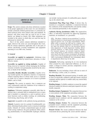
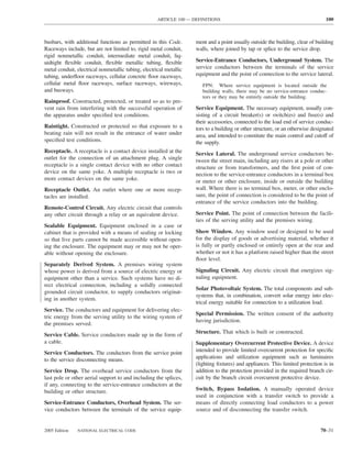
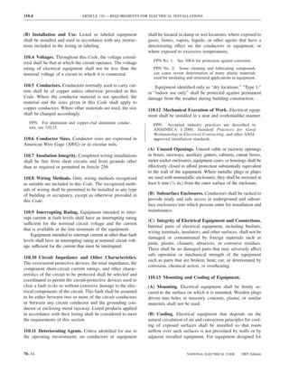
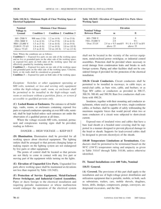
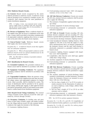
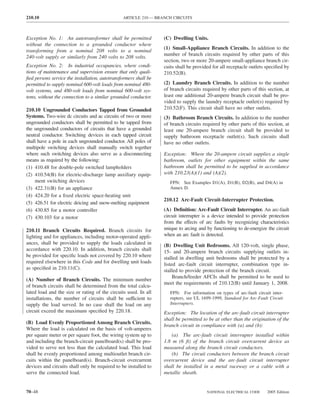
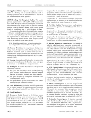
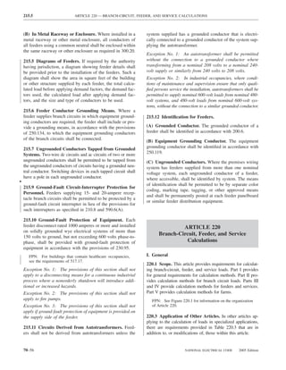
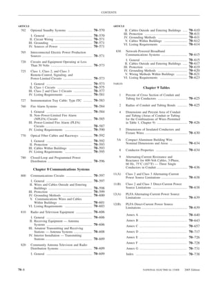
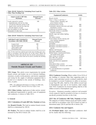
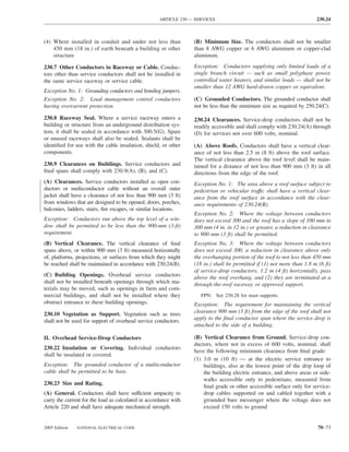
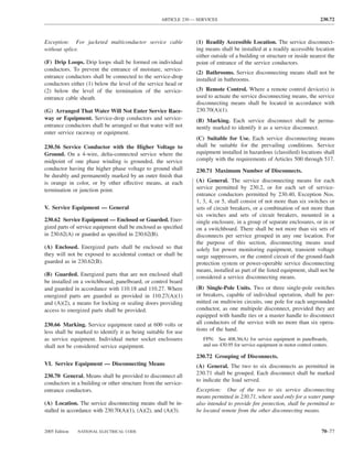
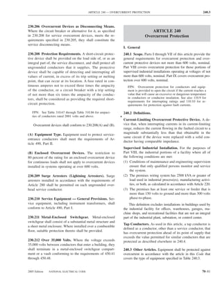
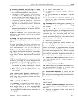
![220.14 ARTICLE 220 — BRANCH-CIRCUIT, FEEDER, AND SERVICE CALCULATIONS
lighting load. The floor area for each floor shall be calcu- Exception: The loads of outlets serving switchboards and
lated from the outside dimensions of the building, dwelling switching frames in telephone exchanges shall be waived
unit, or other area involved. For dwelling units, the calcu- from the calculations.
lated floor area shall not include open porches, garages, or
unused or unfinished spaces not adaptable for future use. (A) Specific Appliances or Loads. An outlet for a specific
appliance or other load not covered in 220.14(B) through
FPN: The unit values herein are based on minimum load
conditions and 100 percent power factor and may not pro- (L) shall be calculated based on the ampere rating of the
vide sufficient capacity for the installation contemplated. appliance or load served.
(B) Electric Dryers and Household Electric Cooking
Table 220.12 General Lighting Loads by Occupancy
Appliances. Load calculations shall be permitted as speci-
fied in 220.54 for electric dryers and in 220.55 for electric
Unit Load
ranges and other cooking appliances.
Volt-Amperes Volt-Amperes
per Square per Square (C) Motor Loads. Outlets for motor loads shall be calcu-
Type of Occupancy Meter Foot lated in accordance with the requirements in 430.22,
430.24, and 440.6.
Armories and auditoriums 11 1
Banks 39b 31⁄2b (D) Luminaires (Lighting Fixtures). An outlet supplying
Barber shops and beauty 33 3 luminaire(s) [lighting fixture(s)] shall be calculated based
parlors
Churches 11 1
on the maximum volt-ampere rating of the equipment and
Clubs 22 2 lamps for which the luminaire(s) [fixture(s)] is rated.
Court rooms 22 2
Dwelling unitsa 33 3 (E) Heavy-Duty Lampholders. Outlets for heavy-duty
Garages — commercial 6 1⁄2 lampholders shall be calculated at a minimum of 600 volt-
(storage) amperes.
Hospitals 22 2
Hotels and motels, including 22 2 (F) Sign and Outline Lighting. Sign and outline lighting
apartment houses without
outlets shall be calculated at a minimum of 1200 volt-
provision for cooking by
tenantsa amperes for each required branch circuit specified in
Industrial commercial (loft) 22 2 600.5(A).
buildings
Lodge rooms 17 11⁄2 (G) Show Windows. Show windows shall be calculated in
Office buildings 39b 31⁄2b accordance with either of the following:
Restaurants 22 2
Schools 33 3
(1) The unit load per outlet as required in other provisions
Stores 33 3 of this section
Warehouses (storage) 3 1⁄4
(2) At 200 volt-amperes per 300 mm (1 ft) of show
In any of the preceding window
occupancies except
one-family dwellings and (H) Fixed Multioutlet Assemblies. Fixed multioutlet as-
individual dwelling units of
two-family and multifamily semblies used in other than dwelling units or the guest
dwellings: rooms or guest suites of hotels or motels shall be calculated
Assembly halls and 11 1 in accordance with (H)(1) or (H)(2). For the purposes of
auditoriums this section, the calculation shall be permitted to be based
Halls, corridors, closets, 6 ⁄
12
on the portion that contains receptacle outlets.
stairways
Storage spaces 3 ⁄
14 (1) Where appliances are unlikely to be used simulta-
neously, each 1.5 m (5 ft) or fraction thereof of each
a
See 220.14(J). separate and continuous length shall be considered as
b
See 220.14(K). one outlet of not less than 180 volt-amperes.
(2) Where appliances are likely to be used simultaneously,
220.14 Other Loads — All Occupancies. In all occupan- each 300 mm (1 ft) or fraction thereof shall be consid-
cies, the minimum load for each outlet for general-use re- ered as an outlet of not less than 180 volt-amperes.
ceptacles and outlets not used for general illumination shall
not be less than that calculated in 220.14(A) through (L), (I) Receptacle Outlets. Except as covered in 220.14(J)
the loads shown being based on nominal branch-circuit and (K), receptacle outlets shall be calculated at not less
voltages. than 180 volt-amperes for each single or for each multiple
70–58 NATIONAL ELECTRICAL CODE 2005 Edition](https://image.slidesharecdn.com/nechandbookversin2005compacta-100921141249-phpapp02/85/Nec-handbook-version-2005-compacta-61-320.jpg)
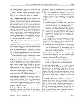
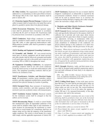
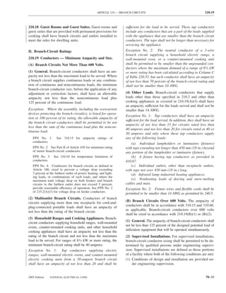
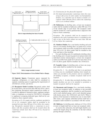
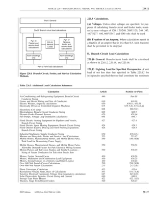
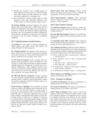
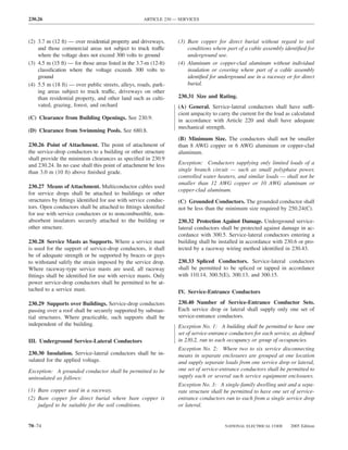
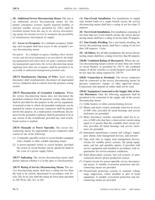
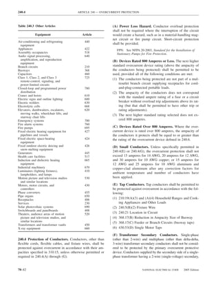
![ARTICLE 220 — BRANCH-CIRCUIT, FEEDER, AND SERVICE CALCULATIONS 220.80
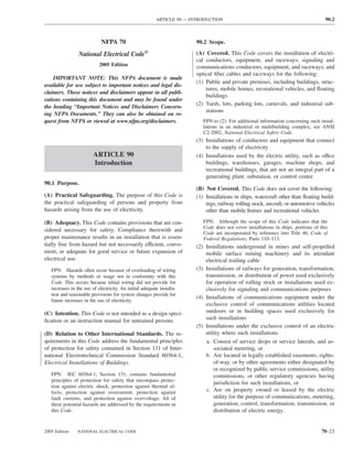
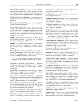
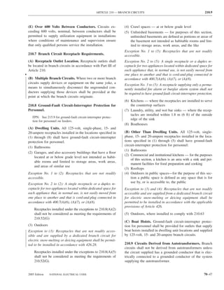
Table 220.54 Demand Factors for Household Electric 220.60 Noncoincident Loads. Where it is unlikely that
Clothes Dryers two or more noncoincident loads will be in use simulta-
neously, it shall be permissible to use only the largest
Number of Demand Factor load(s) that will be used at one time for calculating the total
Dryers (Percent) load of a feeder or service.
1–4 100%
5 85% 220.61 Feeder or Service Neutral Load.
6 75% (A) Basic Calculation. The feeder or service neutral load
7 65% shall be the maximum unbalance of the load determined by
8 60% this article. The maximum unbalanced load shall be the
9 55% maximum net calculated load between the neutral and any
10 50% one ungrounded conductor.
11 47%
12–22 % = 47 – (number of dryers − 11) Exception: For 3-wire, 2-phase or 5-wire, 2-phase sys-
tems, the maximum unbalanced load shall be the maximum
23 35% net calculated load between the neutral and any one un-
grounded conductor multiplied by 140 percent.
24–42 % = 35 – [0.5 × (number of dryers − 23)]
(B) Permitted Reductions. A service or feeder supplying
43 and over 25%
the following loads shall be permitted to have an additional
demand factor of 70 percent applied to the amount in
220.61(B)(1) or portion of the amount in 220.61(B)(2) de-
FPN No. 1: See Example D5(A) in Annex D.
termined by the basic calculation:
FPN No. 2: See Table 220.56 for commercial cooking (1) A feeder or service supplying household electric
equipment. ranges, wall-mounted ovens, counter-mounted cooking
FPN No. 3: See the examples in Annex D. units, and electric dryers, where the maximum unbal-
anced load has been determined in accordance with
220.56 Kitchen Equipment — Other Than Dwelling Table 220.55 for ranges and Table 220.54 for dryers
Unit(s). It shall be permissible to calculate the load for (2) That portion of the unbalanced load in excess of 200 am-
commercial electric cooking equipment, dishwasher peres where the feeder or service is supplied from a
booster heaters, water heaters, and other kitchen equipment 3-wire dc or single-phase ac system, or a 4-wire, 3-phase;
in accordance with Table 220.56. These demand factors 3-wire, 2-phase system, or a 5-wire, 2-phase system
shall be applied to all equipment that has either thermo-
static control or intermittent use as kitchen equipment. (C) Prohibited Reductions. There shall be no reduction of
These demand factors shall not apply to space-heating, ven- the neutral or grounded conductor capacity applied to the
amount in 220.61(C)(1), or portion of the amount in (C)(2),
tilating, or air-conditioning equipment.
from that determined by the basic calculation:
However, in no case shall the feeder or service calcu-
lated load be less than the sum of the largest two kitchen (1) Any portion of a 3-wire circuit consisting of 2-phase
equipment loads. wires and the neutral of a 4-wire, 3-phase, wye-
connected system
(2) That portion consisting of nonlinear loads supplied
from a 4-wire, wye-connected, 3-phase system
Table 220.56 Demand Factors for Kitchen Equipment —
Other Than Dwelling Unit(s) FPN No. 1: See Examples D1(A), D1(B), D2(B), D4(A),
and D5(A) in Annex D.
Number of Units of Demand Factor
Equipment (Percent) FPN No. 2: A 3-phase, 4-wire, wye-connected power sys-
tem used to supply power to nonlinear loads may necessi-
tate that the power system design allow for the possibility
1 100 of high harmonic neutral currents.
2 100
3 90
4 80 IV. Optional Feeder and Service Load Calculations
5 70
6 and over 65 220.80 General. Optional feeder and service load calcula-
tions shall be permitted in accordance with Part IV.
2005 Edition NATIONAL ELECTRICAL CODE 70–61](https://image.slidesharecdn.com/nechandbookversin2005compacta-100921141249-phpapp02/85/Nec-handbook-version-2005-compacta-64-320.jpg)
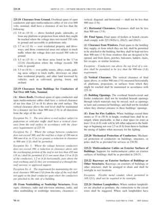

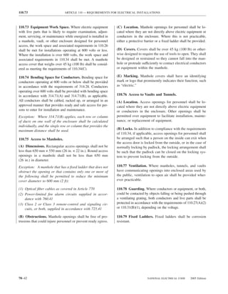
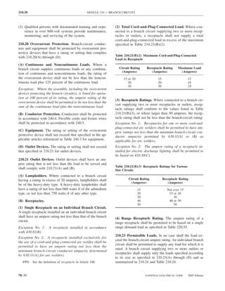
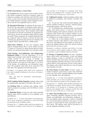
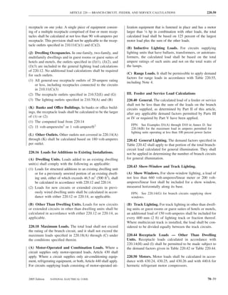
![ARTICLE 240 — OVERCURRENT PROTECTION 240.21
(A) Branch-Circuit Conductors. Branch-circuit tap con- (3) Taps Supplying a Transformer [Primary Plus Sec-
ductors meeting the requirements specified in 210.19 shall ondary Not Over 7.5 m (25 ft) Long]. Where the tap
be permitted to have overcurrent protection located as conductors supply a transformer and comply with all the
specified in that section. following conditions:
(1) The conductors supplying the primary of a transformer
(B) Feeder Taps. Conductors shall be permitted to be have an ampacity at least one-third the rating of the
tapped, without overcurrent protection at the tap, to a feeder as overcurrent device protecting the feeder conductors.
specified in 240.21(B)(1) through (B)(5). The provisions of (2) The conductors supplied by the secondary of the trans-
240.4(B) shall not be permitted for tap conductors. former shall have an ampacity that is not less than the
value of the primary-to-secondary voltage ratio multi-
(1) Taps Not Over 3 m (10 ft) Long. Where the length of plied by one-third of the rating of the overcurrent de-
the tap conductors does not exceed 3 m (10 ft) and the tap vice protecting the feeder conductors.
conductors comply with all of the following: (3) The total length of one primary plus one secondary con-
(1) The ampacity of the tap conductors is ductor, excluding any portion of the primary conductor
that is protected at its ampacity, is not over 7.5 m (25 ft).
a. Not less than the combined calculated loads on the
circuits supplied by the tap conductors, and (4) The primary and secondary conductors are protected
from physical damage by being enclosed in an ap-
b. Not less than the rating of the device supplied by
proved raceway or by other approved means.
the tap conductors or not less than the rating of the
overcurrent-protective device at the termination of (5) The secondary conductors terminate in a single circuit
the tap conductors. breaker or set of fuses that limit the load current to not
more than the conductor ampacity that is permitted by
(2) The tap conductors do not extend beyond the switch- 310.15.
board, panelboard, disconnecting means, or control de-
(4) Taps Over 7.5 m (25 ft) Long. Where the feeder is in
vices they supply.
a high bay manufacturing building over 11 m (35 ft) high at
(3) Except at the point of connection to the feeder, the tap walls and the installation complies with all the following
conductors are enclosed in a raceway, which shall ex- conditions:
tend from the tap to the enclosure of an enclosed (1) Conditions of maintenance and supervision ensure that
switchboard, panelboard, or control devices, or to the only qualified persons service the systems.
back of an open switchboard. (2) The tap conductors are not over 7.5 m (25 ft) long
(4) For field installations where the tap conductors leave horizontally and not over 30 m (100 ft) total length.
the enclosure or vault in which the tap is made, the (3) The ampacity of the tap conductors is not less than
rating of the overcurrent device on the line side of the one-third the rating of the overcurrent device protecting
tap conductors shall not exceed 10 times the ampacity the feeder conductors.
of the tap conductor. (4) The tap conductors terminate at a single circuit breaker
or a single set of fuses that limit the load to the ampac-
FPN: For overcurrent protection requirements for lighting
and appliance branch-circuit panelboards and certain power ity of the tap conductors. This single overcurrent de-
panelboards, see 408.36(A), (B), and (E). vice shall be permitted to supply any number of addi-
tional overcurrent devices on its load side.
(2) Taps Not Over 7.5 m (25 ft) Long. Where the length (5) The tap conductors are protected from physical damage
of the tap conductors does not exceed 7.5 m (25 ft) and the by being enclosed in an approved raceway or by other
tap conductors comply with all the following: approved means.
(1) The ampacity of the tap conductors is not less than (6) The tap conductors are continuous from end-to-end and
one-third of the rating of the overcurrent device pro- contain no splices.
tecting the feeder conductors. (7) The tap conductors are sized 6 AWG copper or 4 AWG
(2) The tap conductors terminate in a single circuit breaker aluminum or larger.
or a single set of fuses that will limit the load to the (8) The tap conductors do not penetrate walls, floors, or
ampacity of the tap conductors. This device shall be ceilings.
permitted to supply any number of additional overcur- (9) The tap is made no less than 9 m (30 ft) from the floor.
rent devices on its load side. (5) Outside Taps of Unlimited Length. Where the con-
(3) The tap conductors are protected from physical damage ductors are located outdoors of a building or structure, ex-
by being enclosed in an approved raceway or by other cept at the point of load termination, and comply with all of
approved means. the following conditions:
2005 Edition NATIONAL ELECTRICAL CODE 70–85](https://image.slidesharecdn.com/nechandbookversin2005compacta-100921141249-phpapp02/85/Nec-handbook-version-2005-compacta-88-320.jpg)
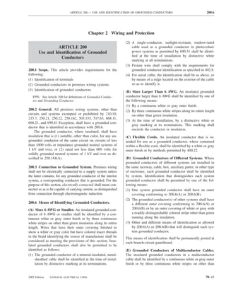
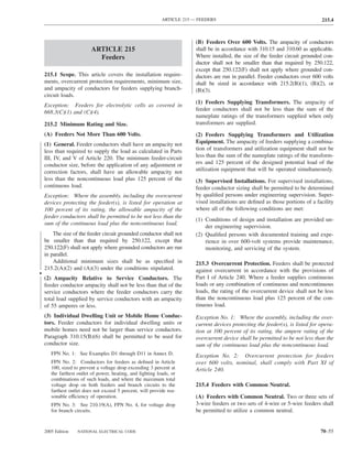
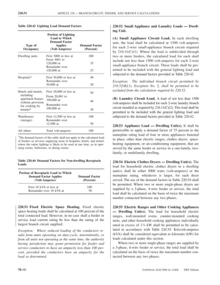
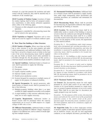
![240.86 ARTICLE 240 — OVERCURRENT PROTECTION
of the circuit breaker’s voltage rating and the nominal volt- (A) Feeder and Branch-Circuit Conductors. Feeder and
age between any two conductors does not exceed the higher branch-circuit conductors shall be protected at the point the
value of the circuit breaker’s voltage rating. conductors receive their supply as permitted in 240.21 or as
otherwise permitted in 240.92(B), (C), or (D).
FPN: Proper application of molded case circuit breakers
on 3-phase systems, other than solidly grounded wye, par- (B) Transformer Secondary Conductors of Separately
ticularly on corner grounded delta systems, considers the Derived Systems. Conductors shall be permitted to be con-
circuit breakers’ individual pole-interrupting capability. nected to a transformer secondary of a separately derived sys-
tem, without overcurrent protection at the connection, where
240.86 Series Ratings. Where a circuit breaker is used on the conditions of 240.92(B)(1), (B)(2), and (B)(3) are met.
a circuit having an available fault current higher than the
marked interrupting rating by being connected on the load (1) Short-Circuit and Ground-Fault Protection. The con-
side of an acceptable overcurrent protective device having a ductors shall be protected from short-circuit and ground-fault
conditions by complying with one of the following conditions:
higher rating, the circuit breaker shall meet the require-
ments specified in (A) or (B), and (C). (1) The length of the secondary conductors does not ex-
ceed 30 m (100 ft) and the transformer primary over-
(A) Selected Under Engineering Supervision in Existing current device has a rating or setting that does not
Installations. The series rated combination devices shall be exceed 150 percent of the value determined by mul-
selected by a licensed professional engineer engaged pri- tiplying the secondary conductor ampacity by the
marily in the design or maintenance of electrical installa- secondary-to-primary transformer voltage ratio.
tions. The selection shall be documented and stamped by (2) The conductors are protected by a differential relay
the professional engineer. This documentation shall be with a trip setting equal to or less than the conductor
available to those authorized to design, install, inspect, ampacity.
maintain, and operate the system. This series combination FPN: A differential relay is connected to be sensitive only
rating, including identification of the upstream device, shall to short-circuit or fault currents within the protected zone
be field marked on the end use equipment. and is normally set much lower than the conductor ampac-
ity. The differential relay is connected to trip protective
(B) Tested Combinations. The combination of line-side devices that will de-energize the protected conductors if a
short-circuit condition occurs.
overcurrent device and load-side circuit breaker(s) is tested
and marked on the end use equipment, such as switch- (3) The conductors shall be considered to be protected if
boards and panelboards. calculations, made under engineering supervision, de-
termine that the system overcurrent devices will protect
(C) Motor Contribution. Series ratings shall not be used the conductors within recognized time vs. current limits
where for all short-circuit and ground-fault conditions.
(1) Motors are connected on the load side of the higher- (2) Overload Protection. The conductors shall be pro-
rated overcurrent device and on the line side of the tected against overload conditions by complying with one
lower-rated overcurrent device, and of the following:
(2) The sum of the motor full-load currents exceeds 1 per- (1) The conductors terminate in a single overcurrent device
cent of the interrupting rating of the lower-rated circuit that will limit the load to the conductor ampacity.
breaker. (2) The sum of the overcurrent devices at the conductor
termination limits the load to the conductor ampacity.
VIII. Supervised Industrial Installations The overcurrent devices shall consist of not more than
six circuit breakers or sets of fuses, mounted in a single
240.90 General. Overcurrent protection in areas of super- enclosure, in a group of separate enclosures, or in or on
vised industrial installations shall comply with all of the a switchboard. There shall be no more than six over-
other applicable provisions of this article, except as pro- current devices grouped in any one location.
vided in Part VIII. The provisions of Part VIII shall be (3) Overcurrent relaying is connected [with a current trans-
permitted only to apply to those portions of the electrical former(s), if needed] to sense all of the secondary con-
system in the supervised industrial installation used exclu- ductor current and limit the load to the conductor am-
sively for manufacturing or process control activities. pacity by opening upstream or downstream devices.
(4) Conductors shall be considered to be protected if cal-
240.92 Location in Circuit. An overcurrent device shall culations, made under engineering supervision, deter-
be connected in each ungrounded circuit conductor as re- mine that the system overcurrent devices will protect
quired in 240.92(A) through (D). the conductors from overload conditions.
70–90 NATIONAL ELECTRICAL CODE 2005 Edition](https://image.slidesharecdn.com/nechandbookversin2005compacta-100921141249-phpapp02/85/Nec-handbook-version-2005-compacta-93-320.jpg)
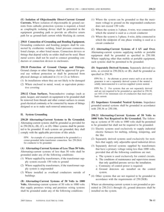
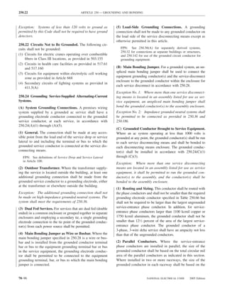
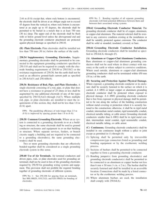
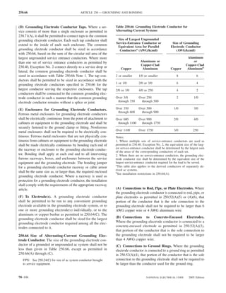
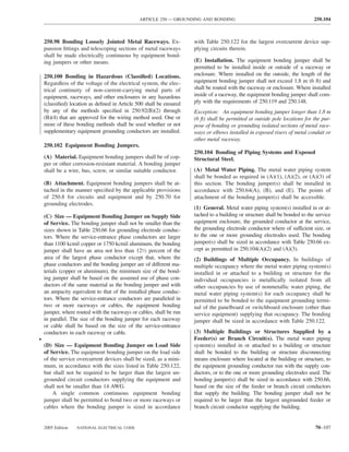
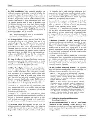
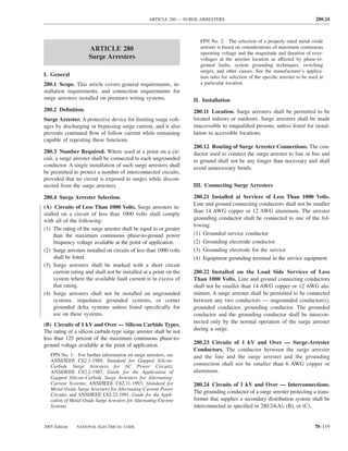
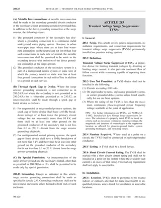
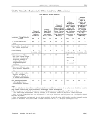
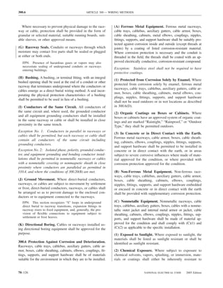
![ARTICLE 300 — WIRING METHODS 300.11
chemicals based on its listing or be identified for the spe- enclosures for conductors shall be metallically joined together
cific chemical reagent. into a continuous electric conductor and shall be connected to
all boxes, fittings, and cabinets so as to provide effective elec-
(D) Indoor Wet Locations. In portions of dairy processing
trical continuity. Unless specifically permitted elsewhere in
facilities, laundries, canneries, and other indoor wet loca-
this Code, raceways and cable assemblies shall be mechani-
tions, and in locations where walls are frequently washed or
cally secured to boxes, fittings, cabinets, and other enclosures.
where there are surfaces of absorbent materials, such as
damp paper or wood, the entire wiring system, where in- Exception No. 1: Short sections of raceways used to pro-
stalled exposed, including all boxes, fittings, raceways, and vide support or protection of cable assemblies from physi-
cable used therewith, shall be mounted so that there is at cal damage shall not be required to be made electrically
least a 6-mm (1⁄4-in.) airspace between it and the wall or continuous.
supporting surface.
Exception No. 2: Equipment enclosures to be isolated, as
Exception: Nonmetallic raceways, boxes, and fittings shall permitted by 250.96(B), shall not be required to be metal-
be permitted to be installed without the airspace on a con- lically joined to the metal raceway.
crete, masonry, tile, or similar surface.
FPN: In general, areas where acids and alkali chemicals
300.11 Securing and Supporting.
are handled and stored may present such corrosive condi-
(A) Secured in Place. Raceways, cable assemblies, boxes,
tions, particularly when wet or damp. Severe corrosive con-
ditions may also be present in portions of meatpacking cabinets, and fittings shall be securely fastened in place.
plants, tanneries, glue houses, and some stables; in instal- Support wires that do not provide secure support shall not
lations immediately adjacent to a seashore and swimming be permitted as the sole support. Support wires and associ-
pool areas; in areas where chemical deicers are used; and in
ated fittings that provide secure support and that are in-
storage cellars or rooms for hides, casings, fertilizer, salt,
and bulk chemicals. stalled in addition to the ceiling grid support wires shall be
permitted as the sole support. Where independent support
300.7 Raceways Exposed to Different Temperatures. wires are used, they shall be secured at both ends. Cables
and raceways shall not be supported by ceiling grids.
(A) Sealing. Where portions of a cable raceway or sleeve
are known to be subjected to different temperatures and (1) Fire-Rated Assemblies. Wiring located within the cav-
where condensation is known to be a problem, as in cold ity of a fire-rated floor–ceiling or roof–ceiling assembly
storage areas of buildings or where passing from the inte- shall not be secured to, or supported by, the ceiling assem-
rior to the exterior of a building, the raceway or sleeve shall bly, including the ceiling support wires. An independent
be filled with an approved material to prevent the circula- means of secure support shall be provided and shall be
tion of warm air to a colder section of the raceway or permitted to be attached to the assembly. Where indepen-
sleeve. An explosionproof seal shall not be required for this dent support wires are used, they shall be distinguishable
purpose.
by color, tagging, or other effective means from those that
(B) Expansion Fittings. Raceways shall be provided with are part of the fire-rated design.
expansion fittings where necessary to compensate for ther- Exception: The ceiling support system shall be permitted
mal expansion and contraction. to support wiring and equipment that have been tested as
FPN: Table 352.44(A) provides the expansion information part of the fire-rated assembly.
for polyvinyl chloride (PVC). A nominal number for steel
conduit can be determined by multiplying the expansion FPN: One method of determining fire rating is testing in
length in this table by 0.20. The coefficient of expansion for accordance with NFPA 251-1999, Standard Methods of
steel electrical metallic tubing, intermediate metal conduit, Tests of Fire Endurance of Building Construction and
and rigid conduit is 11.70 × 10⁻⁶ (0.0000117 mm per mm Materials.
of conduit for each °C in temperature change) [6.50 × 10⁻⁶
(0.0000065 in. per inch of conduit for each °F in tempera- (2) Non–Fire-Rated Assemblies. Wiring located within
ture change)]. the cavity of a non–fire-rated floor–ceiling or roof–ceiling
assembly shall not be secured to, or supported by, the ceil-
300.8 Installation of Conductors with Other Systems. ing assembly, including the ceiling support wires. An inde-
Raceways or cable trays containing electric conductors pendent means of secure support shall be provided.
shall not contain any pipe, tube, or equal for steam, water,
air, gas, drainage, or any service other than electrical. Exception: The ceiling support system shall be permitted
to support branch-circuit wiring and associated equipment
300.10 Electrical Continuity of Metal Raceways and where installed in accordance with the ceiling system
Enclosures. Metal raceways, cable armor, and other metal manufacturer’s instructions.
2005 Edition NATIONAL ELECTRICAL CODE 70–127](https://image.slidesharecdn.com/nechandbookversin2005compacta-100921141249-phpapp02/85/Nec-handbook-version-2005-compacta-130-320.jpg)
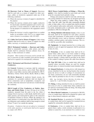
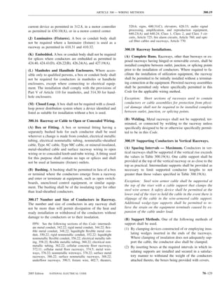
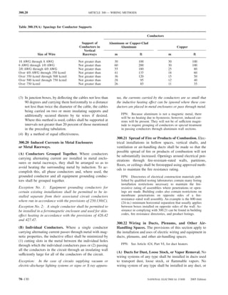
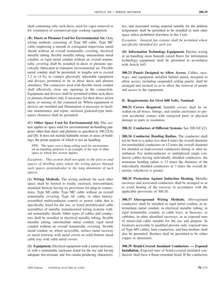
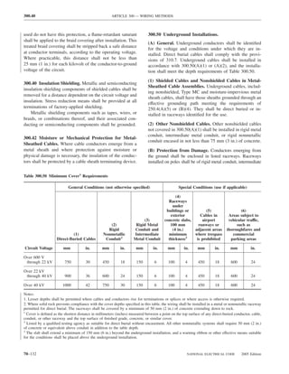
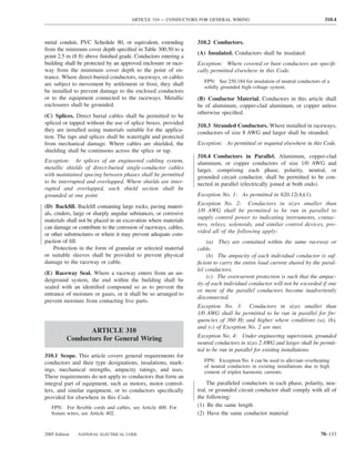
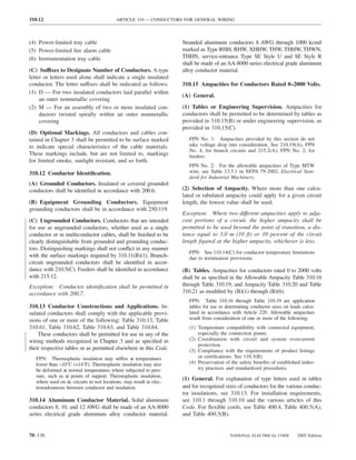
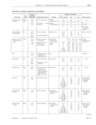
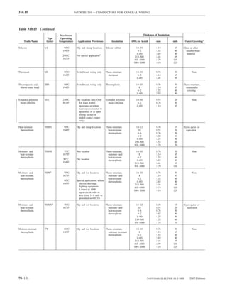
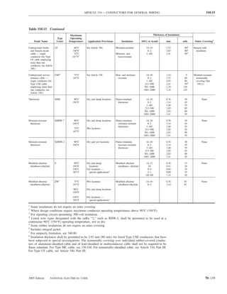

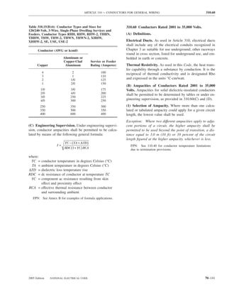
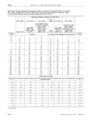
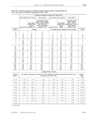
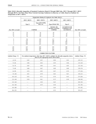
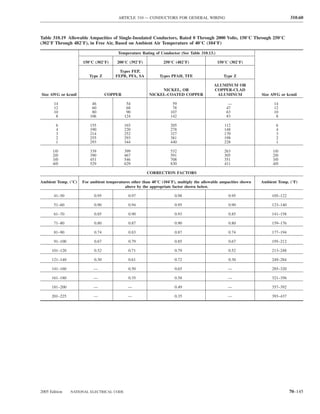
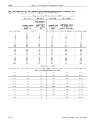
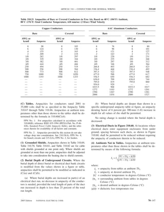
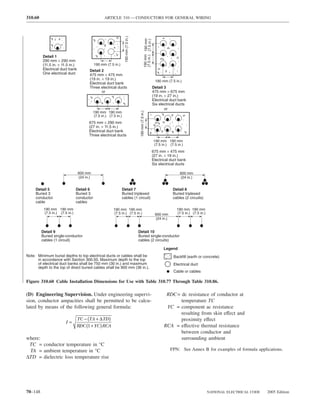
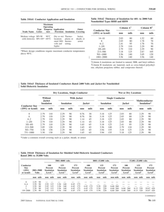
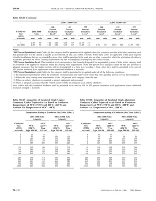
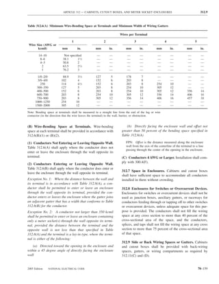
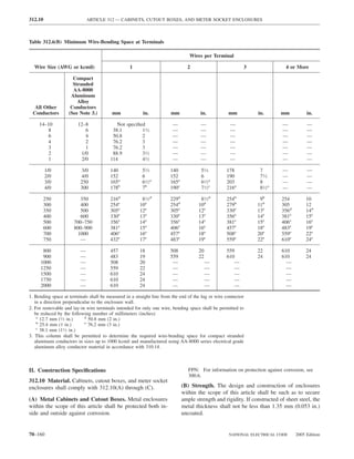
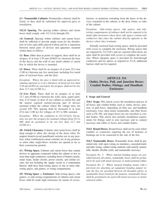
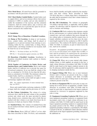
![ARTICLE 314 — OUTLET, DEVICE, PULL, AND JUNCTION BOXES; CONDUIT BODIES; FITTINGS; AND HANDHOLES 314.23
thereto by clamps, anchors, or fittings identified for the size, including a conduit body constructed with only one
application. conduit entry, provided the trade size of the conduit body is
not larger than the largest trade size of the conduit.
(D) Suspended Ceilings. An enclosure mounted to struc-
tural or supporting elements of a suspended ceiling shall be Exception No. 2: An unbroken length(s) of rigid or interme-
not more than 1650 cm3 (100 in.3) in size and shall be diate metal conduit shall be permitted to support a box used
securely fastened in place in accordance with either (D)(1) for luminaire (fixture) or lampholder support, or to support a
or (D)(2). wiring enclosure that is an integral part of a luminaire (fix-
ture) and used in lieu of a box in accordance with 300.15(B),
(1) Framing Members. An enclosure shall be fastened to
where all of the following conditions are met:
the framing members by mechanical means such as bolts,
screws, or rivets, or by the use of clips or other securing (a) The conduit is securely fastened at a point so that
means identified for use with the type of ceiling framing the length of conduit beyond the last point of conduit sup-
member(s) and enclosure(s) employed. The framing mem- port does not exceed 900 mm (3 ft).
bers shall be adequately supported and securely fastened to (b) The unbroken conduit length before the last point
each other and to the building structure. of conduit support is 300 mm (12 in.) or greater, and that
portion of the conduit is securely fastened at some point not
(2) Support Wires. The installation shall comply with the
provisions of 300.11(A). The enclosure shall be secured, less than 300 mm (12 in.) from its last point of support.
using methods identified for the purpose, to ceiling support (c) Where accessible to unqualified persons, the lumi-
wire(s), including any additional support wire(s) installed naire (fixture) or lampholder, measured to its lowest point,
for that purpose. Support wire(s) used for enclosure support is at least 2.5 m (8 ft) above grade or standing area and at
shall be fastened at each end so as to be taut within the least 900 mm (3 ft) measured horizontally to the 2.5 m (8 ft)
ceiling cavity. elevation from windows, doors, porches, fire escapes, or
similar locations.
(E) Raceway Supported Enclosure, Without Devices, (d) A luminaire (fixture) supported by a single conduit
Luminaires (Fixtures), or Lampholders. An enclosure does not exceed 300 mm (12 in.) in any direction from the
that does not contain a device(s) other than splicing devices point of conduit entry.
or support a luminaire(s) [fixture(s)], lampholder, or other (e) The weight supported by any single conduit does
equipment and is supported by entering raceways shall not not exceed 9 kg (20 lb).
exceed 1650 cm3 (100 in.3) in size. It shall have threaded (f) At the luminaire (fixture) or lampholder end, the
entries or have hubs identified for the purpose. It shall be
conduit(s) is threaded wrenchtight into the box, conduit
supported by two or more conduits threaded wrenchtight
body, or integral wiring enclosure, or into hubs identified
into the enclosure or hubs. Each conduit shall be secured
for the purpose. Where a box or conduit body is used for
within 900 mm (3 ft) of the enclosure, or within 450 mm
support, the luminaire (fixture) shall be secured directly to
(18 in.) of the enclosure if all conduit entries are on the
the box or conduit body, or through a threaded conduit
same side.
nipple not over 75 mm (3 in.) long.
Exception: Rigid metal, intermediate metal, or rigid nonme-
tallic conduit or electrical metallic tubing shall be permitted (G) Enclosures in Concrete or Masonry. An enclosure
to support a conduit body of any size, including a conduit supported by embedment shall be identified as suitably pro-
body constructed with only one conduit entry, provided the tected from corrosion and securely embedded in concrete or
trade size of the conduit body is not larger than the largest masonry.
trade size of the conduit or electrical metallic tubing.
(H) Pendant Boxes. An enclosure supported by a pendant
(F) Raceway Supported Enclosures, with Devices, Lu- shall comply with 314.23(H)(1) or (H)(2).
minaires (Fixtures), or Lampholders. An enclosure that
contains a device(s), other than splicing devices, or supports a (1) Flexible Cord. A box shall be supported from a mul-
luminaire(s) [fixture(s)], lampholder, or other equipment and ticonductor cord or cable in an approved manner that pro-
is supported by entering raceways shall not exceed 1650 cm3 tects the conductors against strain, such as a strain-relief
(100 in.3) in size. It shall have threaded entries or have hubs connector threaded into a box with a hub.
identified for the purpose. It shall be supported by two or more (2) Conduit. A box supporting lampholders or luminaires
conduits threaded wrenchtight into the enclosure or hubs. (lighting fixtures), or wiring enclosures within luminaires
Each conduit shall be secured within 450 mm (18 in.) of the (fixtures) used in lieu of boxes in accordance with
enclosure. 300.15(B), shall be supported by rigid or intermediate
Exception No. 1: Rigid metal or intermediate metal con- metal conduit stems. For stems longer than 450 mm
duit shall be permitted to support a conduit body of any (18 in.), the stems shall be connected to the wiring system
2005 Edition NATIONAL ELECTRICAL CODE 70–165](https://image.slidesharecdn.com/nechandbookversin2005compacta-100921141249-phpapp02/85/Nec-handbook-version-2005-compacta-168-320.jpg)
![320.40 ARTICLE 322 — FLAT CABLE ASSEMBLIES: TYPE FC
(B) Securing. Unless otherwise provided, Type AC cable III. Construction Specifications
shall be secured within 300 mm (12 in.) of every outlet
box, junction box, cabinet, or fitting and at intervals not 320.100 Construction. Type AC cable shall have an armor
exceeding 1.4 m (41⁄2 ft) where installed on or across fram- of flexible metal tape and shall have an internal bonding
ing members. strip of copper or aluminum in intimate contact with the
armor for its entire length.
(C) Supporting. Unless otherwise provided, Type AC cable
shall be supported at intervals not exceeding 1.4 m (41⁄2 ft). 320.104 Conductors. Insulated conductors shall be of a
Horizontal runs of Type AC cable installed in wooden type listed in Table 310.13 or those identified for use in this
or metal framing members or similar supporting means cable. In addition, the conductors shall have an overall
shall be considered supported where such support does not moisture-resistant and fire-retardant fibrous covering. For
exceed 1.4-m (41⁄2-ft) intervals. Type ACT, a moisture-resistant fibrous covering shall be
(D) Unsupported Cables. Type AC cable shall be permit- required only on the individual conductors.
ted to be unsupported where the cable complies with any of
the following: 320.108 Equipment Grounding. Type AC cable shall pro-
(1) Is fished between access points through concealed vide an adequate path for equipment grounding as required
spaces in finished buildings or structures and support- by 250.4(A)(5) or 250.4(B)(4).
ing is impracticable
(2) Is not more than 600 mm (2 ft) in length at terminals 320.120 Marking. The cable shall be marked in accor-
where flexibility is necessary dance with 310.11, except that Type AC shall have ready
(3) Is not more than 1.8 m (6 ft) in length from the last identification of the manufacturer by distinctive external
point of cable support to the point of connection to a markings on the cable sheath throughout its entire length.
luminaire(s) [lighting fixture(s)] or other electrical
equipment and the cable and point of connection are
within an accessible ceiling. For the purposes of this
section, Type AC cable fittings shall be permitted as a
ARTICLE 322
means of cable support.
Flat Cable Assemblies: Type FC
320.40 Boxes and Fittings. At all points where the armor
of AC cable terminates, a fitting shall be provided to protect
I. General
wires from abrasion, unless the design of the outlet boxes
or fittings is such as to afford equivalent protection, and, in 322.1 Scope. This article covers the use, installation, and
addition, an insulating bushing or its equivalent protection construction specifications for flat cable assemblies, Type FC.
shall be provided between the conductors and the armor.
The connector or clamp by which the Type AC cable is
322.2 Definition.
fastened to boxes or cabinets shall be of such design that
the insulating bushing or its equivalent will be visible for Flat Cable Assembly, Type FC. An assembly of parallel
inspection. Where change is made from Type AC cable to conductors formed integrally with an insulating material
other cable or raceway wiring methods, a box, fitting, or web specifically designed for field installation in surface
conduit body shall be installed at junction points as re- metal raceway.
quired in 300.15.
320.80 Ampacity. The ampacity shall be determined by II. Installation
310.15.
322.10 Uses Permitted. Flat cable assemblies shall be per-
(A) Thermal Insulation. Armored cable installed in ther- mitted only as follows:
mal insulation shall have conductors rated at 90°C (194°F). (1) As branch circuits to supply suitable tap devices for light-
The ampacity of cable installed in these applications shall ing, small appliances, or small power loads. The rating of
be that of 60°C (140°F) conductors. The 90°C (194°F) rat- the branch circuit shall not exceed 30 amperes.
ing shall be permitted to be used for ampacity derating
(2) Where installed for exposed work.
purposes, provided the final derated ampacity does not ex-
ceed that for a 60°C (140°F) rated conductor. (3) In locations where they will not be subjected to physical
damage. Where a flat cable assembly is installed less than
(B) Cable Tray. The ampacity of Type AC cable installed in 2.5 m (8 ft) above the floor or fixed working platform, it
cable tray shall be determined in accordance with 392.11. shall be protected by a cover identified for the use.
70–170 NATIONAL ELECTRICAL CODE 2005 Edition](https://image.slidesharecdn.com/nechandbookversin2005compacta-100921141249-phpapp02/85/Nec-handbook-version-2005-compacta-173-320.jpg)
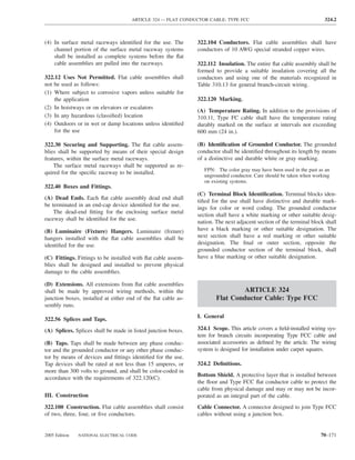
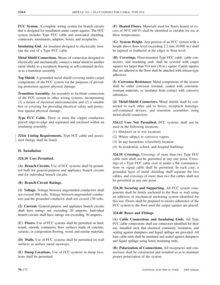
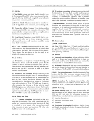
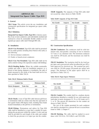
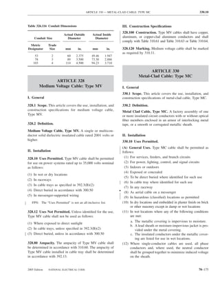
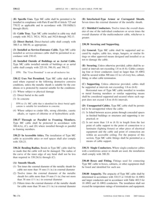
![ARTICLE 334 — NONMETALLIC-SHEATHED CABLE: TYPES NM, NMC, AND NMS 334.15
II. Installation (2) Exposed in dropped or suspended ceilings in other
than one- and two-family and multifamily dwellings
334.10 Uses Permitted. Type NM, Type NMC, and
Type NMS cables shall be permitted to be used in the (3) As service-entrance cable
following: (4) In commercial garages having hazardous (classified)
(1) One- and two-family dwellings. locations as defined in 511.3
(2) Multifamily dwellings permitted to be of Types III, IV, (5) In theaters and similar locations, except where permit-
and V construction except as prohibited in 334.12. ted in 518.4(B)
(3) Other structures permitted to be of Types III, IV, and V (6) In motion picture studios
construction except as prohibited in 334.12. Cables (7) In storage battery rooms
shall be concealed within walls, floors, or ceilings that (8) In hoistways or on elevators or escalators
provide a thermal barrier of material that has at least a (9) Embedded in poured cement, concrete, or aggregate
15-minute finish rating as identified in listings of fire- (10) In hazardous (classified) locations, except where per-
rated assemblies. mitted by the following:
FPN No. 1: Types of building construction and occupancy a. 501.10(B)(3)
classifications are defined in NFPA 220-1999, Standard on b. 502.10(B)(3)
Types of Building Construction, or the applicable building
c. 504.20
code, or both.
FPN No. 2: See Annex E for determination of building (B) Types NM and NMS. Types NM and NMS cables
types [NFPA 220, Table 3-1]. shall not be used under the following conditions or in the
(4) Cable trays in structures permitted to be Types III, IV, following locations:
or V where the cables are identified for the use. (1) Where exposed to corrosive fumes or vapors
FPN: See 310.10 for temperature limitation of conductors. (2) Where embedded in masonry, concrete, adobe, fill, or
plaster
(A) Type NM. Type NM cable shall be permitted as follows:
(3) In a shallow chase in masonry, concrete, or adobe and
(1) For both exposed and concealed work in normally dry covered with plaster, adobe, or similar finish
locations except as prohibited in 334.10(3)
(4) Where exposed or subject to excessive moisture or
(2) To be installed or fished in air voids in masonry block dampness
or tile walls
(B) Type NMC. Type NMC cable shall be permitted as 334.15 Exposed Work. In exposed work, except as pro-
follows: vided in 300.11(A), cable shall be installed as specified in
334.15(A) through (C).
(1) For both exposed and concealed work in dry, moist,
damp, or corrosive locations, except as prohibited by (A) To Follow Surface. Cable shall closely follow the sur-
334.10(3) face of the building finish or of running boards.
(2) In outside and inside walls of masonry block or tile
(3) In a shallow chase in masonry, concrete, or adobe pro- (B) Protection from Physical Damage. Cable shall be
tected against nails or screws by a steel plate at least protected from physical damage where necessary by rigid
1.59 mm (1⁄16 in.) thick and covered with plaster, adobe, metal conduit, intermediate metal conduit, electrical metal-
or similar finish lic tubing, Schedule 80 PVC rigid nonmetallic conduit, or
other approved means. Where passing through a floor, the
(C) Type NMS. Type NMS cable shall be permitted as cable shall be enclosed in rigid metal conduit, intermediate
follows: metal conduit, electrical metallic tubing, Schedule 80 PVC
(1) For both exposed and concealed work in normally dry rigid nonmetallic conduit, or other approved means extend-
locations except as prohibited by 334.10(3) ing at least 150 mm (6 in.) above the floor.
(2) To be installed or fished in air voids in masonry block Where Type NMC cable is installed in shallow chases
or tile walls in masonry, concrete, or adobe, the cable shall be protected
• against nails or screws by a steel plate at least 1.59 mm
334.12 Uses Not Permitted. (1⁄16 in.) thick and covered with plaster, adobe, or similar
finish.
(A) Types NM, NMC, and NMS. Types NM, NMC, and
NMS cables shall not be permitted as follows: (C) In Unfinished Basements. Where cable is run at
(1) In any dwelling or structure not specifically permitted angles with joists in unfinished basements, it shall be per-
in 334.10(1), (2), and (3) missible to secure cables not smaller than two 6 AWG or
2005 Edition NATIONAL ELECTRICAL CODE 70–179](https://image.slidesharecdn.com/nechandbookversin2005compacta-100921141249-phpapp02/85/Nec-handbook-version-2005-compacta-182-320.jpg)
![348.22 ARTICLE 348 — FLEXIBLE METAL CONDUIT: TYPE FMC
348.22 Number of Conductors. The number of conduc- (1) 900 mm (3 ft) for metric designators 16 through 35
tors shall not exceed that permitted by the percentage fill (trade sizes 1⁄2 through 11⁄4)
specified in Table 1, Chapter 9, or as permitted in Table (2) 1200 mm (4 ft) for metric designators 41 through 53
348.22, or for metric designator 12 (trade size 3⁄8). (trade sizes 11⁄2 through 2)
Cables shall be permitted to be installed where such use
(3) 1500 mm (5 ft) for metric designators 63 (trade size
is not prohibited by the respective cable articles. The num-
21⁄2) and larger
ber of cables shall not exceed the allowable percentage fill
specified in Table 1, Chapter 9. Exception No. 3: Lengths not exceeding 1.8 m (6 ft) from a
luminaire (fixture) terminal connection for tap connections to
348.24 Bends — How Made. Bends in conduit shall be luminaires (light fixtures) as permitted in 410.67(C).
made so that the conduit is not damaged and the internal
diameter of the conduit is not effectively reduced. Bends Exception No. 4: Lengths not exceeding 1.8 m (6 ft) from
shall be permitted to be made manually without auxiliary the last point where the raceway is securely fastened for
equipment. The radius of the curve to the centerline of any connections within an accessible ceiling to luminaire(s)
bend shall not be less than shown in Table 2, Chapter 9 [lighting fixture(s)] or other equipment.
using the column “Other Bends.”
(B) Supports. Horizontal runs of FMC supported by open-
348.26 Bends — Number in One Run. There shall not be ings through framing members at intervals not greater than
more than the equivalent of four quarter bends (360 degrees 1.4 m (41⁄2 ft) and securely fastened within 300 mm (12 in.)
total) between pull points, for example, conduit bodies and of termination points shall be permitted.
boxes.
348.42 Couplings and Connectors. Angle connectors
348.28 Trimming. All cut ends shall be trimmed or other- shall not be used for concealed raceway installations.
wise finished to remove rough edges, except where fittings
that thread into the convolutions are used.
348.56 Splices and Taps. Splices and taps shall be made
348.30 Securing and Supporting. FMC shall be securely in accordance with 300.15.
fastened in place and supported in accordance with 348.30(A)
and (B). 348.60 Grounding and Bonding. Where used to connect
equipment where flexibility is required, an equipment ground-
(A) Securely Fastened. FMC shall be securely fastened in ing conductor shall be installed.
place by an approved means within 300 mm (12 in.) of Where flexibility is not required, FMC shall be permit-
each box, cabinet, conduit body, or other conduit termina- ted to be used as an equipment grounding conductor when
tion and shall be supported and secured at intervals not to installed in accordance with 250.118(5) .
exceed 1.4 m (41⁄2 ft).
Where required or installed, equipment grounding con-
Exception No. 1: Where FMC is fished. ductors shall be installed in accordance with 250.134(B).
Exception No. 2: At terminals where flexibility is required, Where required or installed, equipment bonding jump-
lengths shall not exceed the following: ers shall be installed in accordance with 250.102.
Table 348.22 Maximum Number of Insulated Conductors in Metric Designator 12 (Trade Size 3⁄8) Flexible Metal Conduit*
Types TFN, THHN, Types FEP, FEBP, PF,
Types RFH-2, SF-2 Types TF, XHHW, TW THWN PGF
Fittings Fittings Fittings Fittings Fittings Fittings Fittings Fittings
Inside Outside Inside Outside Inside Outside Inside Outside
Size (AWG) Conduit Conduit Conduit Conduit Conduit Conduit Conduit Conduit
18 2 3 3 5 5 8 5 8
16 1 2 3 4 4 6 4 6
14 1 2 2 3 3 4 3 4
12 — — 1 2 2 3 2 3
10 — — 1 1 1 1 1 2
*In addition, one covered or bare equipment grounding conductor of the same size shall be permitted.
70–188 NATIONAL ELECTRICAL CODE 2005 Edition](https://image.slidesharecdn.com/nechandbookversin2005compacta-100921141249-phpapp02/85/Nec-handbook-version-2005-compacta-191-320.jpg)
![ARTICLE 350 — LIQUIDTIGHT FLEXIBLE METAL CONDUIT: TYPE LFMC 350.42
350.22 Number of Conductors or Cables.
ARTICLE 350 (A) Metric Designators 16 through 103 (Trade Sizes 1⁄2
Liquidtight Flexible Metal Conduit: through 4). The number of conductors shall not exceed
Type LFMC that permitted by the percentage fill specified in Table 1,
Chapter 9.
Cables shall be permitted to be installed where such use
I. General
is not prohibited by the respective cable articles. The num-
350.1 Scope. This article covers the use, installation, and ber of cables shall not exceed the allowable percentage fill
construction specifications for liquidtight flexible metal specified in Table 1, Chapter 9.
conduit (LFMC) and associated fittings.
(B) Metric Designator 12 (Trade Size 3⁄8). The number of
conductors shall not exceed that permitted in Table 348.22,
350.2 Definition.
“Fittings Outside Conduit” columns.
Liquidtight Flexible Metal Conduit (LFMC). A raceway
of circular cross section having an outer liquidtight, non- 350.24 Bends — How Made. Bends in conduit shall be so
metallic, sunlight-resistant jacket over an inner flexible made that the conduit will not be damaged and the internal
metal core with associated couplings, connectors, and fit- diameter of the conduit will not be effectively reduced.
tings for the installation of electric conductors. Bends shall be permitted to be made manually without aux-
iliary equipment. The radius of the curve to the centerline
350.6 Listing Requirements. LFMC and associated fit- of any bend shall not be less than required in Table 2,
tings shall be listed. Chapter 9 using the column “Other Bends.”
350.26 Bends — Number in One Run. There shall not be
II. Installation more than the equivalent of four quarter bends (360 degrees
350.10 Uses Permitted. LFMC shall be permitted to be total) between pull points, for example, conduit bodies and
used in exposed or concealed locations as follows: boxes.
(1) Where conditions of installation, operation, or mainte- 350.30 Securing and Supporting. LFMC shall be se-
nance require flexibility or protection from liquids, va- curely fastened in place and supported in accordance with
pors, or solids 350.30(A) and (B).
(2) As permitted by 501.10(B), 502.10, 503.10, and 504.20
and in other hazardous (classified) locations where spe- (A) Securely Fastened. LFMC shall be securely fastened
cifically approved, and by 553.7(B) in place by an approved means within 300 mm (12 in.) of
(3) For direct burial where listed and marked for the purpose each box, cabinet, conduit body, or other conduit termina-
tion and shall be supported and secured at intervals not to
350.12 Uses Not Permitted. LFMC shall not be used as exceed 1.4 m (41⁄2 ft).
follows: Exception No. 1: Where LFMC is fished.
(1) Where subject to physical damage Exception No. 2: Lengths not exceeding 900 mm (3 ft) at
(2) Where any combination of ambient and conductor tem- terminals where flexibility is necessary.
perature produces an operating temperature in excess Exception No. 3: Lengths not exceeding 1.8 m (6 ft) from
of that for which the material is approved a luminaire (fixture) terminal connection for tap conductors
to luminaires (lighting fixtures), as permitted in 410.67(C).
350.20 Size.
Exception No. 4: Lengths not exceeding 1.8 m (6 ft) from
(A) Minimum. LFMC smaller than metric designator 16 (trade the last point where the raceway is securely fastened for
size 1⁄2) shall not be used. connections within an accessible ceiling to luminaire(s)
[lighting fixture(s)] or other equipment.
Exception: LFMC of metric designator 12 (trade size 3⁄8)
shall be permitted as covered in 348.20(A). (B) Supports. Horizontal runs of LFMC supported by
openings through framing members at intervals not greater
(B) Maximum. The maximum size of LFMC shall be met- than 1.4 m (41⁄2 ft) and securely fastened within 300 mm
ric designator 103 (trade size 4). (12 in.) of termination points shall be permitted.
FPN: See 300.1(C) for the metric designators and trade
sizes. These are for identification purposes only and do not 350.42 Couplings and Connectors. Angle connectors
relate to actual dimensions. shall not be used for concealed raceway installations.
2005 Edition NATIONAL ELECTRICAL CODE 70–189](https://image.slidesharecdn.com/nechandbookversin2005compacta-100921141249-phpapp02/85/Nec-handbook-version-2005-compacta-192-320.jpg)
![ARTICLE 358 — ELECTRICAL METALLIC TUBING: TYPE EMT 358.12
(3) Horizontal runs of LFNC supported by openings through 358.2 Definition.
framing members at intervals not exceeding 900 mm
(3 ft) and securely fastened within 300 mm (12 in.) of Electrical Metallic Tubing (EMT). An unthreaded thin-
termination points shall be permitted. wall raceway of circular cross section designed for the
physical protection and routing of conductors and cables
(4) Securing or supporting of LFNC-B shall not be required
and for use as an equipment grounding conductor when
where installed in lengths not exceeding 1.8 m (6 ft) from
the last point where the raceway is securely fastened for installed utilizing appropriate fittings. EMT is generally
connections within an accessible ceiling to luminaire(s) made of steel (ferrous) with protective coatings or alumi-
[lighting fixture(s)] or other equipment. num (nonferrous).
356.42 Couplings and Connectors. Only fittings listed for 358.6 Listing Requirements. EMT, factory elbows, and
use with LFNC shall be used. Angle connectors shall not be associated fittings shall be listed.
used for concealed raceway installations. Straight LFNC
fittings are permitted for direct burial or encasement in
II. Installation
concrete.
358.10 Uses Permitted.
356.56 Splices and Taps. Splices and taps shall be made
in accordance with 300.15. (A) Exposed and Concealed. The use of EMT shall be
permitted for both exposed and concealed work.
356.60 Grounding and Bonding. Where used to connect
equipment where flexibility is required, an equipment (B) Corrosion Protection. Ferrous or nonferrous EMT, el-
grounding conductor shall be installed. bows, couplings, and fittings shall be permitted to be installed
Where required or installed, equipment grounding con- in concrete, in direct contact with the earth, or in areas subject
ductors shall be installed in accordance with 250.134(B). to severe corrosive influences where protected by corrosion
Where required or installed, equipment bonding jump- protection and judged suitable for the condition.
ers shall be installed in accordance with 250.102.
(C) Wet Locations. All supports, bolts, straps, screws, and
III. Construction Specifications so forth shall be of corrosion-resistant materials or pro-
tected against corrosion by corrosion-resistant materials.
356.100 Construction. LFNC-B as a prewired manufactured
assembly shall be provided in continuous lengths capable of FPN: See 300.6 for protection against corrosion.
being shipped in a coil, reel, or carton without damage.
358.12 Uses Not Permitted. EMT shall not be used under
356.120 Marking. LFNC shall be marked at least every the following conditions:
600 mm (2 ft) in accordance with 110.21. The marking (1) Where, during installation or afterward, it will be sub-
shall include a type designation in accordance with 356.2 ject to severe physical damage
and the trade size. Conduit that is intended for outdoor use
(2) Where protected from corrosion solely by enamel
or direct burial shall be marked.
The type, size, and quantity of conductors used in (3) In cinder concrete or cinder fill where subject to per-
prewired manufactured assemblies shall be identified by manent moisture unless protected on all sides by a
means of a printed tag or label attached to each end of the layer of noncinder concrete at least 50 mm (2 in.) thick
manufactured assembly and either the carton, coil, or reel. or unless the tubing is at least 450 mm (18 in.) under
The enclosed conductors shall be marked in accordance the fill
with 310.11. (4) In any hazardous (classified) location except as permit-
ted by 502.10, 503.10, and 504.20
(5) For the support of luminaires (fixtures) or other equip-
ment except conduit bodies no larger than the largest
ARTICLE 358 trade size of the tubing
Electrical Metallic Tubing: Type EMT (6) Where practicable, dissimilar metals in contact any-
where in the system shall be avoided to eliminate the
I. General possibility of galvanic action
358.1 Scope. This article covers the use, installation, and Exception: Aluminum fittings and enclosures shall be per-
construction specifications for electrical metallic tubing mitted to be used with steel EMT where not subject to
(EMT) and associated fittings. severe corrosive influences.
2005 Edition NATIONAL ELECTRICAL CODE 70–197](https://image.slidesharecdn.com/nechandbookversin2005compacta-100921141249-phpapp02/85/Nec-handbook-version-2005-compacta-200-320.jpg)
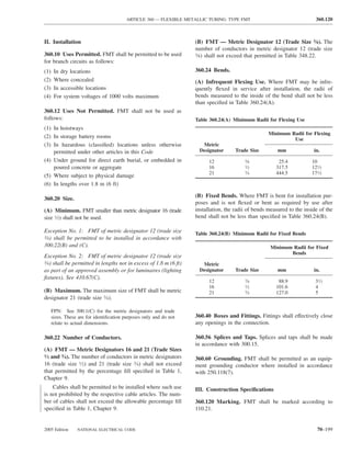
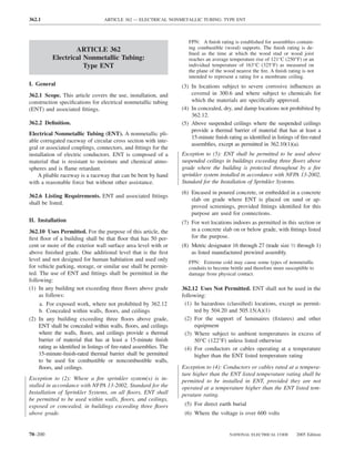
![ARTICLE 362 — ELECTRICAL NONMETALLIC TUBING: TYPE ENT 362.120
(7) In exposed locations, except as permitted by 362.10(1), Exception No. 2: Lengths not exceeding 1.8 m (6 ft) from
362.10(5), and 362.10(7) the last point where the raceway is securely fastened for
(8) In theaters and similar locations, except as provided in connections within an accessible ceiling to luminaire(s)
518.4 and 520.5 [lighting fixture(s)] or other equipment.
(9) Where exposed to the direct rays of the sun, unless
identified as sunlight resistant (B) Supports. Horizontal runs of ENT supported by open-
(10) Where subject to physical damage ings in framing members at intervals not exceeding 900 mm
(3 ft) and securely fastened within 900 mm (3 ft) of termina-
362.20 Size. tion points shall be permitted.
(A) Minimum. ENT smaller than metric designator 16 (trade
size 1⁄2) shall not be used. 362.46 Bushings. Where a tubing enters a box, fitting, or
other enclosure, a bushing or adapter shall be provided to
(B) Maximum. ENT larger than metric designator 53 (trade protect the wire from abrasion unless the box, fitting, or
size 2) shall not be used. enclosure design provides equivalent protection.
FPN: See 300.1(C) for the metric designators and trade
sizes. These are for identification purposes only and do not FPN: See 300.4(F) for the protection of conductors size 4
relate to actual dimensions. AWG or larger.
362.22 Number of Conductors. The number of conduc- 362.48 Joints. All joints between lengths of tubing and
tors shall not exceed that permitted by the percentage fill in
between tubing and couplings, fittings, and boxes shall be
Table 1, Chapter 9.
by an approved method.
Cables shall be permitted to be installed where such use
is not prohibited by the respective cable articles. The num-
ber of cables shall not exceed the allowable percentage fill 362.56 Splices and Taps. Splices and taps shall be made
specified in Table 1, Chapter 9. only in accordance with 300.15.
362.24 Bends — How Made. Bends shall be so made that FPN: See Article 314 for rules on the installation and use
of boxes and conduit bodies.
the tubing will not be damaged and the internal diameter of
the tubing will not be effectively reduced. Bends shall be
permitted to be made manually without auxiliary equip- 362.60 Grounding. Where equipment grounding is required,
ment, and the radius of the curve to the centerline of such a separate equipment grounding conductor shall be installed in
bends shall not be less than shown in Table 2, Chapter 9 the raceway.
using the column “Other Bends.”
362.26 Bends — Number in One Run. There shall not be III. Construction Specifications
more than the equivalent of four quarter bends (360 degrees
362.100 Construction. ENT shall be made of material that
total) between pull points, for example, conduit bodies and
does not exceed the ignitibility, flammability, smoke gen-
boxes.
eration, and toxicity characteristics of rigid (nonplasticized)
362.28 Trimming. All cut ends shall be trimmed inside polyvinyl chloride.
and outside to remove rough edges. ENT, as a prewired manufactured assembly, shall be
provided in continuous lengths capable of being shipped in
362.30 Securing and Supporting. ENT shall be installed a coil, reel, or carton without damage.
as a complete system in accordance with 300.18 and shall
be securely fastened in place and supported in accordance
362.120 Marking. ENT shall be clearly and durably marked
with 362.30(A) and (B).
at least every 3 m (10 ft) as required in the first sentence of
(A) Securely Fastened. ENT shall be securely fastened at 110.21. The type of material shall also be included in the
intervals not exceeding 900 mm (3 ft). In addition, ENT marking. Marking for limited smoke shall be permitted on the
shall be securely fastened in place within 900 mm (3 ft) of tubing that has limited smoke-producing characteristics.
each outlet box, device box, junction box, cabinet, or fitting The type, size, and quantity of conductors used in
where it terminates. prewired manufactured assemblies shall be identified by
Exception No. 1: Lengths not exceeding a distance of 1.8 m means of a printed tag or label attached to each end of the
(6 ft) from a luminaire (fixture) terminal connection for tap manufactured assembly and either the carton, coil, or reel.
connections to lighting luminaires (fixtures) shall be permitted The enclosed conductors shall be marked in accordance
without being secured. with 310.11.
2005 Edition NATIONAL ELECTRICAL CODE 70–201](https://image.slidesharecdn.com/nechandbookversin2005compacta-100921141249-phpapp02/85/Nec-handbook-version-2005-compacta-204-320.jpg)
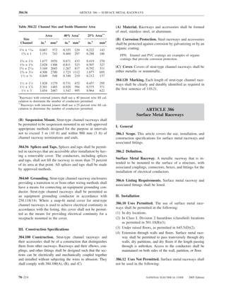
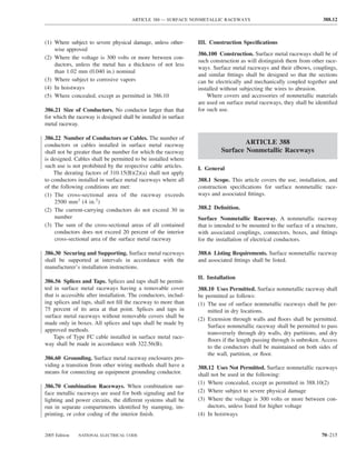
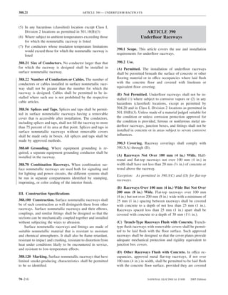
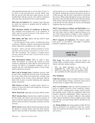
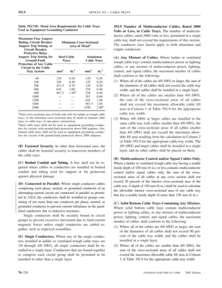
![ARTICLE 392 — CABLE TRAYS 392.9
Table 392.9 Allowable Cable Fill Area for Multiconductor Cables in Ladder, Ventilated Trough, or Solid Bottom Cable Trays
for Cables Rated 2000 Volts or Less
Maximum Allowable Fill Area for Multiconductor Cables
Ladder or Ventilated Trough Cable Trays,
392.9(A) Solid Bottom Cable Trays, 392.9(C)
Column 3
Column 1 Applicable for
Inside Width of Applicable for Column 2a Applicable for 392.9(C)(2) Column 4a Applicable for
Cable Tray 392.9(A)(2) Only 392.9(A)(3) Only Only 392.9(C)(3) Only
mm in. mm2 in.2 mm2 in.2 mm2 in.2 mm2 in.2
150 6.0 4,500 7.0 4,500 – (30 Sd)b 7 – (1.2 Sd)b 3,500 5.5 3,500 – (25 Sdb) 5.5 – Sdb
225 9.0 6,800 10.5 6,800 – (30 Sd) 10.5 – (1.2 Sd) 5,100 8.0 5,100 – (25 Sd) 8.0 – Sd
300 12.0 9,000 14.0 9,000 – (30 Sd) 14 – (1.2 Sd) 7,100 11.0 7,100 – (25 Sd) 11.0 – Sd
450 18.0 13,500 21.0 13,500 – (30 Sd) 21 – (1.2 Sd) 10,600 16.5 10,600 – (25 Sd) 16.5 – Sd
600 24.0 18,000 28.0 18,000 – (30 Sd) 28 – (1.2 Sd) 14,200 22.0 14,200 – (25 Sd) 22.0 – Sd
750 30.0 22,500 35.0 22,500 – (30 Sd) 35 – (1.2 Sd) 17,700 27.5 17,700 – (25 Sd) 27.5 – Sd
900 36.0 27,000 42.0 27,000 – (30 Sd) 42 – (1.2 Sd) 21,300 33.0 21,300 – (25 Sd) 33.0 – Sd
a
The maximum allowable fill areas in Columns 2 and 4 shall be calculated. For example, the maximum
allowable fill in mm2 for a 150-mm wide cable tray in Column 2 shall be 4500 minus (30 multiplied by Sd)
[the maximum allowable fill, in square inches, for a 6-in. wide cable tray in Column 2 shall be 7 minus
(1.2 multiplied by Sd)].
b
The term Sd in Columns 2 and 4 is equal to the sum of the diameters, in mm, of all cables 107.2 mm
(in inches, of all 4/0 AWG) and larger multiconductor cables in the same cable tray with smaller cables.
(3) Where 4/0 AWG or larger cables are installed in the same Table 392.9(E) Allowable Cable Fill Area for Multiconductor
cable tray with cables smaller than 4/0 AWG, the sum of the Cables in Ventilated Channel Cable Trays for Cables Rated
cross-sectional areas of all cables smaller than 4/0 AWG shall 2000 Volts or Less
not exceed the maximum allowable fill area resulting from
the computation in Column 4 of Table 392.9 for the appro- Maximum Allowable Fill Area for
Multiconductor Cables
priate cable tray width. The 4/0 AWG and larger cables shall
be installed in a single layer, and no other cables shall be Column 2
placed on them. Inside Width of Column 1 More Than
Cable Tray One Cable One Cable
(D) Solid Bottom Cable Tray — Multiconductor Con-
trol and/or Signal Cables Only. Where a solid bottom mm in. mm2 in.2 mm2 in.2
cable tray having a usable inside depth of 150 mm (6 in.) or 75 3 1500 2.3 850 1.3
less contains multiconductor control and/or signal cables 100 4 2900 4.5 1600 2.5
only, the sum of the cross-sectional areas of all cables at 150 6 4500 7.0 2450 3.8
any cross section shall not exceed 40 percent of the interior
cross-sectional area of the cable tray. A depth of 150 mm
(6 in.) shall be used to calculate the allowable interior
cross-sectional area of any cable tray that has a usable
inside depth of more than 150 mm (6 in.). (F) Solid Channel Cable Trays. Where solid channel
(E) Ventilated Channel Cable Trays. Where ventilated cable trays contain multiconductor cables of any type, the
channel cable trays contain multiconductor cables of any following shall apply:
type, the following shall apply: (1) Where only one multiconductor cable is installed, the
(1) Where only one multiconductor cable is installed, the cross-sectional area of the cable shall not exceed the
cross-sectional area shall not exceed the value specified value specified in Column 1 of Table 392.9(F).
in Column 1 of Table 392.9(E). (2) Where more than one multiconductor cable is in-
(2) Where more than one multiconductor cable is installed, stalled, the sum of the cross-sectional area of all
the sum of the cross-sectional area of all cables shall not cable shall not exceed the value specified in Col-
exceed the value specified in Column 2 of Table 392.9(E). umn 2 of Table 392.9(F).
2005 Edition NATIONAL ELECTRICAL CODE 70–221](https://image.slidesharecdn.com/nechandbookversin2005compacta-100921141249-phpapp02/85/Nec-handbook-version-2005-compacta-224-320.jpg)
![392.10 ARTICLE 392 — CABLE TRAYS
Table 392.9(F) Allowable Cable Fill Area for Multiconductor (2) Where all of the cables are from 250 kcmil up to
Cables in Solid Channel Cable Trays for Cables Rated 2000 1000 kcmil, the sum of the cross-sectional areas of
Volts or Less
all single-conductor cables shall not exceed the
maximum allowable cable fill area in Column 1 of
Column 2
Inside Width of Column 1 More Than Table 392.10(A) for the appropriate cable tray width.
Cable Tray One Cable One Cable (3) Where 1000 kcmil or larger single-conductor cables
are installed in the same cable tray with single-
mm in. mm2 in.2 mm2 in.2
conductor cables smaller than 1000 kcmil, the sum
50 2 850 1.3 500 0.8 of the cross-sectional areas of all cables smaller than
75 3 1300 2.0 700 1.1 1000 kcmil shall not exceed the maximum allowable
100 4 2400 3.7 1400 2.1
fill area resulting from the computation in Column 2
150 6 3600 5.5 2100 3.2
of Table 392.10(A) for the appropriate cable tray
width.
392.10 Number of Single-Conductor Cables, Rated 2000 (4) Where any of the single conductor cables are 1/0 through
Volts or Less, in Cable Trays. The number of single- 4/0 AWG, the sum of the diameters of all single conductor
conductor cables, rated 2000 volts or less, permitted in a cables shall not exceed the cable tray width.
single cable tray section shall not exceed the requirements of
(B) Ventilated Channel Cable Trays. Where 50 mm (2 in.),
this section. The single conductors, or conductor assemblies,
75 mm (3 in.), 100 mm (4 in.), or 150 mm (6 in.) wide
shall be evenly distributed across the cable tray. The conductor
ventilated channel cable trays contain single-conductor cables,
sizes herein apply to both aluminum and copper conductors.
the sum of the diameters of all single conductors shall not
(A) Ladder or Ventilated Trough Cable Trays. Where exceed the inside width of the channel.
ladder or ventilated trough cable trays contain single-
392.11 Ampacity of Cables, Rated 2000 Volts or Less, in
conductor cables, the maximum number of single conduc-
Cable Trays.
tors shall conform to the following:
(1) Where all of the cables are 1000 kcmil or larger, the (A) Multiconductor Cables. The allowable ampacity of
sum of the diameters of all single conductor cables multiconductor cables, nominally rated 2000 volts or less,
shall not exceed cable tray width, and the cables shall installed according to the requirements of 392.9 shall be as
be installed in a single layer. Conductors that are bound given in Table 310.16 and Table 310.18, subject to the
together to comprise each circuit group shall be permit- provisions of (1), (2), (3), and 310.15(A)(2).
ted to be installed in other than a single layer.
Table 392.10(A) Allowable Cable Fill Area for Single-Conductor Cables in Ladder or Ventilated
Trough Cable Trays for Cables Rated 2000 Volts or Less
Maximum Allowable Fill Area for Single-Conductor Cables in Ladder or Ventilated Trough
Cable Trays
Column 1 Applicable for
Inside Width of Cable Tray 392.10(A)(2) Only Column 2a Applicable for 392.10(A)(3) Only
mm in. mm2 in.2 mm2 in.2
150 6 4,200 6.5 4,200 – (28 Sd)b 6.5 – (1.1 Sd)b
225 9 6,100 9.5 6,100 – (28 Sd) 9.5 – (1.1 Sd)
300 12 8,400 13.0 8,400 – (28 Sd) 13.0 – (1.1 Sd)
450 18 12,600 19.5 12,600 – (28 Sd) 19.5 – (1.1 Sd)
600 24 16,800 26.0 16,800 – (28 Sd) 26.0 – (1.1 Sd)
750 30 21,000 32.5 21,000 – (28 Sd) 32.5 – (1.1 Sd)
900 36 25,200 39.0 25,200 – (28 Sd) 39.0 – (1.1 Sd)
a
The maximum allowable fill areas in Column 2 shall be calculated. For example, the maximum allowable fill, in mm2,
for a 150 mm wide cable tray in Column 2 shall be 4200 minus (28 multiplied by Sd) [the maximum allowable fill, in square
inches, for a 6-in. wide cable tray in Column 2 shall be 6.5 minus (1.1 multiplied by Sd)].
b
The term Sd in Column 2 is equal to the sum of the diameters, in mm, of all cables 507 mm2 (in inches, of all 1000 kcmil)
and larger single-conductor cables in the same ladder or ventilated trough cable tray with small cables.
70–222 NATIONAL ELECTRICAL CODE 2005 Edition](https://image.slidesharecdn.com/nechandbookversin2005compacta-100921141249-phpapp02/85/Nec-handbook-version-2005-compacta-225-320.jpg)
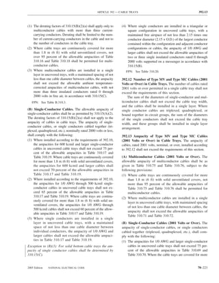
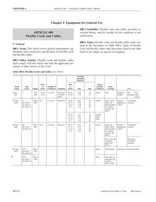
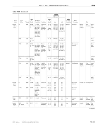
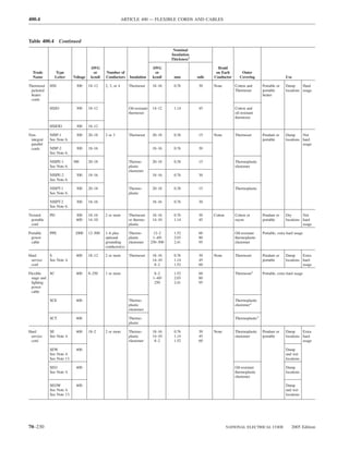
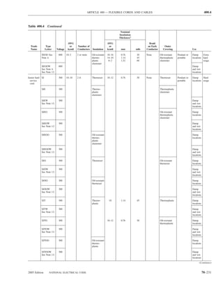
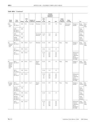
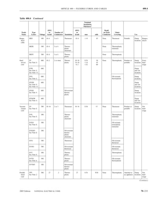
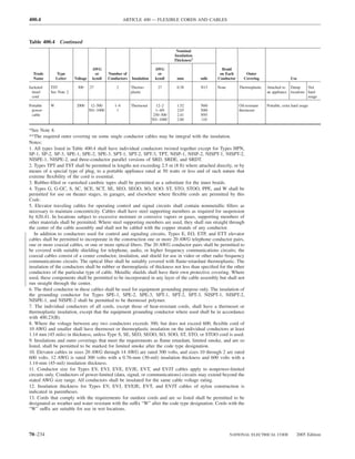
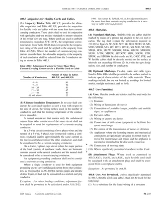
![400.9 ARTICLE 400 — FLEXIBLE CORDS AND CABLES
Table 400.5(A) Allowable Ampacity for Flexible Cords and Cables [Based on Ambient
Temperature of 30°C (86°F). See 400.13 and Table 400.4.]
Thermoset Types C, E, EO, PD, S,
SJ, SJO, SJOW, SJOO, SJOOW,
SO, SOW, SOO, SOOW, SP-1, SP-2,
SP-3, SRD, SV, SVO, SVOO
Thermoplastic Types ET, ETLB,
ETP, ETT, SE, SEW, SEO, SEOW,
SEOOW, SJE, SJEW, SJEO,
SJEOW, SJEOOW, SJT, SJTW,
SJTO, SJTOW, SJTOO, SJTOOW,
SPE-1, SPE-2, SPE-3, SPT-1,
SPT-1W, SPT-2, SPT-2W, SPT-3, ST,
SRDE, SRDT, STO, STOW, STOO, Types HPD,
Thermoplastic STOOW, SVE, SVEO, SVT, SVTO, HPN, HSJ,
Size (AWG) Types TPT, TST SVTOO HSJO, HSJOO
A+ B+
27* 0.5 — — —
20 — 5** *** —
18 — 7 10 10
17 — — 12 13
16 — 10 13 15
15 — — — 17
14 — 15 18 20
12 — 20 25 30
10 — 25 30 35
8 — 35 40 —
6 — 45 55 —
4 — 60 70 —
2 — 80 95 —
*Tinsel cord.
**Elevator cables only.
***7 amperes for elevator cables only; 2 amperes for other types.
+The allowable currents under Column A apply to 3-conductor cords and other multiconductor cords
connected to utilization equipment so that only 3 conductors are current-carrying. The allowable currents
under Column B apply to 2-conductor cords and other multiconductor cords connected to utilization equip-
ment so that only 2 conductors are current carrying.
(2) Where run through holes in walls, structural ceilings, cations permitted by 400.7(A). The repair of hard-service cord
suspended ceilings, dropped ceilings, or floors and junior hard-service cord (see Trade Name column in Table
(3) Where run through doorways, windows, or similar 400.4) 14 AWG and larger shall be permitted if conductors are
openings spliced in accordance with 110.14(B) and the completed splice
(4) Where attached to building surfaces retains the insulation, outer sheath properties, and usage char-
acteristics of the cord being spliced.
Exception to (4): Flexible cord and cable shall be permitted
to be attached to building surfaces in accordance with the
400.10 Pull at Joints and Terminals. Flexible cords and
provisions of 368.56(B)
cables shall be connected to devices and to fittings so that
(5) Where concealed by walls, floors, or ceilings or located tension is not transmitted to joints or terminals.
above suspended or dropped ceilings
(6) Where installed in raceways, except as otherwise per- Exception: Listed portable single-pole devices that are in-
mitted in this Code tended to accommodate such tension at their terminals shall
be permitted to be used with single-conductor flexible cable.
(7) Where subject to physical damage
FPN: Some methods of preventing pull on a cord from being
400.9 Splices. Flexible cord shall be used only in continuous transmitted to joints or terminals are knotting the cord, wind-
lengths without splice or tap where initially installed in appli- ing with tape, and fittings designed for the purpose.
70–236 NATIONAL ELECTRICAL CODE 2005 Edition](https://image.slidesharecdn.com/nechandbookversin2005compacta-100921141249-phpapp02/85/Nec-handbook-version-2005-compacta-239-320.jpg)
![ARTICLE 400 — FLEXIBLE CORDS AND CABLES 400.14
Table 400.5(B) Ampacity of Cable Types SC, SCE, SCT, PPE, G, G-GC, and W. [Based on Ambient Temperature
of 30°C (86°F). See Table 400.4.] Temperature Rating of Cable.
60°C (140°F) 75°C (167°F) 90°C (194°F)
Size (AWG
or kcmil) D1 E2 F3 D1 E2 F3 D1 E2 F3
12 — 31 26 — 37 31 — 42 35
10 — 44 37 — 52 43 — 59 49
8 60 55 48 70 65 57 80 74 65
6 80 72 63 95 88 77 105 99 87
4 105 96 84 125 115 101 140 130 114
3 120 113 99 145 135 118 165 152 133
2 140 128 112 170 152 133 190 174 152
1 165 150 131 195 178 156 220 202 177
1/0 195 173 151 230 207 181 260 234 205
2/0 225 199 174 265 238 208 300 271 237
3/0 260 230 201 310 275 241 350 313 274
4/0 300 265 232 360 317 277 405 361 316
250 340 296 259 405 354 310 455 402 352
300 375 330 289 445 395 346 505 449 393
350 420 363 318 505 435 381 570 495 433
400 455 392 343 545 469 410 615 535 468
500 515 448 392 620 537 470 700 613 536
600 575 — — 690 — — 780 — —
700 630 — — 755 — — 855 — —
750 655 — — 785 — — 885 — —
800 680 — — 815 — — 920 — —
900 730 — — 870 — — 985 — —
1000 780 — — 935 — — 1055 — —
1
The ampacities under subheading D shall be permitted for single-conductor Types SC, SCE, SCT, PPE, and
W cable only where the individual conductors are not installed in raceways and are not in physical contact
with each other except in lengths not to exceed 600 mm (24 in.) where passing through the wall of an
enclosure.
2
The ampacities under subheading E apply to two-conductor cables and other multiconductor cables con-
nected to utilization equipment so that only two conductors are current carrying.
3
The ampacities under subheading F apply to three-conductor cables and other multiconductor cables con-
nected to utilization equipment so that only three conductors are current carrying.
400.11 In Show Windows and Show Cases. Flexible 400.13 Overcurrent Protection. Flexible cords not smaller
cords used in show windows and show cases shall be Type than 18 AWG, and tinsel cords or cords having equivalent
S, SE, SEO, SEOO, SJ, SJE, SJEO, SJEOO, SJO, SJOO, characteristics of smaller size approved for use with specific
SJT, SJTO, SJTOO, SO, SOO, ST, STO, STOO, SEW, appliances, shall be considered as protected against overcur-
SEOW, SEOOW, SJEW, SJEOW, SJEOOW, SJOW, rent by the overcurrent devices described in 240.5.
SJOOW, SJTW, SJTOW, SJTOOW, SOW, SOOW, STW,
STOW, or STOOW. 400.14 Protection from Damage. Flexible cords and cables
Exception No. 1: For the wiring of chain-supported lumi- shall be protected by bushings or fittings where passing
naires (lighting fixtures). through holes in covers, outlet boxes, or similar enclosures.
In industrial establishments where the conditions of
Exception No. 2: As supply cords for portable lamps and maintenance and supervision ensure that only qualified per-
other merchandise being displayed or exhibited. sons service the installation, flexible cords and cables shall
be permitted to be installed in aboveground raceways that
400.12 Minimum Size. The individual conductors of a
are no longer than 15 m (50 ft) to protect the flexible cord
flexible cord or cable shall not be smaller than the sizes in
or cable from physical damage. Where more than three
Table 400.4.
current-carrying conductors are installed within the race-
Exception: The size of the insulated ground-check conduc- way, the allowable ampacity shall be reduced in accordance
tor of Type G-GC cables shall be not smaller than 10 AWG. with Table 400.5.
2005 Edition NATIONAL ELECTRICAL CODE 70–237](https://image.slidesharecdn.com/nechandbookversin2005compacta-100921141249-phpapp02/85/Nec-handbook-version-2005-compacta-240-320.jpg)
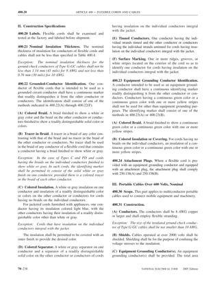
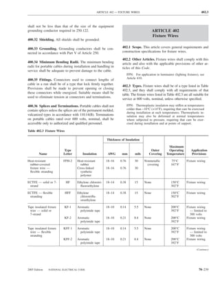
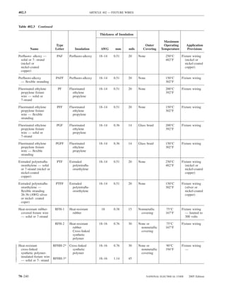
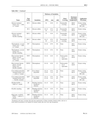
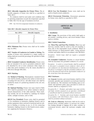
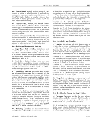
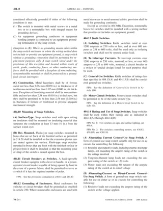
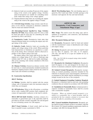
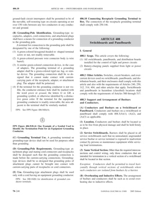
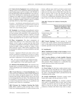
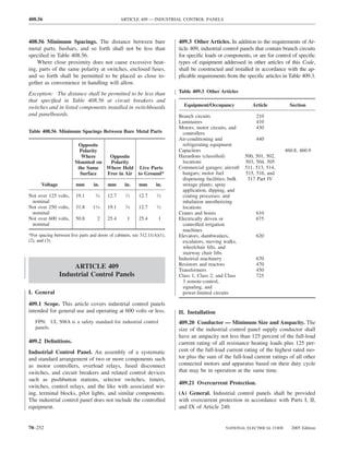
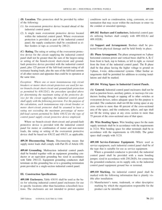
![410.1 ARTICLE 410 — LUMINAIRES (LIGHTING FIXTURES), LAMPHOLDERS, AND LAMPS
(2) Supply voltage, phase, frequency, and full-load current. II. Luminaire (Fixture) Locations
(3) Short-circuit current rating of the industrial control
panel based on one of the following: 410.4 Luminaires (Fixtures) in Specific Locations.
a. Short-circuit current rating of a listed and labeled (A) Wet and Damp Locations. Luminaires (fixtures) in-
assembly stalled in wet or damp locations shall be installed so that
b. Short-circuit current rating established utilizing an water cannot enter or accumulate in wiring compartments,
approved method lampholders, or other electrical parts. All luminaires (fix-
FPN: UL 508A-2001, Supplement SB, is an example of an
tures) installed in wet locations shall be marked, “Suitable
approved method. for Wet Locations.” All luminaires (fixtures) installed in damp
locations shall be marked, “Suitable for Wet Locations” or
(4) If the industrial control panel is intended as service “Suitable for Damp Locations.”
equipment, it shall be marked to identify it as being
suitable for use as service equipment. (B) Corrosive Locations. Luminaires (fixtures) installed
(5) Electrical wiring diagram or the number of the index to in corrosive locations shall be of a type suitable for such
the electrical drawings showing the electrical wiring locations.
diagram.
(6) An enclosure type number shall be marked on the in- (C) In Ducts or Hoods. Luminaires (fixtures) shall be per-
dustrial control panel enclosure. mitted to be installed in commercial cooking hoods where
all of the following conditions are met:
(1) The luminaire (fixture) shall be identified for use within
commercial cooking hoods and installed such that the
temperature limits of the materials used are not exceeded.
ARTICLE 410 (2) The luminaire (fixture) shall be constructed so that all
Luminaires (Lighting Fixtures), exhaust vapors, grease, oil, or cooking vapors are ex-
Lampholders, and Lamps cluded from the lamp and wiring compartment. Diffus-
ers shall be resistant to thermal shock.
I. General (3) Parts of the luminaire (fixture) exposed within the hood
shall be corrosion resistant or protected against corro-
410.1 Scope. This article covers luminaires (lighting fix- sion, and the surface shall be smooth so as not to col-
tures), lampholders, pendants, incandescent filament lamps, lect deposits and to facilitate cleaning.
arc lamps, electric-discharge lamps, decorative lighting (4) Wiring methods and materials supplying the lumi-
products, lighting accessories for temporary seasonal and naire(s) [fixture(s)] shall not be exposed within the
holiday use, portable flexible lighting products, and the wir- cooking hood.
ing and equipment forming part of such products and light-
ing installations. FPN: See 110.11 for conductors and equipment exposed to
deteriorating agents.
410.2 Application of Other Articles. Equipment for use in
hazardous (classified) locations shall conform to Articles 500 (D) Bathtub and Shower Areas. No parts of cord-
through 517. Lighting systems operating at 30 volts or less connected luminaires (fixtures), chain-, cable-, or cord-
shall conform to Article 411. Arc lamps used in theaters shall suspended-luminaires (fixtures), lighting track, pendants, or
comply with 520.61, and arc lamps used in projection ma- ceiling-suspended (paddle) fans shall be located within a
chines shall comply with 540.20. Arc lamps used on constant- zone measured 900 mm (3 ft) horizontally and 2.5 m (8 ft)
current systems shall comply with the general requirements of vertically from the top of the bathtub rim or shower stall
Article 490. threshold. This zone is all encompassing and includes the
zone directly over the tub or shower stall. Luminaires
410.3 Live Parts. Luminaires (fixtures), lampholders, and (lighting fixtures) located in this zone shall be listed for
lamps shall have no live parts normally exposed to contact. damp locations, or listed for wet locations where subject to
Exposed accessible terminals in lampholders and switches shower spray.
shall not be installed in metal luminaire (fixture) canopies
(E) Luminaires (Fixtures) in Indoor Sports, Mixed-Use,
or in open bases of portable table or floor lamps.
and All-Purpose Facilities. Luminaires (fixtures) subject
Exception: Cleat-type lampholders located at least 2.5 m to physical damage, using a mercury vapor or metal halide
(8 ft) above the floor shall be permitted to have exposed lamp, installed in playing and spectator seating areas of
terminals. indoor sports, mixed-use, or all-purpose facilities shall be
70–254 NATIONAL ELECTRICAL CODE 2005 Edition](https://image.slidesharecdn.com/nechandbookversin2005compacta-100921141249-phpapp02/85/Nec-handbook-version-2005-compacta-257-320.jpg)
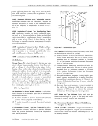
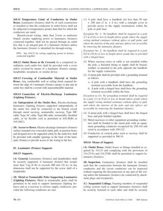
![ARTICLE 410 — LUMINAIRES (LIGHTING FIXTURES), LAMPHOLDERS, AND LAMPS 410.27
attached to the building structure at appropriate intervals. Exception No. 2: Where no equipment grounding conduc-
Luminaires (fixtures) shall be securely fastened to the ceil- tor exists at the outlet, replacement luminaires (fixtures)
ing framing member by mechanical means such as bolts, that are GFCI protected shall not be required to be con-
screws, or rivets. Listed clips identified for use with the nected to an equipment grounding conductor.
type of ceiling framing member(s) and luminaire(s) [fix-
ture(s)] shall also be permitted. 410.20 Equipment Grounding Conductor Attachment.
Luminaires (fixtures) with exposed metal parts shall be pro-
(D) Luminaire (Fixture) Studs. Luminaire (fixture) studs vided with a means for connecting an equipment grounding
that are not a part of outlet boxes, hickeys, tripods, and conductor for such luminaires (fixtures).
crowfeet shall be made of steel, malleable iron, or other
410.21 Methods of Grounding. Luminaires (fixtures) and
material suitable for the application.
equipment shall be considered grounded where mechani-
(E) Insulating Joints. Insulating joints that are not designed cally connected to an equipment grounding conductor as
to be mounted with screws or bolts shall have an exterior specified in 250.118 and sized in accordance with 250.122.
metal casing, insulated from both screw connections.
VI. Wiring of Luminaires (Fixtures)
(F) Raceway Fittings. Raceway fittings used to support a
luminaire(s) [lighting fixture(s)] shall be capable of supporting 410.22 Luminaire (Fixture) Wiring — General. Wiring
the weight of the complete fixture assembly and lamp(s). on or within fixtures shall be neatly arranged and shall not be
exposed to physical damage. Excess wiring shall be avoided.
(G) Busways. Luminaires (fixtures) shall be permitted to Conductors shall be arranged so that they are not subjected to
be connected to busways in accordance with 368.17(C). temperatures above those for which they are rated.
(H) Trees. Outdoor luminaires (lighting fixtures) and associ- 410.23 Polarization of Luminaires (Fixtures). Luminaires
ated equipment shall be permitted to be supported by trees. (fixtures) shall be wired so that the screw shells of lamphold-
ers are connected to the same luminaire (fixture) or circuit
FPN No. 1: See 225.26 for restrictions for support of conductor or terminal. The grounded conductor, where con-
overhead conductors.
nected to a screw-shell lampholder, shall be connected to the
FPN No. 2: See 300.5(D) for protection of conductors. screw shell.
410.24 Conductor Insulation. Luminaires (fixtures) shall
V. Grounding
be wired with conductors having insulation suitable for the
410.17 General. Luminaires (fixtures) and lighting equip- environmental conditions, current, voltage, and temperature
ment shall be grounded as required in Article 250 and Part V to which the conductors will be subjected.
of this article. FPN: For ampacity of luminaire (fixture) wire, maximum
operating temperature, voltage limitations, minimum wire
410.18 Exposed Luminaire (Fixture) Parts. size, and so forth, see Article 402.
(A) Exposed Conductive Parts. Exposed metal parts shall 410.27 Pendant Conductors for Incandescent
be grounded or insulated from ground and other conducting Filament Lamps.
surfaces or be inaccessible to unqualified personnel. Lamp
(A) Support. Pendant lampholders with permanently at-
tie wires, mounting screws, clips, and decorative bands on
tached leads, where used for other than festoon wiring,
glass spaced at least 38 mm (11⁄2 in.) from lamp terminals shall be hung from separate stranded rubber-covered con-
shall not be required to be grounded. ductors that are soldered directly to the circuit conductors
but supported independently thereof.
(B) Made of Insulating Material. Luminaires (fixtures)
directly wired or attached to outlets supplied by a wiring (B) Size. Unless part of listed decorative lighting assem-
method that does not provide a ready means for grounding blies, pendant conductors shall not be smaller than 14 AWG
shall be made of insulating material and shall have no ex- for mogul-base or medium-base screw-shell lampholders or
posed conductive parts. smaller than 18 AWG for intermediate or candelabra-base
lampholders.
Exception No. 1: Replacement luminaires (fixtures) shall be
permitted to connect an equipment grounding conductor from (C) Twisted or Cabled. Pendant conductors longer than
the outlet in compliance with 250.130(C). The luminaire (fix- 900 mm (3 ft) shall be twisted together where not cabled in
ture) shall then be grounded in accordance with 410.18(A). a listed assembly.
2005 Edition NATIONAL ELECTRICAL CODE 70–257](https://image.slidesharecdn.com/nechandbookversin2005compacta-100921141249-phpapp02/85/Nec-handbook-version-2005-compacta-260-320.jpg)
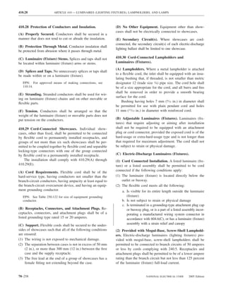
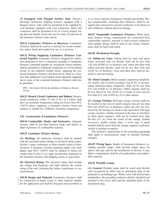
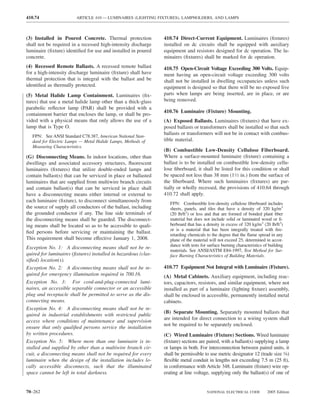
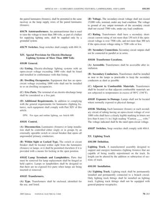
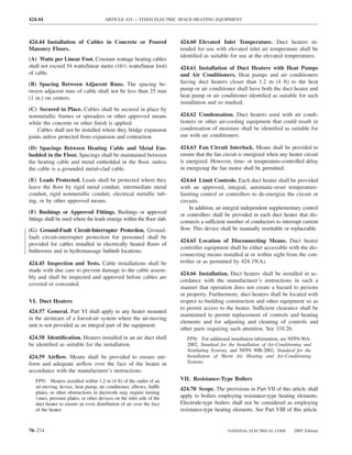
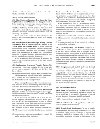
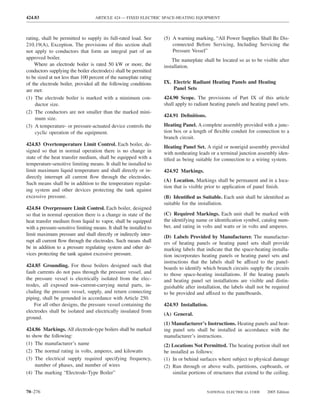
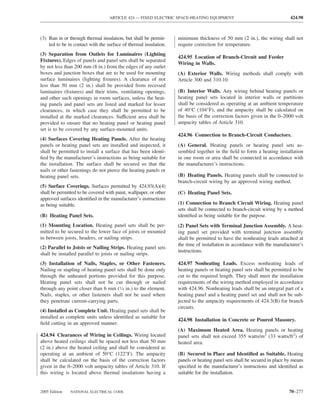
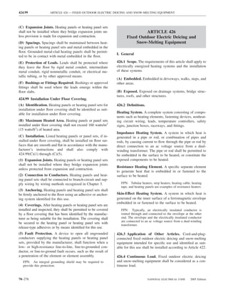
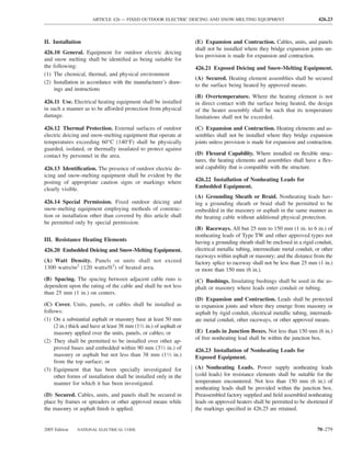
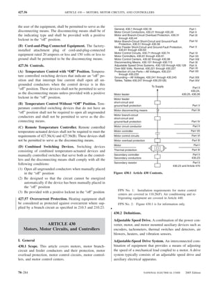

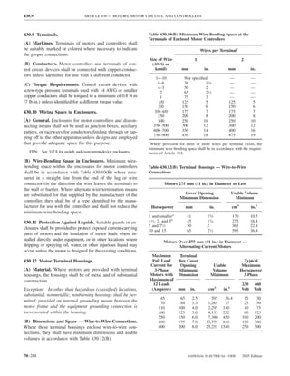
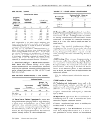
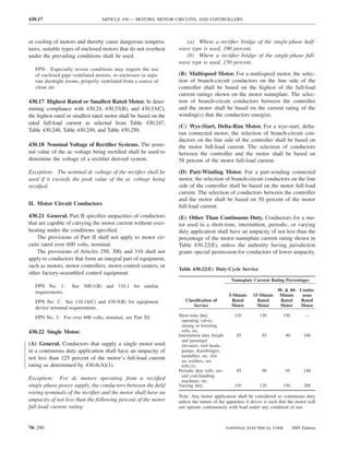
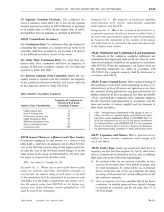
![430.29 ARTICLE 430 — MOTORS, MOTOR CIRCUITS, AND CONTROLLERS
(3) Have an ampacity not less than the feeder conductors III. Motor and Branch-Circuit Overload Protection
Exception: Feeder taps over 7.5 m (25 ft) long. In high-bay 430.31 General. Part III specifies overload devices intended
manufacturing buildings [over 11 m (35 ft) high at walls], to protect motors, motor-control apparatus, and motor branch-
where conditions of maintenance and supervision ensure that circuit conductors against excessive heating due to motor
only qualified persons service the systems, conductors tapped overloads and failure to start.
to a feeder shall be permitted to be not over 7.5 m (25 ft) long Overload in electrical apparatus is an operating overcur-
horizontally and not over 30.0 m (100 ft) in total length where rent that, when it persists for a sufficient length of time,
all of the following conditions are met: would cause damage or dangerous overheating of the appa-
ratus. It does not include short circuits or ground faults.
(a) The ampacity of the tap conductors is not less than These provisions shall not be interpreted as requiring
one-third that of the feeder conductors. overload protection where it might introduce additional or
(b) The tap conductors terminate with a single circuit increased hazards, as in the case of fire pumps.
breaker or a single set of fuses conforming with (1) Part IV,
where the load-side conductors are a branch circuit, or (2) FPN: For protection of fire pump supply conductors, see
Part V, where the load-side conductors are a feeder. 695.6.
(c) The tap conductors are suitably protected from The provisions of Part III shall not apply to motor cir-
physical damage and are installed in raceways. cuits rated over 600 volts, nominal.
(d) The tap conductors are continuous from end-to-
end and contain no splices. FPN No. 1: For over 600 volts, nominal, see Part XI.
(e) The tap conductors shall be 6 AWG copper or 4 AWG FPN No. 2: See Annex D, Example No. D8.
aluminum or larger.
(f) The tap conductors shall not penetrate walls, 430.32 Continuous-Duty Motors.
floors, or ceilings.
(g) The tap shall not be made less than 9.0 m (30 ft) (A) More Than 1 Horsepower. Each motor used in a
from the floor. continuous duty application and rated more than 1 hp
shall be protected against overload by one of the means
430.29 Constant Voltage Direct-Current Motors — in 430.32(A)(1) through (A)(4).
Power Resistors. Conductors connecting the motor control- (1) Separate Overload Device. A separate overload de-
ler to separately mounted power accelerating and dynamic vice that is responsive to motor current. This device shall
braking resistors in the armature circuit shall have an ampacity be selected to trip or shall be rated at no more than the
not less than the value calculated from Table 430.29 using following percent of the motor nameplate full-load current
motor full-load current. If an armature shunt resistor is used, rating:
the power accelerating resistor conductor ampacity shall be
calculated using the total of motor full-load current and arma-
Motors with a marked service 125%
ture shunt resistor current. factor 1.15 or greater
Armature shunt resistor conductors shall have an am- Motors with a marked 125%
pacity of not less than that calculated from Table 430.29 temperature rise 40°C
using rated shunt resistor current as full-load current. or less
All other motors 115%
Table 430.29 Conductor Rating Factors for Power Resistors Modification of this value shall be permitted as provided in
430.32(C). For a multispeed motor, each winding connec-
Ampacity of tion shall be considered separately.
Time in Seconds
Conductor in Where a separate motor overload device is connected so
Percent of
On Off Full-Load Current that it does not carry the total current designated on the
motor nameplate, such as for wye-delta starting, the proper
5 75 35 percentage of nameplate current applying to the selection or
10 70 45 setting of the overload device shall be clearly designated on
15 75 55
the equipment, or the manufacturer’s selection table shall
15 45 65
15 30 75 take this into account.
15 15 85
Continuous Duty 110 FPN: Where power factor correction capacitors are installed
on the load side of the motor overload device, see 460.9.
70–292 NATIONAL ELECTRICAL CODE 2005 Edition](https://image.slidesharecdn.com/nechandbookversin2005compacta-100921141249-phpapp02/85/Nec-handbook-version-2005-compacta-295-320.jpg)
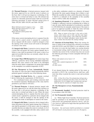
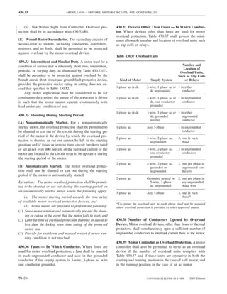
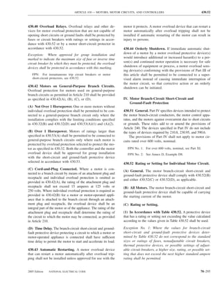
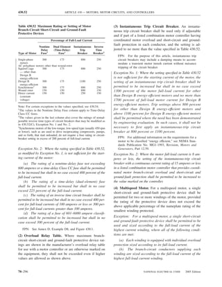
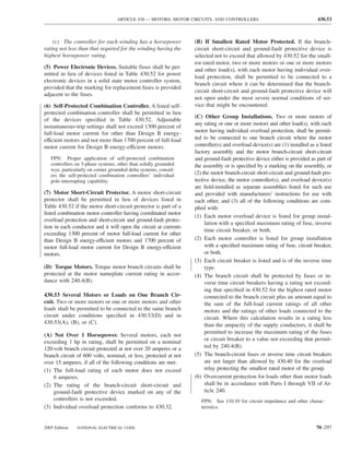
![430.54 ARTICLE 430 — MOTORS, MOTOR CIRCUITS, AND CONTROLLERS
(D) Single Motor Taps. For group installations described V. Motor Feeder Short-Circuit and Ground-Fault
above, the conductors of any tap supplying a single motor Protection
shall not be required to have an individual branch-circuit
430.61 General. Part V specifies protective devices intended
short-circuit and ground-fault protective device, provided
to protect feeder conductors supplying motors against overcur-
they comply with one of the following:
rents due to short circuits or grounds.
(1) No conductor to the motor shall have an ampacity less
than that of the branch-circuit conductors. FPN: See Annex D, Example D8.
(2) No conductor to the motor shall have an ampacity less
430.62 Rating or Setting — Motor Load.
than one-third that of the branch-circuit conductors, with a
minimum in accordance with 430.22, the conductors to (A) Specific Load. A feeder supplying a specific fixed mo-
the motor overload device being not more than 7.5 m tor load(s) and consisting of conductor sizes based on
(25 ft) long and being protected from physical damage. 430.24 shall be provided with a protective device having a
(3) Conductors from the branch-circuit short-circuit and rating or setting not greater than the largest rating or setting
ground-fault protective device to a listed manual motor of the branch-circuit short-circuit and ground-fault protec-
controller additionally marked “Suitable for Tap Con- tive device for any motor supplied by the feeder [based on
ductor Protection in Group Installations” shall be per- the maximum permitted value for the specific type of a
mitted to have an ampacity not less than 1⁄10 the rating or protective device in accordance with 430.52, or 440.22(A)
setting of the branch-circuit short-circuit and ground-fault for hermetic refrigerant motor-compressors], plus the sum
protective device. The conductors from the controller to of the full-load currents of the other motors of the group.
the motor shall have an ampacity in accordance with Where the same rating or setting of the branch-circuit
430.22. The conductors from the branch-circuit short- short-circuit and ground-fault protective device is used on
circuit and ground-fault protective device to the controller two or more of the branch circuits supplied by the feeder,
shall (1) be suitably protected from physical damage and one of the protective devices shall be considered the largest
enclosed either by an enclosed controller or by a raceway for the above calculations.
and shall be not more than 3 m (10 ft) long or (2) shall
Exception No. 1: Where one or more instantaneous trip
have an ampacity not less than that of the branch circuit
circuit breakers or motor short-circuit protectors are used for
conductors.
motor branch-circuit short-circuit and ground-fault protection
430.54 Multimotor and Combination-Load Equipment. as permitted in 430.52(C), the procedure provided above for
The rating of the branch-circuit short-circuit and ground- determining the maximum rating of the feeder protective de-
fault protective device for multimotor and combination- vice shall apply with the following provision: For the purpose
load equipment shall not exceed the rating marked on the of the calculation, each instantaneous trip circuit breaker or
equipment in accordance with 430.7(D). motor short-circuit protector shall be assumed to have a rat-
ing not exceeding the maximum percentage of motor full-load
430.55 Combined Overcurrent Protection. Motor branch- current permitted by Table 430.52 for the type of feeder pro-
circuit short-circuit and ground-fault protection and motor tective device employed.
overload protection shall be permitted to be combined in a
single protective device where the rating or setting of the Exception No. 2: Where the feeder overcurrent protective
device provides the overload protection specified in 430.32. device also provides overcurrent protection for a motor
control center, the provisions of 430.94 shall apply.
430.56 Branch-Circuit Protective Devices — In Which
FPN: See Annex D, Example D8.
Conductor. Branch-circuit protective devices shall comply
with the provisions of 240.20. (B) Other Installations. Where feeder conductors have an
430.57 Size of Fuseholder. Where fuses are used for mo- ampacity greater than required by 430.24, the rating or setting
tor branch-circuit short-circuit and ground-fault protection, of the feeder overcurrent protective device shall be permitted
the fuseholders shall not be of a smaller size than required to be based on the ampacity of the feeder conductors.
to accommodate the fuses specified by Table 430.52.
430.63 Rating or Setting — Power and Lighting Loads.
Exception: Where fuses having time delay appropriate for Where a feeder supplies a motor load and, in addition, a
the starting characteristics of the motor are used, it shall be lighting or a lighting and appliance load, the feeder protec-
permitted to use fuseholders sized to fit the fuses that are used. tive device shall have a rating sufficient to carry the lighting
430.58 Rating of Circuit Breaker. A circuit breaker for or lighting and appliance load, plus the following:
motor branch-circuit short-circuit and ground-fault protec- (1) For a single motor, the rating permitted by 430.52
tion shall have a current rating in accordance with 430.52 (2) For a single hermetic refrigerant motor-compressor, the
and 430.110. rating permitted by 440.22
70–298 NATIONAL ELECTRICAL CODE 2005 Edition](https://image.slidesharecdn.com/nechandbookversin2005compacta-100921141249-phpapp02/85/Nec-handbook-version-2005-compacta-301-320.jpg)
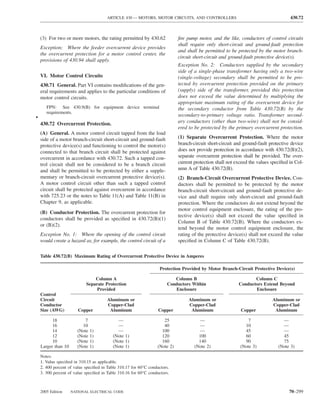
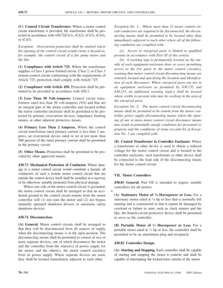
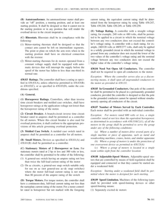
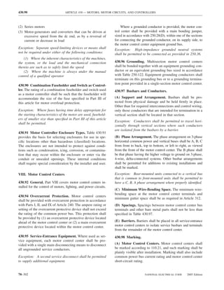
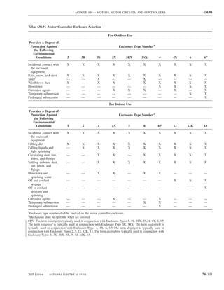
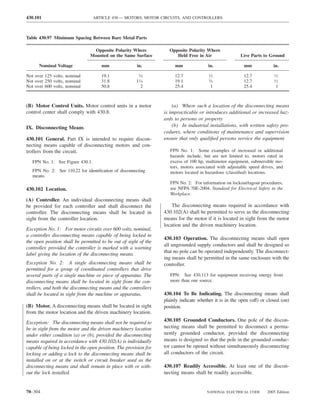
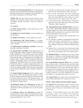
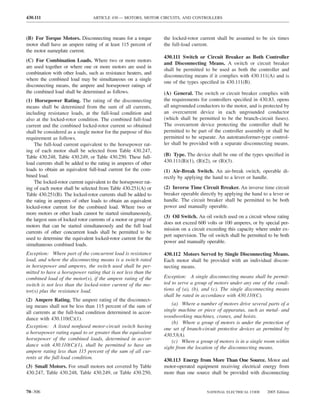
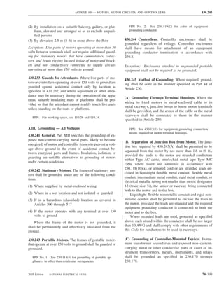
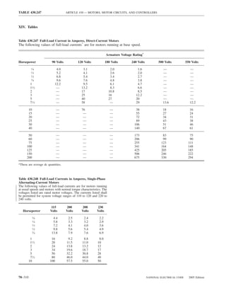
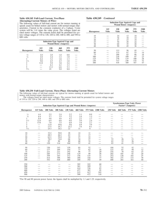
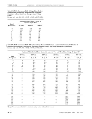

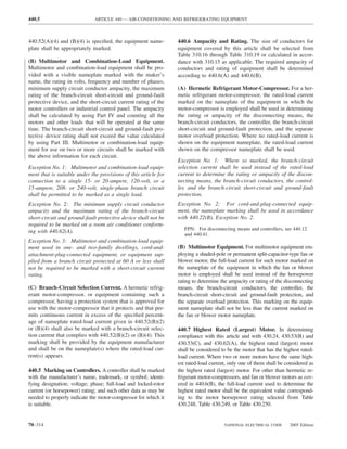
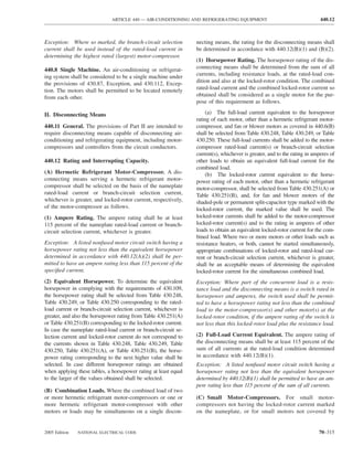
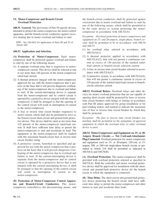
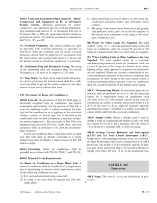
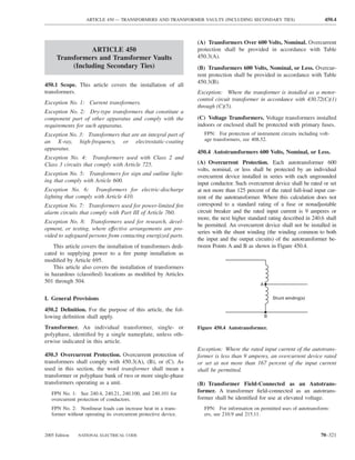
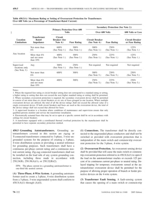
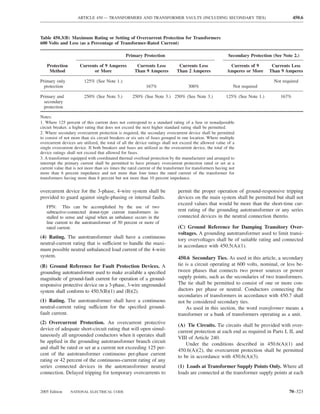
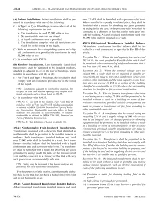
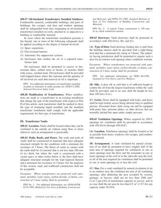
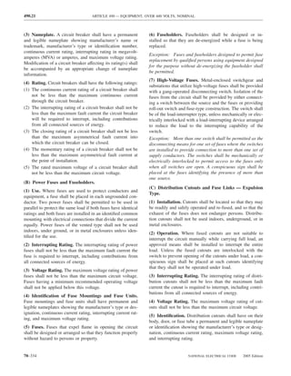
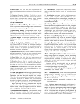
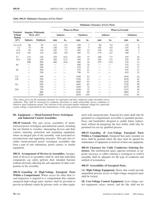
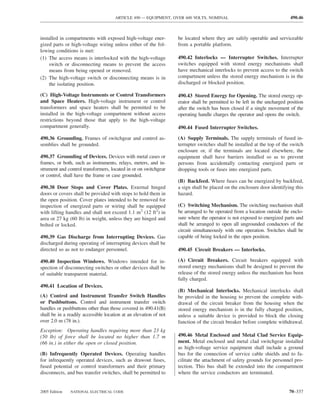
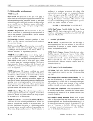
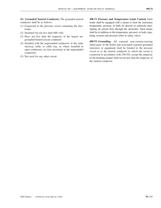
![ARTICLE 500 — HAZARDOUS (CLASSIFIED) LOCATIONS, CLASSES I, II, AND III, DIVISIONS 1 AND 2 500.5
FPN No. 2: In some Division 1 locations, ignitible con- flammable liquids or liquefied or compressed gases in
centrations of flammable gases or vapors may be present sealed containers may be considered either hazardous (clas-
continuously or for long periods of time. Examples include sified) or unclassified locations. See NFPA 30-2003, Flam-
the following: mable and Combustible Liquids Code, and NFPA 58-2004,
Liquefied Petroleum Gas Code.
(1) The inside of inadequately vented enclosures contain-
ing instruments normally venting flammable gases or
vapors to the interior of the enclosure (C) Class II Locations. Class II locations are those that are
(2) The inside of vented tanks containing volatile flam- hazardous because of the presence of combustible dust. Class
mable liquids II locations shall include those specified in 500.5(C)(1) and
(3) The area between the inner and outer roof sections of a (C)(2).
floating roof tank containing volatile flammable fluids
(4) Inadequately ventilated areas within spraying or coat- (1) Class II, Division 1. A Class II, Division 1 location is
ing operations using volatile flammable fluids a location
(5) The interior of an exhaust duct that is used to vent
ignitible concentrations of gases or vapors (1) In which combustible dust is in the air under normal
operating conditions in quantities sufficient to produce
Experience has demonstrated the prudence of avoiding
the installation of instrumentation or other electric equip- explosive or ignitible mixtures, or
ment in these particular areas altogether or where it cannot (2) Where mechanical failure or abnormal operation of
be avoided because it is essential to the process and other machinery or equipment might cause such explosive or
locations are not feasible [see 500.5(A), FPN] using elec-
ignitible mixtures to be produced, and might also pro-
tric equipment or instrumentation approved for the specific
application or consisting of intrinsically safe systems as vide a source of ignition through simultaneous failure
described in Article 504. of electric equipment, through operation of protection
devices, or from other causes, or
(2) Class I, Division 2. A Class I, Division 2 location is a
location (3) In which Group E combustible dusts may be present in
quantities sufficient to be hazardous.
(1) In which volatile flammable liquids or flammable gases
are handled, processed, or used, but in which the liq- FPN: Dusts containing magnesium or aluminum are par-
uids, vapors, or gases will normally be confined within ticularly hazardous, and the use of extreme precaution is
closed containers or closed systems from which they necessary to avoid ignition and explosion.
can escape only in case of accidental rupture or break- (2) Class II, Division 2. A Class II, Division 2 location is
down of such containers or systems or in case of ab- a location
normal operation of equipment, or
(1) In which combustible dust due to abnormal operations
(2) In which ignitible concentrations of gases or vapors are may be present in the air in quantities sufficient to
normally prevented by positive mechanical ventilation produce explosive or ignitible mixtures; or
and which might become hazardous through failure or
(2) Where combustible dust accumulations are present but
abnormal operation of the ventilating equipment, or
are normally insufficient to interfere with the normal
(3) That is adjacent to a Class I, Division 1 location, and to operation of electrical equipment or other apparatus,
which ignitible concentrations of gases or vapors might but could as a result of infrequent malfunctioning of
occasionally be communicated unless such communi- handling or processing equipment become suspended
cation is prevented by adequate positive-pressure ven- in the air; or
tilation from a source of clean air and effective safe-
(3) In which combustible dust accumulations on, in, or in
guards against ventilation failure are provided.
the vicinity of the electrical equipment could be suffi-
FPN No. 1: This classification usually includes locations cient to interfere with the safe dissipation of heat from
where volatile flammable liquids or flammable gases or electrical equipment, or could be ignitible by abnormal
vapors are used but that, in the judgment of the authority operation or failure of electrical equipment.
having jurisdiction, would become hazardous only in case
of an accident or of some unusual operating condition. The FPN No. 1: The quantity of combustible dust that may be
quantity of flammable material that might escape in case of present and the adequacy of dust removal systems are fac-
accident, the adequacy of ventilating equipment, the total tors that merit consideration in determining the classifica-
area involved, and the record of the industry or business tion and may result in an unclassified area.
with respect to explosions or fires are all factors that merit
consideration in determining the classification and extent of FPN No. 2: Where products such as seed are handled in a
each location. manner that produces low quantities of dust, the amount of
dust deposited may not warrant classification.
FPN No. 2: Piping without valves, checks, meters, and
similar devices would not ordinarily introduce a hazardous
condition even though used for flammable liquids or gases. (D) Class III Locations. Class III locations are those that
Depending on factors such as the quantity and size of the are hazardous because of the presence of easily ignitible
containers and ventilation, locations used for the storage of fibers or flyings, but in which such fibers or flyings are not
2005 Edition NATIONAL ELECTRICAL CODE 70–343](https://image.slidesharecdn.com/nechandbookversin2005compacta-100921141249-phpapp02/85/Nec-handbook-version-2005-compacta-346-320.jpg)
![500.6 ARTICLE 500 — HAZARDOUS (CLASSIFIED) LOCATIONS, CLASSES I, II, AND III, DIVISIONS 1 AND 2
likely to be in suspension in the air in quantities sufficient experimental safe gap (MESG) value less than or equal to
to produce ignitible mixtures. Class III locations shall in- 0.45 mm or a minimum igniting current ratio (MIC ratio)
clude those specified in 500.5(D)(1) and (D)(2). less than or equal to 0.40. [NFPA 497:3.3]
(1) Class III, Division 1. A Class III, Division 1 location FPN: A typical Class I, Group B material is hydrogen.
is a location in which easily ignitible fibers or materials Exception No. 1: Group D equipment shall be permitted to
producing combustible flyings are handled, manufactured, be used for atmospheres containing butadiene, provided all
or used. conduit runs into explosionproof equipment are provided
FPN No. 1: Such locations usually include some parts of with explosionproof seals installed within 450 mm (18 in.)
rayon, cotton, and other textile mills; combustible fiber manu- of the enclosure.
facturing and processing plants; cotton gins and cotton-seed
mills; flax-processing plants; clothing manufacturing plants; Exception No. 2: Group C equipment shall be permitted to
woodworking plants; and establishments and industries in- be used for atmospheres containing allyl glycidyl ether,
volving similar hazardous processes or conditions. n-butyl glycidyl ether, ethylene oxide, propylene oxide, and
FPN No. 2: Easily ignitible fibers and flyings include acrolein, provided all conduit runs into explosionproof
rayon, cotton (including cotton linters and cotton waste), equipment are provided with explosionproof seals installed
sisal or henequen, istle, jute, hemp, tow, cocoa fiber, oa- within 450 mm (18 in.) of the enclosure.
kum, baled waste kapok, Spanish moss, excelsior, and other
materials of similar nature. (3) Group C. Flammable gas, flammable liquid–produced
vapor, or combustible liquid–produced vapor mixed with
(2) Class III, Division 2. A Class III, Division 2 location
air that may burn or explode, having either a maximum
is a location in which easily ignitible fibers are stored or
experimental safe gap (MESG) value greater than 0.45 mm
handled other than in the process of manufacture.
and less than or equal to 0.75 mm, or a minimum igniting
current ratio (MIC ratio) greater than 0.40 and less than or
500.6 Material Groups. For purposes of testing, approval,
equal to 0.80. [NFPA 497:3.3]
and area classification, various air mixtures (not oxygen-
enriched) shall be grouped in accordance with 500.6(A) FPN: A typical Class I, Group C material is ethylene.
and 500.6(B).
(4) Group D. Flammable gas, flammable liquid–produced
Exception: Equipment identified for a specific gas, vapor, vapor, or combustible liquid–produced vapor mixed with
or dust. air that may burn or explode, having either a maximum
FPN: This grouping is based on the characteristics of the experimental safe gap (MESG) value greater than 0.75 mm
materials. Facilities are available for testing and identifying or a minimum igniting current ratio (MIC ratio) greater
equipment for use in the various atmospheric groups. than 0.80. [NFPA 497:3.3]
FPN No. 1: A typical Class I, Group D material is
(A) Class I Group Classifications. Class I groups shall be propane.
according to 500.6(A)(1) through (A)(4).
FPN No. 2: For classification of areas involving ammonia
FPN No. 1: FPN Nos. 2 and 3 apply to 500.6(A). atmospheres, see ANSI/ASHRAE 15-1994, Safety Code for
FPN No. 2: The explosion characteristics of air mixtures Mechanical Refrigeration, and ANSI/CGA G2.1-1989, Safety
of gases or vapors vary with the specific material involved. Requirements for the Storage and Handling of Anhydrous
For Class I locations, Groups A, B, C, and D, the classifi- Ammonia.
cation involves determinations of maximum explosion
pressure and maximum safe clearance between parts of a (B) Class II Group Classifications. Class II groups shall
clamped joint in an enclosure. It is necessary, therefore, that be in accordance with 500.6(B)(1) through (B)(3).
equipment be identified not only for class but also for the
specific group of the gas or vapor that will be present. (1) Group E. Atmospheres containing combustible metal
FPN No. 3: Certain chemical atmospheres may have char- dusts, including aluminum, magnesium, and their commer-
acteristics that require safeguards beyond those required for cial alloys, or other combustible dusts whose particle size,
any of the Class I groups. Carbon disulfide is one of these abrasiveness, and conductivity present similar hazards in
chemicals because of its low ignition temperature [100°C the use of electrical equipment. [NFPA 499:3.3]
(212°F)] and the small joint clearance permitted to arrest its
flame. FPN: Certain metal dusts may have characteristics that re-
quire safeguards beyond those required for atmospheres con-
(1) Group A. Acetylene. [NFPA 497:3.3] taining the dusts of aluminum, magnesium, and their commer-
cial alloys. For example, zirconium, thorium, and uranium
(2) Group B. Flammable gas, flammable liquid–produced dusts have extremely low ignition temperatures [as low as
vapor, or combustible liquid–produced vapor mixed with 20°C (68°F)] and minimum ignition energies lower than any
air that may burn or explode, having either a maximum material classified in any of the Class I or Class II groups.
70–344 NATIONAL ELECTRICAL CODE 2005 Edition](https://image.slidesharecdn.com/nechandbookversin2005compacta-100921141249-phpapp02/85/Nec-handbook-version-2005-compacta-347-320.jpg)
![ARTICLE 500 — HAZARDOUS (CLASSIFIED) LOCATIONS, CLASSES I, II, AND III, DIVISIONS 1 AND 2 500.7
(2) Group F. Atmospheres containing combustible carbon- installation of intrinsically safe apparatus and wiring shall
aceous dusts that have more than 8 percent total entrapped be in accordance with the requirements of Article 504.
volatiles (see ASTM D 3175-89, Standard Test Method for
Volatile Material in the Analysis Sample for Coal and (F) Nonincendive Circuit. This protection technique shall
Coke, for coal and coke dusts) or that have been sensitized be permitted for equipment in Class I, Division 2; Class II,
by other materials so that they present an explosion hazard. Division 2; or Class III, Division 1 or 2 locations.
Coal, carbon black, charcoal, and coke dusts are examples
(G) Nonincendive Equipment. This protection technique
of carbonaceous dusts. [NFPA 499:3.3]
shall be permitted for equipment in Class I, Division 2;
(3) Group G. Atmospheres containing combustible dusts Class II, Division 2; or Class III, Division 1 or 2 locations.
not included in Group E or F, including flour, grain, wood,
plastic, and chemicals. (H) Nonincendive Component. This protection technique
shall be permitted for equipment in Class I, Division 2;
FPN No. 1: For additional information on group classifi- Class II, Division 2; or Class III, Division 1 or 2 locations.
cation of Class II materials, see NFPA 499-2004, Recom-
mended Practice for the Classification of Combustible (I) Oil Immersion. This protection technique shall be per-
Dusts and of Hazardous (Classified) Locations for Electri- mitted for current-interrupting contacts in Class I, Division
cal Installations in Chemical Process Areas.
2 locations as described in 501.115(B)(1)(2).
FPN No. 2: The explosion characteristics of air mixtures
of dust vary with the materials involved. For Class II loca- (J) Hermetically Sealed. This protection technique shall
tions, Groups E, F, and G, the classification involves the be permitted for equipment in Class I, Division 2; Class II,
tightness of the joints of assembly and shaft openings to
prevent the entrance of dust in the dust-ignitionproof enclo-
Division 2; or Class III, Division 1 or 2 locations.
sure, the blanketing effect of layers of dust on the equip-
ment that may cause overheating, and the ignition tempera- (K) Combustible Gas Detection System. A combustible
ture of the dust. It is necessary, therefore, that equipment be gas detection system shall be permitted as a means of pro-
identified not only for the class, but also for the specific tection in industrial establishments with restricted public
group of dust that will be present. access and where the conditions of maintenance and super-
FPN No. 3: Certain dusts may require additional precautions vision ensure that only qualified persons service the instal-
due to chemical phenomena that can result in the generation of lation. Gas detection equipment shall be listed for detection
ignitible gases. See ANSI C2-2002, National Electrical Safety of the specific gas or vapor to be encountered. Where such
Code, Section 127A, Coal Handling Areas.
a system is installed, equipment specified in 500.7(K)(1),
(K)(2), or (K)(3) shall be permitted.
500.7 Protection Techniques. Section 500.7(A) through
The type of detection equipment, its listing, installation
500.7(L) shall be acceptable protection techniques for
location(s), alarm and shutdown criteria, and calibration
electrical and electronic equipment in hazardous (classi-
frequency shall be documented when combustible gas de-
fied) locations.
tectors are used as a protection technique.
(A) Explosionproof Apparatus. This protection technique FPN No. 1: For further information, see ANSI/ISA-
shall be permitted for equipment in Class I, Division 1 or 12.13.01, Performance Requirements, Combustible Gas
2 locations. Detectors.
FPN No. 2: For further information, see ANSI/API RP
(B) Dust Ignitionproof. This protection technique shall be 500, Recommended Practice for Classification of Locations
permitted for equipment in Class II, Division 1 or 2 locations. for Electrical Installations at Petroleum Facilities Classi-
fied as Class I, Division I or Division 2.
(C) Dusttight. This protection technique shall be permit-
ted for equipment in Class II, Division 2 or Class III, Di- FPN No. 3: For further information, see ISA-RP12.13.02,
Installation, Operation, and Maintenance of Combustible
vision 1 or 2 locations. Gas Detection Instruments.
(D) Purged and Pressurized. This protection technique (1) Inadequate Ventilation. In a Class I, Division 1 loca-
shall be permitted for equipment in any hazardous (classi- tion that is so classified due to inadequate ventilation, elec-
fied) location for which it is identified. trical equipment suitable for Class I, Division 2 locations
shall be permitted.
(E) Intrinsic Safety. This protection technique shall be
permitted for equipment in Class I, Division 1 or 2; or (2) Interior of a Building. In a building located in, or with
Class II, Division 1 or 2; or Class III, Division 1 or 2 an opening into, a Class I, Division 2 location where the
locations. The provisions of Articles 501 through 503 and interior does not contain a source of flammable gas or va-
Articles 510 through 516 shall not be considered applicable por, electrical equipment for unclassified locations shall be
to such installations, except as required by Article 504, and permitted.
2005 Edition NATIONAL ELECTRICAL CODE 70–345](https://image.slidesharecdn.com/nechandbookversin2005compacta-100921141249-phpapp02/85/Nec-handbook-version-2005-compacta-348-320.jpg)
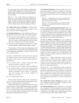
![501.15 ARTICLE 501 — CLASS I LOCATIONS
(D) Cable Seals, Class I, Division 1. In Class I, Division 1 in such a manner as to minimize the passage of gases and
locations, cable seals shall be located according to vapors. Multiconductor cables in conduit shall be sealed as
501.15(D)(1) through (D)(3). described in 501.15(D).
(1) At Terminations. Cable shall be sealed at all termina- Exception No. 1: Cables passing from an enclosure or
tions. The sealing fitting shall comply with 501.15(C). Mul- room that is unclassified as a result of Type Z pressuriza-
ticonductor Type MC-HL cables with a gas/vaportight con- tion into a Class I, Division 2 location shall not require a
tinuous corrugated metallic sheath and an overall jacket of seal at the boundary.
suitable polymeric material shall be sealed with a listed
Exception No. 2: Shielded cables and twisted pair cables
fitting after removing the jacket and any other covering so
shall not require the removal of the shielding material or sepa-
that the sealing compound surrounds each individual insu-
ration of the twisted pairs, provided the termination is by an
lated conductor in such a manner as to minimize the pas-
approved means to minimize the entrance of gases or vapors
sage of gases and vapors.
and prevent propagation of flame into the cable core.
Exception: Shielded cables and twisted pair cables shall not
require the removal of the shielding material or separation of (2) Cables That Do Not Transmit Gases or Vapors.
the twisted pairs, provided the termination is by an approved Cables that have a gas/vaportight continuous sheath and do
means to minimize the entrance of gases or vapors and pre- not transmit gases or vapors through the cable core in excess
vent propagation of flame into the cable core. of the quantity permitted for seal fittings shall not be required
to be sealed except as required in 501.15(E)(1). The minimum
(2) Cables Capable of Transmitting Gases or Vapors. length of such cable run shall not be less than that length that
Cables in conduit with a gas/vaportight continuous sheath limits gas or vapor flow through the cable core to the rate
capable of transmitting gases or vapors through the cable permitted for seal fittings [200 cm3/hr (0.007 ft3/hr) of air at a
core shall be sealed in the Division 1 location after remov- pressure of 1500 pascals (6 in. of water)].
ing the jacket and any other coverings so that the sealing
compound will surround each individual insulated conduc- FPN No. 1: See ANSI/UL 886-1994, Outlet Boxes and
Fittings for Use in Hazardous (Classified) Locations.
tor and the outer jacket.
Exception: Multiconductor cables with a gas/vaportight FPN No. 2: The cable core does not include the interstices
of the conductor strands.
continuous sheath capable of transmitting gases or vapors
through the cable core shall be permitted to be considered (3) Cables Capable of Transmitting Gases or Vapors.
as a single conductor by sealing the cable in the conduit Cables with a gas/vaportight continuous sheath capable of
within 450 mm (18 in.) of the enclosure and the cable end transmitting gases or vapors through the cable core shall not
within the enclosure by an approved means to minimize the be required to be sealed except as required in 501.15(E)(1),
entrance of gases or vapors and prevent the propagation of unless the cable is attached to process equipment or devices
flame into the cable core, or by other approved methods. that may cause a pressure in excess of 1500 pascals (6 in. of
For shielded cables and twisted pair cables, it shall not be water) to be exerted at a cable end, in which case a seal,
required to remove the shielding material or separate the barrier, or other means shall be provided to prevent migration
twisted pair. of flammables into an unclassified location.
(3) Cables Incapable of Transmitting Gases or Vapors. Exception: Cables with an unbroken gas/vaportight con-
Each multiconductor cable in conduit shall be considered as tinuous sheath shall be permitted to pass through a Class I,
a single conductor if the cable is incapable of transmitting Division 2 location without seals.
gases or vapors through the cable core. These cables shall
be sealed in accordance with 501.15(A). (4) Cables Without Gas/Vaportight Sheath. Cables that
do not have gas/vaportight continuous sheath shall be
(E) Cable Seals, Class I, Division 2. In Class I, Division 2 sealed at the boundary of the Division 2 and unclassified
locations, cable seals shall be located in accordance with location in such a manner as to minimize the passage of
501.15(E)(1) through (E)(4). gases or vapors into an unclassified location.
(1) Terminations. Cables entering enclosures that are re- (F) Drainage.
quired to be explosionproof shall be sealed at the point of
entrance. The sealing fitting shall comply with 501.15(B)(1). (1) Control Equipment. Where there is a probability that
Multiconductor cables with a gas/vaportight continuous sheath liquid or other condensed vapor may be trapped within
capable of transmitting gases or vapors through the cable core enclosures for control equipment or at any point in the
shall be sealed in a listed fitting in the Division 2 location after raceway system, approved means shall be provided to pre-
removing the jacket and any other coverings so that the seal- vent accumulation or to permit periodic draining of such
ing compound surrounds each individual insulated conductor liquid or condensed vapor.
70–352 NATIONAL ELECTRICAL CODE 2005 Edition](https://image.slidesharecdn.com/nechandbookversin2005compacta-100921141249-phpapp02/85/Nec-handbook-version-2005-compacta-355-320.jpg)
![501.40 ARTICLE 501 — CLASS I LOCATIONS
501.40 Multiwire Branch Circuits. In a Class I, Division 1 horns shall have enclosures identified for Class I, Division
location, a multiwire branch circuit shall not be permitted. 1 locations in accordance with 501.105(A).
Exception: Where the disconnect device(s) for the circuit Exception: General-purpose enclosures shall be permitted
opens all ungrounded conductors of the multiwire circuit if current-interrupting contacts comply with one of the fol-
simultaneously. lowing:
(1) Are immersed in oil
III. Equipment (2) Are enclosed within a chamber that is hermetically
sealed against the entrance of gases or vapors
501.100 Transformers and Capacitors.
(3) Are in nonincendive circuits
(A) Class I, Division 1. In Class I, Division 1 locations, (4) Are listed for Division 2
transformers and capacitors shall comply with 501.100(A)(1)
and (A)(2). (2) Resistors and Similar Equipment. Resistors, resis-
tance devices, thermionic tubes, rectifiers, and similar
(1) Containing Liquid That Will Burn. Transformers and
equipment that are used in or in connection with meters,
capacitors containing a liquid that will burn shall be in-
instruments, and relays shall comply with 501.105(A).
stalled only in vaults that comply with 450.41 through
450.48 and with (1) through (4) as follows: Exception: General-purpose-type enclosures shall be per-
(1) There shall be no door or other communicating opening mitted if such equipment is without make-and-break or slid-
between the vault and the Division 1 location. ing contacts [other than as provided in 501.105(B)(1)] and
(2) Ample ventilation shall be provided for the continuous if the maximum operating temperature of any exposed sur-
removal of flammable gases or vapors. face will not exceed 80 percent of the ignition temperature
in degrees Celsius of the gas or vapor involved or has been
(3) Vent openings or ducts shall lead to a safe location
tested and found incapable of igniting the gas or vapor.
outside of buildings.
This exception shall not apply to thermionic tubes.
(4) Vent ducts and openings shall be of sufficient area to
relieve explosion pressures within the vault, and all (3) Without Make-or-Break Contacts. Transformer wind-
portions of vent ducts within the buildings shall be of ings, impedance coils, solenoids, and other windings that do
reinforced concrete construction. not incorporate sliding or make-or-break contacts shall be pro-
vided with enclosures. General-purpose-type enclosures shall
(2) Not Containing Liquid That Will Burn. Transform-
be permitted.
ers and capacitors that do not contain a liquid that will burn
shall be installed in vaults complying with 501.100(A)(1) (4) General-Purpose Assemblies. Where an assembly is
or be approved for Class I locations. made up of components for which general-purpose enclo-
sures are acceptable as provided in 501.105(B)(1), (B)(2),
(B) Class I, Division 2. In Class I, Division 2 locations,
and (B)(3), a single general-purpose enclosure shall be ac-
transformers and capacitors shall comply with 450.21
ceptable for the assembly. Where such an assembly in-
through 450.27.
cludes any of the equipment described in 501.105(B)(2),
501.105 Meters, Instruments, and Relays. the maximum obtainable surface temperature of any com-
ponent of the assembly shall be clearly and permanently
(A) Class I, Division 1. In Class I, Division 1 locations, indicated on the outside of the enclosure. Alternatively,
meters, instruments, and relays, including kilowatt-hour equipment shall be permitted to be marked to indicate the
meters, instrument transformers, resistors, rectifiers, and temperature class for which it is suitable, using the tem-
thermionic tubes, shall be provided with enclosures identi- perature class (T Code) of Table 500.8(B).
fied for Class I, Division 1 locations. Enclosures for Class
I, Division 1 locations include explosionproof enclosures (5) Fuses. Where general-purpose enclosures are permitted
and purged and pressurized enclosures. in 501.105(B)(1) through (B)(4), fuses for overcurrent pro-
tection of instrument circuits not subject to overloading in
FPN: See NFPA 496-2003, Standard for Purged and Pres- normal use shall be permitted to be mounted in general-
surized Enclosures for Electrical Equipment.
purpose enclosures if each such fuse is preceded by a
(B) Class I, Division 2. In Class I, Division 2 locations, switch complying with 501.105(B)(1).
meters, instruments, and relays shall comply with
(6) Connections. To facilitate replacements, process con-
501.105(B)(1) through (B)(6).
trol instruments shall be permitted to be connected through
(1) Contacts. Switches, circuit breakers, and make-and- flexible cord, attachment plug, and receptacle, provided all
break contacts of pushbuttons, relays, alarm bells, and of the following conditions apply:
70–354 NATIONAL ELECTRICAL CODE 2005 Edition](https://image.slidesharecdn.com/nechandbookversin2005compacta-100921141249-phpapp02/85/Nec-handbook-version-2005-compacta-357-320.jpg)
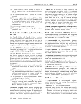
![501.130 ARTICLE 501 — CLASS I LOCATIONS
10 volumes of air, and also arranged to automatically FPN No. 1: It is important to consider the temperature of
de-energize the equipment when the air supply fails internal and external surfaces that may be exposed to the
flammable atmosphere.
(3) Of the totally enclosed inert gas-filled type supplied
with a suitable reliable source of inert gas for pressur- FPN No. 2: It is important to consider the risk of ignition
due to currents arcing across discontinuities and overheat-
izing the enclosure, with devices provided to ensure a ing of parts in multisection enclosures of large motors and
positive pressure in the enclosure and arranged to au- generators. Such motors and generators may need equipo-
tomatically de-energize the equipment when the gas tential bonding jumpers across joints in the enclosure and
supply fails from enclosure to ground. Where the presence of ignitible
gases or vapors is suspected, clean-air purging may be
(4) Of a type designed to be submerged in a liquid that is needed immediately prior to and during start-up periods.
flammable only when vaporized and mixed with air, or
FPN No. 3: For further information on the application of
in a gas or vapor at a pressure greater than atmospheric
electric motors in Class I, Division 2 hazardous (classified)
and that is flammable only when mixed with air; and locations, see IEEE Std. 1349-2001, IEEE Guide for the
the machine is arranged so to prevent energizing it until Application of Electric Motors in Class I, Division 2 Haz-
it has been purged with the liquid or gas to exclude air, ardous (Classified) Locations.
and also arranged to automatically de-energize the
equipment when the supply of liquid or gas or vapor 501.130 Luminaires (Lighting Fixtures). Luminaires
fails or the pressure is reduced to atmospheric (lighting fixtures) shall comply with 501.130(A) or (B).
Totally enclosed motors of the types specified in (A) Class I, Division 1. In Class I, Division 1 locations,
501.125(A)(2) or 501.125(A)(3) shall have no external surface luminaires (lighting fixtures) shall comply with 501.130(A)(1)
with an operating temperature in degrees Celsius in excess of through (A)(4).
80 percent of the ignition temperature of the gas or vapor
involved. Appropriate devices shall be provided to detect and (1) Luminaires (Lighting Fixtures). Each luminaire
automatically de-energize the motor or provide an adequate (lighting fixture) shall be identified as a complete assembly
alarm if there is any increase in temperature of the motor for the Class I, Division 1 location and shall be clearly
beyond designed limits. Auxiliary equipment shall be of a type marked to indicate the maximum wattage of lamps for
identified for the location in which it is installed. which it is identified. Luminaires (lighting fixtures) in-
tended for portable use shall be specifically listed as a com-
FPN: See D 2155-69, ASTM Test Procedure. plete assembly for that use.
(B) Class I, Division 2. In Class I, Division 2 locations, (2) Physical Damage. Each luminaire (lighting fixture)
motors, generators, and other rotating electric machinery in shall be protected against physical damage by a suitable
which are employed sliding contacts, centrifugal or other guard or by location.
types of switching mechanism (including motor overcur-
rent, overloading, and overtemperature devices), or integral (3) Pendant Luminaires (Lighting Fixtures). Pendant lu-
resistance devices, either while starting or while running, minaires (lighting fixtures) shall be suspended by and sup-
shall be identified for Class I, Division 1 locations, unless plied through threaded rigid metal conduit stems or
such sliding contacts, switching mechanisms, and resis- threaded steel intermediate conduit stems, and threaded
tance devices are provided with enclosures identified for joints shall be provided with set-screws or other effective
Class I, Division 2 locations in accordance with means to prevent loosening. For stems longer than 300 mm
501.105(B). The exposed surface of space heaters used to (12 in.), permanent and effective bracing against lateral dis-
prevent condensation of moisture during shutdown periods placement shall be provided at a level not more than
shall not exceed 80 percent of the ignition temperature in 300 mm (12 in.) above the lower end of the stem, or flex-
degrees Celsius of the gas or vapor involved when operated ibility in the form of a fitting or flexible connector identi-
at rated voltage, and the maximum surface temperature fied for the Class I, Division 1 location shall be provided
[based on a 40°C (104°F) ambient] shall be permanently not more than 300 mm (12 in.) from the point of attachment
to the supporting box or fitting.
marked on a visible nameplate mounted on the motor. Oth-
erwise, space heaters shall be identified for Class I, Divi- (4) Supports. Boxes, box assemblies, or fittings used for
sion 2 locations. In Class I, Division 2 locations, the instal- the support of luminaires (lighting fixtures) shall be identi-
lation of open or nonexplosionproof enclosed motors, such fied for Class I locations.
as squirrel-cage induction motors without brushes, switch-
ing mechanisms, or similar arc-producing devices that are (B) Class I, Division 2. In Class I, Division 2 locations,
not identified for use in a Class I, Division 2 location, shall luminaires (lighting fixtures) shall comply with
be permitted. 501.130(B)(1) through 501.130(B)(6).
70–356 NATIONAL ELECTRICAL CODE 2005 Edition](https://image.slidesharecdn.com/nechandbookversin2005compacta-100921141249-phpapp02/85/Nec-handbook-version-2005-compacta-359-320.jpg)
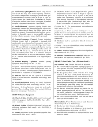
![505.2 ARTICLE 505 — CLASS I, ZONE 0, 1, AND 2 LOCATIONS
Electrical and Electronic Equipment. Materials, fittings, FPN No. 3: Intrinsically safe associated apparatus, desig-
devices, appliances, and the like that are part of, or in connec- nated by [ia] or [ib], is connected to intrinsically safe ap-
tion with, an electrical installation. paratus (“ia” or “ib,” respectively) but is located outside the
hazardous (classified) location unless also protected by an-
FPN: Portable or transportable equipment having self- other type of protection (such as flameproof).
contained power supplies, such as battery-operated equipment,
could potentially become an ignition source in hazardous Oil Immersion “o.” Type of protection where electrical
(classified) locations. equipment is immersed in a protective liquid in such a way
that an explosive atmosphere that may be above the liquid
Encapsulation “m.” Type of protection where electrical
or outside the enclosure cannot be ignited.
parts that could ignite an explosive atmosphere by either
sparking or heating are enclosed in a compound in such a FPN: See ISA 12.26.01-1998, Electrical Apparatus for Use
way that this explosive atmosphere cannot be ignited. in Class I, Zone 1 Hazardous (Classified) Locations, Type of
Protection — Oil-Immersion “o”; and ANSI/UL 60079-6,
FPN: See ANSI/ISA 12.23.01-2002, Electrical Apparatus Electrical apparatus for explosive gas atmospheres — Part 6:
for Use in Class I, Zone 1 Hazardous (Classified) Locations, Oil-immersion “o.”
Type of Protection — Encapsulation “m”; and ANSI/UL
60079–18, Electrical apparatus for explosive gas atmospheres Powder Filling “q.” Type of protection where electrical
— Part 18: Encapsulation “m.” parts capable of igniting an explosive atmosphere are fixed
Flameproof “d.” Type of protection where the enclosure in position and completely surrounded by filling material
will withstand an internal explosion of a flammable mixture (glass or quartz powder) to prevent the ignition of an ex-
that has penetrated into the interior, without suffering dam- ternal explosive atmosphere.
age and without causing ignition, through any joints or
FPN: See ANSI/ISA-12.25.01-2002, Electrical Apparatus
structural openings in the enclosure, of an external explo- for Use in Class I, Zone 1 Hazardous (Classified) Locations
sive gas atmosphere consisting of one or more of the gases Type of Protection — Powder Filling “q”; and ANSI/UL
or vapors for which it is designed. 60079-5, Electrical apparatus for explosive gas atmo-
spheres — Part 5: Powder filling “q.”
FPN: See ANSI/ISA 12.22.01-2002, Electrical Apparatus
for Use in Class I, Zone 1 and 2 Hazardous (Classified) Purged and Pressurized. Type of protection for electrical
Locations, Type of Protection — Flameproof “d”; and
equipment that uses the technique of guarding against the
ANSI/UL 60079–1, Electrical apparatus for explosive gas
atmospheres — Part 1: Flameproof enclosures “d.” ingress of the external atmosphere, which may be explo-
sive, into an enclosure by maintaining a protective gas
Increased Safety “e.” Type of protection applied to electri- therein at a pressure above that of the external atmosphere.
cal equipment that does not produce arcs or sparks in normal
service and under specified abnormal conditions, in which ad- FPN No. 1: See NFPA 496-2003, Standard for Purged and
ditional measures are applied so as to give increased security Pressurized Enclosures for Electrical Equipment.
against the possibility of excessive temperatures and of the FPN No. 2: See IEC 60079-2-2000, Electrical Apparatus
occurrence of arcs and sparks. for Explosive Gas Atmospheres — Part 2: Electrical Appa-
ratus, Type of Protection “p”; and IEC 60079-13-1982,
FPN: See ANSI/ISA — 12.16.01-2002, Electrical Appa- Electrical Apparatus for Explosive Gas Atmospheres —
ratus for Use in Class I, Zone 1 Hazardous (Classified) Part 13: Construction and Use of Rooms or Buildings Pro-
Locations, Type of Protection — Increased Safety “e”; and tected by Pressurization.
ANSI/UL 60079-7, Electrical apparatus for explosive gas
atmospheres — Part 7: Increased Safety “e.” Type of Protection “n.” Type of protection where electri-
Intrinsic Safety “i.” Type of protection where any spark or cal equipment, in normal operation, is not capable of ignit-
thermal effect is incapable of causing ignition of a mixture ing a surrounding explosive gas atmosphere and a fault
of flammable or combustible material in air under pre- capable of causing ignition is not likely to occur.
scribed test conditions. FPN: See ANSI/UL 60079-15-2002, Electrical apparatus
for explosive gas atmospheres — Part 15: Type of protection
FPN No. 1: See ANSI/UL 913-1997, Intrinsically Safe
Apparatus and Associated Apparatus for Use in Class I, II, “n”; and ANSI/ISA 12.12.02-2003, Electrical apparatus for
and III, Hazardous Locations; ISA 12.02.01-1999, Electri- use in Class I, Zone 2 Hazardous (Classified) Locations: Type
cal Apparatus for Use in Class I, Zones 0, 1 and 2 Hazard- of protection “n.”
ous (Classified) Locations — Intrinsic Safety “i”; and
ANSI/UL 60079-11, Electrical apparatus for explosive gas Unclassified Locations. Locations determined to be neither
atmospheres — Part II: Intrinsic safety “i.” Class I, Division 1; Class I, Division 2; Class I, Zone 0; Class
FPN No. 2: Intrinsic safety is designated type of protection
I, Zone 1; Class I, Zone 2; Class II, Division 1; Class II,
“ia” for use in Zone 0 locations. Intrinsic safety is designated Division 2; Class III, Division 1; Class III, Division 2; or any
type of protection “ib” for use in Zone 1 locations. combination thereof.
70–370 NATIONAL ELECTRICAL CODE 2005 Edition](https://image.slidesharecdn.com/nechandbookversin2005compacta-100921141249-phpapp02/85/Nec-handbook-version-2005-compacta-373-320.jpg)
![505.5 ARTICLE 505 — CLASS I, ZONE 0, 1, AND 2 LOCATIONS
(B) Class I, Zone 0, 1, and 2 Locations. Class I, Zone 0, 1, (4) That is adjacent to a Class I, Zone 0 location from which
and 2 locations are those in which flammable gases or vapors ignitible concentrations of vapors could be communi-
are or may be present in the air in quantities sufficient to cated, unless communication is prevented by adequate
produce explosive or ignitible mixtures. Class I, Zone 0, 1, positive pressure ventilation from a source of clean air
and 2 locations shall include those specified in 505(B)(1), and effective safeguards against ventilation failure are
(B)(2), and (B)(3). provided.
(1) Class I, Zone 0. A Class I, Zone 0 location is a location FPN No. 1: Normal operation is considered the situation
in which when plant equipment is operating within its design param-
eters. Minor releases of flammable material may be part of
(1) Ignitible concentrations of flammable gases or vapors
normal operations. Minor releases include the releases from
are present continuously, or mechanical packings on pumps. Failures that involve repair
(2) Ignitible concentrations of flammable gases or vapors or shutdown (such as the breakdown of pump seals and
are present for long periods of time. flange gaskets, and spillage caused by accidents) are not
considered normal operation.
FPN No. 1: As a guide in determining when flammable
FPN No. 2: This classification usually includes locations
gases or vapors are present continuously or for long periods of
where volatile flammable liquids or liquefied flammable
time, refer to ANSI/API RP 505-1997, Recommended Prac-
gases are transferred from one container to another. In areas
tice for Classification of Locations for Electrical Installations
in the vicinity of spraying and painting operations where
of Petroleum Facilities Classified as Class I, Zone 0, Zone 1
flammable solvents are used; adequately ventilated drying
or Zone 2; ISA 12.24.01-1998, Recommended Practice for
rooms or compartments for evaporation of flammable sol-
Classification of Locations for Electrical Installations Classi-
fied as Class I, Zone 0, Zone 1, or Zone 2; IEC 60079-10- vents; adequately ventilated locations containing fat and oil
1995, Electrical Apparatus for Explosive Gas Atmospheres, extraction equipment using volatile flammable solvents;
Classifications of Hazardous Areas; and Area Classification portions of cleaning and dyeing plants where volatile flam-
Code for Petroleum Installations, Model Code, Part 15, Insti- mable liquids are used; adequately ventilated gas generator
tute of Petroleum. rooms and other portions of gas manufacturing plants
where flammable gas may escape; inadequately ventilated
FPN No. 2: This classification includes locations inside pump rooms for flammable gas or for volatile flammable
vented tanks or vessels that contain volatile flammable liq- liquids; the interiors of refrigerators and freezers in which
uids; inside inadequately vented spraying or coating enclo- volatile flammable materials are stored in the open, lightly
sures, where volatile flammable solvents are used; between stoppered, or in easily ruptured containers; and other loca-
the inner and outer roof sections of a floating roof tank tions where ignitible concentrations of flammable vapors or
containing volatile flammable liquids; inside open vessels, gases are likely to occur in the course of normal operation
tanks and pits containing volatile flammable liquids; the but not classified Zone 0.
interior of an exhaust duct that is used to vent ignitible
concentrations of gases or vapors; and inside inadequately (3) Class I, Zone 2. A Class I, Zone 2 location is a location
ventilated enclosures that contain normally venting instru-
(1) In which ignitible concentrations of flammable gases or
ments utilizing or analyzing flammable fluids and venting
to the inside of the enclosures. vapors are not likely to occur in normal operation and,
if they do occur, will exist only for a short period; or
FPN No. 3: It is not good practice to install electrical equip-
ment in Zone 0 locations except when the equipment is essen- (2) In which volatile flammable liquids, flammable gases, or
tial to the process or when other locations are not feasible. flammable vapors are handled, processed, or used but in
[See 505.5(A) FPN No. 2.] If it is necessary to install electrical which the liquids, gases, or vapors normally are confined
systems in a Zone 0 location, it is good practice to install within closed containers of closed systems from which
intrinsically safe systems as described by Article 504.
they can escape, only as a result of accidental rupture or
(2) Class I, Zone 1. A Class I, Zone 1 location is a location breakdown of the containers or system, or as a result of
(1) In which ignitible concentrations of flammable gases or the abnormal operation of the equipment with which the
vapors are likely to exist under normal operating condi- liquids or gases are handled, processed, or used; or
tions; or (3) In which ignitible concentrations of flammable gases or
(2) In which ignitible concentrations of flammable gases or vapors normally are prevented by positive mechanical
vapors may exist frequently because of repair or main- ventilation but which may become hazardous as a re-
tenance operations or because of leakage; or sult of failure or abnormal operation of the ventilation
(3) In which equipment is operated or processes are carried equipment; or
on, of such a nature that equipment breakdown or (4) That is adjacent to a Class I, Zone 1 location, from
faulty operations could result in the release of ignitible which ignitible concentrations of flammable gases or
concentrations of flammable gases or vapors and also vapors could be communicated, unless such communi-
cause simultaneous failure of electrical equipment in a cation is prevented by adequate positive-pressure ven-
mode to cause the electrical equipment to become a tilation from a source of clean air and effective safe-
source of ignition; or guards against ventilation failure are provided.
70–372 NATIONAL ELECTRICAL CODE 2005 Edition](https://image.slidesharecdn.com/nechandbookversin2005compacta-100921141249-phpapp02/85/Nec-handbook-version-2005-compacta-375-320.jpg)
![ARTICLE 505 — CLASS I, ZONE 0, 1, AND 2 LOCATIONS 505.7
FPN: The Zone 2 classification usually includes locations that may burn or explode, having either maximum experi-
where volatile flammable liquids or flammable gases or mental safe gap (MESG) values greater than 0.50 mm and
vapors are used but which would become hazardous only in
less than or equal to 0.90 mm or minimum igniting current
case of an accident or of some unusual operating condition.
ratio (MIC ratio) greater than 0.45 and less than or equal to
505.6 Material Groups. For purposes of testing, approval, 0.80. [NFPA 497:3.3]
and area classification, various air mixtures (not oxygen en- FPN: Group IIB is equivalent to Class I, Group C, as
riched) shall be grouped as required in 505.6(A), (B), and (C). described in 500.6(A)(3).
FPN: Group I is intended for use in describing atmospheres (C) Group IIA. Atmospheres containing acetone, ammonia,
that contain firedamp (a mixture of gases, composed mostly of ethyl alcohol, gasoline, methane, propane, or flammable gas,
methane, found underground, usually in mines). This Code flammable liquid-produced vapor, or combustible liquid-
does not apply to installations underground in mines. See produced vapor mixed with air that may burn or explode,
90.2(B). having either a maximum experiment safe gap (MESG) value
Group II shall be subdivided into IIC, IIB, and IIA, as greater than 0.90 mm or minimum igniting current ratio (MIC
noted in 505.6(A), (B), and (C), according to the nature of ratio) greater than 0.80. [NFPA 497:3.3]
the gas or vapor, for protection techniques “d,” “ia,” “ib,” FPN: Group IIA is equivalent to Class I, Group D as
“[ia],” and “[ib],” and, where applicable, “n” and “o.” described in 500.6(A)(4).
FPN No. 1: The gas and vapor subdivision as described 505.7 Special Precaution. Article 505 requires equipment
above is based on the maximum experimental safe gap construction and installation that ensures safe performance
(MESG), minimum igniting current (MIC), or both. Test
equipment for determining the MESG is described in IEC
under conditions of proper use and maintenance.
60079-1A-1975, Amendment No. 1 (1993), Construction FPN No. 1: It is important that inspection authorities and
and Verification Tests of Flameproof Enclosures of Electri- users exercise more than ordinary care with regard to the
cal Apparatus; and UL Technical Report No. 58 (1993). installation and maintenance of electrical equipment in haz-
The test equipment for determining MIC is described in ardous (classified) locations.
IEC 60079-11-1999, Electrical Apparatus for Explosive
Gas Atmospheres — Part 11: Intrinsic Safety “i.” The clas- FPN No. 2: Low ambient conditions require special consid-
sification of gases or vapors according to their maximum eration. Electrical equipment depending on the protection
experimental safe gaps and minimum igniting currents is techniques described by 505.8(A) may not be suitable for use
described in IEC 60079-12-1978, Classification of Mixtures at temperatures lower than −20°C (−4°F) unless they are iden-
of Gases or Vapours with Air According to Their Maximum tified for use at lower temperatures. However, at low ambient
Experimental Safe Gaps and Minimum Igniting Currents. temperatures, flammable concentrations of vapors may not ex-
ist in a location classified Class I, Zones 0, 1, or 2 at normal
FPN No. 2: Verification of electrical equipment utilizing ambient temperature.
protection techniques “e,” “m,” “p,” and “q,” due to design
technique, does not require tests involving MESG or MIC. (A) Supervision of Work. Classification of areas and se-
Therefore, Group II is not required to be subdivided for lection of equipment and wiring methods shall be under the
these protection techniques. supervision of a qualified Registered Professional Engineer.
FPN No. 3: It is necessary that the meanings of the dif-
ferent equipment markings and Group II classifications be (B) Dual Classification. In instances of areas within the
carefully observed to avoid confusion with Class I, Divi- same facility classified separately, Class I, Zone 2 locations
sions 1 and 2, Groups A, B, C, and D. shall be permitted to abut, but not overlap, Class I, Division 2
locations. Class I, Zone 0 or Zone 1 locations shall not abut
Class I, Zone 0, 1, and 2, groups shall be as follows:
Class I, Division 1 or Division 2 locations.
(A) Group IIC. Atmospheres containing acetylene, hydro- (C) Reclassification Permitted. A Class I, Division 1 or
gen, or flammable gas, flammable liquid-produced vapor, Division 2 location shall be permitted to be reclassified as a
or combustible liquid-produced vapor mixed with air that Class I, Zone 0, Zone 1, or Zone 2 location, provided all of
may burn or explode, having either a maximum experimen- the space that is classified because of a single flammable
tal safe gap (MESG) value less than or equal to 0.50 mm or gas or vapor source is reclassified under the requirements
minimum igniting current ratio (MIC ratio) less than or of this article.
equal to 0.45. [NFPA 497:3.3]
(D) Solid Obstacles. Flameproof equipment with flanged
FPN: Group IIC is equivalent to a combination of Class I, joints shall not be installed such that the flange openings
Group A, and Class I, Group B, as described in 500.6(A)(1)
and 500.6(A)(2). are closer than the distances shown in Table 505.7(D) to
any solid obstacle that is not a part of the equipment (such
(B) Group IIB. Atmospheres containing acetaldehyde, as steelworks, walls, weather guards, mounting brackets,
ethylene, or flammable gas, flammable liquid-produced va- pipes, or other electrical equipment) unless the equipment
por, or combustible liquid-produced vapor mixed with air is listed for a smaller distance of separation.
2005 Edition NATIONAL ELECTRICAL CODE 70–373](https://image.slidesharecdn.com/nechandbookversin2005compacta-100921141249-phpapp02/85/Nec-handbook-version-2005-compacta-376-320.jpg)
![ARTICLE 505 — CLASS I, ZONE 0, 1, AND 2 LOCATIONS 505.9
(2) Equipment shall be permitted to be listed for a specific Table 505.9(C)(2)(4) Types of Protection Designation
gas or vapor, specific mixtures of gases or vapors, or
any specific combination of gases or vapors. Designation Technique Zone*
FPN: One common example is equipment marked for d Flameproof enclosure 1
“IIB. + H2.” e Increased safety 1
ia Intrinsic safety 0
ib Intrinsic safety 1
(C) Marking. Equipment shall be marked in accordance [ia] Associated apparatus Unclassified
with 505.9(C)(1) or (C)(2). [ib] Associated apparatus Unclassified
m Encapsulation 1
(1) Division Equipment. Equipment identified for Class I, nA Nonsparking equipment 2
Division 1 or Class I, Division 2 shall, in addition to being nC Sparking equipment in 2
marked in accordance with 500.8(B), be permitted to be which the contacts are
marked with all of the following: suitably protected
other than by
(1) Class I, Zone 1 or Class I, Zone 2 (as applicable) restricted breathing
(2) Applicable gas classification group(s) in accordance enclosure
with Table 505.9(C) nR Restricted breathing 2
enclosure
(3) Temperature classification in accordance with 505.9(D)(1) o Oil immersion 1
p Purged and pressurized 1 or 2
Table 505.9(C) Gas Classification Groups q Powder filled 1
*Does not address use where a combination of techniques is used.
Gas Group Comment
be marked Group II unless it contains enclosed-break de-
IIC See 505.6(A)(1)
IIB See 505.6(A)(2) vices, nonincendive components, or energy-limited equip-
IIA See 505.6(A)(3) ment or circuits, in which case it shall be marked Group
IIA, IIB, or IIC, or a specific gas or vapor. Electrical equip-
ment of other types of protection shall be marked Group II
(2) Zone Equipment. Equipment meeting one or more of unless the type of protection utilized by the equipment re-
the protection techniques described in 505.8 shall be quires that it be marked Group IIA, IIB, or IIC, or a specific
marked with all of the following in the order shown: gas or vapor.
(1) Class
FPN No. 1: An example of the required marking for intrin-
(2) Zone sically safe apparatus for installation in Class I, Zone 0 is
(3) Symbol “AEx” “Class I, Zone 0, AEx ia IIC T6.” An explanation of the mark-
ing that is required is shown in FPN Figure 505.9(C)(2).
(4) Protection technique(s) in accordance with Table
505.9(C)(2)(4) FPN No. 2: An example of the required marking for intrin-
sically safe associated apparatus mounted in a flameproof en-
(5) Applicable gas classification group(s) in accordance closure for installation in Class I, Zone 1 is “Class I, Zone 1
with Table 505.9(C) AEx d[ia] IIC T4.”
(6) Temperature classification in accordance with 505.9(D)(1) FPN No. 3: An example of the required marking for in-
trinsically safe associated apparatus NOT for installation in
Exception No. 1: Associated apparatus NOT suitable for a hazardous (classified) location is “[AEx ia] IIC.”
installation in a hazardous (classified) locations shall be
required to be marked only with (3), (4), and (5), but BOTH
the symbol AEx (3) and the symbol for the type of protec- Example: Class I Zone 0 AEx ia IIC T6
tion (4) shall be enclosed within the same square brackets,
for example, [AEx ia] IIC. Area classification
Exception No. 2: Simple apparatus as defined in 504.2 Symbol for equipment built to American
shall not be required to have a marked operating tempera- standards
ture or temperature class. Type(s) of protection designation
Electrical equipment of types of protection “e,” “m,” Gas classification group (not required for protection
“p,” or “q” shall be marked Group II. Electrical equipment techniques indicated in 505.6, FPN No. 2)
of types of protection “d,” “ia,” “ib,” “[ia],” or “[ib]” shall Temperature classification
be marked Group IIA, IIB, or IIC, or for a specific gas or
vapor. Electrical equipment of types of protection “n” shall FPN Figure 505.9(C)(2) Zone Equipment Marking.
2005 Edition NATIONAL ELECTRICAL CODE 70–375](https://image.slidesharecdn.com/nechandbookversin2005compacta-100921141249-phpapp02/85/Nec-handbook-version-2005-compacta-378-320.jpg)
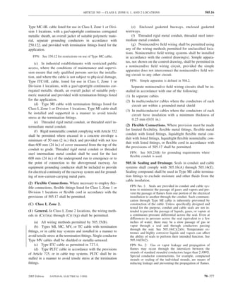
![505.16 ARTICLE 505 — CLASS I, ZONE 0, 1, AND 2 LOCATIONS
(2) Cable Seals. Cable seals shall be located in accordance FPN: The cable sheath may be either metal or a nonme-
with (C)(2)(a), (C)(2)(b), and (C)(2)(c). tallic material.
(a) Explosionproof and Flameproof Enclosures. Cables (D) Class I, Zones 0, 1, and 2. Where required, seals in
entering enclosures required to be flameproof or explosion- Class I, Zones 0, 1, and 2 locations shall comply with
proof shall be sealed at the point of entrance. The seal shall 505.16(D)(1) through (D)(5).
comply with 505.16(D). Multiconductor cables with a
gas/vaportight continuous sheath capable of transmitting (1) Fittings. Enclosures for connections or equipment shall
gases or vapors through the cable core shall be sealed in the be provided with an integral means for sealing, or sealing
Zone 2 location after removing the jacket and any other cov- fittings listed for the location shall be used. Sealing fittings
erings so that the sealing compound surrounds each individual shall be listed for use with one or more specific compounds
insulated conductor in such a manner as to minimize the pas- and shall be accessible.
sage of gases and vapors. Multiconductor cables in conduit (2) Compound. The compound shall provide a seal against
shall be sealed as described in 505.16(B)(4). passage of gas or vapors through the seal fitting, shall not
Exception No. 1: Cables passing from an enclosure or be affected by the surrounding atmosphere or liquids, and
room that is unclassified as a result of Type Z pressuriza- shall not have a melting point less than 93°C (200°F).
tion into a Class I, Zone 2 location shall not require a seal
(3) Thickness of Compounds. In a completed seal, the
at the boundary.
minimum thickness of the sealing compound shall not be
Exception No. 2: Shielded cables and twisted pair cables less than the trade size of the sealing fitting and, in no case,
shall not require the removal of the shielding material or sepa- less than 16 mm (5⁄8 in.).
ration of the twisted pairs, provided the termination is by an
approved means to minimize the entrance of gases or vapors Exception: Listed cable sealing fittings shall not be re-
and prevent propagation of flame into the cable core. quired to have a minimum thickness equal to the trade size
(b) Cables That Will Not Transmit Gases or Vapors. of the fitting.
Cables with a gas/vaportight continuous sheath and that will (4) Splices and Taps. Splices and taps shall not be made in
not transmit gases or vapors through the cable core in excess fittings intended only for sealing with compound, nor shall
of the quantity permitted for seal fittings shall not be required other fittings in which splices or taps are made be filled
to be sealed except as required in 505.16(C)(2)(a). The mini- with compound.
mum length of such cable run shall not be less than the length
that limits gas or vapor flow through the cable core to the rate (5) Conductor Fill. The cross-sectional area of the con-
permitted for seal fittings [200 cm3/hr (0.007 ft3/hr) of air at a ductors permitted in a seal shall not exceed 25 percent of
pressure of 1500 pascals (6 in. of water)]. the cross-sectional area of a rigid metal conduit of the same
trade size unless it is specifically listed for a higher percent-
FPN No. 1: See ANSI/UL 886-1994, Outlet Boxes and
age of fill.
Fittings for Use in Hazardous (Classified) Locations.
FPN No. 2: The cable core does not include the interstices (E) Drainage.
of the conductor strands.
(1) Control Equipment. Where there is a probability that
(c) Cables Capable of Transmitting Gases or Vapors. liquid or other condensed vapor may be trapped within
Cables with a gas/vaportight continuous sheath capable of enclosures for control equipment or at any point in the
transmitting gases or vapors through the cable core shall not raceway system, approved means shall be provided to pre-
be required to be sealed except as required in 505.16(C)(2)(a), vent accumulation or to permit periodic draining of such
unless the cable is attached to process equipment or devices liquid or condensed vapor.
that may cause a pressure in excess of 1500 pascals (6 in. of
water) to be exerted at a cable end, in which case a seal, (2) Motors and Generators. Where the authority having
barrier, or other means shall be provided to prevent migration jurisdiction judges that there is a probability that liquid or
of flammables into an unclassified area. condensed vapor may accumulate within motors or genera-
Exception: Cables with an unbroken gas/vaportight con- tors, joints and conduit systems shall be arranged to mini-
tinuous sheath shall be permitted to pass through a Class I, mize entrance of liquid. If means to prevent accumulation
Zone 2 location without seals. or to permit periodic draining are judged necessary, such
means shall be provided at the time of manufacture and
(d) Cables Without Gas/Vaportight Continuous Sheath.
shall be considered an integral part of the machine.
Cables that do not have gas/vaportight continuous sheath
shall be sealed at the boundary of the Zone 2 and unclassi- (3) Canned Pumps, Process, or Service Connections,
fied location in such a manner as to minimize the passage and So Forth. For canned pumps, process, or service con-
of gases or vapors into an unclassified location. nections for flow, pressure, or analysis measurement, and
70–380 NATIONAL ELECTRICAL CODE 2005 Edition](https://image.slidesharecdn.com/nechandbookversin2005compacta-100921141249-phpapp02/85/Nec-handbook-version-2005-compacta-383-320.jpg)

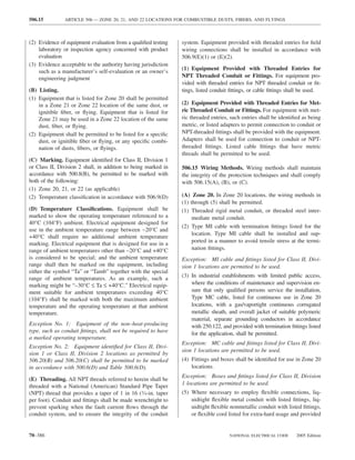
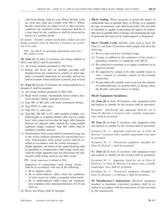
![ARTICLE 511 — COMMERCIAL GARAGES, REPAIR AND STORAGE 511.3
FPN: For further information, see NFPA 88A-2002, Stan- FPN: For further information on the definition of major
dard for Parking Structures, and NFPA 30A-2003, Code for repair garage, see 3.3.12.1 of NFPA 30A-2003, Code for
Motor Fuel Dispensing Facilities and Repair Garages. Motor Fuel Dispensing Facilities and Repair Garages.
(2) Alcohol-Based Windshield Washer Fluid. The stor- (B) Classified Locations.
age, handling, or dispensing into motor vehicles of alcohol-
based windshield washer fluid in areas used for the service (1) Flammable Fuel Dispensing Areas. Areas in which
and repair operations of the vehicles shall not cause such flammable fuel is dispensed into vehicle fuel tanks shall
areas to be classified as hazardous (classified) locations. conform to Article 514.
FPN: For further information, see 8.3.5, Exception, of (2) Lubrication or Service Room Where Class I Liquids
NFPA 30A-2003, Code for Motor Fuel Dispensing Facili- or Gaseous Fuels (Such as Natural Gas, Hydrogen, or
ties and Repair Garages.
LPG) Are Not Transferred. The following spaces that are
(3) Specific Areas Adjacent to Classified Locations. Ar- not designed in accordance with 511.3(A)(4) shall be clas-
eas adjacent to classified locations in which flammable va- sified as Class I, Division 2:
pors are not likely to be released, such as stock rooms, (1) Entire area within any unventilated pit, belowgrade work
switchboard rooms, and other similar locations, shall not be area, or subfloor area.
classified where mechanically ventilated at a rate of four or (2) Area up to 450 mm (18 in.) above any such unventi-
more air changes per hour, or designed with positive air lated pit, belowgrade work area, or subfloor work area
pressure, or where effectively cut off by walls or partitions. and extending a distance of 900 mm (3 ft) horizontally
from the edge of any such pit, belowgrade work area,
(4) Pits in Lubrication or Service Room Where Class I
or subfloor work area.
Liquids Are Not Transferred. Any pit, belowgrade work
area, or subfloor work area that is provided with exhaust ven- (3) Lubrication or Service Room Where Class I Liquids
tilation at a rate of not less than 0.3 m3/min/m2 (1 cfm/ft2) of or Gaseous Fuels (Such as Natural Gas, Hydrogen, or
floor area at all times that the building is occupied or when LPG) Are Transferred. The following spaces that are not
vehicles are parked in or over this area and where exhaust air designed in accordance with 511.3(A)(5) shall be classified
is taken from a point within 300 mm (12 in.) of the floor of the as follows:
pit, belowgrade work area, or subfloor work area is unclassi-
(1) Up to a Level of 450 mm (18 in.) Above the Floor. For
fied. [NFPA 30A:7.4.5.4 and Table 8.3.1]
each floor, the entire area up to a level of 450 mm (18 in.)
(5) Up to a Level of 450 mm (18 in.) Above the Floor in above the floor shall be a Class I, Division 2 location.
Lubrication or Service Rooms Where Class I Liquids Are (2) Any Unventilated Pit or Depression Below Floor Level.
Transferred. For each floor, the entire area up to a level of Any unventilated pit or depression below floor level shall
450 mm (18 in.) above the floor shall be considered unclas- be a Class I, Division 1 location and shall extend up to
sified where there is mechanical ventilation providing a said floor level.
minimum of four air changes per hour or one cubic foot per (3) Any Ventilated Pit or Depression Below Floor Level. Any
minute of exchanged air for each square foot of floor area. ventilated pit or depression in which six air changes per
Ventilation shall provide for air exchange across the entire hour are exhausted from a point within 300 mm (12 in.)
floor area, and exhaust air shall be taken at a point within of the floor level of the pit shall be a Class I, Division 2
0.3 m (12 in.) of the floor. location.
(6) Flammable Liquids Having Flash Points Below 38°C (4) Space Above an Unventilated Pit or Depression Below
(100°F). Where flammable liquids having a flash point be- Floor Level. Above a pit, or depression below floor
low 38°C (100°F) (such as gasoline) or gaseous fuels (such level, the space up to 450 mm (18 in.) above the floor
as natural gas, hydrogen, or LPG) will not be transferred, or grade level and 900 mm (3 ft) horizontally from a
such location shall be considered to be unclassified. unless lubrication pit shall be a Class I, Division 2 location.
the location is required to be classified in accordance with (5) Dispenser for Class I Liquids, Other Than Fuels.
511.3(B)(2) or (B)(4). Within 900 mm (3 ft) of any fill or dispensing point,
extending in all directions shall be a Class I, Division 2
(7) Within 450 mm (18 in.) of the Ceiling. In major re- location. See also 511.3(B)(1).
pair garages, where lighter-than-air gaseous fuels (such as
natural gas or hydrogen) vehicles are repaired or stored, the (4) Within 450 mm (18 in.) of the Ceiling. In major re-
area within 450 mm (18 in.) of the ceiling shall be consid- pair garages where lighter-than-air gaseous fuel (such as
ered unclassified where ventilation of at least 1 cfm/sq ft of natural gas or hydrogen) vehicles are repaired or stored,
ceiling area taken from a point within 450 mm (18 in.) of ceiling spaces that are not designed in accordance with
the highest point in the ceiling is provided. 511.3(A)(7) shall be classified as Class I, Division 2.
2005 Edition NATIONAL ELECTRICAL CODE 70–389](https://image.slidesharecdn.com/nechandbookversin2005compacta-100921141249-phpapp02/85/Nec-handbook-version-2005-compacta-392-320.jpg)
![514.2 ARTICLE 514 — MOTOR FUEL DISPENSING FACILITIES
514.2 Definition. Class I, Div. 1
Class I, Div. 2
Motor Fuel Dispensing Facility. That portion of a prop-
erty where motor fuels are stored and dispensed from fixed Dispensing area 6.0 m (20 ft)
450 mm
equipment into the fuel tanks of motor vehicles or marine (18 in.)
craft or into approved containers, including all equipment 450 mm
(18 in.)
used in connection therewith. [NFPA 30A:3.3.11] 450 mm
FPN: Refer to Articles 510 and 511 with respect to electric (18 in.)
wiring and equipment for other areas used as lubritoriums,
service rooms, repair rooms, offices, salesrooms, compres-
sor rooms, and similar locations.
514.3 Classification of Locations.
(A) Unclassified Locations. Where the authority having ju- 6.0 m (20 ft) 6.0 m (20 ft)
risdiction can satisfactorily determine that flammable liq-
uids having a flash point below 38°C (100°F), such as gaso-
line, will not be handled, such location shall not be required Dispensers
to be classified.
(B) Classified Locations. 6.0 m 6.0 m
(20 ft) (20 ft)
(1) Class I Locations. Table 514.3(B)(1) shall be applied
where Class I liquids are stored, handled, or dispensed and
shall be used to delineate and classify motor fuel dispens-
ing facilities and commercial garages as defined in Article
Figure 514.3 Classified Areas Adjacent to Dispensers as De-
511. Table 515.3 shall be used for the purpose of delineat- tailed in Table 514.3(B)(1). [NFPA 30A:Figure 8.3.1]
ing and classifying aboveground tanks. A Class I location
shall not extend beyond an unpierced wall, roof, or other
solid partition. [NFPA 30A:8.1, 8.3] FPN: For special requirements for conductor insulation,
(2) Compressed Natural Gas, Liquefied Natural Gas, see 501.20.
and Liquefied Petroleum Gas Areas. Table 514.3(B)(2)
shall be used to delineate and classify areas where com- 514.7 Wiring and Equipment Above Class I Locations.
pressed natural gas (CNG), liquefied natural gas (LNG), Wiring and equipment above the Class I locations as clas-
or liquefied petroleum gas (LPG) are stored, handled, or sified in 514.3 shall comply with 511.7.
dispensed. Where CNG or LNG dispensers are installed
beneath a canopy or enclosure, either the canopy or the 514.8 Underground Wiring. Underground wiring shall be
enclosure shall be designed to prevent accumulation or installed in threaded rigid metal conduit or threaded steel in-
entrapment of ignitible vapors, or all electrical equip- termediate metal conduit. Any portion of electrical wiring that
ment installed beneath the canopy or enclosure shall be is below the surface of a Class I, Division 1, or a Class I,
suitable for Class I, Division 2 hazardous (classified) Division 2, location [as classified in Table 514.3(B)(1) and
locations. Dispensing devices for liquefied petroleum gas Table 514.3(B)(2)] shall be sealed within 3.05 m (10 ft) of the
shall be located not less than 1.5 m (5 ft) from any point of emergence above grade. Except for listed explosion-
dispensing device for Class I liquids. [NFPA 30A:12.1, proof reducers at the conduit seal, there shall be no union,
12.4, 12.5] coupling, box, or fitting between the conduit seal and the point
of emergence above grade. Refer to Table 300.5.
FPN No. 1: For information on area classification where
liquefied petroleum gases are dispensed, see NFPA 58- Exception No. 1: Type MI cable shall be permitted where
2004, Liquefied Petroleum Gas Code.
it is installed in accordance with Article 332.
FPN No. 2: For information on classified areas pertaining
to LP-Gas systems other than residential or commercial, Exception No. 2: Rigid nonmetallic conduit shall be per-
see NFPA 58-2004, Liquefied Petroleum Gas Code, and mitted where buried under not less than 600 mm (2 ft) of
NFPA 59-2004, Utility LP-Gas Plant Code. cover. Where rigid nonmetallic conduit is used, threaded
FPN No. 3: See 555.21 for motor fuel dispensing stations rigid metal conduit or threaded steel intermediate metal
in marinas and boatyards. conduit shall be used for the last 600 mm (2 ft) of the
14.4 Wiring and Equipment Installed in Class I Loca- underground run to emergence or to the point of connection
tions. All electrical equipment and wiring installed in Class I to the aboveground raceway, and an equipment grounding
locations as classified in 514.3 shall comply with the appli- conductor shall be included to provide electrical continuity
cable provisions of Article 501. of the raceway system and for grounding of non–current-
Exception: As permitted in 514.8. carrying metal parts.
70–394 NATIONAL ELECTRICAL CODE 2005 Edition](https://image.slidesharecdn.com/nechandbookversin2005compacta-100921141249-phpapp02/85/Nec-handbook-version-2005-compacta-397-320.jpg)
![514.8 ARTICLE 514 — MOTOR FUEL DISPENSING FACILITIES
Table 514.3(B)(1) Continued
Class I, Group D
Location Division Extent of Classified Location1
Lubrication or Service Room — 2 Entire area within any pit used for lubrication or similar services
Without Dispensing where Class I liquids may be released
2 Area up to 450 mm (18 in.) above any such pit and extending a
distance of 900 mm (3 ft) horizontally from any edge of the
pit
2 Entire unventilated area within any pit, belowgrade area, or
subfloor area
2 Area up to 450 mm (18 in.) above any such unventilated pit,
belowgrade work area, or subfloor work area and extending a
distance of 900 mm (3 ft) horizontally from the edge of any
such pit, belowgrade work area, or subfloor work area
Unclassified Any pit, belowgrade work area, or subfloor work area that is
provided with exhaust ventilation at a rate of not less than 0.3
m3/min/m2
(1 cfm/ft2) of floor area at all times that the building is
occupied or when vehicles are parked in or over this area and
where exhaust air is taken from a point within 300 mm
(12 in.) of the floor of the pit, belowgrade work area, or
subfloor work area
Special Enclosure Inside Building4 1 Entire enclosure
Sales, Storage, and Rest Rooms Unclassified If there is any opening to these rooms within the extent of a
Division 1 location, the entire room shall be classified as
Division 1
Vapor Processing Systems Pits 1 Any pit or box below grade level, any part of which is within a
Division 1 or Division 2 classified location or that houses any
equipment used to transport or process vapors
Vapor Processing Equipment 2 Within any protective enclosure housing vapor processing
Located Within Protective equipment
Enclosures
FPN: See 10.1.7 of NFPA 30A-2003, Code
for Motor Fuel Dispensing Facilities and
Repair Garages.
Vapor Processing Equipment 2 The space within 450 mm (18 in.) in all directions of equipment
Not Within Protective containing flammable vapor or liquid extending to grade level.
Enclosures (excluding piping and Up to 450 mm (18 in.) above grade level within 3.0 m (10 ft)
combustion devices) horizontally of the vapor processing equipment
Equipment Enclosures 1 Any space within the enclosure where vapor or liquid is present
under normal operating conditions
Vacuum-Assist Blowers 2 The space within 450 mm (18 in.) in all directions extending to
grade level. Up to 450 mm (18 in.) above grade level within
3.0 m (10 ft) horizontally
1
For marine application, grade level means the surface of a pier extending down to water level.
2
Refer to Figure 514.3 for an illustration of classified location around dispensing devices.
3
Ceiling mounted hose reel.
4
FPN: See 4.3.9 of NFPA 30A-2003, Code for Motor Fuel Dispensing Facilities and Repair Garages.
5
FPN: Area classification inside the dispenser enclosure is covered in ANSI/UL 87-1995, Power-Operated
Dispensing Devices for Petroleum Products. [NFPA 30A:Table 8.3.1]
70–396 NATIONAL ELECTRICAL CODE 2005 Edition](https://image.slidesharecdn.com/nechandbookversin2005compacta-100921141249-phpapp02/85/Nec-handbook-version-2005-compacta-399-320.jpg)
![ARTICLE 515 — BULK STORAGE PLANTS 515.1
Table 514.3(B)(2) Electrical Equipment Classified Areas for Dispensing Devices
Extent of Classified Area
Dispensing Device Class I, Division 1 Class I, Division 2
Compressed natural gas Entire space within the dispenser enclosure 1.5 m (5 ft) in all directions from dispenser
enclosure
Liquefied natural gas Entire space within the dispenser enclosure and From 1.5 m to 3.0 m (5 ft to 10 ft) in all
1.5 m (5 ft) in all directions from the dispenser directions from the dispenser enclosure
enclosure
Liquefied petroleum gas Entire space within the dispenser enclosure; 450 mm Up to 450 mm (18 in.) aboveground and within
(18 in.) from the exterior surface of the dispenser 6.0 m (20 ft) horizontally from any edge of the
enclosure to an elevation of 1.2 m (4 ft) above the dispenser enclosure, including pits or trenches
base of the dispenser; the entire pit or open space within this area when provided with adequate
beneath the dispenser and within 6.0 m (20 ft) mechanical ventilation
horizontally from any edge of the dispenser when
the pit or trench is not mechanically ventilated.
[NFPA 30A:Table 12.6.2]
514.9 Sealing. control the dispensers. Emergency controls shall shut off
all power to all dispensing equipment at the station. Con-
(A) At Dispenser. A listed seal shall be provided in each
trols shall be manually reset only in a manner approved
conduit run entering or leaving a dispenser or any cavities
by the authority having jurisdiction. [NFPA 30A:6.7.2]
or enclosures in direct communication therewith. The seal-
ing fitting shall be the first fitting after the conduit emerges FPN: For additional information, see 6.7.1 and 6.7.2 of
NFPA 30A-2003, Code for Motor Fuel Dispensing Facili-
from the earth or concrete. ties and Repair Garages.
(B) At Boundary. Additional seals shall be provided in 514.13 Provisions for Maintenance and Service of Dis-
accordance with 501.15. Sections 501.15(A)(4) and (B)(2) pensing Equipment. Each dispensing device shall be pro-
shall apply to horizontal as well as to vertical boundaries of vided with a means to remove all external voltage sources,
the defined Class I locations. including feedback, during periods of maintenance and ser-
vice of the dispensing equipment. The location of this
514.11 Circuit Disconnects. means shall be permitted to be other than inside or adjacent
(A) General. Each circuit leading to or through dispensing to the dispensing device. The means shall be capable of
equipment, including equipment for remote pumping sys- being locked in the open position.
tems, shall be provided with a clearly identified and readily
514.16 Grounding. All metal raceways, the metal armor or
accessible switch or other acceptable means, located remote metallic sheath on cables, and all non–current-carrying metal
from the dispensing devices, to disconnect simultaneously parts of fixed portable electrical equipment, regardless of volt-
from the source of supply, all conductors of the circuits, age, shall be grounded as provided in Article 250. Grounding
including the grounded conductor, if any. in Class I locations shall comply with 501.130.
Single-pole breakers utilizing handle ties shall not be
permitted.
(B) Attended Self-Service Motor Fuel Dispensing Fa-
cilities. Emergency controls as specified in 514.11(A) shall
ARTICLE 515
be installed at a location acceptable to the authority having Bulk Storage Plants
jurisdiction, but controls shall not be more than 30 m
(100 ft) from dispensers. [NFPA 30A:6.7.1] FPN: Rules that are followed by a reference in brackets contain
text that has been extracted from NFPA 30-2003, Flammable and
(C) Unattended Self-Service Motor Fuel Dispensing Fa- Combustible Liquids Code. Only editorial changes were made to
the extracted text to make it consistent with this Code.
cilities. Emergency controls as specified in 514.11(A)
shall be installed at a location acceptable to the authority 515.1 Scope. This article covers a property or portion of a
having jurisdiction, but the control shall be more than 6 property where flammable liquids are received by tank vessel,
m (20 ft) but less than 30 m (100 ft) from the dispensers. pipelines, tank car, or tank vehicle and are stored or blended in
Additional emergency controls shall be installed on each bulk for the purpose of distributing such liquids by tank ves-
group of dispensers or the outdoor equipment used to sel, pipeline, tank car, tank vehicle, portable tank, or container.
2005 Edition NATIONAL ELECTRICAL CODE 70–397](https://image.slidesharecdn.com/nechandbookversin2005compacta-100921141249-phpapp02/85/Nec-handbook-version-2005-compacta-400-320.jpg)
![515.2 ARTICLE 515 — BULK STORAGE PLANTS
515.2 Definition. shall be used to delineate and classify bulk storage plants.
The class location shall not extend beyond a floor, wall,
Bulk Plant or Terminal. That portion of a property where
roof, or other solid partition that has no communicating
liquids are received by tank vessel, pipelines, tank car, or tank
openings. [NFPA 30:8.1, 8.2.2]
vehicle and are stored or blended in bulk for the purpose of
distributing such liquids by tank vessel, pipeline, tank car, tank FPN No. 1: The area classifications listed in Table 515.3 are
vehicle, portable tank, or container. [NFPA 30:3.3.32.1] based on the premise that the installation meets the applicable
requirements of NFPA 30-2003, Flammable and Combustible
FPN: For further information, see NFPA 30-2003, Flam- Liquids Code, Chapter 5, in all respects. Should this not be the
mable and Combustible Liquids Code. case, the authority having jurisdiction has the authority to clas-
sify the extent of the classified space.
515.3 Class I Locations. Table 515.3 shall be applied FPN No. 2: See 555.21 for gasoline dispensing stations in
where Class I liquids are stored, handled, or dispensed and marinas and boatyards.
Table 515.3 Electrical Area Classifications
NEC Class I
Location Division Zone Extent of Classified Area
Indoor equipment installed in accordance with 1 0 The entire area associated with such equipment
Section 5.3 of NFPA 30 where flammable where flammable gases or vapors are present
vapor–air mixtures can exist under normal continuously or for long periods of time
operation 1 1 Area within 1.5 m (5 ft) of any edge of such
equipment, extending in all directions
2 2 Area between 1.5 m and 2.5 m (5 ft and 8 ft) of
any edge of such equipment, extending in all
directions; also, space up to 900 mm (3 ft) above
floor or grade level within 1.5 m to 7.5 m (5 ft to
25 ft) horizontally from any edge of such
equipment1
Outdoor equipment of the type covered in Section 5.3 1 0 The entire area associated with such equipment where
of NFPA 30 where flammable vapor–air mixtures flammable gases or vapors are present continuously
may exist under normal operation or for long periods of time
1 1 Area within 900 mm (3 ft) of any edge of such
equipment, extending in all directions
2 2 Area between 900 mm (3 ft) and 2.5 m (8 ft) of any
edge of such equipment, extending in all directions;
also, space up to 900 mm (3 ft) above floor or
grade level within 900 mm to 3.0 m (3 ft to 10 ft)
horizontally from any edge of such equipment
Tank storage installations inside buildings 1 1 All equipment located below grade level
2 2 Any equipment located at or above grade level
Tank – aboveground 1 0 Inside fixed roof tank
1 1 Area inside dike where dike height is greater than the
distance from the tank to the dike for more than
50 percent of the tank circumference
Shell, ends, or roof and dike area 2 2 Within 3.0 m (10 ft) from shell, ends, or roof of tank;
also, area inside dike to level of top of tank
Vent 1 0 Area inside of vent piping or opening
1 1 Within 1.5 m (5 ft) of open end of vent, extending in
all directions
2 2 Area between 1.5 m and 3.0 m (5 ft and 10 ft) from
open end of vent, extending in all directions
Floating roof with fixed outer roof 1 0 Area between the floating and fixed roof sections and
within the shell
Floating roof with no fixed outer roof 1 1 Area above the floating roof and within the shell
70–398 NATIONAL ELECTRICAL CODE 2005 Edition](https://image.slidesharecdn.com/nechandbookversin2005compacta-100921141249-phpapp02/85/Nec-handbook-version-2005-compacta-401-320.jpg)
![515.3 ARTICLE 515 — BULK STORAGE PLANTS
Table 515.3 Continued
NEC Class I
Location Division Zone Extent of Classified Area
Loading through bottom connections with 1 0 Area inside of the tank
atmospheric venting 1 1 Within 900 mm (3 ft) of point of venting to
atmosphere, extending in all directions
2 2 Area between 900 mm and 4.5 m (3 ft and 15 ft)
from point of venting to atmosphere, extending
in all directions; also, up to 450 mm (18 in.)
above grade within a horizontal radius of 3.0 m
(10 ft) from point of loading connection
Office and rest rooms Ordinary If there is any opening to these rooms within the
extent of an indoor classified location, the room
shall be classified the same as if the wall, curb,
or partition did not exist.
Loading through closed dome with atmospheric 1 1 Within 900 mm (3 ft) of open end of vent,
venting extending in all directions
2 2 Area between 900 mm and 4.5 m (3 ft and 15 ft)
from open end of vent, extending in all
directions; also, within 900 mm (3 ft) of edge of
dome, extending in all directions
Loading through closed dome with vapor control 2 2 Within 900 mm (3 ft) of point of connection of
both fill and vapor lines extending in all
directions
Bottom loading with vapor control or any bottom 2 2 Within 900 mm (3 ft) of point of connections,
unloading extending in all directions; also up to 450 mm
(18 in.) above grade within a horizontal radius of
3.0 m (10 ft) from point of connections
Storage and repair garage for tank vehicles 1 1 All pits or spaces below floor level
2 2 Area up to 450 mm (18 in.) above floor or grade
level for entire storage or repair garage
Garages for other than tank vehicles Ordinary If there is any opening to these rooms within the
extent of an outdoor classified location, the entire
room shall be classified the same as the area
classification at the point of the opening.
Outdoor drum storage Ordinary
Inside rooms or storage lockers used for the storage 2 2 Entire room
of Class I liquids
Indoor warehousing where there is no flammable Ordinary If there is any opening to these rooms within the
liquid transfer extent of an indoor classified location, the room
shall be classified the same as if the wall, curb,
or partition did not exist.
Piers and wharves See Figure 515.3.
1
The release of Class I liquids may generate vapors to the extent that the entire building, and possibly an area
surrounding it, should be considered a Class I, Division 2 or Zone 2 location.
2
When classifying extent of area, consideration shall be given to fact that tank cars or tank vehicles may be
spotted at varying points. Therefore, the extremities of the loading or unloading positions shall be used.
[NFPA 30:Table 8.2.2]
70–400 NATIONAL ELECTRICAL CODE 2005 Edition](https://image.slidesharecdn.com/nechandbookversin2005compacta-100921141249-phpapp02/85/Nec-handbook-version-2005-compacta-403-320.jpg)
![ARTICLE 515 — BULK STORAGE PLANTS 515.8
15 m (50 ft) 15 m (50 ft)
7.5 m 7.5 m
(25 ft) (25 ft)
Deck
7.5 m
(25 ft)
Operating envelope
Open sump in deck for and stored position
draining lines and hoses of loading arms or
hoses
15 m (50 ft)
600 mm
(2 ft) 7.5 m (25 ft)
Approach Pier
Shore
Water level
Division 1 Division 2 Unclassified
Notes:
(1) The "source of vapor" shall be the operating envelope and stored position of the
outboard flange connection of the loading arm (or hose).
(2) The berth area adjacent to tanker and barge cargo tanks is to be Division 2 to the
following extent:
a. 7.6 m (25 ft) horizontally in all directions on the pier side from that
portion of the hull containing cargo tanks
b. From the water level to 7.6 m (25 ft) above the cargo tanks at their
highest position
(3) Additional locations may have to be classified as required by the presence of other
sources of flammable liquids on the berth, by Coast Guard, or other regulations.
Figure 515.3 Marine Terminal Handling Flammable Liquids. [NFPA 30:Figure 7.7.16]
515.4 Wiring and Equipment Located in Class I Loca- (C) Portable Lamps or Other Utilization Equipment.
tions. All electrical wiring and equipment within the Class I Portable lamps or other utilization equipment and their flexible
locations defined in 515.3 shall comply with the applicable cords shall comply with the provisions of Article 501 or Ar-
provisions of Article 501 or Article 505 for the division or ticle 505 for the class of location above which they are con-
zone in which they are used. nected or used.
Exception: As permitted in 515.8. 515.8 Underground Wiring.
515.7 Wiring and Equipment Above Class I Locations. (A) Wiring Method. Underground wiring shall be in-
stalled in threaded rigid metal conduit or threaded steel
(A) Fixed Wiring. All fixed wiring above Class I locations intermediate metal conduit or, where buried under not less
shall be in metal raceways or PVC Schedule 80 rigid nonme- than 600 mm (2 ft) of cover, shall be permitted in rigid
tallic conduit, or equivalent, or be Type MI, TC, or MC cable. nonmetallic conduit or a listed cable. Where rigid nonme-
tallic conduit is used, threaded rigid metal conduit or
(B) Fixed Equipment. Fixed equipment that may produce threaded steel intermediate metal conduit shall be used for
arcs, sparks, or particles of hot metal, such as lamps and the last 600 mm (2 ft) of the conduit run to emergence or to
lampholders for fixed lighting, cutouts, switches, recep- the point of connection to the aboveground raceway. Where
tacles, motors, or other equipment having make-and-break cable is used, it shall be enclosed in threaded rigid metal
or sliding contacts, shall be of the totally enclosed type or conduit or threaded steel intermediate metal conduit from
be constructed so as to prevent the escape of sparks or hot the point of lowest buried cable level to the point of con-
metal particles. nection to the aboveground raceway.
2005 Edition NATIONAL ELECTRICAL CODE 70–401](https://image.slidesharecdn.com/nechandbookversin2005compacta-100921141249-phpapp02/85/Nec-handbook-version-2005-compacta-404-320.jpg)
![ARTICLE 516 — SPRAY APPLICATION, DIPPING, AND COATING PROCESSES 516.3
(2) The interior of exhaust ducts.
(3) Any area in the direct path of spray operations.
(4) For open dipping and coating operations, all space within Spray area
a 1.5-m (5-ft) radial distance from the vapor sources ex-
6100 mm
tending from these surfaces to the floor. The vapor source (20 ft)
shall be the liquid exposed in the process and the drain-
board, and any dipped or coated object from which it is
possible to measure vapor concentrations exceeding
25 percent of the lower flammable limit at a distance of
300 mm (1 ft), in any direction, from the object. Top (plan)
(5) Sumps, pits, or belowgrade channels within 7.5 m
(25 ft) horizontally of a vapor source. If the sump, pit, Roof
or channel extends beyond 7.5 m (25 ft) from the vapor
source, it shall be provided with a vapor stop or it shall
be classified as Class I, Division 1 for its entire length. 3050 m Spray area
(10 ft)
(6) All space in all directions outside of but within 900 mm
(3 ft) of open containers, supply containers, spray gun
cleaners, and solvent distillation units containing flam-
mable liquids.
Front (elevation)
(C) Class I or Class II, Division 2 Locations. The follow-
ing spaces shall be considered Class I, Division 2 or Class I, Class I, Division 1, Class I, Zone 1,
or Class II, Division 1
Zone 2, or Class II, Division 2 as applicable.
Class I, Division 2, Class I, Zone 2,
or Class II, Division 2
(1) Open Spraying. For open spraying, all space outside of
but within 6 m (20 ft) horizontally and 3 m (10 ft) vertically of Figure 516.3(B)(1) Electrical Area Classification for Open
the Class I, Division 1 or Class I, Zone 1 location as defined in Spray Areas. [NFPA 33:Figure 6.5.1]
516.3(A), and not separated from it by partitions. See Fig-
ure 516.3(B)(1) . [NFPA 33:6.5.1]
For the purposes of this subsection, interlocked shall
(2) Closed-Top, Open-Face, and Open-Front Spraying. mean that the spray application equipment cannot be
If spray application operations are conducted within a closed- operated unless the exhaust ventilation system is operat-
top, open-face, or open-front booth or room, any electrical ing and functioning properly and spray application is
wiring or utilization equipment located outside of the booth or automatically stopped if the exhaust ventilation system
room but within the boundaries designated as Division 2 or fails. [NFPA 33:6.5.2]
Zone 2 in Figure 516.3(B)(2) shall be suitable for Class I, (3) Open-Top Spraying. For spraying operations con-
Division 2, Class I, Zone 2, or Class II, Division 2 locations, ducted within an open top spray booth, the space
whichever is applicable. The Class I, Division 2, Class I, 900 mm (3 ft) vertically above the booth and within
Zone 2, or Class II, Division 2 locations shown in Figure 900 mm (3 ft) of other booth openings shall be consid-
516.3(B)(2) shall extend from the edges of the open face or ered Class I, Division 2, Class I, Zone 2, or Class II,
open front of the booth or room in accordance with the fol- Division 2. [NFPA 33:6.5.3]
lowing:
(4) Enclosed Booths and Rooms. For spraying operations
(a) If the exhaust ventilation system is interlocked confined to an enclosed spray booth or room, the space
with the spray application equipment, the Division 2 or within 900 mm (3 ft) in all directions from any openings
Zone 2 location shall extend 1.5 m (5 ft) horizontally and shall be considered Class I, Division 2, Class I, or Zone 2,
900 mm (3 ft) vertically from the open face or open front of or Class II, Division 2 as shown in Figure 516.3(B)(4) .
the booth or room, as shown in Figure 516.3(B)(2), top. [NFPA 33:6.5.4]
(b) If the exhaust ventilation system is not interlocked (5) Dip Tanks and Drain Boards — Surrounding Space.
with the spray application equipment, the Division 2 or For dip tanks and drain boards, the 914-mm (3-ft) space
Zone 2 location shall extend 3 m (10 ft) horizontally and surrounding the Class I, Division 1 or Class I, Zone 1
900 mm (3 ft) vertically from the open face or open front of location as defined in 516.3(A)(4) and as shown in Figure
the booth or room, as shown in Figure 516.3(B)(2), bottom. 516.3(B)(5). [NFPA 34:6.4.3]
2005 Edition NATIONAL ELECTRICAL CODE 70–403](https://image.slidesharecdn.com/nechandbookversin2005compacta-100921141249-phpapp02/85/Nec-handbook-version-2005-compacta-406-320.jpg)
![516.3 ARTICLE 516 — SPRAY APPLICATION, DIPPING, AND COATING PROCESSES
1525 mm (5 ft) radius 915 mm (3 ft) radius Extent of Class I or
900 mm R Class II, Division 2 area
915 mm (3 ft) radius 915 mm (3 ft) radius (3 ft)
900 mm R
(3 ft)
915 mm
(3 ft) radius Enclosed spray
915 mm (3 ft) radius booth or room
(Class I, Division 1 or
915 mm (3 ft) radius Conveyor
Class II, Division 1 within)
opening
Open
face
1525 mm 900 mm R
(5 ft) radius (3 ft)
Plan view 900 mm R
(3 ft)
3050 m (10 ft) radius
915 mm (3 ft) radius
915 mm (3 ft) radius 900 mm R (3 ft) 900 mm R (3 ft)
915 mm (3 ft) radius
900 mm R
(3 ft)
915 mm
(3 ft) radius
Conveyor Elevation
915 mm (3 ft) radius
915 mm (3 ft) radius opening
Figure 516.3(B)(4) Class I, Division 2, Class I, Zone 2, or
Class II, Division 2 Locations Adjacent to an Enclosed Spray
Booth or Spray Room. [NFPA 33:Figure 6.5.4]
Open 3050 m
face (10 ft) radius
Figure 516.3(B)(2) Class I, Division 2, Class I, Zone 2, or
Class II, Division 2 Locations Adjacent to a Closed Top, Open
Face, or Open Front Spray Booth or Room. [NFPA 33:Figures
6.5.2(a) and 6.5.2(b)]
1525 mm
(5 ft) Point beyond which object
1525 mm is no longer a vapor source
915 mm (5 ft) as defined in 516.3(B)(4)
Conveyor rail (3 ft)
915 mm
(3 ft)
1525 mm
915 mm (5 ft) 915 mm
(3 ft) (3 ft)
Diptank
Floor
Pit 915 mm Drainboard 915 mm (3 ft)
(3 ft) 1525 mm 1525 mm
6100 mm (20 ft) 1525 mm (5 ft) (5 ft) 6100 mm (20 ft)
(5 ft)
Class I, Division 1 or Zone 0
Class I, Division 1 or Zone 1
Class I, Division 2 or Zone 2
Figure 516.3(B)(5) Electrical Area Classification for Open Processes Without Vapor Contain-
ment or Ventilation. [NFPA 34:Figure 6.4(a)]
70–404 NATIONAL ELECTRICAL CODE 2005 Edition](https://image.slidesharecdn.com/nechandbookversin2005compacta-100921141249-phpapp02/85/Nec-handbook-version-2005-compacta-407-320.jpg)
![ARTICLE 516 — SPRAY APPLICATION, DIPPING, AND COATING PROCESSES 516.4
(6) Dip Tanks and Drain Boards — Space Above Floor. (B) Wiring and Equipment — Vapors and Residues.
For dip tanks and drain boards, the space 900 mm (3 ft) above Unless specifically listed for locations containing deposits
the floor and extending 6 m (20 ft) horizontally in all direc- of dangerous quantities of flammable or combustible va-
tions from the Class I, Division 1 or Class I, Zone 1 location. pors, mists, residues, dusts, or deposits (as applicable),
there shall be no electrical equipment in any spray area as
Exception: This space shall not be required to be considered
a hazardous (classified) location where the vapor source area herein defined whereon deposits of combustible residue
is 0.46 m2 (5 ft2) or less and where the contents of the open may readily accumulate, except wiring in rigid metal con-
tank trough or container do not exceed 19 L (5 gal). In addi- duit, intermediate metal conduit, Type MI cable, or in metal
tion, the vapor concentration during operation and shutdown boxes or fittings containing no taps, splices, or terminal
periods shall not exceed 25 percent of the lower flammable connections. [NFPA 33:6.4.2]
limit outside the Class I location specified in 516.3(A)(4).
(C) Illumination. Illumination of readily ignitible areas
[NFPA 34:6.4.4]
through panels of glass or other transparent or translucent
(7) Open Containers. All space in all directions within material shall be permitted only if it complies with the
600 mm (2 ft) of the Division 1 or Zone 1 area surrounding following:
open containers, supply containers, spray gun cleaners, and (1) Fixed lighting units are used as the source of illumination.
solvent distillation units containing flammable liquids, as well (2) The panel effectively isolates the Class I location from
as the area extending 1.5 m (5 ft) beyond the Division 1 or the area in which the lighting unit is located.
Zone 1 area up to a height of 460 mm (18 in.) above the floor
(3) The lighting unit is identified for its specific location.
or grade level. [NFPA 33:6.5.5.1(2)]
(4) The panel is of a material or is protected so that break-
(D) Enclosed Coating and Dipping Operations. The age is unlikely.
space adjacent to an enclosed dipping or coating process or (5) The arrangement is such that normal accumulations of
apparatus shall be considered unclassified. [NFPA 34:6.5.2] hazardous residue on the surface of the panel will not
Exception: The space within 900 mm (3 ft) in all direc- be raised to a dangerous temperature by radiation or
tions from any opening in the enclosures shall be classified conduction from the source of illumination.
as Class I, Division 2 or Class I, Zone 2, as applicable. (D) Portable Equipment. Portable electric lamps or other
[NFPA 34:6.5.3]
utilization equipment shall not be used in a spray area dur-
(E) Adjacent Locations. Adjacent locations that are cut ing spray operations.
off from the defined Class I or Class II locations by tight Exception No. 1: Where portable electric lamps are re-
partitions without communicating openings, and within quired for operations in spaces not readily illuminated by
which flammable vapors or combustible powders are not fixed lighting within the spraying area, they shall be of the
likely to be released, shall be unclassified. type identified for Class I, Division 1 or Class 1, Zone 1
(F) Unclassified Locations. Locations using drying, cur- locations where readily ignitible residues may be present.
ing, or fusion apparatus and provided with positive me- [NFPA 33:6.9]
chanical ventilation adequate to prevent accumulation of Exception No. 2: Where portable electric drying appara-
flammable concentrations of vapors, and provided with ef- tus is used in automobile refinishing spray booths and the
fective interlocks to de-energize all electrical equipment following requirements are met.
(other than equipment identified for Class I locations) in
(a) The apparatus and its electrical connections are
case the ventilating equipment is inoperative, shall be per-
mitted to be unclassified where the authority having juris- not located within the spray enclosure during spray op-
diction so judges. erations.
(b) Electrical equipment within 450 mm (18 in.) of the
FPN: For further information regarding safeguards, see floor is identified for Class I, Division 2 or Class I, Zone 2
NFPA 86-2003, Standard for Ovens and Furnaces. locations.
(c) All metallic parts of the drying apparatus are elec-
516.4 Wiring and Equipment in Class I Locations.
trically bonded and grounded.
(A) Wiring and Equipment — Vapors. All electric wir- (d) Interlocks are provided to prevent the operation of
ing and equipment within the Class I location (containing spray equipment while drying apparatus is within the spray
vapor only — not residues) defined in 516.3 shall comply enclosure, to allow for a 3-minute purge of the enclosure
with the applicable provisions of Article 501 or Article 505, before energizing the drying apparatus and to shut off dry-
as applicable. ing apparatus on failure of ventilation system.
2005 Edition NATIONAL ELECTRICAL CODE 70–405](https://image.slidesharecdn.com/nechandbookversin2005compacta-100921141249-phpapp02/85/Nec-handbook-version-2005-compacta-408-320.jpg)
![ARTICLE 516 — SPRAY APPLICATION, DIPPING, AND COATING PROCESSES 516.10
(9) Insulators. All insulators shall be kept clean and dry. The equipment shall carry a prominent, permanently installed
warning regarding the necessity for this grounding feature.
(10) Other Than Nonincendive Equipment. Spray equip-
ment that cannot be classified as nonincendive shall comply (5) Support of Objects. Objects being painted shall be
with (A)(10)(a) and (A)(10)(b). maintained in metallic contact with the conveyor or other
grounded support. Hooks shall be regularly cleaned to en-
(a) Conveyors or hangers shall be arranged so as to sure adequate grounding of 1 megohm or less. Areas of
maintain a safe distance of at least twice the sparking dis- contact shall be sharp points or knife edges where possible.
tance between goods being painted and electrodes, electro- Points of support of the object shall be concealed from
static atomizing heads, or charged conductors. Warnings random spray where feasible; and, where the objects being
defining this safe distance shall be posted. sprayed are supported from a conveyor, the point of attach-
(b) The equipment shall provide an automatic means ment to the conveyor shall be located so as to not collect
of rapidly de-energizing the high-voltage elements in the spray material during normal operation. [NFPA 33:Chap-
event the distance between the goods being painted and the ter 12]
electrodes or electrostatic atomizing heads falls below that
specified in (a). [NFPA 33:Chapter 11] (C) Powder Coating. This section shall apply to processes
in which combustible dry powders are applied. The hazards
(B) Electrostatic Hand-Spraying Equipment. This sec- associated with combustible dusts are present in such a
tion shall apply to any equipment using electrostatically process to a degree, depending on the chemical composi-
charged elements for the atomization, charging, and/or pre- tion of the material, particle size, shape, and distribution.
cipitation of materials for coatings on articles, or for other
similar purposes in which the atomizing device is hand-held or (1) Electric Equipment and Sources of Ignition. Electric
manipulated during the spraying operation. Electrostatic hand- equipment and other sources of ignition shall comply with
spraying equipment and devices used in connection with the requirements of Article 502. Portable electric lamps and
paint-spraying operations shall be of listed types and shall other utilization equipment shall not be used within a Class II
comply with 516.10(B)(1) through (B)(5). location during operation of the finishing processes. Where
such lamps or utilization equipment are used during cleaning
(1) General. The high-voltage circuits shall be designed so or repairing operations, they shall be of a type identified for
as not to produce a spark of sufficient intensity to ignite the Class II, Division 1 locations, and all exposed metal parts shall
most readily ignitible of those vapor–air mixtures likely to be effectively grounded.
be encountered, or result in appreciable shock hazard upon
coming in contact with a grounded object under all normal Exception: Where portable electric lamps are required for
operating conditions. The electrostatically charged exposed operations in spaces not readily illuminated by fixed light-
elements of the handgun shall be capable of being ener- ing within the spraying area, they shall be of the type listed
gized only by an actuator that also controls the coating for Class II, Division 1 locations where readily ignitible
material supply. residues may be present.
(2) Power Equipment. Transformers, power packs, con- (2) Fixed Electrostatic Spraying Equipment. The provi-
trol apparatus, and all other electric portions of the equip- sions of 516.10(A) and 516.10(C)(1) shall apply to fixed
ment shall be located outside of the Class I location or be electrostatic spraying equipment.
identified for the location.
(3) Electrostatic Hand-Spraying Equipment. The provi-
Exception: The handgun itself and its connections to the sions of 516.10(B) and 516.10(C)(1) shall apply to electro-
power supply shall be permitted within the Class I location. static hand-spraying equipment.
(3) Handle. The handle of the spraying gun shall be electri- (4) Electrostatic Fluidized Beds. Electrostatic fluidized
cally connected to ground by a metallic connection and be beds and associated equipment shall be of identified types.
constructed so that the operator in normal operating position is The high-voltage circuits shall be designed so that any dis-
in intimate electrical contact with the grounded handle to pre- charge produced when the charging electrodes of the bed are
vent buildup of a static charge on the operator’s body. Signs approached or contacted by a grounded object shall not be of
indicating the necessity for grounding other persons entering sufficient intensity to ignite any powder–air mixture likely to
the spray area shall be conspicuously posted. be encountered or to result in an appreciable shock hazard.
(4) Electrostatic Equipment. All electrically conductive (a) Transformers, power packs, control apparatus, and
objects in the spraying area shall be adequately grounded. This all other electric portions of the equipment shall be located
requirement shall apply to paint containers, wash cans, and outside the powder-coating area or shall otherwise comply
any other electrical conductive objects or devices in the area. with the requirements of 516.10(C)(1).
2005 Edition NATIONAL ELECTRICAL CODE 70–407](https://image.slidesharecdn.com/nechandbookversin2005compacta-100921141249-phpapp02/85/Nec-handbook-version-2005-compacta-410-320.jpg)
![516.16 ARTICLE 517 — HEALTH CARE FACILITIES
Exception: The charging electrodes and their connections during the interruption of the normal electrical services or
to the power supply shall be permitted within the powder- the public utility electrical service intended to provide
coating area. power during interruption of service normally provided by
(b) All electrically conductive objects within the the generating facilities on the premises.
powder-coating area shall be adequately grounded. The Ambulatory Health Care Facility. A building or part thereof
powder-coating equipment shall carry a prominent, perma- used to provide services or treatment to four or more patients
nently installed warning regarding the necessity for ground- at the same time and meeting either (1) or (2).
ing these objects.
(1) Those facilities that provide, on an outpatient basis, treat-
(c) Objects being coated shall be maintained in elec- ment for patients that would render them incapable of
trical contact (less than 1 megohm) with the conveyor or taking action for self-preservation under emergency con-
other support in order to ensure proper grounding. Hangers ditions without assistance from others, such as hemodialy-
shall be regularly cleaned to ensure effective electrical con- sis units or freestanding emergency medical units.
tact. Areas of electrical contact shall be sharp points or
(2) Those facilities that provide, on an outpatient basis,
knife edges where possible.
surgical treatment requiring general anesthesia.
(d) The electric equipment and compressed air sup-
plies shall be interlocked with a ventilation system so that Anesthetizing Location. Any area of a facility that has
the equipment cannot be operated unless the ventilating been designated to be used for the administration of any
fans are in operation. [NFPA 33:Chapter 15] flammable or nonflammable inhalation anesthetic agent in
the course of examination or treatment, including the use of
516.16 Grounding. All metal raceways, the metal armors such agents for relative analgesia.
or metallic sheath on cables, and all non–current-carrying
metal parts of fixed or portable electrical equipment, regard- Critical Branch. A subsystem of the emergency system
less of voltage, shall be grounded as provided in Article 250. consisting of feeders and branch circuits supplying energy
Grounding shall comply with 501.30, 502.30, or 505.25, as to task illumination, special power circuits, and selected
applicable. receptacles serving areas and functions related to patient
care, and which are connected to alternate power sources
by one or more transfer switches during interruption of the
normal power source.
ARTICLE 517 Electrical Life-Support Equipment. Electrically powered
Health Care Facilities equipment whose continuous operation is necessary to main-
tain a patient’s life.
FPN: Rules that are followed by a reference in brackets Emergency System. A system of circuits and equipment in-
contain text that has been extracted from NFPA 99-2002, Stan-
dard for Health Care Facilities. Only editorial changes were
tended to supply alternate power to a limited number of pre-
made to the extracted text to make it consistent with this Code. scribed functions vital to the protection of life and safety.
Equipment System. A system of circuits and equipment ar-
I. General ranged for delayed, automatic, or manual connection to the
alternate power source and that serves primarily 3-phase
517.1 Scope. The provisions of this article shall apply to
power equipment.
electrical construction and installation criteria in health care
facilities that provide services to human beings. Essential Electrical System. A system comprised of alter-
The requirements in Parts II and III not only apply to nate sources of power and all connected distribution systems
single-function buildings but are also intended to be indi- and ancillary equipment, designed to ensure continuity of
vidually applied to their respective forms of occupancy electrical power to designated areas and functions of a health
within a multifunction building (e.g., a doctor’s examining care facility during disruption of normal power sources, and
room located within a limited care facility would be re- also designed to minimize disruption within the internal wir-
quired to meet the provisions of 517.10). ing system.
FPN: For information concerning performance, mainte- Exposed Conductive Surfaces. Those surfaces that are ca-
nance, and testing criteria, refer to the appropriate health pable of carrying electric current and that are unprotected,
care facilities documents.
unenclosed, or unguarded, permitting personal contact.
517.2 Definitions. Paint, anodizing, and similar coatings are not considered
suitable insulation, unless they are listed for such use.
Alternate Power Source. One or more generator sets, or
battery systems where permitted, intended to provide power Fault Hazard Current. See Hazard Current.
70–408 NATIONAL ELECTRICAL CODE 2005 Edition](https://image.slidesharecdn.com/nechandbookversin2005compacta-100921141249-phpapp02/85/Nec-handbook-version-2005-compacta-411-320.jpg)
![517.30 ARTICLE 517 — HEALTH CARE FACILITIES
(4) Transfer Switches. The number of transfer switches to Normal power Alternate power
be used shall be based on reliability, design, and load con- source source
siderations. Each branch of the emergency system and each
equipment system shall have one or more transfer switches. Normal
One transfer switch shall be permitted to serve one or more supply
branches or systems in a facility with a maximum demand
on the essential electrical system of 150 kVA.
Nonessential
FPN No. 1: See NFPA 99-2002, Standard for Health loads
Care Facilities: 4.4.3.2, Transfer Switch Operation
Type I; 4.4.2.1.4, Automatic Transfer Switch Features; Automatic
and 4.4.2.1.6, Nonautomatic Transfer Device Features. switching
equipment
FPN No. 2: See FPN Figure 517.30, No. 1.
FPN No. 3: See FPN Figure 517.30, No. 2. Equipment Life safety
system branch
Critical
Normal Alternate power branch
source source
Essential electrical system
Normal FPN Figure 517.30, No. 2 Hospital — Minimum Requirement
system (150 kVA or less) for Transfer Switch Arrangement.
Nonessential Wiring of the life safety branch and the critical branch
loads shall be permitted to occupy the same raceways, boxes, or
Automatic
cabinets of other circuits not part of the branch where such
switching wiring complies with one of the following:
equipment Equipment Life safety Critical
system branch branch (1) Is in transfer equipment enclosures
Delayed
automatic
(2) Is in exit or emergency luminaires (lighting fixtures)
Emergency system
switching supplied from two sources
equipment
(3) Is in a common junction box attached to exit or emer-
Essential electrical system
gency luminaires (lighting fixtures) supplied from two
FPN Figure 517.30, No. 1 Hospital — Minimum Requirement sources
for Transfer Switch Arrangement. (4) Is for two or more emergency circuits supplied from
the same branch
(5) Other Loads. Loads served by the generating equip-
ment not specifically named in Article 517 shall be served The wiring of the equipment system shall be permitted
by their own transfer switches such that the following con- to occupy the same raceways, boxes, or cabinets of other
ditions apply: circuits that are not part of the emergency system.
(1) These loads shall not be transferred if the transfer will (2) Isolated Power Systems. Where isolated power sys-
overload the generating equipment.
tems are installed in any of the areas in 517.33(A)(1) and
(2) These loads shall be automatically shed upon generat- (A)(2), each system shall be supplied by an individual cir-
ing equipment overloading. cuit serving no other load.
(6) Contiguous Facilities. Hospital power sources and al-
ternate power sources shall be permitted to serve the essen- (3) Mechanical Protection of the Emergency System.
tial electrical systems of contiguous or same site facilities. The wiring of the emergency system in hospitals shall be
[NFPA 99:13.3.4.3] mechanically protected. Where installed as branch circuits
in patient care areas, the installation shall comply with the
(C) Wiring Requirements. requirements of 517.13(A) and 517.13(B). The following
(1) Separation from Other Circuits. The life safety wiring methods shall be permitted:
branch and critical branch of the emergency system shall be (1) Nonflexible metal raceways, Type MI cable, or Sched-
kept entirely independent of all other wiring and equipment ule 80 rigid nonmetallic conduit. Nonmetallic raceways
and shall not enter the same raceways, boxes, or cabinets shall not be used for branch circuits that supply patient
with each other or other wiring. care areas.
70–414 NATIONAL ELECTRICAL CODE 2005 Edition](https://image.slidesharecdn.com/nechandbookversin2005compacta-100921141249-phpapp02/85/Nec-handbook-version-2005-compacta-417-320.jpg)
![ARTICLE 517 — HEALTH CARE FACILITIES 517.33
(2) Where encased in not less than 50 mm (2 in.) of con- 517.32 Life Safety Branch. No function other than those
crete, Schedule 40 rigid nonmetallic conduit, flexible listed in 517.32(A) through 517.32(G) shall be connected to
nonmetallic or jacketed metallic raceways, or jacketed the life safety branch. The life safety branch of the emer-
metallic cable assemblies listed for installation in con- gency system shall supply power for the following lighting,
crete. Nonmetallic raceways shall not be used for receptacles, and equipment.
branch circuits that supply patient care areas.
(3) Listed flexible metal raceways and listed metal sheathed (A) Illumination of Means of Egress. Illumination of means
cable assemblies in any of the following: of egress, such as lighting required for corridors, passageways,
stairways, and landings at exit doors, and all necessary ways
a. Where used in listed prefabricated medical headwalls
of approach to exits. Switching arrangements to transfer pa-
b. In listed office furnishings
tient corridor lighting in hospitals from general illumination
c. Where fished into existing walls or ceilings, not other-
circuits to night illumination circuits shall be permitted, pro-
wise accessible and not subject to physical damage
vided only one of two circuits can be selected and both cir-
d. Where necessary for flexible connection to equipment
cuits cannot be extinguished at the same time.
(4) Flexible power cords of appliances or other utilization
equipment connected to the emergency system. FPN: See NFPA 101-2003, Life Safety Code, Sections 7.8
and 7.9.
(5) Secondary circuits of Class 2 or Class 3 communication
or signaling systems
(B) Exit Signs. Exit signs and exit directional signs.
FPN: See 517.13 for additional grounding requirements in
patient care areas. FPN: See NFPA 101-2003, Life Safety Code, Section 7.10.
(D) Capacity of Systems. The essential electrical system (C) Alarm and Alerting Systems. Alarm and alerting sys-
shall have adequate capacity to meet the demand for the tems including the following:
operation of all functions and equipment to be served by (1) Fire alarms
each system and branch.
FPN: See NFPA 101-2003, Life Safety Code, Section 9.6
Feeders shall be sized in accordance with Articles 215 and 18.3.4.
and 220. The generator set(s) shall have sufficient capacity
(2) Alarms required for systems used for the piping of
and proper rating to meet the demand produced by the load
nonflammable medical gases
of the essential electrical system(s) at any given time.
Demand calculations for sizing of the generator set(s) FPN: See NFPA 99-2002, Standard for Health Care Fa-
shall be based on any of the following: cilities, 4.4.2.2.2.2(3).
(1) Prudent demand factors and historical data
(D) Communications Systems. Hospital communications
(2) Connected load systems, where used for issuing instructions during emer-
(3) Feeder calculation procedures described in Article 220 gency conditions.
(4) Any combination of the above
(E) Generator Set Location. Task illumination battery
The sizing requirements in 700.5 and 701.6 shall not charger for emergency battery-powered lighting unit(s) and
apply to hospital generator set(s). selected receptacles at the generator set location.
(E) Receptacle Identification. The cover plates for the
electrical receptacles or the electrical receptacles them- (F) Elevators. Elevator cab lighting, control, communica-
selves supplied from the emergency system shall have a tions, and signal systems.
distinctive color or marking so as to be readily identifiable.
(G) Automatic Doors. Automatically operated doors used
[NFPA 99:4.4.2.2.4.2(B)]
for building egress. [NFPA 99:4.4.2.2.2.2]
517.31 Emergency System. Those functions of patient
care depending on lighting or appliances that are connected 517.33 Critical Branch.
to the emergency system shall be divided into two manda-
tory branches: the life safety branch and the critical branch, (A) Task Illumination and Selected Receptacles. The
described in 517.32 and 517.33. critical branch of the emergency system shall supply power
The branches of the emergency system shall be in- for task illumination, fixed equipment, selected receptacles,
stalled and connected to the alternate power source so that and special power circuits serving the following areas and
all functions specified herein for the emergency system shall functions related to patient care:
be automatically restored to operation within 10 seconds after (1) Critical care areas that utilize anesthetizing gases — task
interruption of the normal source. [NFPA 99:4.4.2.2.2.1, illumination, selected receptacles, and fixed equipment
4.4.3.1] (2) The isolated power systems in special environments
2005 Edition NATIONAL ELECTRICAL CODE 70–415](https://image.slidesharecdn.com/nechandbookversin2005compacta-100921141249-phpapp02/85/Nec-handbook-version-2005-compacta-418-320.jpg)
![517.34 ARTICLE 517 — HEALTH CARE FACILITIES
(3) Patient care areas — task illumination and selected re- (A) Equipment for Delayed Automatic Connection. The
ceptacles in the following: following equipment shall be arranged for delayed auto-
a. Infant nurseries matic connection to the alternate power source:
b. Medication preparation areas (1) Central suction systems serving medical and surgical
c. Pharmacy dispensing areas functions, including controls. Such suction systems
d. Selected acute nursing areas shall be permitted on the critical branch.
e. Psychiatric bed areas (omit receptacles) (2) Sump pumps and other equipment required to operate
f. Ward treatment rooms for the safety of major apparatus, including associated
g. Nurses’ stations (unless adequately lighted by corri- control systems and alarms.
dor luminaires)
(3) Compressed air systems serving medical and surgical
(4) Additional specialized patient care task illumination
functions, including controls. Such air systems shall be
and receptacles, where needed
permitted on the critical branch.
(5) Nurse call systems
(4) Smoke control and stair pressurization systems, or both.
(6) Blood, bone, and tissue banks
(5) Kitchen hood supply or exhaust systems, or both, if re-
(7) Telephone equipment rooms and closets
quired to operate during a fire in or under the hood.
(8) Task illumination, selected receptacles, and selected [NFPA 99:4.4.2.2.3.4(5)]
power circuits for the following:
(6) Supply, return, and exhaust ventilating systems for air-
a. General care beds (at least one duplex receptacle borne infectious/isolation rooms, protective environment
per patient bedroom) rooms, exhaust fans for laboratory fume hoods, nuclear
b. Angiographic labs
medicine areas where radioactive material is used, ethyl-
c. Cardiac catheterization labs
ene oxide evacuation and anesthesia evacuation. Where
d. Coronary care units
delayed automatic connection is not appropriate, such
e. Hemodialysis rooms or areas
ventilation systems shall be permitted to be placed on the
f. Emergency room treatment areas (selected)
g. Human physiology labs critical branch. [NFPA 99:4.4.2.2.3.4(6)]
h. Intensive care units Exception: Sequential delayed automatic connection to the
i. Postoperative recovery rooms (selected) alternate power source to prevent overloading the generator
(9) Additional task illumination, receptacles, and selected shall be permitted where engineering studies indicate it is
power circuits needed for effective hospital operation. necessary.
Single-phase fractional horsepower motors shall be
permitted to be connected to the critical branch. (B) Equipment for Delayed Automatic or Manual Con-
[NFPA 99:4.4.2.2.2.3(9)] nection. The following equipment shall be arranged for
either delayed automatic or manual connection to the alter-
(B) Subdivision of the Critical Branch. It shall be per- nate power source:
mitted to subdivide the critical branch into two or more (1) Heating equipment to provide heating for operating,
branches.
delivery, labor, recovery, intensive care, coronary care,
FPN: It is important to analyze the consequences of sup- nurseries, infection/isolation rooms, emergency treat-
plying an area with only critical care branch power when ment spaces, and general patient rooms and pressure
failure occurs between the area and the transfer switch.
maintenance (jockey or make-up) pump(s) for water-
Some proportion of normal and critical power or critical
power from separate transfer switches may be appropriate. based fire protection systems.
517.34 Equipment System Connection to Alternate Power Exception: eating of general patient rooms and infection/
isolation rooms during disruption of the normal source
Source. The equipment system shall be installed and con-
nected to the alternate power source such that the equip- shall not be required under any of the following conditions:
ment described in 517.34(A) is automatically restored to (1) The outside design temperature is higher than
operation at appropriate time-lag intervals following the −6.7°C (20°F).
energizing of the emergency system. Its arrangement shall (2) The outside design temperature is lower than
also provide for the subsequent connection of equipment −6.7°C (20°F), and where a selected room(s) is provided
described in 517.34(B). [NFPA 99:4.4.2.2.3.2] for the needs of all confined patients, only such room(s)
Exception: For essential electrical systems under 150 kVA, need be heated.
deletion of the time-lag intervals feature for delayed automatic (3) The facility is served by a dual source of normal
connection to the equipment system shall be permitted. power.
70–416 NATIONAL ELECTRICAL CODE 2005 Edition](https://image.slidesharecdn.com/nechandbookversin2005compacta-100921141249-phpapp02/85/Nec-handbook-version-2005-compacta-419-320.jpg)
![ARTICLE 517 — HEALTH CARE FACILITIES 517.40
FPN No. 1: The design temperature is based on the 971⁄2 shall also be given to the possible interruption of normal elec-
percent design value as shown in Chapter 24 of the trical services resulting from similar causes as well as possible
ASHRAE Handbook of Fundamentals (1997).
disruption of normal electrical service due to internal wiring
FPN No. 2: For a description of a dual source of normal and equipment failures.
power, see 517.35(C), FPN.
(2) An elevator(s) selected to provide service to patient, FPN: Facilities in which the normal source of power is sup-
plied by two or more separate central station-fed services ex-
surgical, obstetrical, and ground floors during interrup-
perience greater than normal electrical service reliability than
tion of normal power. In instances where interruption those with only a single feed. Such a dual source of normal
of normal power would result in other elevators stop- power consists of two or more electrical services fed from
ping between floors, throw-over facilities shall be pro- separate generator sets or a utility distribution network that has
vided to allow the temporary operation of any elevator multiple power input sources and is arranged to provide me-
chanical and electrical separation so that a fault between the
for the release of patients or other persons who may be
facility and the generating sources is not likely to cause an
confined between floors. interruption of more than one of the facility service feeders.
• (3) Hyperbaric facilities.
(4) Hypobaric facilities. 517.40 Essential Electrical Systems for Nursing Homes
(5) Automatically operated doors. and Limited Care Facilities.
(6) Minimal electrically heated autoclaving equipment shall (A) Applicability. The requirements of Part III, 517.40(C)
be permitted to be arranged for either automatic or manual through 517.44, shall apply to nursing homes and limited
connection to the alternate source. care facilities.
(7) Controls for equipment listed in 517.34.
(8) Other selected equipment shall be permitted to be served Exception: The requirements of Part III, 517.40(C) through
by the equipment system. [NFPA 99:4.4.2.2.3.5(9)] 517.44, shall not apply to freestanding buildings used as nurs-
ing homes and limited care facilities, provided that the follow-
(C) AC Equipment for Nondelayed Automatic Connec- ing apply:
tion. Generator accessories, including but not limited to, (a) Admitting and discharge policies are maintained that
the transfer fuel pump, electrically operated louvers, and preclude the provision of care for any patient or resident who
other generator accessories essential for generator opera- may need to be sustained by electrical life-support equipment.
tion, shall be arranged for automatic connection to the al- (b) No surgical treatment requiring general anesthesia
ternate power source. [NFPA 99:4.4.2.2.3.3] is offered.
(c) An automatic battery-operated system(s) or equip-
517.35 Sources of Power. ment is provided that shall be effective for at least 11⁄2
(A) Two Independent Sources of Power. Essential electri- hours and is otherwise in accordance with 700.12 and that
cal systems shall have a minimum of two independent sources shall be capable of supplying lighting for exit lights, exit
of power: a normal source generally supplying the entire elec- corridors, stairways, nursing stations, medical preparation
trical system and one or more alternate sources for use when areas, boiler rooms, and communications areas. This sys-
the normal source is interrupted. [NFPA 99:4.4.1.1.4] tem shall also supply power to operate all alarm systems.
[NFPA 99:17.3.4.1.2(3), 18.3.4.1.2(3)]
(B) Alternate Source of Power. The alternate source of
power shall be one of the following: FPN: See NFPA 101-2003, Life Safety Code.
(1) Generator(s) driven by some form of prime mover(s)
(B) Inpatient Hospital Care Facilities. Nursing homes
and located on the premises
and limited care facilities that provide inpatient hospital
(2) Another generating unit(s) where the normal source care shall comply with the requirements of Part III, 517.30
consists of a generating unit(s) located on the premises through 517.35.
(3) An external utility service when the normal source con-
sists of a generating unit(s) located on the premises (C) Facilities Contiguous or Located on the Same Site
(4) A battery system located on the premises [NFPA 99:4.4.1.2] with Hospitals. Nursing homes and limited care facilities
that are contiguous or located on the same site with a hos-
(C) Location of Essential Electrical System Components. pital shall be permitted to have their essential electrical
Careful consideration shall be given to the location of the systems supplied by that of the hospital.
spaces housing the components of the essential electrical sys-
FPN: For performance, maintenance, and testing require-
tem to minimize interruptions caused by natural forces com- ments of essential electrical systems in nursing homes and
mon to the area (e.g., storms, floods, earthquakes, or hazards limited care facilities, see NFPA 99-2002, Standard for
created by adjoining structures or activities). Consideration Health Care Facilities.
2005 Edition NATIONAL ELECTRICAL CODE 70–417](https://image.slidesharecdn.com/nechandbookversin2005compacta-100921141249-phpapp02/85/Nec-handbook-version-2005-compacta-420-320.jpg)
![517.41 ARTICLE 517 — HEALTH CARE FACILITIES
517.41 Essential Electrical Systems. Normal power Alternate power
source source
(A) General. Essential electrical systems for nursing homes
and limited care facilities shall be comprised of two separate
Normal
branches capable of supplying a limited amount of lighting system
and power service, which is considered essential for the pro-
tection of life safety and effective operation of the institution
during the time normal electrical service is interrupted for any Nonessential
reason. These two separate branches shall be the life safety loads
branch and the critical branch. [NFPA 99:Annex A, 4.5.2.2.1]
Automatic
(B) Transfer Switches. The number of transfer switches to switching
equipment
be used shall be based on reliability, design, and load con-
siderations. Each branch of the essential electrical system Critical
branch
shall be served by one or more transfer switches. One trans- Life safety
branch
fer switch shall be permitted to serve one or more branches
or systems in a facility with a maximum demand on the Essential electrical system
essential electrical system of 150 kVA. [NFPA 99:4.5.2.2.1]
FPN Figure 517.41, No. 2 Nursing Home and Limited Health
FPN No. 1: See NFPA 99-2002, Standard for Health Care Care Facilities — Minimum Requirement (150 kVA or less)
Facilities, 4.5.3.2, Transfer Switch Operation Type II; for Transfer Switch Arrangement.
4.4.2.1.4, Automatic Transfer Switch Features; and
4.4.2.1.6, Nonautomatic Transfer Device Features.
FPN No. 2: See FPN Figure 517.41, No. 1. (2) In exit or emergency luminaires (lighting fixtures) sup-
plied from two sources
FPN No. 3: See FPN Figure 517.41, No. 2.
(3) In a common junction box attached to exit or emergency
luminaires (lighting fixtures) supplied from two sources
Normal power Alternate power
source source The wiring of the critical branch shall be permitted to
occupy the same raceways, boxes, or cabinets of other cir-
Normal
cuits that are not part of the life safety branch.
system
(E) Receptacle Identification. The cover plates for the
electrical receptacles or the electrical receptacles them-
Nonessential selves supplied from the emergency system shall have a
loads distinctive color or marking so as to be readily identifiable.
Automatic
[NFPA 99: 4.5.2.2.4.2]
switching
Life safety
equipment 517.42 Automatic Connection to Life Safety Branch.
branch
Delayed
Critical
The life safety branch shall be installed and connected to
automatic the alternate source of power so that all functions specified
branch
switching
equipment herein shall be automatically restored to operation within
Essential electrical system
10 seconds after the interruption of the normal source. No
FPN Figure 517.41, No. 1 Nursing Home and Limited Health functions other than those listed in 517.42(A) through
Care Facilities — Minimum Requirement for Transfer Switch 517.42(G) shall be connected to the life safety branch. The
Arrangement. life safety branch shall supply power for the following
lighting, receptacles, and equipment.
(C) Capacity of System. The essential electrical system FPN: The life safety branch is called the emergency sys-
shall have adequate capacity to meet the demand for the tem in NFPA 99-2002, Standard for Health Care Facilities.
operation of all functions and equipment to be served by
each branch at one time. (A) Illumination of Means of Egress. Illumination of means
of egress as is necessary for corridors, passageways, stairways,
(D) Separation from Other Circuits. The life safety landings, and exit doors and all ways of approach to exits.
branch shall be kept entirely independent of all other wiring Switching arrangement to transfer patient corridor lighting
and equipment and shall not enter the same raceways, from general illumination circuits shall be permitted, provid-
boxes, or cabinets with other wiring except as follows: ing only one of two circuits can be selected and both circuits
(1) In transfer switches cannot be extinguished at the same time.
70–418 NATIONAL ELECTRICAL CODE 2005 Edition](https://image.slidesharecdn.com/nechandbookversin2005compacta-100921141249-phpapp02/85/Nec-handbook-version-2005-compacta-421-320.jpg)
![ARTICLE 517 — HEALTH CARE FACILITIES 517.44
FPN: See NFPA 101-2003, Life Safety Code, Sections 7.8 (4) Kitchen hood supply and/or exhaust systems, if re-
and 7.9. quired to operate during a fire in or under the hood
(B) Exit Signs. Exit signs and exit directional signs. (5) Supply, return, and exhaust ventilating systems for air-
borne infectious isolation rooms
FPN: See NFPA 101-2003, Life Safety Code, Section 7.10.
(C) Alarm and Alerting Systems. Alarm and alerting sys- (B) Delayed Automatic or Manual Connection. The fol-
tems, including the following: lowing equipment shall be connected to the critical branch
and shall be arranged for either delayed automatic or
(1) Fire alarms
manual connection to the alternate power source.
FPN: See NFPA 101-2003, Life Safety Code, Sections 9.6
and 18.3.4.
(1) Heating equipment to provide heating for patient rooms.
(2) Alarms required for systems used for the piping of Exception: Heating of general patient rooms during dis-
nonflammable medical gases ruption of the normal source shall not be required under
FPN: See NFPA 99-2002, Standard for Health Care Fa- any of the following conditions:
cilities, 4.4.2.2.2.2(3). (1) The outside design temperature is higher than
−6.7°C (20°F).
(D) Communications Systems. Communications systems,
(2) The outside design temperature is lower than
where used for issuing instructions during emergency con-
−6.7°C (20°F) and where a selected room(s) is provided for
ditions.
the needs of all confined patients, only such room(s) need
(E) Dining and Recreation Areas. Sufficient lighting in din- be heated.
ing and recreation areas to provide illumination to exit ways. (3) The facility is served by a dual source of normal
power as described in 517.44(C), FPN.
(F) Generator Set Location. Task illumination and selected
receptacles in the generator set location. FPN: The outside design temperature is based on the 971⁄2
percent design values as shown in Chapter 24 of the ASHRAE
(G) Elevators. Elevator cab lighting, control, communica- Handbook of Fundamentals (1997).
tions, and signal systems. [NFPA 99:4.4.2.2.2.2(6), 4.5.2.2.2(7)] (2) Elevator service — in instances where disruption of
power would result in elevators stopping between
517.43 Connection to Critical Branch. The critical
floors, throw-over facilities shall be provided to allow
branch shall be installed and connected to the alternate
the temporary operation of any elevator for the release
power source so that the equipment listed in 517.43(A)
of passengers. For elevator cab lighting, control, and
shall be automatically restored to operation at appropriate
signal system requirements, see 517.42(G).
time-lag intervals following the restoration of the life safety
branch to operation. Its arrangement shall also provide for (3) Additional illumination, receptacles, and equipment
the additional connection of equipment listed in 517.43(B) shall be permitted to be connected only to the critical
by either delayed automatic or manual operation. branch. [NFPA 99:4.5.2.2.3.3(C)]
Exception: For essential electrical systems under 150 kVA, 517.44 Sources of Power.
deletion of the time-lag intervals feature for delayed automatic
connection to the equipment system shall be permitted. (A) Two Independent Sources of Power. Essential electri-
cal systems shall have a minimum of two independent sources
(A) Delayed Automatic Connection. The following of power: a normal source generally supplying the entire elec-
equipment shall be connected to the critical branch and trical system and one or more alternate sources for use when
shall be arranged for delayed automatic connection to the the normal source is interrupted. [NFPA 99:4.4.1.1.4]
alternate power source:
(1) Patient care areas — task illumination and selected re- (B) Alternate Source of Power. The alternate source of
ceptacles in the following: power shall be a generator(s) driven by some form of prime
mover(s) and located on the premises.
a. Medication preparation areas
b. Pharmacy dispensing areas Exception No. 1: Where the normal source consists of gen-
c. Nurses’ stations (unless adequately lighted by corri- erating units on the premises, the alternate source shall be
dor luminaires) either another generator set or an external utility service.
(2) Sump pumps and other equipment required to operate Exception No. 2: Nursing homes or limited care facilities
for the safety of major apparatus and associated control meeting the requirements of 517.40(A), Exception, shall be
systems and alarms permitted to use a battery system or self-contained battery
(3) Smoke control and stair pressurization systems integral with the equipment. [NFPA 99:17.3.4.1.3, 18.3.4.1.1]
2005 Edition NATIONAL ELECTRICAL CODE 70–419](https://image.slidesharecdn.com/nechandbookversin2005compacta-100921141249-phpapp02/85/Nec-handbook-version-2005-compacta-422-320.jpg)
![517.45 ARTICLE 517 — HEALTH CARE FACILITIES
(C) Location of Essential Electrical System Compo- Class I, Division 1 location that extends upward to a level
nents. Careful consideration shall be given to the location of 1.52 m (5 ft) above the floor. The remaining volume up to
the spaces housing the components of the essential electrical the structural ceiling is considered to be above a hazardous
system to minimize interruptions caused by natural forces (classified) location. [NFPA 99:Annex E, E.1, and E.2]
common to the area (e.g., storms, floods, earthquakes, or haz-
ards created by adjoining structures or activities). Consider- (2) Storage Location. Any room or location in which
ation shall also be given to the possible interruption of normal flammable anesthetics or volatile flammable disinfecting
electrical services resulting from similar causes as well as pos- agents are stored shall be considered to be a Class I, Divi-
sible disruption of normal electrical service due to internal sion 1 location from floor to ceiling.
wiring and equipment failures. (B) Other-Than-Hazardous (Classified) Location. Any
FPN: Facilities in which the normal source of power is inhalation anesthetizing location designated for the exclu-
supplied by two or more separate central station-fed ser- sive use of nonflammable anesthetizing agents shall be con-
vices experience greater than normal electrical service reli- sidered to be an other-than-hazardous (classified) location.
ability than those with only a single feed. Such a dual
source of normal power consists of two or more electrical
services fed from separate generator sets or a utility distri-
517.61 Wiring and Equipment.
bution network that has multiple power input sources and is (A) Within Hazardous (Classified) Anesthetizing
arranged to provide mechanical and electrical separation so
that a fault between the facility and the generating sources Locations.
will not likely cause an interruption of more than one of the
facility service feeders.
(1) Isolation. Except as permitted in 517.160, each power
circuit within, or partially within, a flammable anesthetiz-
517.45 Essential Electrical Systems for Other Health ing location as referred to in 517.60 shall be isolated from
Care Facilities. any distribution system by the use of an isolated power
system. [NFPA 99:Annex E, E.6.6.2]
(A) Essential Electrical Distribution. The essential electri-
cal distribution system shall be a battery or generator system. (2) Design and Installation. Where an isolated power sys-
tem is utilized, the isolated power equipment shall be listed
FPN: See NFPA 99–2002, Standard for Health Care as isolated power equipment, and the isolated power system
Facilities.
shall be designed and installed in accordance with 517.160.
(B) Electrical Life Support Equipment. Where electrical (3) Equipment Operating at More Than 10 Volts. In
life support equipment is required, the essential electrical hazardous (classified) locations referred to in 517.60, all
distribution system shall be as described in 517.30 through fixed wiring and equipment and all portable equipment,
517.35. [NFPA 99:14.3.4.2.1] including lamps and other utilization equipment, operating at
(C) Critical Care Areas. Where critical care areas are more than 10 volts between conductors shall comply with the
present, the essential electrical distribution system shall be as requirements of 501.1 through 501.25, and 501.100 through
described in 517.30 through 517.35. [NFPA 99:14.3.4.2.2] 501.150, and 501.30(A) and 501.30(B) for Class I, Division 1
locations. All such equipment shall be specifically approved
(D) Power Systems. Battery systems shall be installed in for the hazardous atmospheres involved. [NFPA 99:Annex E,
accordance with the requirements of Article 700, and gen- E.2.1, E.4.5, E.4.6, and E.4.7]
erator systems shall be as described in 517.30 through
(4) Extent of Location. Where a box, fitting, or enclosure
517.35.
is partially, but not entirely, within a hazardous (classified)
location(s), the hazardous (classified) location(s) shall be
IV. Inhalation Anesthetizing Locations considered to be extended to include the entire box, fitting,
FPN: For further information regarding safeguards for or enclosure.
anesthetizing locations, see NFPA 99-2002, Standard for
Health Care Facilities. (5) Receptacles and Attachment Plugs. Receptacles and
attachment plugs in a hazardous (classified) location(s)
517.60 Anesthetizing Location Classification. shall be listed for use in Class I, Group C hazardous (clas-
sified) locations and shall have provision for the connection
FPN: If either of the anesthetizing locations in 517.60(A) of a grounding conductor.
or 517.60(B) is designated a wet location, refer to 517.20.
(6) Flexible Cord Type. Flexible cords used in hazardous
(A) Hazardous (Classified) Location.
(classified) locations for connection to portable utilization
(1) Use Location. In a location where flammable anesthet- equipment, including lamps operating at more than 8 volts
ics are employed, the entire area shall be considered to be a between conductors, shall be of a type approved for extra-
70–420 NATIONAL ELECTRICAL CODE 2005 Edition](https://image.slidesharecdn.com/nechandbookversin2005compacta-100921141249-phpapp02/85/Nec-handbook-version-2005-compacta-423-320.jpg)
![517.80 ARTICLE 517 — HEALTH CARE FACILITIES
transformers, condensers, oil coolers, and high-voltage means of motor generator sets, or by means of suitably
switches, shall have insulation of the oil-resistant type. isolated batteries.
(C) Noncurrent–Carrying Metal Parts. Noncurrent- (2) Circuit Characteristics. Circuits supplying primaries of
carrying metal parts of X-ray and associated equipment isolating transformers shall operate at not more than 600 volts
(controls, tables, X-ray tube supports, transformer tanks, between conductors and shall be provided with proper over-
shielded cables, X-ray tube heads, etc.) shall be grounded current protection. The secondary voltage of such transformers
in the manner specified in Article 250, as modified by shall not exceed 600 volts between conductors of each circuit.
517.13(A) and 517.13(B). All circuits supplied from such secondaries shall be un-
grounded and shall have an approved overcurrent device of
proper ratings in each conductor. Circuits supplied directly
VI. Communications, Signaling Systems, Data from batteries or from motor generator sets shall be un-
Systems, Fire Alarm Systems, and Systems grounded and shall be protected against overcurrent in the
Less Than 120 Volts, Nominal same manner as transformer-fed secondary circuits. If an elec-
517.80 Patient Care Areas. Equivalent insulation and iso- trostatic shield is present, it shall be connected to the reference
lation to that required for the electrical distribution systems grounding point. [NFPA 99:4.3.2.6.1]
in patient care areas shall be provided for communications, (3) Equipment Location. The isolating transformers, motor
signaling systems, data system circuits, fire alarm systems, generator sets, batteries and battery chargers, and associated
and systems less than 120 volts, nominal. primary or secondary overcurrent devices shall not be installed
FPN: An acceptable alternate means of providing isolation in hazardous (classified) locations. The isolated secondary cir-
for patient/nurse call systems is by the use of nonelectrified cuit wiring extending into a hazardous anesthetizing location
signaling, communications, or control devices held by the shall be installed in accordance with 501.10.
patient or within reach of the patient.
(4) Isolation Transformers. An isolation transformer shall
517.81 Other-Than-Patient-Care Areas. In other-than- not serve more than one operating room except as covered
patient-care areas, installations shall be in accordance with the in (A)(4)(a) and (A)(4)(b).
appropriate provisions of Articles 640, 725, 760, and 800. For purposes of this section, anesthetic induction rooms
are considered part of the operating room or rooms served
517.82 Signal Transmission Between Appliances. by the induction rooms.
(A) General. Permanently installed signal cabling from an (a) Induction Rooms. Where an induction room serves
appliance in a patient location to remote appliances shall more than one operating room, the isolated circuits of the
employ a signal transmission system that prevents hazard- induction room shall be permitted to be supplied from the
ous grounding interconnection of the appliances. isolation transformer of any one of the operating rooms
served by that induction room.
FPN: See 517.13(A) for additional grounding require- (b) Higher Voltages. Isolation transformers shall be
ments in patient care areas. permitted to serve single receptacles in several patient areas
(B) Common Signal Grounding Wire. Common signal where the following apply:
grounding wires (i.e., the chassis ground for single- (1) The receptacles are reserved for supplying power to
ended transmission) shall be permitted to be used be- equipment requiring 150 volts or higher, such as por-
tween appliances all located within the patient vicinity, table X-ray units.
provided the appliances are served from the same refer- (2) The receptacles and mating plugs are not interchange-
ence grounding point. able with the receptacles on the local isolated power
system. [NFPA 99:13.4.1.2.6.6]
VII. Isolated Power Systems (5) Conductor Identification. The isolated circuit conduc-
tors shall be identified as follows:
517.160 Isolated Power Systems.
(1) Isolated Conductor No. 1 — Orange
(A) Installations. (2) Isolated Conductor No. 2 — Brown
(1) Isolated Power Circuits. Each isolated power circuit For 3-phase systems, the third conductor shall be iden-
shall be controlled by a switch that has a disconnecting pole tified as yellow. Where isolated circuit conductors supply
in each isolated circuit conductor to simultaneously discon- 125-volt, single-phase, 15- and 20-ampere receptacles, the
nect all power. Such isolation shall be accomplished by orange conductor(s) shall be connected to the terminal(s)
means of one or more transformers having no electrical on the receptacles that are identified in accordance with
connection between primary and secondary windings, by 200.10(B) for connection to the grounded circuit conductor.
70–424 NATIONAL ELECTRICAL CODE 2005 Edition](https://image.slidesharecdn.com/nechandbookversin2005compacta-100921141249-phpapp02/85/Nec-handbook-version-2005-compacta-427-320.jpg)
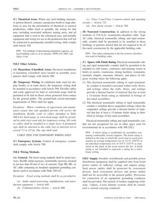
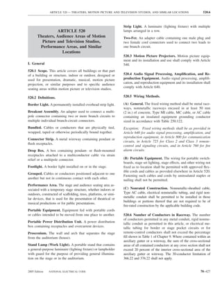
![520.45 ARTICLE 520 — THEATERS, MOTION PICTURE AND TELEVISION STUDIOS, AND SIMILAR LOCATIONS
(2) Cords and Cables Not in Contact with Heat- 520.45 Receptacles. Receptacles for electrical equipment on
Producing Equipment. Listed multiconductor extra-hard- stages shall be rated in amperes. Conductors supplying recep-
usage-type cords and cables not in direct contact with tacles shall be in accordance with Articles 310 and 400.
equipment containing heat-producing elements shall be per-
mitted to have their ampacity determined by Table 520.44. 520.46 Connector Strips, Drop Boxes, Floor Pockets,
Maximum load current in any conductor with an ampacity and Other Outlet Enclosures. Receptacles for the connec-
determined by Table 520.44 shall not exceed the values in tion of portable stage-lighting equipment shall be pendant
Table 520.44. or mounted in suitable pockets or enclosures and shall com-
ply with 520.45. Supply cables for connector strips and
drop boxes shall be as specified in 520.44(B).
Table 520.44 Ampacity of Listed Extra-Hard-Usage Cords
and Cables with Temperature Ratings of 75°C (167°F) and 520.47 Backstage Lamps (Bare Bulbs). Lamps (bare
90°C (194°F)* [Based on Ambient Temperature of 30°C
bulbs) installed in backstage and ancillary areas where they
(86°F)]
can come in contact with scenery shall be located and
guarded so as to be free from physical damage and shall
Temperature Rating of Cords
and Cables Maximum provide an air space of not less than 50 mm (2 in.) between
Rating of such lamps and any combustible material.
Size 75°C 90°C Overcurrent
(AWG) (167°F) (194°F) Device Exception: Decorative lamps installed in scenery shall not
be considered to be backstage lamps for the purpose of this
14 24 28 15 section.
12 32 35 20
10 41 47 25
8 57 65 35
520.48 Curtain Machines. Curtain machines shall be
listed.
6 77 87 45
4 101 114 60 520.49 Smoke Ventilator Control. Where stage smoke
2 133 152 80
ventilators are released by an electrical device, the circuit
* Ampacity shown is the ampacity for multiconductor cords and operating the device shall be normally closed and shall be
cables where only three copper conductors are current-carrying as controlled by at least two externally operable switches, one
described in 400.5. If the number of current-carrying conductors in a switch being placed at a readily accessible location on stage
cord or cable exceeds three and the load diversity factor is a minimum
of 50 percent, the ampacity of each conductor shall be reduced as and the other where designated by the authority having
shown in the following table. jurisdiction. The device shall be designed for the full volt-
age of the circuit to which it is connected, no resistance
being inserted. The device shall be located in the loft above
Number Percent
of of
the scenery and shall be enclosed in a suitable metal box
Conductors Ampacity having a tight, self-closing door.
4–6 80
7–24 70 IV. Portable Switchboards on Stage
25–42 60
43 and above 50 520.50 Road Show Connection Panel (A Type of Patch
Panel). A panel designed to allow for road show connec-
Note: Ultimate insulation temperature. In no case shall conductors be tion of portable stage switchboards to fixed lighting outlets
associated together in such a way with respect to the kind of circuit, by means of permanently installed supplementary circuits.
the wiring method used, or the number of conductors such that the The panel, supplementary circuits, and outlets shall comply
temperature limit of the conductors is exceeded.
A neutral conductor that carries only the unbalanced current from
with 520.50(A) through (D).
other conductors of the same circuit need not be considered as a
current-carrying conductor. (A) Load Circuits. Circuits shall terminate in grounding-
In a 3-wire circuit consisting of two phase wires and the neutral of type polarized inlets of current and voltage rating that
a 4-wire, 3-phase, wye-connected system, a common conductor car- match the fixed-load receptacle.
ries approximately the same current as the line-to-neutral currents of
the other conductors and shall be considered to be a current-carrying (B) Circuit Transfer. Circuits that are transferred between
conductor.
fixed and portable switchboards shall have all circuit con-
On a 4-wire, 3-phase, wye circuit where the major portion of the
load consists of nonlinear loads such as electric-discharge lighting, ductors transferred simultaneously.
electronic computer/data processing, or similar equipment, there are
harmonic currents present in the neutral conductor, and the neutral (C) Overcurrent Protection. The supply devices of these
shall be considered to be a current-carrying conductor. supplementary circuits shall be protected by branch-circuit
70–430 NATIONAL ELECTRICAL CODE 2005 Edition](https://image.slidesharecdn.com/nechandbookversin2005compacta-100921141249-phpapp02/85/Nec-handbook-version-2005-compacta-433-320.jpg)
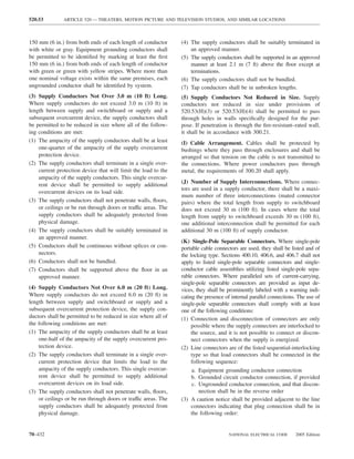

![550.11 ARTICLE 550 — MOBILE HOMES, MANUFACTURED HOMES, AND MOBILE HOME PARKS
(G) Protected. Where the cord passes through walls or nector or bar for the purposes of grounding, with sufficient
floors, it shall be protected by means of conduits and bushings terminals for all grounding conductors. The neutral bar termi-
or equivalent. The cord shall be permitted to be installed nation of the grounded circuit conductors shall be insulated in
within the mobile home walls, provided a continuous raceway accordance with 550.16(A). The disconnecting equipment
having a maximum size of 32 mm (11⁄4 in.) is installed from shall have a rating not less than the calculated load. The dis-
the branch-circuit panelboard to the underside of the mobile tribution equipment, either circuit breaker or fused type, shall
home floor. be located a minimum of 600 mm (24 in.) from the bottom of
such equipment to the floor level of the mobile home.
(H) Protection Against Corrosion and Mechanical Dam- FPN: See 550.20(B) for information on disconnecting
age. Permanent provisions shall be made for the protection means for branch circuits designed to energize heating or
of the attachment plug cap of the power-supply cord and air-conditioning equipment, or both, located outside the
any connector cord assembly or receptacle against corro- mobile home, other than room air conditioners.
sion and mechanical damage if such devices are in an ex- A distribution panelboard shall be rated not less than
terior location while the mobile home is in transit. 50 amperes and employ a 2-pole circuit breaker rated
(I) Mast Weatherhead or Raceway. Where the calculated 40 amperes for a 40-ampere supply cord, or 50 amperes
load exceeds 50 amperes or where a permanent feeder is used, for a 50-ampere supply cord. A distribution panelboard
the supply shall be by means of either of the following: employing a disconnect switch and fuses shall be rated
60 amperes and shall employ a single 2-pole, 60-ampere
(1) One mast weatherhead installation, installed in accor-
fuseholder with 40- or 50-ampere main fuses for 40- or
dance with Article 230, containing four continuous, in-
50-ampere supply cords, respectively. The outside of the
sulated, color-coded feeder conductors, one of which
distribution panelboard shall be plainly marked with the
shall be an equipment grounding conductor fuse size.
(2) A metal raceway or rigid nonmetallic conduit from the The distribution panelboard shall be located in an ac-
disconnecting means in the mobile home to the under- cessible location but shall not be located in a bathroom or a
side of the mobile home, with provisions for the attach- clothes closet. A clear working space at least 750 mm
ment to a suitable junction box or fitting to the raceway (30 in.) wide and 750 mm (30 in.) in front of the distribu-
on the underside of the mobile home [with or without tion panelboard shall be provided. This space shall extend
conductors as in 550.10(I)(1)]. The manufacturer shall from the floor to the top of the distribution panelboard.
provide written installation instructions stating the
proper feeder conductor sizes for the raceway and the (B) Branch-Circuit Protective Equipment. Branch-
size of the junction box to be used. circuit distribution equipment shall be installed in each mo-
bile home and shall include overcurrent protection for each
550.11 Disconnecting Means and Branch-Circuit Pro- branch circuit consisting of either circuit breakers or fuses.
tective Equipment. The branch-circuit equipment shall be The branch-circuit overcurrent devices shall be rated as
permitted to be combined with the disconnecting means as follows:
a single assembly. Such a combination shall be permitted to (1) Not more than the circuit conductors; and
be designated as a distribution panelboard. If a fused dis- (2) Not more than 150 percent of the rating of a single
tribution panelboard is used, the maximum fuse size for the appliance rated 13.3 amperes or more that is supplied
mains shall be plainly marked with lettering at least 6 mm by an individual branch circuit; but
(1⁄4 in.) high and visible when fuses are changed. (3) Not more than the overcurrent protection size and of
Where plug fuses and fuseholders are used, they shall the type marked on the air conditioner or other motor-
be tamper-resistant Type S, enclosed in dead-front fuse operated appliance.
panelboards. Electrical distribution panelboards containing
(C) Two-Pole Circuit Breakers. Where circuit breakers
circuit breakers shall also be dead-front type.
are provided for branch-circuit protection, 240-volt circuits
FPN: See 110.22 concerning identification of each discon- shall be protected by a 2-pole common or companion trip,
necting means and each service, feeder, or branch circuit at or handle-tied paired circuit breakers.
the point where it originated and the type marking needed.
(D) Electrical Nameplates. A metal nameplate on the out-
(A) Disconnecting Means. A single disconnecting means side adjacent to the feeder assembly entrance shall read:
shall be provided in each mobile home consisting of a circuit
THIS CONNECTION FOR 120/240-VOLT,
breaker, or a switch and fuses and its accessories installed in a
3-POLE, 4-WIRE, 60-HERTZ,
readily accessible location near the point of entrance of the
_____ AMPERE SUPPLY
supply cord or conductors into the mobile home. The main
circuit breakers or fuses shall be plainly marked “Main.” This The correct ampere rating shall be marked in the blank
equipment shall contain a solderless type of grounding con- space.
70–448 NATIONAL ELECTRICAL CODE 2005 Edition](https://image.slidesharecdn.com/nechandbookversin2005compacta-100921141249-phpapp02/85/Nec-handbook-version-2005-compacta-451-320.jpg)
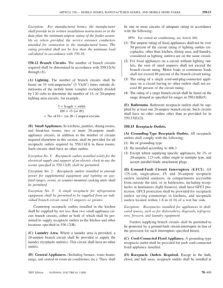
![550.14 ARTICLE 550 — MOBILE HOMES, MANUFACTURED HOMES, AND MOBILE HOME PARKS
wall spaces 600 mm (2 ft) wide or more so that no point along (G) Receptacle Outlets Not Required. Receptacle outlets
the floor line is more than 1.8 m (6 ft) measured horizontally shall not be required in the following locations:
from an outlet in that space. In addition, a receptacle outlet (1) In the wall space occupied by built-in kitchen or ward-
shall be installed in the following locations: robe cabinets
(1) Over or adjacent to countertops in the kitchen [at least (2) In the wall space behind doors that can be opened fully
one on each side of the sink if countertops are on each against a wall surface
side and are 300 mm (12 in.) or over in width]. (3) In room dividers of the lattice type that are less than
(2) Adjacent to the refrigerator and freestanding gas-range 2.5 m (8 ft) long, not solid, and within 150 mm
space. A duplex receptacle shall be permitted to serve (6 in.) of the floor
as the outlet for a countertop and a refrigerator. (4) In the wall space afforded by bar-type counters
(3) At countertop spaces for built-in vanities.
(4) At countertop spaces under wall-mounted cabinets. 550.14 Luminaires (Fixtures) and Appliances.
(5) In the wall at the nearest point to where a bar-type (A) Fasten Appliances in Transit. Means shall be pro-
counter attaches to the wall. vided to securely fasten appliances when the mobile home
(6) In the wall at the nearest point to where a fixed room is in transit. (See 550.16 for provisions on grounding.)
divider attaches to the wall.
(7) In laundry areas within 1.8 m (6 ft) of the intended (B) Accessibility. Every appliance shall be accessible for
location of the laundry appliance(s). inspection, service, repair, or replacement without removal
of permanent construction.
(8) At least one receptacle outlet located outdoors and ac-
cessible at grade level and not more than 2.0 m (61⁄2 ft) (C) Pendants. Listed pendant-type luminaires (fixtures) or
above grade. A receptacle outlet located in a compart- pendant cords shall be permitted.
ment accessible from the outside of the unit shall be
considered an outdoor receptacle. (D) Bathtub and Shower Luminaires (Fixtures). Where
(9) At least one receptacle outlet shall be installed in bath- a luminaire (lighting fixture) is installed over a bathtub or
rooms within 900 mm (36 in.) of the outside edge of in a shower stall, it shall be of the enclosed and gasketed
each basin. The receptacle outlet shall be located above type listed for wet locations.
or adjacent to the basin location. This receptacle shall
be in addition to any receptacle that is a part of a 550.15 Wiring Methods and Materials. Except as specifi-
luminaire (fixture) or appliance. The receptacle shall cally limited in this section, the wiring methods and materials
not be enclosed within a bathroom cabinet or vanity. included in this Code shall be used in mobile homes. Alumi-
num conductors, aluminum alloy conductors, and aluminum
(E) Pipe Heating Cable(s) Outlet. For the connection of core conductors such as copper-clad aluminum shall not be
pipe heating cable(s), a receptacle outlet shall be located on acceptable for use as branch-circuit wiring.
the underside of the unit as follows:
(A) Nonmetallic Boxes. Nonmetallic boxes shall be permit-
(1) Within 600 mm (2 ft) of the cold water inlet.
ted only with nonmetallic cable or nonmetallic raceways.
(2) Connected to an interior branch circuit, other than a
small appliance branch circuit. It shall be permitted to (B) Nonmetallic Cable Protection. Nonmetallic cable lo-
use a bathroom receptacle circuit for this purpose. cated 380 mm (15 in.) or less above the floor, if exposed,
(3) On a circuit where all of the outlets are on the load side shall be protected from physical damage by covering
of the ground-fault circuit-interrupter. boards, guard strips, or raceways. Cable likely to be dam-
(4) This outlet shall not be considered as the receptacle aged by stowage shall be so protected in all cases.
required by 550.13(D)(8). (C) Metal-Covered and Nonmetallic Cable Protection.
Metal-covered and nonmetallic cables shall be permitted to
(F) Receptacle Outlets Not Permitted. Receptacle outlets
pass through the centers of the wide side of 2 by 4 studs.
shall not be permitted in the following locations:
However, they shall be protected where they pass through
(1) Receptacle outlets shall not be installed within a bath- 2 by 2 studs or at other studs or frames where the cable or
tub or shower space. armor would be less than 32 mm (11⁄4 in.) from the inside
(2) A receptacle shall not be installed in a face-up position or outside surface of the studs where the wall covering
in any countertop. materials are in contact with the studs. Steel plates on each
(3) Receptacle outlets shall not be installed above electric side of the cable, or a tube, with not less than 1.35 mm
baseboard heaters, unless provided for in the listing or (0.053 in.) wall thickness shall be required to protect the
manufacturer’s instructions. cable. These plates or tubes shall be securely held in place.
70–450 NATIONAL ELECTRICAL CODE 2005 Edition](https://image.slidesharecdn.com/nechandbookversin2005compacta-100921141249-phpapp02/85/Nec-handbook-version-2005-compacta-453-320.jpg)
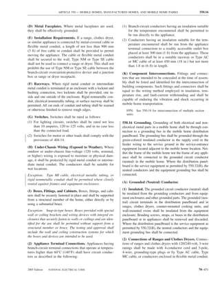
![550.17 ARTICLE 550 — MOBILE HOMES, MANUFACTURED HOMES, AND MOBILE HOME PARKS
(B) Equipment Grounding Means. 550.17 Testing.
(1) Supply Cord or Permanent Feeder. The green-colored (A) Dielectric Strength Test. The wiring of each mobile
insulated grounding wire in the supply cord or permanent home shall be subjected to a 1-minute, 900-volt, dielectric
feeder wiring shall be connected to the grounding bus in the strength test (with all switches closed) between live parts
distribution panelboard or disconnecting means. (including neutral) and the mobile home ground. Alterna-
tively, the test shall be permitted to be performed at 1080
(2) Electrical System. In the electrical system, all exposed volts for 1 second. This test shall be performed after branch
metal parts, enclosures, frames, lamp fixture canopies, and circuits are complete and after luminaires (fixtures) or ap-
so forth shall be effectively bonded to the grounding termi- pliances are installed.
nal or enclosure of the distribution panelboard.
Exception: Listed luminaires (fixtures) or appliances shall
(3) Cord-Connected Appliances. Cord-connected appli- not be required to withstand the dielectric strength test.
ances, such as washing machines, clothes dryers, and re-
frigerators, and the electrical system of gas ranges and so (B) Continuity and Operational Tests and Polarity
forth, shall be grounded by means of a cord with grounding Checks. Each mobile home shall be subjected to all of the
conductor and grounding-type attachment plug. following:
(1) An electrical continuity test to ensure that all exposed
(C) Bonding of Non–Current-Carrying Metal Parts. electrically conductive parts are properly bonded
(2) An electrical operational test to demonstrate that all
(1) Exposed Non–Current-Carrying Metal Parts. All
equipment, except water heaters and electric furnaces,
exposed non–current-carrying metal parts that may become
is connected and in working order
energized shall be effectively bonded to the grounding ter-
minal or enclosure of the distribution panelboard. A bond- (3) Electrical polarity checks of permanently wired equip-
ing conductor shall be connected between the distribution ment and receptacle outlets to determine that connec-
panelboard and accessible terminal on the chassis. tions have been properly made
(2) Grounding Terminals. Grounding terminals shall be 550.18 Calculations. The following method shall be em-
of the solderless type and listed as pressure-terminal con- ployed in calculating the supply-cord and distribution-
nectors recognized for the wire size used. The bonding panelboard load for each feeder assembly for each mo-
conductor shall be solid or stranded, insulated or bare, and bile home in lieu of the procedure shown in Article 220
shall be 8 AWG copper minimum, or equivalent. The bond- and shall be based on a 3-wire, 120/240-volt supply with
ing conductor shall be routed so as not to be exposed to 120-volt loads balanced between the two legs of the
physical damage. 3-wire system.
(3) Metallic Piping and Ducts. Metallic gas, water, and (A) Lighting, Small Appliance, and Laundry Load.
waste pipes and metallic air-circulating ducts shall be con- (1) Lighting Volt-Amperes. Length times width of mobile
sidered bonded if they are connected to the terminal on the home floor (outside dimensions) times 33 volt-amperes/m2
chassis [see 550.16(C)(1)] by clamps, solderless connec- (3 VA/ft2), for example, length × width × 3 = lighting volt-
tors, or by suitable grounding-type straps. amperes.
(4) Metallic Roof and Exterior Coverings. Any metallic (2) Small Appliance Volt-Amperes. Number of circuits
roof and exterior covering shall be considered bonded if the times 1500 volt-amperes for each 20-ampere appliance re-
following conditions are met: ceptacle circuit (see definition of Appliance, Portable, with
(1) The metal panels overlap one another and are securely note in 550.2), for example, number of circuits × 1500 =
attached to the wood or metal frame parts by metallic small appliance volt-amperes.
fasteners.
(3) Laundry Area Circuit Volt-Amperes. 1500 volt-
(2) The lower panel of the metallic exterior covering is
amperes.
secured by metallic fasteners at a cross member of the
chassis by two metal straps per mobile home unit or (4) Total Volt-Amperes. Lighting volt-amperes plus small
section at opposite ends. appliance volt-amperes plus laundry area volt-amperes
equals total volt-amperes.
The bonding strap material shall be a minimum of
100 mm (4 in.) in width of material equivalent to the skin (5) Net Volt-Amperes. First 3000 total volt-amperes at
or a material of equal or better electrical conductivity. The 100 percent plus remainder at 35 percent equals volt-
straps shall be fastened with paint-penetrating fittings such amperes to be divided by 240 volts to obtain current (am-
as screws and starwashers or equivalent. peres) per leg.
70–452 NATIONAL ELECTRICAL CODE 2005 Edition](https://image.slidesharecdn.com/nechandbookversin2005compacta-100921141249-phpapp02/85/Nec-handbook-version-2005-compacta-455-320.jpg)
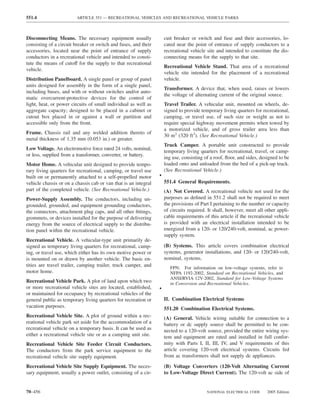
![551.31 ARTICLE 551 — RECREATIONAL VEHICLES AND RECREATIONAL VEHICLE PARKS
551.31 Multiple Supply Source. ner in which they have been tested and found suitable for
the intended use.
(A) Multiple Supply Sources. Where a multiple supply
system consisting of an alternate power source and a (C) Ground-Fault Circuit-Interrupter Protection. The
power-supply cord is installed, the feeder from the alternate internal wiring of a recreational vehicle having only one
power source shall be protected by an overcurrent- 15- or 20-ampere branch circuit as permitted in 551.42(A)
protective device. Installation shall be in accordance with and 551.42(B) shall have ground-fault circuit-interrupter
551.30(A), 551.30(B), and 551.40. protection for personnel. The ground-fault circuit inter-
• rupter shall be installed at the point where the power supply
(B) Multiple Supply Sources Capacity. The multiple sup- assembly terminates within the recreational vehicle. Where
ply sources shall not be required to be of the same capacity. a separable cord set is not employed, the ground-fault cir-
cuit interrupter shall be permitted to be an integral part of
(C) Alternate Power Sources Exceeding 30 Amperes. If
the attachment plug of the power supply assembly. The
an alternate power source exceeds 30 amperes, 120 volts,
ground-fault circuit interrupter shall provide protection also
nominal, it shall be permissible to wire it as a 120-volt,
under the conditions of an open grounded circuit conductor,
nominal, system or a 120/240-volt, nominal, system, pro-
interchanged circuit conductors, or both.
vided an overcurrent-protective device of the proper rating
is installed in the feeder. 551.41 Receptacle Outlets Required.
(D) Power-Supply Assembly Not Less Than 30 Am- (A) Spacing. Receptacle outlets shall be installed at wall
peres. The external power-supply assembly shall be permitted spaces 600 mm (2 ft) wide or more so that no point along
to be less than the calculated load but not less than 30 amperes the floor line is more than 1.8 m (6 ft), measured horizon-
and shall have overcurrent protection not greater than the ca- tally, from an outlet in that space.
pacity of the external power-supply assembly.
Exception No. 1: Bath and hall areas.
551.32 Other Sources. Other sources of ac power, such as Exception No. 2: Wall spaces occupied by kitchen cabi-
inverters, motor generators, or engine generators, shall be nets, wardrobe cabinets, built-in furniture, behind doors
listed for use in recreational vehicles and shall be installed that may open fully against a wall surface, or similar
in accordance with the terms of the listing. Other sources of facilities.
ac power shall be wired in full conformity with the require-
(B) Location. Receptacle outlets shall be installed as
ments in Parts I, II, III, IV, and V of this article covering
follows:
120-volt electrical systems.
(1) Adjacent to countertops in the kitchen [at least one on
551.33 Alternate Source Restriction. Transfer equipment, if each side of the sink if countertops are on each side and
not integral with the listed power source, shall be installed to are 300 mm (12 in.) or over in width]
ensure that the current-carrying conductors from other sources (2) Adjacent to the refrigerator and gas range space, ex-
of ac power and from an outside source are not connected to cept where a gas-fired refrigerator or cooking appli-
the vehicle circuit at the same time. ance, requiring no external electrical connection, is
factory installed
(3) Adjacent to countertop spaces of 300 mm (12 in.) or more
IV. Nominal 120-Volt or 120/240-Volt Systems
in width that cannot be reached from a receptacle required
551.40 120-Volt or 120/240-Volt, Nominal, Systems. in 551.41(B)(1) by a cord of 1.8 m (6 ft) without crossing
a traffic area, cooking appliance, or sink
(A) General Requirements. The electrical equipment and
material of recreational vehicles indicated for connection to (C) Ground-Fault Circuit-Interrupter Protection. Where
a wiring system rated 120 volts, nominal, 2-wire with provided, each 125-volt, single-phase, 15- or 20-ampere re-
ground, or a wiring system rated 120/240 volts, nominal, ceptacle outlet shall have ground-fault circuit-interrupter pro-
3-wire with ground, shall be listed and installed in accor- tection for personnel in the following locations:
dance with the requirements of Parts I, II, III, IV, and V of (1) Adjacent to a bathroom lavatory
this article. Electrical equipment connected line-to-line (2) Where the receptacles are installed to serve the coun-
shall have a voltage rating of 208–230 volts. tertop surfaces and are within 1.8 m (6 ft) of any lava-
tory or sink
(B) Materials and Equipment. Electrical materials, de-
vices, appliances, fittings, and other equipment installed in, Exception No. 1: Receptacles installed for appliances in
intended for use in, or attached to the recreational vehicle dedicated spaces, such as for dishwashers, disposals, re-
shall be listed. All products shall be used only in the man- frigerators, freezers, and laundry equipment.
70–458 NATIONAL ELECTRICAL CODE 2005 Edition](https://image.slidesharecdn.com/nechandbookversin2005compacta-100921141249-phpapp02/85/Nec-handbook-version-2005-compacta-461-320.jpg)
![ARTICLE 551 — RECREATIONAL VEHICLES AND RECREATIONAL VEHICLE PARKS 551.47
FPN: Complete details of this configuration can be found Exception No. 2: A recreational vehicle shall be permitted
in ANSI/NEMA WD 6-1989, National Electrical Manufac- to have the electrical point of entrance located more than
turers Association’s Standard for Dimensions of Attachment 4.5 m (15 ft) from the rear. Where this occurs, the distance
Plugs and Receptacles, Figure 5.20.
beyond the 4.5-m (15-ft) dimension shall be added to the
(3) Units with Two to Five 15- or 20-Ampere Branch cord’s minimum length as specified in 551.46(B).
Circuits. Recreational vehicles wired in accordance with Exception No. 3: Recreational vehicles designed for trans-
551.42(C) shall have an attachment plug that shall be 2-pole, porting livestock shall be permitted to have the electrical
3-wire grounding type, rated 30 amperes, 125 volts, conform- point of entrance located on either side or the front.
ing to the configuration shown in Figure 551.46(C), intended
for use with units rated at 30 amperes, 125 volts. 551.47 Wiring Methods.
FPN: Complete details of this configuration can be found (A) Wiring Systems. Cables and raceways installed in ac-
in ANSI/NEMA WD 6-1989, National Electrical Manufac- cordance with Articles 320, 322, 330 through 340, 342
turers Association’s Standard for Dimensions of Attachment through 362, 386, and 388 shall be permitted in accordance
Plugs and Receptacles, Figure TT. with their applicable article, except as otherwise specified
in this article. An equipment grounding means shall be pro-
(4) Units with 50-Ampere Power Supply Assembly. Rec-
vided in accordance with 250.118.
reational vehicles having a power-supply assembly rated
50 amperes as permitted by 551.42(D) shall have a 3-pole, (B) Conduit and Tubing. Where rigid metal conduit or
4-wire grounding-type attachment plug rated 50 amperes, intermediate metal conduit is terminated at an enclosure
125/250 volts, conforming to the configuration shown in with a locknut and bushing connection, two locknuts shall
Figure 551.46(C) . be provided, one inside and one outside of the enclosure.
All cut ends of conduit and tubing shall be reamed or oth-
FPN: Complete details of this configuration can be found erwise finished to remove rough edges.
in ANSI/NEMA WD 6-1989, National Electrical Manufac-
turers Association’s Standard for Dimensions of Attachment (C) Nonmetallic Boxes. Nonmetallic boxes shall be ac-
Plugs and Receptacles, Figure 14.50.
ceptable only with nonmetallic-sheathed cable or nonmetal-
(D) Labeling at Electrical Entrance. Each recreational lic raceways.
vehicle shall have permanently affixed to the exterior skin, (D) Boxes. In walls and ceilings constructed of wood or
at or near the point of entrance of the power-supply cord(s), other combustible material, boxes and fittings shall be flush
a label 75 mm × 45 mm (3 in. × 13⁄4 in.) minimum size, with the finished surface or project therefrom.
made of etched, metal-stamped, or embossed brass, stain-
less steel, or anodized or alclad aluminum not less than (E) Mounting. Wall and ceiling boxes shall be mounted in
0.51 mm (0.020 in.) thick, or other suitable material [e.g., accordance with Article 314.
0.13 mm (0.005 in.) thick plastic laminate] that reads, as Exception No. 1: Snap-in-type boxes or boxes provided
appropriate, either with special wall or ceiling brackets that securely fasten
THIS CONNECTION IS FOR 110–125-VOLT AC, boxes in walls or ceilings shall be permitted.
60 HZ, ____ AMPERE SUPPLY. Exception No. 2: A wooden plate providing a 38-mm (11⁄2-
or in.) minimum width backing around the box and of a thick-
THIS CONNECTION IS FOR 120/240-VOLT AC, ness of 13 mm (1⁄2 in.) or greater (actual) attached directly
3-POLE, 4-WIRE, 60 HZ, ______ AMPERE SUPPLY. to the wall panel shall be considered as approved means
for mounting outlet boxes.
The correct ampere rating shall be marked in the blank
space. (F) Raceway and Cable Continuity. Raceways and cable
sheaths shall be continuous between boxes and other enclo-
(E) Location. The point of entrance of a power-supply as- sures.
sembly shall be located within 4.5 m (15 ft) of the rear, on the
left (road) side or at the rear, left of the longitudinal center of (G) Protected. Metal-clad, Type AC, or nonmetallic-
the vehicle, within 450 mm (18 in.) of the outside wall. sheathed cables and electrical nonmetallic tubing shall be
permitted to pass through the centers of the wide side of 2
Exception No. 1: A recreational vehicle equipped with by 4 wood studs. However, they shall be protected where
only a listed flexible drain system or a side-vent drain sys- they pass through 2 by 2 wood studs or at other wood studs
tem shall be permitted to have the electrical point of en- or frames where the cable or tubing would be less than
trance located on either side, provided the drain(s) for the 32 mm (11⁄4 in.) from the inside or outside surface. Steel
plumbing system is (are) located on the same side. plates on each side of the cable or tubing or a steel tube,
2005 Edition NATIONAL ELECTRICAL CODE 70–461](https://image.slidesharecdn.com/nechandbookversin2005compacta-100921141249-phpapp02/85/Nec-handbook-version-2005-compacta-464-320.jpg)
![551.55 ARTICLE 551 — RECREATIONAL VEHICLES AND RECREATIONAL VEHICLE PARKS
electric ranges and electric clothes dryers utilizing a equipment grounding conductor and grounding-type attach-
grounded (neutral) conductor, if cord-connected, shall be ment plug.
made with 4-conductor cord and 3-pole, 4-wire grounding-
type plug caps and receptacles. 551.56 Bonding of Non–Current-Carrying Metal Parts.
(A) Required Bonding. All exposed non–current-carrying
551.55 Interior Equipment Grounding.
metal parts that may become energized shall be effectively
(A) Exposed Metal Parts. In the electrical system, all ex- bonded to the grounding terminal or enclosure of the dis-
posed metal parts, enclosures, frames, luminaire (lighting tribution panelboard.
fixture) canopies, and so forth, shall be effectively bonded
to the grounding terminals or enclosure of the distribution (B) Bonding Chassis. A bonding conductor shall be con-
panelboard. nected between any distribution panelboard and an accessible
terminal on the chassis. Aluminum or copper-clad aluminum
(B) Equipment Grounding and Bonding Conductors. conductors shall not be used for bonding if such conductors or
Bare wires, insulated wire with an outer finish that is green their terminals are exposed to corrosive elements.
or green with one or more yellow stripes, shall be used for Exception: Any recreational vehicle that employs a unitized
equipment grounding or bonding conductors only. metal chassis-frame construction to which the distribution
(C) Grounding of Electrical Equipment. Grounding of panelboard is securely fastened with a bolt(s) and nut(s) or by
electrical equipment shall be accomplished by one or more welding or riveting shall be considered to be bonded.
of the following methods: (C) Bonding Conductor Requirements. Grounding ter-
(1) Connection of metal raceway, the sheath of Type MC minals shall be of the solderless type and listed as pressure
and Type MI cable where the sheath is identified for terminal connectors recognized for the wire size used. The
grounding, or the armor of Type AC cable to metal bonding conductor shall be solid or stranded, insulated or
enclosures. bare, and shall be 8 AWG copper minimum, or equal.
(2) A connection between the one or more equipment
grounding conductors and a metal enclosure by means (D) Metallic Roof and Exterior Bonding. The metal roof
of a grounding screw, which shall be used for no other and exterior covering shall be considered bonded where
purpose, or a listed grounding device. both of the following conditions apply:
(3) The equipment grounding conductor in nonmetallic- (1) The metal panels overlap one another and are securely
sheathed cable shall be permitted to be secured under a attached to the wood or metal frame parts by metal
screw threaded into the luminaire (fixture) canopy fasteners.
other than a mounting screw or cover screw, or at- (2) The lower panel of the metal exterior covering is se-
tached to a listed grounding means (plate) in a nonme- cured by metal fasteners at each cross member of the
tallic outlet box for luminaire (fixture) mounting. chassis, or the lower panel is bonded to the chassis by
[Grounding means shall also be permitted for luminaire a metal strap.
(fixture) attachment screws.]
(E) Gas, Water, and Waste Pipe Bonding. The gas, wa-
(D) Grounding Connection in Nonmetallic Box. A con- ter, and waste pipes shall be considered grounded if they
nection between the one or more grounding conductors are bonded to the chassis.
brought into a nonmetallic outlet box shall be so arranged
(F) Furnace and Metal Air Duct Bonding. Furnace and
that a connection can be made to any fitting or device in
metal circulating air ducts shall be bonded.
that box that requires grounding.
(E) Grounding Continuity. Where more than one equip- 551.57 Appliance Accessibility and Fastening. Every ap-
ment grounding or bonding conductor of a branch circuit pliance shall be accessible for inspection, service, repair,
enters a box, all such conductors shall be in good electrical and replacement without removal of permanent construc-
contact with each other, and the arrangement shall be such tion. Means shall be provided to securely fasten appliances
that the disconnection or removal of a receptacle, luminaire in place when the recreational vehicle is in transit.
(fixture), or other device fed from the box will not interfere
with or interrupt the grounding continuity. V. Factory Tests
(F) Cord-Connected Appliances. Cord-connected appli- 551.60 Factory Tests (Electrical). Each recreational ve-
ances, such as washing machines, clothes dryers, refrigera- hicle designed with a 120-volt or a 120/240-volt electrical
tors, and the electrical system of gas ranges, and so forth, system shall withstand the applied potential without electri-
shall be grounded by means of an approved cord with cal breakdown of a 1-minute, 900-volt dielectric strength
70–464 NATIONAL ELECTRICAL CODE 2005 Edition](https://image.slidesharecdn.com/nechandbookversin2005compacta-100921141249-phpapp02/85/Nec-handbook-version-2005-compacta-467-320.jpg)
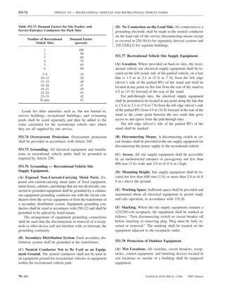
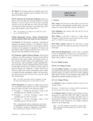
![ARTICLE 552 — PARK TRAILERS 552.41
Exception: External low-voltage supply shall be permitted ing both 120-volt and low-voltage connections shall be
to have the overcurrent protective device within 450 mm listed for dual voltage.
(18 in.) after entering the unit or after leaving a metal
raceway. (E) Autotransformers. Autotransformers shall not be used.
(F) Switches. Switches shall have a dc rating not less than (F) Receptacles and Plug Caps. Where a park trailer is
the connected load. equipped with a 120-volt or 120/240-volt ac system, a low-
(G) Luminaires (Lighting Fixtures). All low-voltage in- voltage system, or both, receptacles and plug caps of the low-
terior luminaires (lighting fixtures) rated more than 4 watts, voltage system shall differ in configuration from those of the
employing lamps rated more than 1.2 watts, shall be listed. 120-volt or 120/240-volt system. Where a unit equipped with
a battery or dc system has an external connection for low-
voltage power, the connector shall have a configuration that
III. Combination Electrical Systems will not accept 120-volt power.
552.20 Combination Electrical Systems.
(A) General. Unit wiring suitable for connection to a bat- IV. Nominal 120-Volt or 120/240-Volt Systems
tery or other low-voltage supply source shall be permitted
to be connected to a 120-volt source, provided that the 552.40 120-Volt or 120/240-Volt, Nominal, Systems.
entire wiring system and equipment are rated and installed (A) General Requirements. The electrical equipment and
in full conformity with Parts I, III, IV, and V requirements material of park trailers indicated for connection to a wiring
of this article covering 120-volt electrical systems. Circuits system rated 120 volts, nominal, 2-wire with ground, or a
fed from ac transformers shall not supply dc appliances.
wiring system rated 120/240 volts, nominal, 3-wire with
(B) Voltage Converters (120-Volt Alternating Current ground, shall be listed and installed in accordance with the
to Low-Voltage Direct Current). The 120-volt ac side of requirements of Parts I, III, IV, and V of this article.
the voltage converter shall be wired in full conformity
with Parts I, III, IV, and V requirements of this article for (B) Materials and Equipment. Electrical materials, de-
120-volt electrical systems. vices, appliances, fittings, and other equipment installed,
intended for use in, or attached to the park trailer shall be
Exception: Converters supplied as an integral part of a
listed. All products shall be used only in the manner in
listed appliance shall not be subject to 552.20(B).
which they have been tested and found suitable for the
All converters and transformers shall be listed for use in intended use.
recreation units and designed or equipped to provide over-
temperature protection. To determine the converter rating, 552.41 Receptacle Outlets Required.
the following formula shall be applied to the total con-
nected load, including average battery charging rate, of all (A) Spacing. Receptacle outlets shall be installed at wall
12-volt equipment: spaces 600 mm (2 ft) wide or more so that no point along
The first 20 amperes of load at 100 percent; plus the floor line is more than 1.8 m (6 ft), measured horizon-
The second 20 amperes of load at 50 percent; plus tally, from an outlet in that space.
All load above 40 amperes at 25 percent Exception No. 1: Bath and hall areas.
Exception: A low-voltage appliance that is controlled by a
Exception No. 2: Wall spaces occupied by kitchen cabi-
momentary switch (normally open) that has no means for
holding in the closed position shall not be considered as a nets, wardrobe cabinets, built-in furniture; behind doors
connected load when determining the required converter that may open fully against a wall surface; or similar
rating. Momentarily energized appliances shall be limited facilities.
to those used to prepare the unit for occupancy or travel.
(B) Location. Receptacle outlets shall be installed as
(C) Bonding Voltage Converter Enclosures. The non– follows:
current-carrying metal enclosure of the voltage converter (1) Adjacent to countertops in the kitchen [at least one on
shall be bonded to the frame of the unit with an 8 AWG each side of the sink if countertops are on each side and
copper conductor minimum. The grounding conductor for are 300 mm (12 in.) or over in width]
the battery and the metal enclosure shall be permitted to be
(2) Adjacent to the refrigerator and gas range space, except
the same conductor.
where a gas-fired refrigerator or cooking appliance, re-
(D) Dual-Voltage Fixtures Including Luminaires or Ap- quiring no external electrical connection, is factory-
pliances. Fixtures, including luminaires, or appliances hav- installed
2005 Edition NATIONAL ELECTRICAL CODE 70–469](https://image.slidesharecdn.com/nechandbookversin2005compacta-100921141249-phpapp02/85/Nec-handbook-version-2005-compacta-472-320.jpg)
![552.43 ARTICLE 552 — PARK TRAILERS
(3) Adjacent to countertop spaces of 300 mm (12 in.) or more 552.43 Power Supply.
in width that cannot be reached from a receptacle required (A) Feeder. The power supply to the park trailer shall be a
in 552.41(B)(1) by a cord of 1.8 m (6 ft) without crossing feeder assembly consisting of not more than one listed
a traffic area, cooking appliance, or sink 30-ampere or 50-ampere park trailer power-supply cord
with an integrally molded or securely attached cap, or a
(C) Ground-Fault Circuit-Interrupter Protection. Each
permanently installed feeder.
125-volt, single-phase, 15- or 20-ampere receptacle shall
have ground-fault circuit-interrupter protection for person- (B) Power-Supply Cord. If the park trailer has a power-
nel in the following locations: supply cord, it shall be permanently attached to the distri-
(1) Where the receptacles are installed to serve kitchen bution panelboard or to a junction box permanently con-
countertop surfaces nected to the distribution panelboard, with the free end
(2) Within 1.8 m (6 ft) of any lavatory or sink terminating in a molded-on attachment plug cap.
Cords with adapters and pigtail ends, extension cords,
Exception: Receptacles installed for appliances in dedi- and similar items shall not be attached to, or shipped with,
cated spaces, such as for dishwashers, disposals, refrigera- a park trailer.
tors, freezers, and laundry equipment. A suitable clamp or the equivalent shall be provided at
(3) In the area occupied by a toilet, shower, tub, or any the distribution panelboard knockout to afford strain relief
combination thereof for the cord to prevent strain from being transmitted to the
terminals when the power-supply cord is handled in its
(4) On the exterior of the unit
intended manner.
Exception: Receptacles that are located inside of an access The cord shall be a listed type with 3-wire, 120-volt or
panel that is installed on the exterior of the unit to supply 4-wire, 120/240-volt conductors, one of which shall be
power for an installed appliance shall not be required to identified by a continuous green color or a continuous
have ground-fault circuit-interrupter protection. green color with one or more yellow stripes for use as the
The receptacle outlet shall be permitted in a listed lu- grounding conductor.
minaire (lighting fixture). A receptacle outlet shall not be (C) Mast Weatherhead or Raceway. Where the calculated
installed in a tub or combination tub–shower compartment. load exceeds 50 amperes or where a permanent feeder is used,
the supply shall be by means of one of the following:
(D) Pipe Heating Cable Outlet. Where a pipe heating
(1) One mast weatherhead installation, installed in accor-
cable outlet is installed, the outlet shall be as follows:
dance with Article 230, containing four continuous, in-
(1) Located within 600 mm (2 ft) of the cold water inlet sulated, color-coded feeder conductors, one of which
(2) Connected to an interior branch circuit, other than a shall be an equipment grounding conductor
small appliance branch circuit (2) A metal raceway, rigid nonmetallic conduit, or liq-
(3) On a circuit where all of the outlets are on the load uidtight flexible nonmetallic conduit from the discon-
side of the ground-fault circuit-interrupter protection necting means in the park trailer to the underside of the
for personnel park trailer, with provisions for the attachment to a
(4) Mounted on the underside of the park trailer and shall suitable junction box or fitting to the raceway on the
not be considered to be the outdoor receptacle outlet underside of the park trailer [with or without conduc-
required in 552.41(E) tors as in 550.10(I)(1)]
(E) Outdoor Receptacle Outlets. At least one receptacle 552.44 Cord.
outlet shall be installed outdoors. A receptacle outlet lo- (A) Permanently Connected. Each power-supply assem-
cated in a compartment accessible from the outside of the bly shall be factory supplied or factory installed and con-
park trailer shall be considered an outdoor receptacle. Out- nected directly to the terminals of the distribution panel-
door receptacle outlets shall be protected as required in board or conductors within a junction box and provided
552.41(C)(4). with means to prevent strain from being transmitted to the
terminals. The ampacity of the conductors between each
(F) Receptacle Outlets Not Permitted. junction box and the terminals of each distribution panel-
(1) Shower or Bathtub Space. Receptacle outlets shall board shall be at least equal to the ampacity of the power-
not be installed in or within reach [750 mm (30 in.)] of a supply cord. The supply end of the assembly shall be
shower or bathtub space. equipped with an attachment plug of the type described in
552.44(C). Where the cord passes through the walls or
(2) Face-Up Position. A receptacle shall not be installed in floors, it shall be protected by means of conduit and bush-
a face-up position in any countertop. ings or equivalent. The cord assembly shall have permanent
70–470 NATIONAL ELECTRICAL CODE 2005 Edition](https://image.slidesharecdn.com/nechandbookversin2005compacta-100921141249-phpapp02/85/Nec-handbook-version-2005-compacta-473-320.jpg)
![ARTICLE 552 — PARK TRAILERS 552.45
provisions for protection against corrosion and mechanical (D) Labeling at Electrical Entrance. Each park trailer
damage while the unit is in transit. shall have permanently affixed to the exterior skin, at or
near the point of entrance of the power-supply assembly, a
(B) Cord Length. The cord-exposed usable length shall be
label 75 mm × 45 mm (3 in. × 13⁄4 in.) minimum size, made
measured from the point of entrance to the park trailer or
of etched, metal-stamped, or embossed brass, stainless
the face of the flanged surface inlet (motor-base attachment
steel, or anodized or alclad aluminum not less than
plug) to the face of the attachment plug at the supply end.
0.51 mm (0.020 in.) thick, or other suitable material [e.g.,
The cord-exposed usable length, measured to the point
of entry on the unit exterior, shall be a minimum of 7.0 m 0.13 mm (0.005 in.) thick plastic laminate], that reads, as
(23 ft) where the point of entrance is at the side of the unit, appropriate, either
or shall be a minimum 8.5 m (28 ft) where the point of THIS CONNECTION IS FOR 110–125-VOLT AC,
entrance is at the rear of the unit. The maximum length 60 HZ, 30 AMPERE SUPPLY
shall not exceed 11 m (361⁄2 ft).
Where the cord entrance into the unit is more than or
900 mm (3 ft) above the ground, the minimum cord lengths THIS CONNECTION IS FOR 120/240-VOLT AC,
above shall be increased by the vertical distance of the cord 3-POLE, 4-WIRE, 60 HZ, ______ AMPERE SUPPLY.
entrance heights above 900 mm (3 ft).
The correct ampere rating shall be marked in the blank
(C) Attachment Plugs. space.
(1) Units with Two to Five 15- or 20-Ampere Branch
(E) Location. The point of entrance of a power-supply
Circuits. Park trailers wired in accordance with 552.46(A)
shall have an attachment plug that shall be 2-pole, 3-wire assembly shall be located within 4.5 m (15 ft) of the rear,
grounding-type, rated 30 amperes, 125 volts, conforming to on the left (road) side or at the rear, left of the longitudinal
the configuration shown in Figure 552.44(C) intended for center of the unit, within 450 mm (18 in.) of the outside
use with units rated at 30 amperes, 125 volts. wall.
FPN: Complete details of this configuration can be found Exception: A park trailer shall be permitted to have the
in ANSI/NEMA WD 6-1989, National Electrical Manufac- electrical point of entrance located more than 4.5 m (15 ft)
turers Association’s Standard for Dimensions of Attachment from the rear. Where this occurs, the distance beyond the
Plugs and Receptacles, Figure TT.
4.5-m (15-ft) dimension shall be added to the cord’s mini-
(2) Units with 50-Ampere Power Supply Assembly. Park mum length as specified in 551.46(B).
trailers having a power-supply assembly rated 50 amperes as
permitted by 552.43(B) shall have a 3-pole, 4-wire grounding- 552.45 Distribution Panelboard.
type attachment plug rated 50 amperes, 125/250 volts, con-
(A) Listed and Appropriately Rated. A listed and appro-
forming to the configuration shown in Figure 552.44(C).
priately rated distribution panelboard shall be used. The
FPN: Complete details of this configuration can be found grounded conductor termination bar shall be insulated from
in ANSI/NEMA WD 6-1989, National Electrical Manufac- the enclosure as provided in 552.55(C). An equipment
turers Association Standard for Dimensions of Attachment
Plugs and Receptacles, Figure 14-50.
grounding terminal bar shall be attached inside the metal
enclosure of the panelboard.
(B) Location. The distribution panelboard shall be in-
Receptacles Caps stalled in a readily accessible location. Working clearance
for the panelboard shall be not less than 600 mm (24 in.)
G G
wide and 750 mm (30 in.) deep.
W W Exception: Where the panelboard cover is exposed to the
30-A,125-V, 2-pole, 3-wire, grounding type inside aisle space, one of the working clearance dimensions
shall be permitted to be reduced to a minimum of 550 mm
G G (22 in.). A panelboard shall be considered exposed where
Y X X Y the panelboard cover is within 50 mm (2 in.) of the aisle’s
W W finished surface.
50-A,125/250-V, 3-pole, 4-wire, grounding type
(C) Dead-Front Type. The distribution panelboard shall
Figure 552.44(C) Attachment Cap and Receptacle be of the dead-front type. A main disconnecting means shall
Configurations. be provided where fuses are used or where more than two
2005 Edition NATIONAL ELECTRICAL CODE 70–471](https://image.slidesharecdn.com/nechandbookversin2005compacta-100921141249-phpapp02/85/Nec-handbook-version-2005-compacta-474-320.jpg)
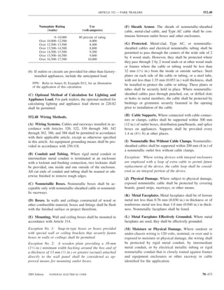
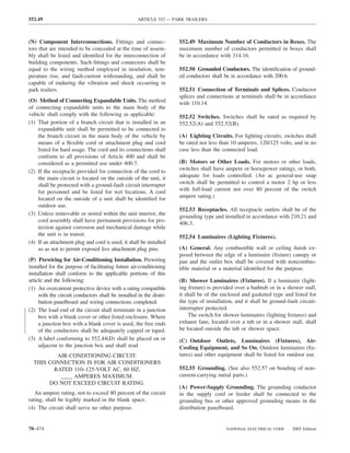
![ARTICLE 552 — PARK TRAILERS 552.57
(B) Distribution Panelboard. The distribution panelboard (E) Grounding Continuity. Where more than one equip-
shall have a grounding bus with sufficient terminals for all ment grounding conductor of a branch circuit enters a box,
grounding conductors or other approved grounding means. all such conductors shall be in good electrical contact with
each other, and the arrangement shall be such that the dis-
(C) Insulated Neutral. The grounded circuit conductor connection or removal of a receptacle, fixture, including a
(neutral) shall be insulated from the equipment grounding luminaire, or other device fed from the box will not inter-
conductors and from equipment enclosures and other fere with or interrupt the grounding continuity.
grounded parts. The grounded (neutral) circuit terminals in
the distribution panelboard and in ranges, clothes dryers, (F) Cord-Connected Appliances. Cord-connected appli-
counter-mounted cooking units, and wall-mounted ovens ances, such as washing machines, clothes dryers, refrigera-
shall be insulated from the equipment enclosure. Bonding tors, and the electrical system of gas ranges, and so on,
screws, straps, or buses in the distribution panelboard or in shall be grounded by means of an approved cord with
appliances shall be removed and discarded. Connection of equipment grounding conductor and grounding-type attach-
electric ranges and electric clothes dryers utilizing a ment plug.
grounded (neutral) conductor, if cord-connected, shall be
made with 4-conductor cord and 3-pole, 4-wire, grounding- 552.57 Bonding of Non–Current-Carrying Metal Parts.
type plug caps and receptacles. (A) Required Bonding. All exposed non–current-carrying
metal parts that may become energized shall be effectively
552.56 Interior Equipment Grounding. bonded to the grounding terminal or enclosure of the dis-
(A) Exposed Metal Parts. In the electrical system, all ex- tribution panelboard.
posed metal parts, enclosures, frames, luminaire (lighting (B) Bonding Chassis. A bonding conductor shall be con-
fixture) canopies, and so forth, shall be effectively bonded nected between any distribution panelboard and an ac-
to the grounding terminals or enclosure of the distribution cessible terminal on the chassis. Aluminum or copper-
panelboard. clad aluminum conductors shall not be used for bonding
if such conductors or their terminals are exposed to cor-
(B) Equipment Grounding Conductors. Bare wires,
rosive elements.
green-colored wires, or green wires with a yellow stripe(s)
shall be used for equipment grounding conductors only. Exception: Any park trailer that employs a unitized metal
chassis-frame construction to which the distribution panel-
(C) Grounding of Electrical Equipment. Where ground- board is securely fastened with a bolt(s) and nut(s) or by
ing of electrical equipment is specified, it shall be permitted welding or riveting shall be considered to be bonded.
as follows:
(1) Connection of metal raceway (conduit or electrical me- (C) Bonding Conductor Requirements. Grounding ter-
tallic tubing), the sheath of Type MC and Type MI minals shall be of the solderless type and listed as pressure
cable where the sheath is identified for grounding, or terminal connectors recognized for the wire size used. The
the armor of Type AC cable to metal enclosures. bonding conductor shall be solid or stranded, insulated or
bare, and shall be 8 AWG copper minimum or equivalent.
(2) A connection between the one or more equipment
grounding conductors and a metal box by means of a (D) Metallic Roof and Exterior Bonding. The metal roof
grounding screw, which shall be used for no other pur- and exterior covering shall be considered bonded where
pose, or a listed grounding device. both of the following conditions apply:
(3) The equipment grounding conductor in nonmetallic- (1) The metal panels overlap one another and are securely
sheathed cable shall be permitted to be secured under a attached to the wood or metal frame parts by metal
screw threaded into the luminaire (fixture) canopy fasteners.
other than a mounting screw or cover screw or attached
(2) The lower panel of the metal exterior covering is se-
to a listed grounding means (plate) in a nonmetallic
cured by metal fasteners at each cross member of the
outlet box for luminaire (fixture) mounting [grounding
chassis, or the lower panel is bonded to the chassis by
means shall also be permitted for luminaire (fixture)
a metal strap.
attachment screws].
(E) Gas, Water, and Waste Pipe Bonding. The gas, wa-
(D) Grounding Connection in Nonmetallic Box. A con- ter, and waste pipes shall be considered grounded if they
nection between the one or more grounding conductors are bonded to the chassis.
brought into a nonmetallic outlet box shall be arranged so
that a connection can be made to any fitting or device in (F) Furnace and Metal Air Duct Bonding. Furnace and
that box that requires grounding. metal circulating air ducts shall be bonded.
2005 Edition NATIONAL ELECTRICAL CODE 70–475](https://image.slidesharecdn.com/nechandbookversin2005compacta-100921141249-phpapp02/85/Nec-handbook-version-2005-compacta-478-320.jpg)

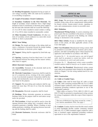
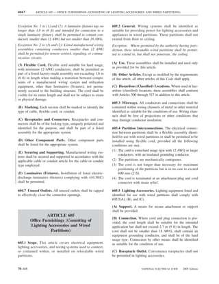
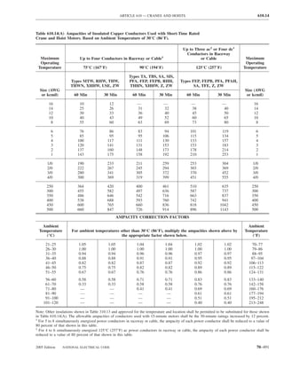
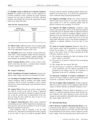
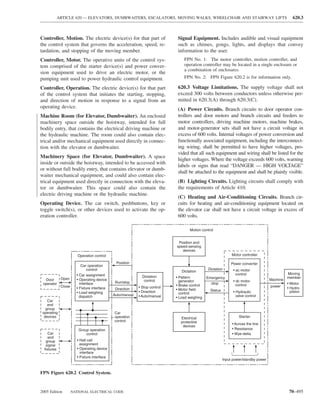
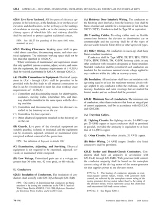
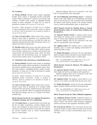
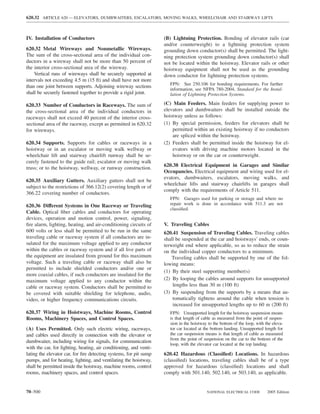
![ARTICLE 660 — X-RAY EQUIPMENT 660.20
FPN No. 2: In addition, information on radiation protec- The disconnecting means shall be operable from a location
tion by the National Council on Radiation Protection and readily accessible from the X-ray control. For equipment
Measurements is published as Reports of the National
connected to a 120-volt, nominal, branch circuit of 30 am-
Council on Radiation Protection and Measurement. These
reports can be obtained from NCRP Publications, 7910 peres or less, a grounding-type attachment plug cap and
Woodmont Ave., Suite 1016, Bethesda, MD 20814. receptacle of proper rating shall be permitted to serve as a
disconnecting means.
660.2 Definitions.
660.6 Rating of Supply Conductors and
Long-Time Rating. A rating based on an operating interval
Overcurrent Protection.
of 5 minutes or longer.
(A) Branch-Circuit Conductors. The ampacity of supply
Mobile. X-ray equipment mounted on a permanent base
branch-circuit conductors and the overcurrent protective de-
with wheels and/or casters for moving while completely
vices shall not be less than 50 percent of the momentary rating
assembled.
or 100 percent of the long-time rating, whichever is greater.
Momentary Rating. A rating based on an operating inter-
val that does not exceed 5 seconds. (B) Feeder Conductors. The rated ampacity of conductors
and overcurrent devices of a feeder for two or more branch
Portable. X-ray equipment designed to be hand-carried. circuits supplying X-ray units shall not be less than 100 per-
Transportable. X-ray equipment that is to be installed in a cent of the momentary demand rating [as determined by
vehicle or that may be readily disassembled for transport in 660.6(A)] of the two largest X-ray apparatus plus 20 percent
a vehicle. of the momentary ratings of other X-ray apparatus.
FPN: The minimum conductor size for branch and feeder
660.3 Hazardous (Classified) Locations. Unless approved circuits is also governed by voltage regulation requirements.
for the location, X-ray and related equipment shall not be For a specific installation, the manufacturer usually specifies
installed or operated in hazardous (classified) locations. minimum distribution transformer and conductor sizes, rating
of disconnect means, and overcurrent protection.
FPN: See Article 517, Part IV.
660.7 Wiring Terminals. X-ray equipment not provided
660.4 Connection to Supply Circuit. with a permanently attached cord or cord set shall be pro-
(A) Fixed and Stationary Equipment. Fixed and stationary vided with suitable wiring terminals or leads for the con-
X-ray equipment shall be connected to the power supply by nection of power-supply conductors of the size required by
means of a wiring method meeting the general require- the rating of the branch circuit for the equipment.
ments of this Code. Equipment properly supplied by a
branch circuit rated at not over 30 amperes shall be permit- 660.8 Number of Conductors in Raceway. The number
ted to be supplied through a suitable attachment plug cap of control circuit conductors installed in a raceway shall be
and hard-service cable or cord. determined in accordance with 300.17.
(B) Portable, Mobile, and Transportable Equipment. 660.9 Minimum Size of Conductors. Size 18 AWG or
Individual branch circuits shall not be required for portable, 16 AWG fixture wires, as specified in 725.27, and flexible
mobile, and transportable X-ray equipment requiring a ca- cords shall be permitted for the control and operating cir-
pacity of not over 60 amperes. Portable and mobile types of cuits of X-ray and auxiliary equipment where protected by
X-ray equipment of any capacity shall be supplied through not larger than 20-ampere overcurrent devices.
a suitable hard-service cable or cord. Transportable X-ray
equipment of any capacity shall be permitted to be con- 660.10 Equipment Installations. All equipment for new
nected to its power supply by suitable connections and X-ray installations and all used or reconditioned X-ray
hard-service cable or cord. equipment moved to and reinstalled at a new location shall
be of an approved type.
(C) Over 600 Volts, Nominal. Circuits and equipment op-
erated at more than 600 volts, nominal, shall comply with
Article 490. II. Control
660.20 Fixed and Stationary Equipment.
660.5 Disconnecting Means. A disconnecting means of
adequate capacity for at least 50 percent of the input re- (A) Separate Control Device. A separate control device,
quired for the momentary rating or 100 percent of the input in addition to the disconnecting means, shall be incorpo-
required for the long-time rating of the X-ray equipment, rated in the X-ray control supply or in the primary circuit to
whichever is greater, shall be provided in the supply circuit. the high-voltage transformer. This device shall be a part of
2005 Edition NATIONAL ELECTRICAL CODE 70–519](https://image.slidesharecdn.com/nechandbookversin2005compacta-100921141249-phpapp02/85/Nec-handbook-version-2005-compacta-522-320.jpg)
![ARTICLE 670 — INDUSTRIAL MACHINERY 670.3
669.3 General. Equipment for use in electroplating pro- FPN: For information on the workspace requirements for
cesses shall be identified for such service. equipment containing supply conductor terminals, see 110.26.
For information on the workspace requirements for machine
power and control equipment, see NFPA 79–2002, Electrical
669.5 Branch-Circuit Conductors. Branch-circuit conduc-
Standard for Industrial Machinery.
tors supplying one or more units of equipment shall have an
ampacity of not less than 125 percent of the total connected 670.2 Definitions.
load. The ampacities for busbars shall be in accordance Industrial Machinery (Machine). A power-driven ma-
with 366.10. chine (or a group of machines working together in a coor-
dinated manner), not portable by hand while working, that
669.6 Wiring Methods. Conductors connecting the elec-
is used to process material by cutting; forming; pressure;
trolyte tank equipment to the conversion equipment shall be electrical, thermal, or optical techniques; lamination; or a
in accordance with 669.6(A) and 669.6(B). combination of these processes. It can include associated
(A) Systems Not Exceeding 50 Volts Direct Current. In- equipment used to transfer material or tooling, including
sulated conductors shall be permitted to be run without fixtures, to assemble/disassemble, to inspect or test, or to
insulated support, provided they are protected from physi- package. [The associated electrical equipment, including
cal damage. Bare copper or aluminum conductors shall be the logic controller(s) and associated software or logic to-
permitted where supported on insulators. gether with the machine actuators and sensors, are consid-
ered as part of the industrial machine.]
(B) Systems Exceeding 50 Volts Direct Current. Insulated Industrial Manufacturing System. A systematic array of
conductors shall be permitted to be run on insulated sup- one or more industrial machines that is not portable by
ports, provided they are protected from physical damage. hand and includes any associated material handling, ma-
Bare copper or aluminum conductors shall be permitted nipulating, gauging, measuring, or inspection equipment.
where supported on insulators and guarded against acciden-
tal contact up to the point of termination in accordance with 670.3 Machine Nameplate Data.
110.27. (A) Permanent Nameplate. A permanent nameplate shall
be attached to the control equipment enclosure or machine
669.7 Warning Signs. Warning signs shall be posted to and shall be plainly visible after installation. The nameplate
indicate the presence of bare conductors. shall include the following information:
669.8 Disconnecting Means. (1) Supply voltage, phase, frequency, and full-load current
(2) Maximum ampere rating of the short-circuit and ground-
(A) More Than One Power Supply. Where more than one
fault protective device
power supply serves the same dc system, a disconnecting
means shall be provided on the dc side of each power supply. (3) Ampere rating of largest motor, from the motor name-
plate, or load
(B) Removable Links or Conductors. Removable links (4) Short circuit current rating of the machine industrial
or removable conductors shall be permitted to be used as control panel based on one of the following:
the disconnecting means. a. Short circuit current rating of a listed and labeled
669.9 Overcurrent Protection. Direct-current conductors machine control enclosure or assembly
b. Short circuit current rating established utilizing an
shall be protected from overcurrent by one or more of the
approved method
following:
(1) Fuses or circuit breakers FPN: UL 508A-2001, Supplement SB, is an example of an
approved method.
(2) A current-sensing device that operates a disconnecting
means (5) Electrical diagram number(s) or the number of the in-
dex to the electrical drawings
(3) Other approved means
The full-load current shown on the nameplate shall not be
less than the sum of the full-load currents required for all
motors and other equipment that may be in operation at the
same time under normal conditions of use. Where unusual
ARTICLE 670
type loads, duty cycles, and so forth require oversized conduc-
Industrial Machinery tors or permit reduced-size conductors, the required capacity
shall be included in the marked “full-load current.” Where
670.1 Scope. This article covers the definition of, the more than one incoming supply circuit is to be provided, the
nameplate data for, and the size and overcurrent protection nameplate shall state the preceding information for each circuit.
of supply conductors to industrial machinery. FPN: See 430.22(E) and 430.26 for duty cycle requirements.
2005 Edition NATIONAL ELECTRICAL CODE 70–525](https://image.slidesharecdn.com/nechandbookversin2005compacta-100921141249-phpapp02/85/Nec-handbook-version-2005-compacta-528-320.jpg)
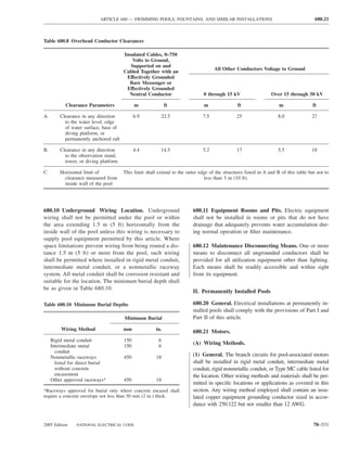
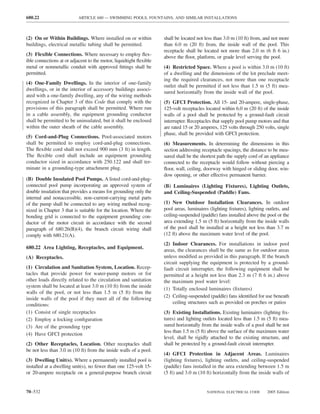
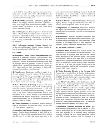
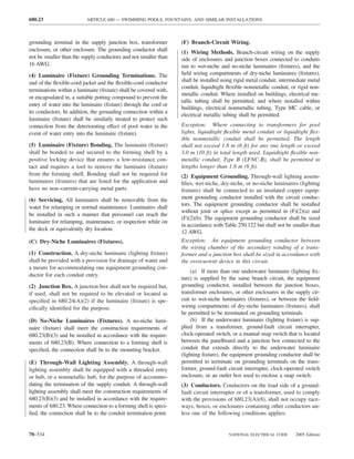
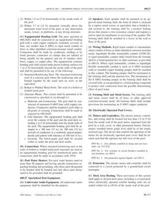
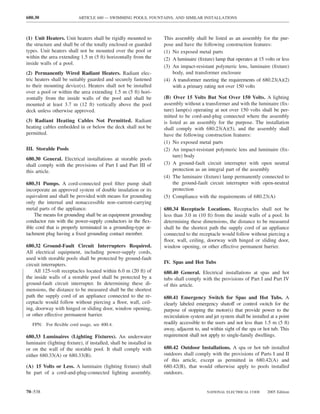
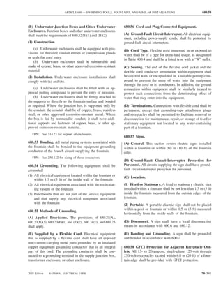
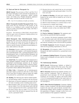
![ARTICLE 690 — SOLAR PHOTOVOLTAIC SYSTEMS 690.1
of the qualified person(s) shall be kept in a permanent 685.14 Ungrounded Control Circuits. Where operational
record at the office of the establishment in charge of the continuity is required, control circuits of 150 volts or less
completed installation. from separately derived systems shall be permitted to be
A person designated as a qualified person shall pos- ungrounded.
sess the skills and knowledge related to the construc-
tion and operation of the electrical equipment and in-
stallation and shall have received documented safety
training on the hazards involved. Documentation of ARTICLE 690
their qualifications shall be on file with the office of the Solar Photovoltaic Systems
establishment in charge of the completed installation.
(3) Effective safeguards acceptable to the authority having
jurisdiction are established and maintained. I. General
690.1 Scope. The provisions of this article apply to solar
685.3 Application of Other Articles. The articles/sections photovoltaic electrical energy systems, including the array
in Table 685.3 apply to particular cases of installation of circuit(s), inverter(s), and controller(s) for such systems.
conductors and equipment, where there are orderly shut- [See Figure 690.1(A) and Figure 690.1(B).] Solar photovol-
down requirements that are in addition to those of this taic systems covered by this article may be interactive with
article or are modifications of them. other electrical power production sources or stand-alone,
with or without electrical energy storage such as batteries.
These systems may have ac or dc output for utilization.
Table 685.3 Application of Other Articles
Conductor/Equipment Section Photovoltaic source circuits
More than one building or other 225, Part II Photovoltaic
Blocking diodes output circuit
structure
Ground-fault protection of 230.95, Exception No. 1
equipment Fuses
Protection of conductors 240.4
Electrical system coordination 240.12
Ground-fault protection of 240.13(1) Solar cells
equipment
Grounding ac systems of 50 volts 250.21
to 1000 volts
Equipment protection 427.22 Module
Orderly shutdown 430.44
Disconnection 430.74, Exception Nos. 1 Panel
and 2
Disconnecting means in sight 430.102(A), Exception No. 2
from controller
Energy from more than one 430.113, Exception Nos. 1 Array or photovoltaic
source and 2 power source
Disconnecting means 645.10, Exception
Uninterruptible power supplies 645.11(1)
(UPS) Dedicated branch circuit
Point of connection 705.12(A) of the electric production
and distribution network
Inverter output
II. Orderly Shutdown ac module (includes inverter)
Array (of ac modules)
685.10 Location of Overcurrent Devices in or on Pre- ac module system
mises. Location of overcurrent devices that are critical to Notes:
integrated electrical systems shall be permitted to be acces- 1. These diagrams are intended to be a means of identification for
photovoltaic system components, circuits, and connections.
sible, with mounting heights permitted to ensure security 2. Disconnecting means required by Article 690, Part III, are not shown.
from operation by unqualified personnel. 3. System grounding and equipment grounding are not shown.
See Article 690, Part V.
685.12 Direct-Current System Grounding. Two-wire dc Figure 690.1(A) Identification of Solar Photovoltaic
circuits shall be permitted to be ungrounded. System Components.
2005 Edition NATIONAL ELECTRICAL CODE 70–545](https://image.slidesharecdn.com/nechandbookversin2005compacta-100921141249-phpapp02/85/Nec-handbook-version-2005-compacta-548-320.jpg)
![690.2 ARTICLE 690 — SOLAR PHOTOVOLTAIC SYSTEMS
Photovoltaic source circuits into the outer surface or structure of a building and serve as
Inverter input circuit
the outer protective surface of that building.
Inverter output
Electric production Charge Controller. Equipment that controls dc voltage or
and distribution dc current, or both, used to charge a battery.
Photovoltaic output circuit network connection
Inverter Diversion Charge Controller. Equipment that regulates
Interactive system
the charging process of a battery by diverting power from
Wind, engine-generator, energy storage to direct-current or alternating-current loads
micro-hydro-electric, and Energy storage, charge controller,
other power sources and system control or to an interconnected utility service.
Inverter input circuit Electrical Production and Distribution Network. A power
Inverter output production, distribution, and utilization system, such as a
Photovoltaic utility system and connected loads, that is external to and
output circuit not controlled by the photovoltaic power system.
dc loads Inverter
Hybrid system Hybrid System. A system comprised of multiple power
sources. These power sources may include photovoltaic,
Charge controller
wind, micro-hydro generators, engine-driven generators,
Inverter input circuit and others, but do not include electrical production and
Photovoltaic output
circuit Inverter output distribution network systems. Energy storage systems, such
Main supply as batteries, do not constitute a power source for the pur-
equipment for
Inverter ac loads pose of this definition.
Main supply equipment Interactive System. A solar photovoltaic system that oper-
for dc loads
ates in parallel with and may deliver power to an electrical
Stand-alone system Energy storage
production and distribution network. For the purpose of this
Notes: definition, an energy storage subsystem of a solar photovol-
1. These diagrams are intended to be a means of identification for
photovoltaic system components, circuits, and connections. taic system, such as a battery, is not another electrical pro-
2. Disconnecting means and overcurrent protection required by duction source.
Article 690 are not shown.
3. System grounding and equipment grounding are not shown. Inverter. Equipment that is used to change voltage level or
See Article 690, Part V.
4. Custom designs occur in each configuration, and some components waveform, or both, of electrical energy. Commonly, an in-
are optional. verter [also known as a power conditioning unit (PCU) or
power conversion system (PCS)] is a device that changes dc
Figure 690.1(B) Identification of Solar Photovoltaic System
Components in Common System Configurations. input to an ac output. Inverters may also function as battery
chargers that use alternating current from another source and
convert it into direct current for charging batteries.
690.2 Definitions.
Inverter Input Circuit. Conductors between the inverter
Alternating-Current (ac) Module (Alternating-Current and the battery in stand-alone systems or the conductors
Photovoltaic Module). A complete, environmentally pro- between the inverter and the photovoltaic output circuits for
tected unit consisting of solar cells, optics, inverter, and electrical production and distribution network.
other components, exclusive of tracker, designed to gener- Inverter Output Circuit. Conductors between the inverter
ate ac power when exposed to sunlight. and an ac panelboard for stand-alone systems or the con-
Array. A mechanically integrated assembly of modules or ductors between the inverter and the service equipment or
panels with a support structure and foundation, tracker, and another electric power production source, such as a utility,
other components, as required, to form a direct-current for electrical production and distribution network.
power-producing unit. Module. A complete, environmentally protected unit con-
sisting of solar cells, optics, and other components, exclu-
Bipolar Photovoltaic Array. A photovoltaic array that has
sive of tracker, designed to generate dc power when ex-
two outputs, each having opposite polarity to a common
posed to sunlight.
reference point or center tap.
Panel. A collection of modules mechanically fastened to-
Blocking Diode. A diode used to block reverse flow of gether, wired, and designed to provide a field-installable unit.
current into a photovoltaic source circuit.
Photovoltaic Output Circuit. Circuit conductors between
Building Integrated Photovoltaics. Photovoltaic cells, de- the photovoltaic source circuit(s) and the inverter or dc
vices, modules, or modular materials that are integrated utilization equipment.
70–546 NATIONAL ELECTRICAL CODE 2005 Edition](https://image.slidesharecdn.com/nechandbookversin2005compacta-100921141249-phpapp02/85/Nec-handbook-version-2005-compacta-549-320.jpg)
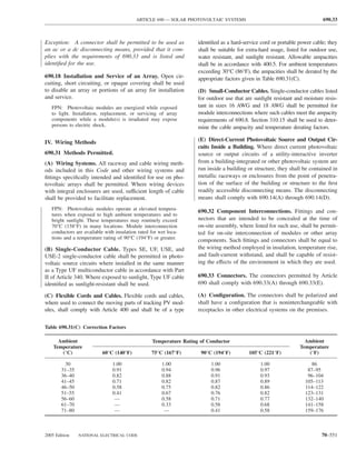
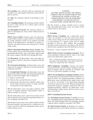
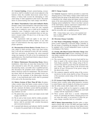
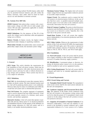
![ARTICLE 695 — FIRE PUMPS 695.3
VIII. Outputs Over 600 Volts 695.3 Power Source(s) for Electric Motor-Driven Fire
Pumps. Electric motor-driven fire pumps shall have a reli-
692.80 General. Fuel cell systems with a maximum output able source of power.
voltage over 600 volts ac shall comply with the require-
ments of other articles applicable to such installations. (A) Individual Sources. Where reliable, and where capable
of carrying indefinitely the sum of the locked-rotor current of
the fire pump motor(s) and the pressure maintenance pump
motor(s) and the full-load current of the associated fire pump
accessory equipment when connected to this power supply,
ARTICLE 695
the power source for an electric motor-driven fire pump shall
Fire Pumps be one or more of the following.
(1) Electric Utility Service Connection. A fire pump shall
FPN: Rules that are followed by a reference in brackets
be permitted to be supplied by a separate service, or from a
contain text that has been extracted from NFPA 20-2003,
Standard for the Installation of Stationary Pumps for Fire connection located ahead of and not within the same cabi-
Protection. Only editorial changes were made to the ex- net, enclosure, or vertical switchboard section as the service
tracted text to make it consistent with this Code. disconnecting means. The connection shall be located and
arranged so as to minimize the possibility of damage by fire
695.1 Scope. from within the premises and from exposing hazards. A tap
ahead of the service disconnecting means shall comply with
(A) Covered. This article covers the installation of the
230.82(5). The service equipment shall comply with the
following:
labeling requirements in 230.2 and the location require-
(1) Electric power sources and interconnecting circuits ments in 230.72(B). [NFPA 20:9.2.2]
(2) Switching and control equipment dedicated to fire (2) On-Site Power Production Facility. A fire pump
pump drivers shall be permitted to be supplied by an on-site power
production facility. The source facility shall be located
(B) Not Covered. This article does not cover the following:
and protected to minimize the possibility of damage by
(1) The performance, maintenance, and acceptance testing fire. [NFPA 20:9.2.3]
of the fire pump system, and the internal wiring of the
components of the system (B) Multiple Sources. Where reliable power cannot be ob-
tained from a source described in 695.3(A), power shall be
(2) Pressure maintenance (jockey or makeup) pumps
supplied from an approved combination of two or more of
FPN: See NFPA 20-2003, Standard for the Installation either of such sources, or from an approved combination of
of Stationary Pumps for Fire Protection, for further feeders constituting two or more power sources as covered
information. in 695.3(B)(2), or from an approved combination of one or
more of such power sources in combination with an on-site
695.2 Definitions. standby generator complying with 695.3(B)(1) and (B)(3).
Fault Tolerant External Control Circuits. Those control (1) Generator Capacity. An on-site generator(s) used to
circuits either entering or leaving the fire pump controller comply with this section shall be of sufficient capacity to
enclosure, which if broken, disconnected, or shorted will allow normal starting and running of the motor(s) driving
not prevent the controller from starting the fire pump from the fire pump(s) while supplying all other simultaneously
all other internal or external means and may cause the con- operated load. Automatic shedding of one or more optional
troller to start the pump under these conditions. standby loads in order to comply with this capacity require-
ment shall be permitted. A tap ahead of the on-site genera-
On-Site Power Production Facility. The normal supply of tor disconnecting means shall not be required. The require-
electric power for the site that is expected to be constantly ments of 430.113 shall not apply. [NFPA 20:9.6.1]
producing power.
(2) Feeder Sources. This section applies to multibuilding
On-Site Standby Generator. A facility producing electric campus-style complexes with fire pumps at one or more
power on site as the alternate supply of electric power. It buildings. Where sources in 695.3(A) are not practicable,
differs from an on-site power production facility, in that it is and with the approval of the authority having jurisdiction,
not constantly producing power. two or more feeder sources shall be permitted as one power
2005 Edition NATIONAL ELECTRICAL CODE 70–559](https://image.slidesharecdn.com/nechandbookversin2005compacta-100921141249-phpapp02/85/Nec-handbook-version-2005-compacta-562-320.jpg)
![695.4 ARTICLE 695 — FIRE PUMPS
source or as more than one power source where such feed- (4) Be located sufficiently remote from other building or
ers are connected to or derived from separate utility ser- other fire pump source disconnecting means such that in-
vices. The connection(s), overcurrent protective device(s), advertent contemporaneous operation would be unlikely
and disconnecting means for such feeders shall meet the (3) Disconnect Marking. The disconnecting means shall
requirements of 695.4(B). [NFPA 20:9.2.5.3] be marked “Fire Pump Disconnecting Means.” The letters
(3) Arrangement. The power sources shall be arranged so shall be at least 25 mm (1 in.) in height, and they shall be
that a fire at one source will not cause an interruption at the visible without opening enclosure doors or covers.
other source. [NFPA 20:9.2.5.1] (4) Controller Marking. A placard shall be placed adja-
cent to the fire pump controller, stating the location of this
695.4 Continuity of Power. Circuits that supply electric disconnecting means and the location of the key (if the
motor-driven fire pumps shall be supervised from inadvert- disconnecting means is locked).
ent disconnection as covered in 695.4(A) or 695.4(B). (5) Supervision. The disconnecting means shall be super-
vised in the closed position by one of the following methods:
(A) Direct Connection. The supply conductors shall di-
(1) Central station, proprietary, or remote station signal
rectly connect the power source to either a listed fire pump
device
controller or listed combination fire pump controller and
power transfer switch. [NFPA 20:9.3.2.2.2] (2) Local signaling service that causes the sounding of an
audible signal at a constantly attended point
(B) Supervised Connection. A single disconnecting (3) Locking the disconnecting means in the closed position
means and associated overcurrent protective device(s) shall (4) Sealing of disconnecting means and approved weekly
be permitted to be installed between a remote power source recorded inspections when the disconnecting means are
and one of the following: located within fenced enclosures or in buildings under
(1) A listed fire pump controller the control of the owner [NFPA 20:9.3.2.2.3]
(2) A listed fire pump power transfer switch 695.5 Transformers. Where the service or system voltage
(3) A listed combination fire pump controller and power is different from the utilization voltage of the fire pump
transfer switch motor, transformer(s) protected by disconnecting means
For systems installed under the provisions of 695.3(B)(2) and overcurrent protective devices shall be permitted to be
only, such additional disconnecting means and associated installed between the system supply and the fire pump con-
overcurrent protective device(s) shall be permitted as re- troller in accordance with 695.5(A) and (B), or (C). Only
quired to comply with other provisions of this Code. Over- transformers covered in 695.5(C) shall be permitted to sup-
current protective devices between an on-site standby gen- ply loads not directly associated with the fire pump system.
erator and a fire pump controller shall be selected and sized (A) Size. Where a transformer supplies an electric motor-
according to 430.62 to provide short-circuit protection only. driven fire pump, it shall be rated at a minimum of 125 per-
All disconnecting devices and overcurrent protective de- cent of the sum of the fire pump motor(s) and pressure
vices that are unique to the fire pump loads shall comply maintenance pump(s) motor loads, and 100 percent of the
with 695.4(B)(1) through (B)(5). associated fire pump accessory equipment supplied by the
transformer.
(1) Overcurrent Device Selection. The overcurrent pro-
tective device(s) shall be selected or set to carry indefinitely (B) Overcurrent Protection. The primary overcurrent pro-
the sum of the locked-rotor current of the fire pump mo- tective device(s) shall be selected or set to carry indefinitely
tor(s) and the pressure maintenance pump motor(s) and the the sum of the locked-rotor current of the fire pump motor(s)
full-load current of the associated fire pump accessory and the pressure maintenance pump motor(s) and the full-load
equipment when connected to this power supply. The re- current of the associated fire pump accessory equipment when
quirement to carry the locked-rotor currents indefinitely connected to this power supply. Secondary overcurrent protec-
shall not apply to conductors or devices other than overcur- tion shall not be permitted. The requirement to carry the
rent devices in the fire pump motor circuit(s). locked-rotor currents indefinitely shall not apply to conductors
or devices other than overcurrent devices in the fire pump
(2) Disconnecting Means. The disconnecting means shall motor circuit(s).
comply with all of the following:
(C) Feeder Source. Where a feeder source is provided in
(1) Be identified as suitable for use as service equipment accordance with 695.3(B)(2), transformers supplying the
(2) Be lockable in the closed position fire pump system shall be permitted to supply other loads.
(3) Not be located within equipment that feeds loads other All other loads shall be calculated in accordance with Ar-
than the fire pump ticle 220, including demand factors as applicable.
70–560 NATIONAL ELECTRICAL CODE 2005 Edition](https://image.slidesharecdn.com/nechandbookversin2005compacta-100921141249-phpapp02/85/Nec-handbook-version-2005-compacta-563-320.jpg)
![695.7 ARTICLE 695 — FIRE PUMPS
other equipment, including a pressure maintenance (jockey) 695.14 Control Wiring.
pump(s). A fire pump controller and fire pump power trans-
fer switch, where provided, shall not serve any load other (A) Control Circuit Failures. External control circuits that
than the fire pump for which it is intended. extend outside the fire pump room shall be arranged so that
failure of any external circuit (open or short circuit) shall not
(G) Mechanical Protection. All wiring from engine con- prevent the operation of a pump(s) from all other internal or
trollers and batteries shall be protected against physical external means. Breakage, disconnecting, shorting of the
damage and shall be installed in accordance with the con- wires, or loss of power to these circuits could cause continu-
troller and engine manufacturer’s instructions. ous running of the fire pump but shall not prevent the control-
(H) Ground Fault Protection of Equipment. Ground fault ler(s) from starting the fire pump(s) due to causes other than
protection of equipment shall not be permitted for fire pumps. these external control circuits. All control conductors within
the fire pump room that are not fault tolerant shall be protected
695.7 Voltage Drop. The voltage at the controller line ter- against physical damage. [NFPA 20:10.5.2.6, 12.5.2.5]
minals shall not drop more than 15 percent below normal
(controller-rated voltage) under motor starting conditions. (B) Sensor Functioning. No undervoltage, phase-loss,
The voltage at the motor terminals shall not drop more than frequency-sensitive, or other sensor(s) shall be installed
5 percent below the voltage rating of the motor when the that automatically or manually prohibit actuation of the mo-
motor is operating at 115 percent of the full-load current tor contactor. [NFPA 20:10.4.5.6]
rating of the motor.
Exception: A phase loss sensor(s) shall be permitted only
Exception: This limitation shall not apply for emergency as a part of a listed fire pump controller.
run mechanical starting. [NFPA 20:9.4]
(C) Remote Device(s). No remote device(s) shall be in-
695.10 Listed Equipment. Diesel engine fire pump con- stalled that will prevent automatic operation of the transfer
trollers, electric fire pump controllers, electric motors, fire switch. [NFPA 20:10.8.1.3]
pump power transfer switches, foam pump controllers, and
limited service controllers shall be listed for fire pump ser- (D) Engine-Drive Control Wiring. All wiring between
vice. [NFPA 20:9.5.1.1, 10.1.2.1, 12.1.3.1] the controller and the diesel engine shall be stranded and
sized to continuously carry the charging or control currents
695.12 Equipment Location. as required by the controller manufacturer. Such wiring
(A) Controllers and Transfer Switches. Electric motor- shall be protected against physical damage. Controller
driven fire pump controllers and power transfer switches manufacturer’s specifications for distance and wire size
shall be located as close as practicable to, and within sight shall be followed. [NFPA 20:12.3.5.1]
of, the motors that they control.
(E) Electric Fire Pump Control Wiring Methods. All
(B) Engine-Drive Controllers. Engine-drive fire pump electric motor-driven fire pump control wiring shall be in
controllers shall be located as close as is practical to, and rigid metal conduit, intermediate metal conduit, liquidtight
within sight of, the engines that they control. flexible metal conduit, liquidtight flexible nonmetallic con-
(C) Storage Batteries. Storage batteries for fire pump en- duit Type B (LFNC-B), listed Type MC cable with an im-
gine drives shall be supported above the floor, secured pervious covering, or Type MI cable.
against displacement, and located where they are not sub-
(F) Generator Control Wiring Methods. Control con-
ject to physical damage, flooding with water, excessive
ductors installed between the fire pump power transfer
temperature, or excessive vibration.
switch and the standby generator supplying the fire pump
(D) Energized Equipment. All energized equipment parts during normal power loss shall be kept entirely independent
shall be located at least 300 mm (12 in.) above the floor level. of all other wiring. They shall be protected to resist poten-
tial damage by fire or structural failure. They shall be per-
(E) Protection Against Pump Water. Fire pump control-
mitted to be routed through a building(s) encased in 50 mm
lers and power transfer switches shall be located or pro-
(2 in.) of concrete or within enclosed construction dedi-
tected so that they are not damaged by water escaping from
cated to the fire pump circuits and having a minimum
pumps or pump connections.
1-hour fire resistance rating, or circuit protective systems
(F) Mounting. All fire pump control equipment shall be with a minimum of 1-hour fire resistance. The installation
mounted in a substantial manner on noncombustible sup- shall comply with any restrictions provided in the listing of
porting structures. the electrical circuit protective system used.
70–562 NATIONAL ELECTRICAL CODE 2005 Edition](https://image.slidesharecdn.com/nechandbookversin2005compacta-100921141249-phpapp02/85/Nec-handbook-version-2005-compacta-565-320.jpg)
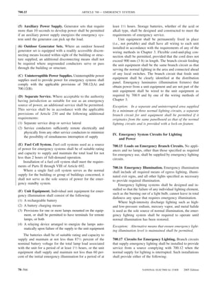
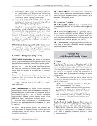
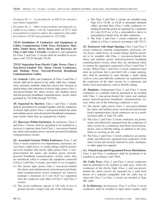
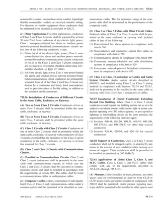
![ARTICLE 800 — COMMUNICATIONS CIRCUITS 800.18
Chapter 8 Communications Systems
transmission of audio, video, and data, and including power
ARTICLE 800 equipment (e.g., dc converters, inverters and batteries) and
Communications Circuits technical support equipment (e.g., computers).
Exposed. A circuit that is in such a position that, in case of
FPN: Rules that are followed by a reference in brackets failure of supports and insulation, contact with another cir-
contain text that has been extracted from NFPA 97–2003, cuit may result.
Standard Glossary of Terms Relating to Chimneys, Vents,
and Heat-Producing Appliances. Only editorial changes FPN: See Article 100 for two other definitions of Exposed.
were made to the extracted text to make it consistent with
this Code. Point of Entrance. Within a building, the point at which
the wire or cable emerges from an external wall, from a
concrete floor slab, or from a rigid metal conduit or an
I. General intermediate metal conduit grounded to an electrode in ac-
800.1 Scope. This article covers telephone, telegraph (except cordance with 800.100(B).
radio), outside wiring for fire alarm and burglar alarm, and
Premises. The land and buildings of a user located on the
similar central station systems; and telephone systems not con-
user side of the utility-user network point of demarcation.
nected to a central station system but using similar types of
equipment, methods of installation, and maintenance. Wire. A factory assembly of one or more insulated conduc-
FPN No. 1: For further information for fire alarm, sprinkler tors without an overall covering.
waterflow, and sprinkler supervisory systems, see Article 760.
FPN No. 2: For installation requirements of optical fiber 800.3 Other Articles.
cables, see Article 770.
(A) Hybrid Power and Communications Cables. The
FPN No. 3: For installation requirements for network- provisions of 780.6 shall apply for listed hybrid power and
powered broadband communications circuits, see Article 830.
communications cables in closed-loop and programmed
800.2 Definitions. See Article 100. For purposes of this power distribution.
article, the following additional definitions apply. FPN: See 800.179(J) for hybrid power and communica-
tions cable in other applications.
Abandoned Communications Cable. Installed communi-
cations cable that is not terminated at both ends at a con-
(B) Hazardous (Classified) Locations. Communications
nector or other equipment and not identified for future use
circuits and equipment installed in a location that is classi-
with a tag.
fied in accordance with Article 500 shall comply with the
Air Duct. A conduit or passageway for conveying air to or applicable requirements of Chapter 5.
from heating, cooling, air conditioning, or ventilating
equipment, but not including the plenum. [NFPA 97:1.2.6] (C) Spread of Fire or Products of Combustion. Section
300.21 shall apply. The accessible portion of abandoned
Block. A square or portion of a city, town, or village en- communications cables shall not be permitted to remain.
closed by streets and including the alleys so enclosed, but
not any street. (D) Equipment in Other Space Used for Environmental
Cable. A factory assembly of two or more conductors hav- Air. Section 300.22(C) shall apply.
ing an overall covering.
800.18 Installation of Equipment. Equipment electrically
Cable Sheath. A covering over the conductor assembly connected to a telecommunications network shall be listed
that may include one or more metallic members, strength in accordance with 800.170. Installation of equipment shall
members, or jackets. also comply with 110.3(B).
Communications Circuit Integrity (CI) Cable. Cable used •
Exception: This listing requirement shall not apply to test
in communications systems to ensure continued operation of
equipment that is intended for temporary connection to a
critical circuits during a specified time under fire conditions.
telecommunications network by qualified persons during
Communications Equipment. The electronic equipment the course of installation, maintenance, or repair of tele-
that performs the telecommunications operations for the communications equipment or systems.
2005 Edition NATIONAL ELECTRICAL CODE 70–597](https://image.slidesharecdn.com/nechandbookversin2005compacta-100921141249-phpapp02/85/Nec-handbook-version-2005-compacta-600-320.jpg)
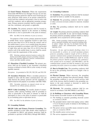
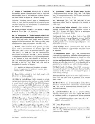
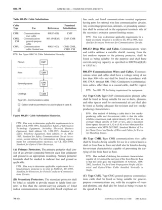
![ARTICLE 820 — COMMUNITY ANTENNA TELEVISION AND RADIO DISTRIBUTION SYSTEMS 820.3
810.56 Protection Against Accidental Contact. Lead-in (C) Interlocks on Doors. All access doors shall be provided
conductors to radio transmitters shall be located or installed with interlocks that disconnect all voltages of over 350 volts
so as to make accidental contact with them difficult. between conductors when any access door is opened.
810.57 Antenna Discharge Units — Transmitting Sta-
tions. Each conductor of a lead-in for outdoor antennas shall
be provided with an antenna discharge unit or other suitable
means that drain static charges from the antenna system. ARTICLE 820
Community Antenna Television and
Exception No. 1: Where protected by a continuous metal- Radio Distribution Systems
lic shield that is permanently and effectively grounded.
Exception No. 2: Where the antenna is permanently and
effectively grounded. FPN: Rules that are followed by a reference in brackets
contain text that has been extracted from NFPA 97-2003,
Standard Glossary of Terms Relating to Chimneys, Vents,
810.58 Grounding Conductors — Amateur Transmit- and Heat-Producing Appliances. Only editorial changes
ting and Receiving Stations. Grounding conductors shall were made to the extracted text to make it consistent with
comply with 810.58(A) through 810.58(C). this Code.
(A) Other Sections. All grounding conductors for amateur I. General
transmitting and receiving stations shall comply with
810.21(A) through 810.21(K). 820.1 Scope. This article covers coaxial cable distribution
of radio frequency signals typically employed in commu-
(B) Size of Protective Grounding Conductor. The pro- nity antenna television (CATV) systems.
tective grounding conductor for transmitting stations shall
be as large as the lead-in but not smaller than 10 AWG 820.2 Definitions. See Article 100. For the purposes of this
copper, bronze, or copper-clad steel. article, the following additional definitions apply.
(C) Size of Operating Grounding Conductor. The oper- Abandoned Coaxial Cable. Installed coaxial cable that is
ating grounding conductor for transmitting stations shall not terminated at equipment other than a coaxial connector
not be less than 14 AWG copper or its equivalent. and not identified for future use with a tag.
Air Duct. A conduit or passageway for conveying air to or
IV. Interior Installation — Transmitting Stations from heating, cooling, air conditioning, or ventilating
equipment, but not including the plenum. [NFPA 97:1.2.6]
810.70 Clearance from Other Conductors. All conduc-
tors inside the building shall be separated at least 100 mm Exposed. An exposed cable is one that is in such a position
(4 in.) from the conductors of any electric light, power, or that, in case of failure of supports and insulation, contact
signaling circuit. with another circuit could result.
Exception No. 1: As provided in Article 640. FPN: See Article 100 for two other definitions of exposed.
Exception No. 2: Where separated from other conductors Point of Entrance. The point within a building at which
by raceway or some firmly fixed nonconductor, such as the cable emerges from an external wall, from a concrete
porcelain tubes or flexible tubing. floor slab, or from a rigid metal conduit or an intermediate
metal conduit grounded to an electrode in accordance with
810.71 General. Transmitters shall comply with 810.71(A) 820.100(B).
through 810.71(C).
Premises. The land and buildings of a user located on the
(A) Enclosing. The transmitter shall be enclosed in a metal user side of utility-user network point of demarcation.
frame or grille, or separated from the operating space by a
barrier or other equivalent means, all metallic parts of 820.3 Other Articles. Circuits and equipment shall com-
which are effectively connected to ground. ply with 820.3(A) through 820.3(G).
(B) Grounding of Controls. All external metal handles (A) Spread of Fire or Products of Combustion. Sec-
and controls accessible to the operating personnel shall be tion 300.21 shall apply. The accessible portion of aban-
effectively grounded. doned coaxial cables shall be removed.
2005 Edition NATIONAL ELECTRICAL CODE 70–609](https://image.slidesharecdn.com/nechandbookversin2005compacta-100921141249-phpapp02/85/Nec-handbook-version-2005-compacta-612-320.jpg)
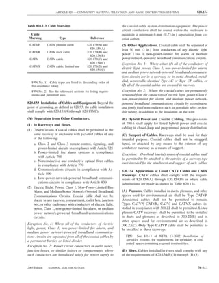
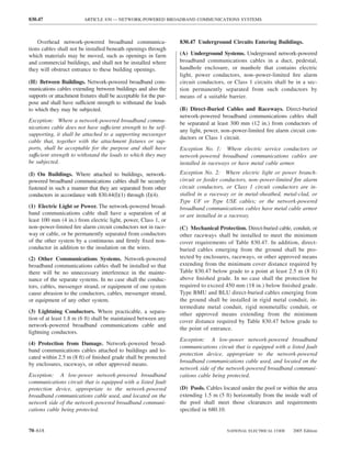
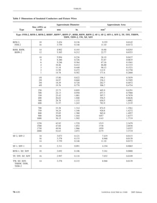
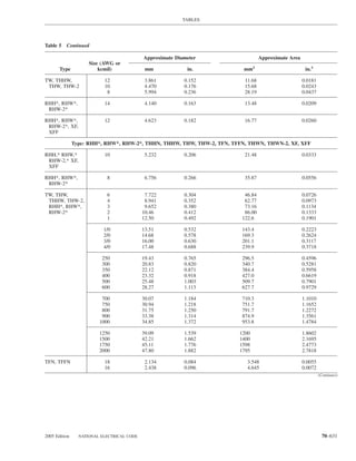
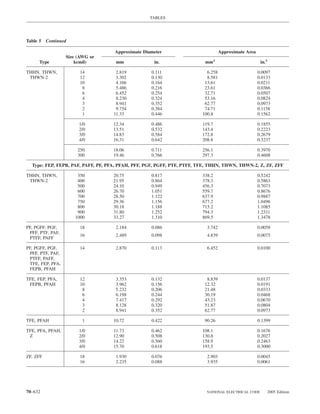
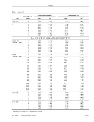
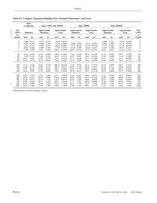
![TABLES
Table 8 Conductor Properties
Conductors Direct-Current Resistance at 75°C (167°F)
Stranding Overall Copper
Size Area Diameter Diameter Area Uncoated Coated Aluminum
(AWG
or Circular ohm/ ohm/ ohm/ ohm/ ohm/ ohm/
kcmil) mm2 mils Quantity mm in. mm in. mm2 in.2 km kFT km kFT km kFT
18 0.823 1620 1 — — 1.02 0.040 0.823 0.001 25.5 7.77 26.5 8.08 42.0 12.8
18 0.823 1620 7 0.39 0.015 1.16 0.046 1.06 0.002 26.1 7.95 27.7 8.45 42.8 13.1
16 1.31 2580 1 — — 1.29 0.051 1.31 0.002 16.0 4.89 16.7 5.08 26.4 8.05
16 1.31 2580 7 0.49 0.019 1.46 0.058 1.68 0.003 16.4 4.99 17.3 5.29 26.9 8.21
14 2.08 4110 1 — — 1.63 0.064 2.08 0.003 10.1 3.07 10.4 3.19 16.6 5.06
14 2.08 4110 7 0.62 0.024 1.85 0.073 2.68 0.004 10.3 3.14 10.7 3.26 16.9 5.17
12 3.31 6530 1 — — 2.05 0.081 3.31 0.005 6.34 1.93 6.57 2.01 10.45 3.18
12 3.31 6530 7 0.78 0.030 2.32 0.092 4.25 0.006 6.50 1.98 6.73 2.05 10.69 3.25
10 5.261 10380 1 — — 2.588 0.102 5.26 0.008 3.984 1.21 4.148 1.26 6.561 2.00
10 5.261 10380 7 0.98 0.038 2.95 0.116 6.76 0.011 4.070 1.24 4.226 1.29 6.679 2.04
8 8.367 16510 1 — — 3.264 0.128 8.37 0.013 2.506 0.764 2.579 0.786 4.125 1.26
8 8.367 16510 7 1.23 0.049 3.71 0.146 10.76 0.017 2.551 0.778 2.653 0.809 4.204 1.28
6 13.30 26240 7 1.56 0.061 4.67 0.184 17.09 0.027 1.608 0.491 1.671 0.510 2.652 0.808
4 21.15 41740 7 1.96 0.077 5.89 0.232 27.19 0.042 1.010 0.308 1.053 0.321 1.666 0.508
3 26.67 52620 7 2.20 0.087 6.60 0.260 34.28 0.053 0.802 0.245 0.833 0.254 1.320 0.403
2 33.62 66360 7 2.47 0.097 7.42 0.292 43.23 0.067 0.634 0.194 0.661 0.201 1.045 0.319
1 42.41 83690 19 1.69 0.066 8.43 0.332 55.80 0.087 0.505 0.154 0.524 0.160 0.829 0.253
1/0 53.49 105600 19 1.89 0.074 9.45 0.372 70.41 0.109 0.399 0.122 0.415 0.127 0.660 0.201
2/0 67.43 133100 19 2.13 0.084 10.62 0.418 88.74 0.137 0.3170 0.0967 0.329 0.101 0.523 0.159
3/0 85.01 167800 19 2.39 0.094 11.94 0.470 111.9 0.173 0.2512 0.0766 0.2610 0.0797 0.413 0.126
4/0 107.2 211600 19 2.68 0.106 13.41 0.528 141.1 0.219 0.1996 0.0608 0.2050 0.0626 0.328 0.100
250 127 — 37 2.09 0.082 14.61 0.575 168 0.260 0.1687 0.0515 0.1753 0.0535 0.2778 0.0847
300 152 — 37 2.29 0.090 16.00 0.630 201 0.312 0.1409 0.0429 0.1463 0.0446 0.2318 0.0707
350 177 — 37 2.47 0.097 17.30 0.681 235 0.364 0.1205 0.0367 0.1252 0.0382 0.1984 0.0605
400 203 — 37 2.64 0.104 18.49 0.728 268 0.416 0.1053 0.0321 0.1084 0.0331 0.1737 0.0529
500 253 — 37 2.95 0.116 20.65 0.813 336 0.519 0.0845 0.0258 0.0869 0.0265 0.1391 0.0424
600 304 — 61 2.52 0.099 22.68 0.893 404 0.626 0.0704 0.0214 0.0732 0.0223 0.1159 0.0353
700 355 — 61 2.72 0.107 24.49 0.964 471 0.730 0.0603 0.0184 0.0622 0.0189 0.0994 0.0303
750 380 — 61 2.82 0.111 25.35 0.998 505 0.782 0.0563 0.0171 0.0579 0.0176 0.0927 0.0282
800 405 — 61 2.91 0.114 26.16 1.030 538 0.834 0.0528 0.0161 0.0544 0.0166 0.0868 0.0265
900 456 — 61 3.09 0.122 27.79 1.094 606 0.940 0.0470 0.0143 0.0481 0.0147 0.0770 0.0235
1000 507 — 61 3.25 0.128 29.26 1.152 673 1.042 0.0423 0.0129 0.0434 0.0132 0.0695 0.0212
1250 633 — 91 2.98 0.117 32.74 1.289 842 1.305 0.0338 0.0103 0.0347 0.0106 0.0554 0.0169
1500 760 — 91 3.26 0.128 35.86 1.412 1011 1.566 0.02814 0.00858 0.02814 0.00883 0.0464 0.0141
1750 887 — 127 2.98 0.117 38.76 1.526 1180 1.829 0.02410 0.00735 0.02410 0.00756 0.0397 0.0121
20001013 — 127 3.19 0.126 41.45 1.632 1349 2.092 0.02109 0.00643 0.02109 0.00662 0.0348 0.0106
Notes:
1. These resistance values are valid only for the parameters as given. Using conductors having coated strands,
different stranding type, and, especially, other temperatures changes the resistance.
2. Formula for temperature change: R2 = R1 [1 + α (T2 − 75)] where αcu = 0.00323, αAL = 0.00330 at 75°C.
3. Conductors with compact and compressed stranding have about 9 percent and 3 percent, respectively, smaller
bare conductor diameters than those shown. See Table 5A for actual compact cable dimensions.
4. The IACS conductivities used: bare copper = 100%, aluminum = 61%.
5. Class B stranding is listed as well as solid for some sizes. Its overall diameter and area is that of its circumscribing circle.
FPN: The construction information is per NEMA WC8-
1992 or ANSI/UL 1581-1998. The resistance is calculated
per National Bureau of Standards Handbook 100, dated
1966, and Handbook 109, dated 1972.
2005 Edition NATIONAL ELECTRICAL CODE 70–635](https://image.slidesharecdn.com/nechandbookversin2005compacta-100921141249-phpapp02/85/Nec-handbook-version-2005-compacta-638-320.jpg)
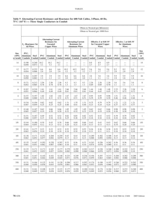
![TABLES
Table 9 Continued
Ohms to Neutral per Kilometer
Ohms to Neutral per 1000 Feet
Alternating-Current
Resistance for Alternating-Current Effective Z at 0.85 PF Effective Z at 0.85 PF
XL (Reactance) for Uncoated Resistance for for Uncoated Copper for Aluminum
All Wires Copper Wires Aluminum Wires Wires Wires
Size
Size PVC, (AWG
(AWG Aluminum Steel PVC Aluminum Steel PVC Aluminum Steel PVC Aluminum Steel PVC Aluminum Steel or
or kcmil) Conduits Conduit Conduit Conduit Conduit Conduit Conduit Conduit Conduit Conduit Conduit Conduit Conduit Conduit kcmil)
500 0.128 0.157 0.089 0.105 0.095 0.141 0.157 0.148 0.141 0.157 0.164 0.187 0.200 0.210 500
0.039 0.048 0.027 0.032 0.029 0.043 0.048 0.045 0.043 0.048 0.050 0.057 0.061 0.064
600 0.128 0.157 0.075 0.092 0.082 0.118 0.135 0.125 0.131 0.144 0.154 0.167 0.180 0.190 600
0.039 0.048 0.023 0.028 0.025 0.036 0.041 0.038 0.040 0.044 0.047 0.051 0.055 0.058
750 0.125 0.157 0.062 0.079 0.069 0.095 0.112 0.102 0.118 0.131 0.141 0.148 0.161 0.171 750
0.038 0.048 0.019 0.024 0.021 0.029 0.034 0.031 0.036 0.040 0.043 0.045 0.049 0.052
1000 0.121 0.151 0.049 0.062 0.059 0.075 0.089 0.082 0.105 0.118 0.131 0.128 0.138 0.151 1000
0.037 0.046 0.015 0.019 0.018 0.023 0.027 0.025 0.032 0.036 0.040 0.039 0.042 0.046
Notes:
1. These values are based on the following constants: UL-Type RHH wires with Class B stranding, in cradled
configuration. Wire conductivities are 100 percent IACS copper and 61 percent IACS aluminum, and
aluminum conduit is 45 percent IACS. Capacitive reactance is ignored, since it is negligible at these
voltages. These resistance values are valid only at 75°C (167°F) and for the parameters as given, but are
representative for 600-volt wire types operating at 60 Hz.
2. Effective Z is defined as R cos(θ) + X sin(θ), where θ is the power factor angle of the circuit. Multiplying
current by effective impedance gives a good approximation for line-to-neutral voltage drop. Effective im-
pedance values shown in this table are valid only at 0.85 power factor. For another circuit power factor (PF),
effective impedance (Ze) can be calculated from R and XL values given in this table as follows: Ze = R × PF
+ XL sin[arccos(PF)].
Tables 11(A) and 11(B)
For listing purposes, Table 11(A) and Table 11(B) provide class of supply and its electrical rating. A Class 2 power
the required power source limitations for Class 2 and Class 3 source not suitable for wet location use shall be so marked.
power sources. Table 11(A) applies for alternating-current
sources, and Table 11(B) applies for direct-current sources. Exception: Limited power circuits used by listed informa-
The power for Class 2 and Class 3 circuits shall be either tion technology equipment.
(1) inherently limited, requiring no overcurrent protection, or Overcurrent devices, where required, shall be located at
(2) not inherently limited, requiring a combination of power the point where the conductor to be protected receives its
source and overcurrent protection. Power sources designed for supply and shall not be interchangeable with devices of
interconnection shall be listed for the purpose. higher ratings. The overcurrent device shall be permitted as
As part of the listing, the Class 2 or Class 3 power source an integral part of the power source.
shall be durably marked where plainly visible to indicate the
2005 Edition NATIONAL ELECTRICAL CODE 70–637](https://image.slidesharecdn.com/nechandbookversin2005compacta-100921141249-phpapp02/85/Nec-handbook-version-2005-compacta-640-320.jpg)
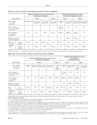
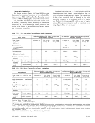
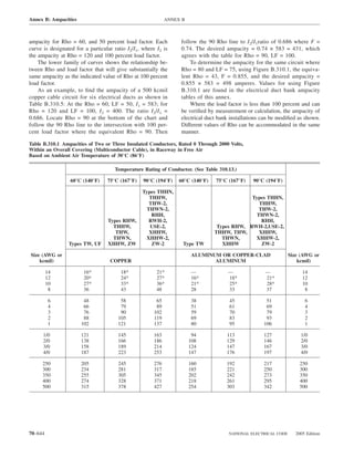
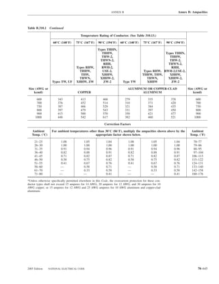
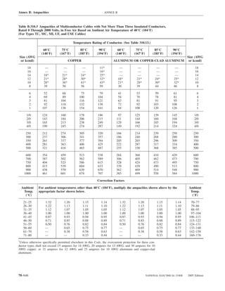
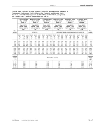
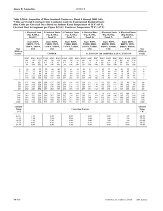
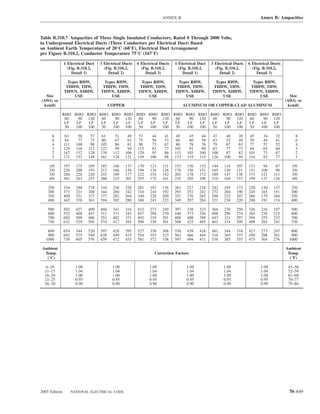
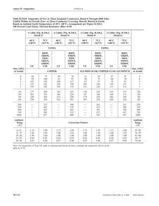
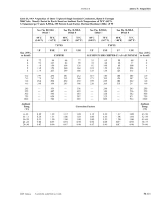
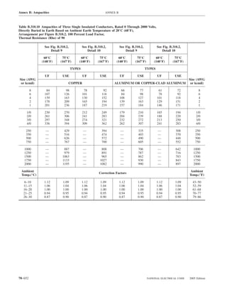
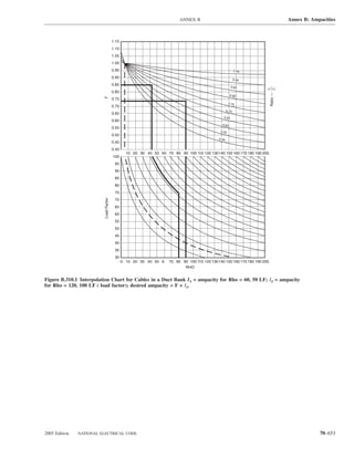
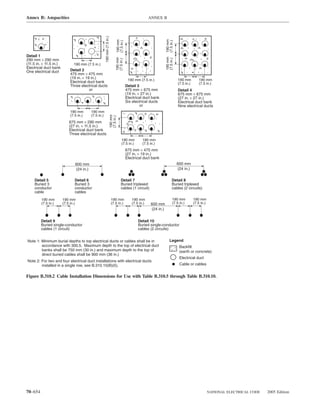
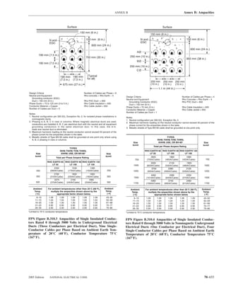
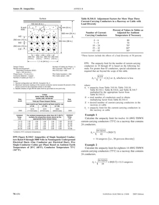
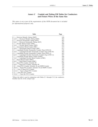

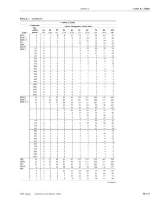
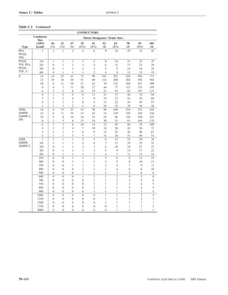
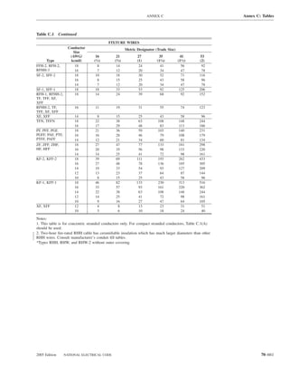
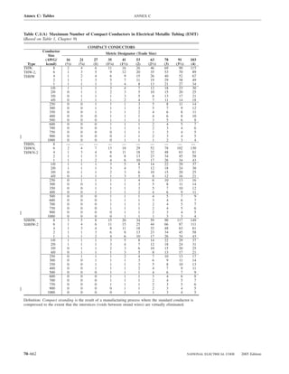
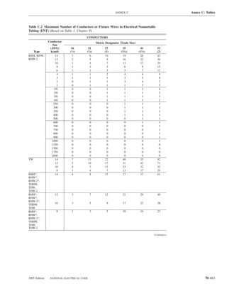
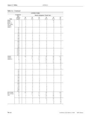
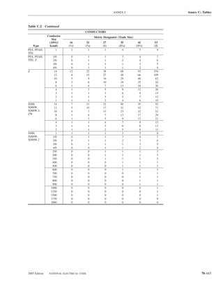
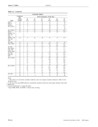
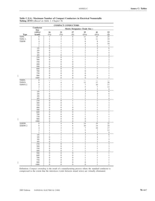
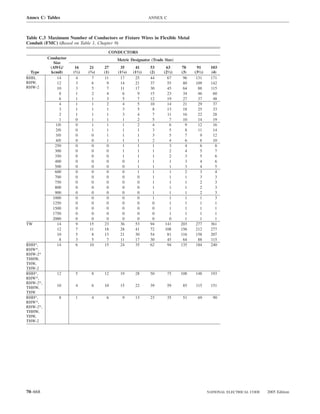


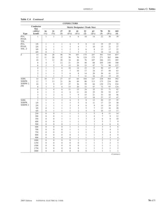

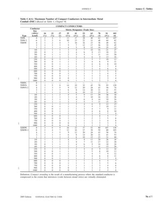
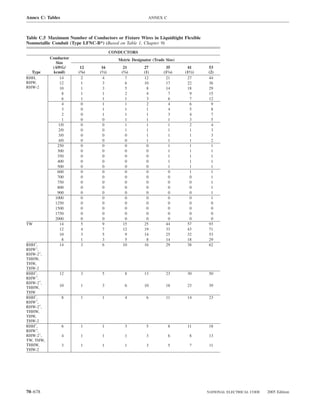
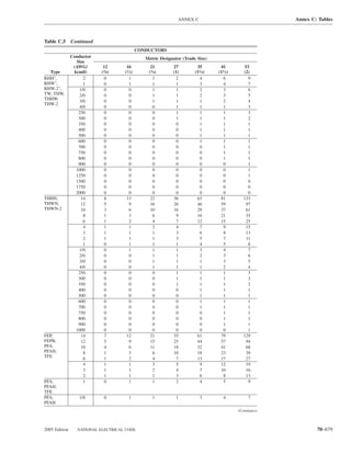
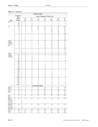
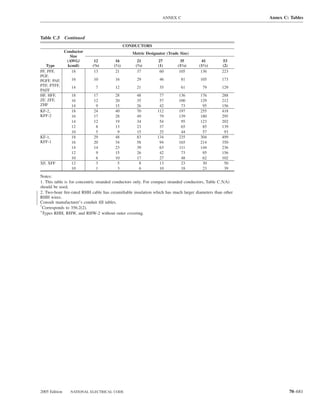
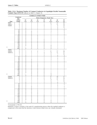
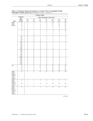
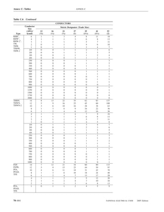
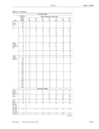
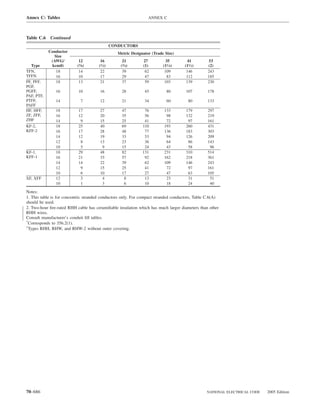
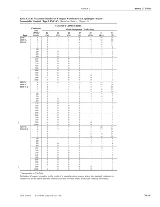
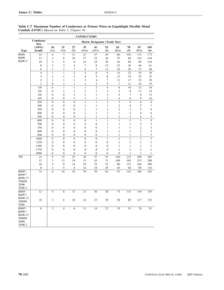


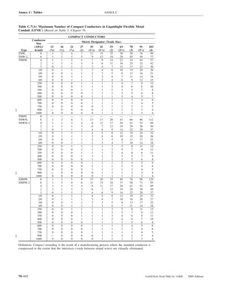
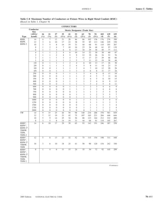
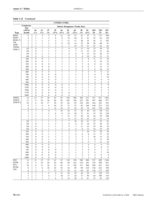

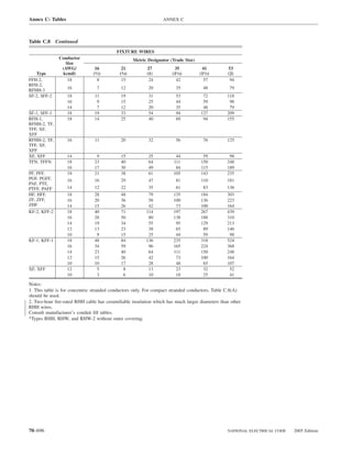
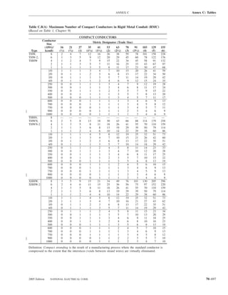
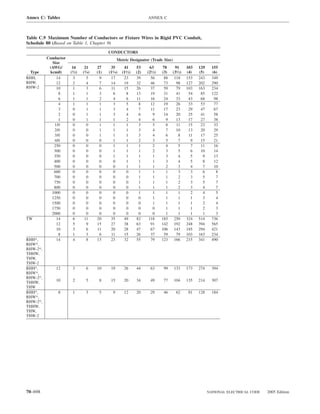
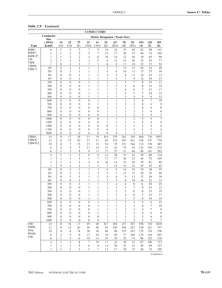
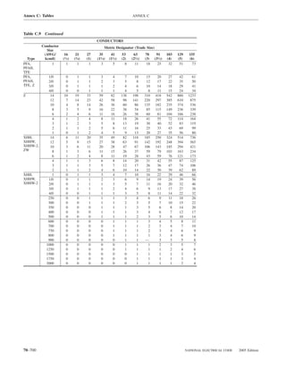
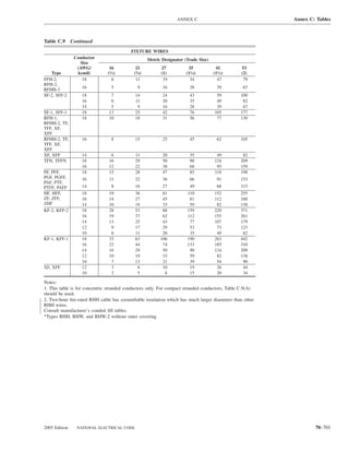
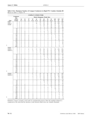

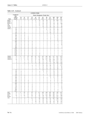


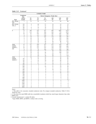
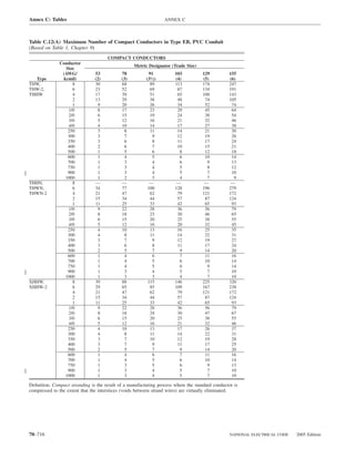
![ANNEX D Annex D: Examples
Annex D Examples
This annex is not a part of the requirements of this NFPA document but is included for informational purposes only.
Selection of Conductors. In the following examples, the results are Calculated Load for Neutral
generally expressed in amperes (A). To select conductor sizes, refer to the 14,550 VA ÷ 240 V = 60.6 A
0 through 2000 volt (V) ampacity tables of Article 310 and the rules of
310.15 that pertain to these tables.
Example D1(b) One-Family Dwelling
Voltage. For uniform application of Articles 210, 215, and 220, a
nominal voltage of 120, 120/240, 240, and 208Y/120 V is used in calcu- Assume same conditions as Example No. D1(a), plus addition of one 6-A,
lating the ampere load on the conductor. 230-V, room air-conditioning unit and one 12-A, 115-V, room air-conditioning
Fractions of an Ampere. Except where the calculations result in a unit,* one 8-A, 115-V, rated waste disposer, and one 10-A, 120-V, rated
major fraction of an ampere (0.5 or larger), such fractions are permitted to dishwasher. See Article 430 for general motors and Article 440, Part VII, for
be dropped. air-conditioning equipment. Motors have nameplate ratings of 115 V and
Power Factor. Calculations in the following examples are based, for 230 V for use on 120-V and 240-V nominal voltage systems.
convenience, on the assumption that all loads have the same power factor *(For feeder neutral, use larger of the two appliances for unbalance.)
(PF). From Example D1(a), feeder current is 78 A (3-wire, 240 V).
Ranges. For the calculation of the range loads in these examples, Line A Neutral Line B
Column C of Table 220.55 has been used. For optional methods, see
Columns A and B of Table 220.55. Except where the calculations result in Amperes from Example D1(a) 78 61 78
a major fraction of a kilowatt (0.5 or larger), such fractions are permitted One 230-V air conditioner 6 — 6
to be dropped. One 115-V air conditioner and 12 12 10
SI Units. For metric conversions, 0.093 m2 = 1 ft2 and 0.3048 m = 1 ft. 120-V dishwasher
One 115-V disposer — 8 8
Example D1(a) One-Family Dwelling 25% of largest motor 3 3 2
(see 430.24)
The dwelling has a floor area of 1500 ft2, exclusive of an unfinished cellar not
adaptable for future use, unfinished attic, and open porches. Appliances are a Total amperes per line 99 84 104
12-kW range and a 5.5-kW, 240-V dryer. Assume range and dryer kW ratings Therefore, the service would be rated 110 A.
equivalent to kVA ratings in accordance with 220.54 and 220.55.
Calculated Load [see 220.40]
Example D2(a) Optional Calculation for One-Family
General Lighting Load: 1500 ft2 at 3 VA per ft2 = 4500 VA Dwelling, Heating Larger Than Air Conditioning
Minimum Number of Branch Circuits Required [see 210.11(A)] [see 220.82]
General Lighting Load: 4500 VA ÷ 120 V = 37.5 A The dwelling has a floor area of 1500 ft2, exclusive of an unfinished cellar
This requires three 15-A, 2-wire or two 20-A, 2-wire circuits. not adaptable for future use, unfinished attic, and open porches. It has a
Small Appliance Load: Two 2-wire, 20-A circuits [see 210.11(C)(1)] 12-kW range, a 2.5-kW water heater, a 1.2-kW dishwasher, 9 kW of
Laundry Load: One 2-wire, 20-A circuit [see 210.11(C)(2)] electric space heating installed in five rooms, a 5-kW clothes dryer, and a
Bathroom Branch Circuit: One 2-wire, 20-A circuit (no additional load 6-A, 230-V, room air-conditioning unit. Assume range, water heater, dish-
calculation is required for this circuit) [see 210.11(C)(3)] washer, space heating, and clothes dryer kW ratings equivalent to kVA.
Minimum Size Feeder Required [see 220.40] Air Conditioner kVA Calculation
General Lighting 4,500 VA
Small Appliance 3,000 VA 6 A × 230 V ÷ 1000 = 1.38 kVA
Laundry 1,500 VA This 1.38 kVA [item 1 from 220.82(C)] is less than 40% of 9 kVA of sepa-
rately controlled electric heat [item 6 from 220.82(C)], so the 1.38 kVA need
Total 9,000 VA
3000 VA at 100% 3,000 VA not be included in the service calculation.
9000 VA – 3000 VA = 6000 VA at 35% 2,100 VA General Load
Net Load 5,100 VA 1500 ft2 at 3 VA 4,500 VA
Range (see Table 220.19) 8,000 VA Two 20-A appliance outlet circuits at 1500 VA each 3,000 VA
Dryer Load (see Table 220.54 ) 5,500 VA Laundry circuit 1,500 VA
Range (at nameplate rating) 12,000 VA
Net Calculated Load 18,600 VA Water heater 2,500 VA
Dishwasher 1,200 VA
Clothes dryer 5,000 VA
Net Calculated Load for 120/240-V, 3-wire, single-phase service or
feeder Total 29,700 VA
18,600 VA ÷ 240 V = 77.5 A
Application of Demand Factor [see 220.82(B)]
Sections 230.42(B) and 230.79 require service conductors and disconnect-
ing means rated not less than 100 amperes. First 10 kVA of general load at 100% 10,000 VA
Remainder of general load at 40% 7,880 VA
Calculation for Neutral for Feeder and Service (19.7 kVA × 0.4)
Lighting and Small Appliance Load 5,100 VA
Range: 8000 VA at 70% (see 220.61) 5,600 VA Total of general load 17,880 VA
Dryer: 5500 VA at 70% (see 220.61) 3,850 VA 9 kVA of heat at 40% (9000 VA × 0.4) = 3,600 VA
Total 14,550 VA Total 21,480 VA
2005 Edition NATIONAL ELECTRICAL CODE 70–717](https://image.slidesharecdn.com/nechandbookversin2005compacta-100921141249-phpapp02/85/Nec-handbook-version-2005-compacta-720-320.jpg)
![Annex D: Examples ANNEX D
Calculated Load for Service Size 1500 ft2 at 3 VA 4,500 VA
Three 20-A circuits at 1500 VA 4,500 VA
21.48 kVA = 21,480 VA
21,480 VA ÷ 240 V = 89.5 A Subtotal 9,000 VA
Therefore, the minimum service rating would be 100 A in accordance with 3000 VA at 100% 3,000 VA
230.42 and 230.79. 9000 VA − 3000 VA = 6000 VA at 35% 2,100 VA
Feeder Neutral Load, per 220.61 Subtotal 5,100 VA
1500 ft2 at 3 VA 4,500 VA
Three 20-A circuits at 1500 VA 4,500 VA Two 4-kVA ovens plus one 5.1-kVA cooking unit = 13.1 kVA. Table
220.55 permits 55% demand factor or 13.1 kVA × 0.55 = 7.2 kVA feeder
Total 9,000 VA capacity.
3000 VA at 100% 3,000 VA
9000 VA − 3000 VA = 6000 VA at 35% 2,100 VA Subtotal from above 5,100 VA
Ovens and cooking unit: 7200 VA × 70% for neutral load 5,040 VA
Subtotal 5,100 VA Clothes washer/dryer: 5 kVA × 70% for neutral load 3,500 VA
Range: 8 kVA at 70% 5,600 VA Dishwasher 1,200 VA
Clothes dryer: 5 kVA at 70% 3,500 VA
Dishwasher 1,200 VA Total 14,840 VA
Total 15,400 VA Calculated Load for Neutral
14,840 VA ÷ 240 V = 61.83 A (use 62 A)
Calculated Load for Neutral
15,400 VA ÷ 240 V= 64.2 A Example D2(c) Optional Calculation for One-Family
Dwelling with Heat Pump (Single-Phase, 240/120-Volt
Service) (see 220.82)
Example D2(b) Optional Calculation for One-Family
The dwelling has a floor area of 2000 ft2, exclusive of an unfinished cellar
Dwelling, Air Conditioning Larger Than Heating
not adaptable for future use, unfinished attic, and open porches. It has a
[see 220.82(A) and 220.82(C)]
12-kW range, a 4.5-kW water heater, a 1.2-kW dishwasher, a 5-kW clothes
The dwelling has a floor area of 1500 ft2, exclusive of an unfinished cellar dryer, and a 21⁄2-ton (24-A) heat pump with 15 kW of backup heat.
not adaptable for future use, unfinished attic, and open porches. It has two
Heat Pump kVA Calculation
20-A small appliance circuits, one 20-A laundry circuit, two 4-kW wall-
mounted ovens, one 5.1-kW counter-mounted cooking unit, a 4.5-kW wa- 24 A × 240 V ÷ 1000 = 5.76 kVA
ter heater, a 1.2-kW dishwasher, a 5-kW combination clothes washer and
This 5.76 kVA is less than 15 kVA of the backup heat; therefore, the heat
dryer, six 7-A, 230-V room air-conditioning units, and a 1.5-kW perma-
pump load need not be included in the service calculation [see 220.82(C)].
nently installed bathroom space heater. Assume wall-mounted ovens,
counter-mounted cooking unit, water heater, dishwasher, and combination General Load
clothes washer and dryer kW ratings equivalent to kVA. 2000 ft2 at 3 VA 6,000 VA
Air Conditioning kVA Calculation Two 20-A appliance outlet circuits at 3,000 VA
1500 VA each
Total amperes = 6 units × 7 A = 42 A Laundry circuit 1,500 VA
42 A × 240 V ÷ 1000 = 10.08 kVA (assume PF = 1.0) Range (at nameplate rating) 12,000 VA
Water heater 4,500 VA
Load Included at 100% Dishwasher 1,200 VA
Air Conditioning: Included below [see item 1 in 220.82(C)] Clothes dryer 5,000 VA
Space Heater: Omit [see item 5 in 220.82(C)]
Subtotal general load 33,200 VA
General Load First 10 kVA at 100% 10,000 VA
1500 ft2 at 3 VA 4,500 VA Remainder of general load at 40%
Two 20-A small appliance 23,200 VA × 0.4) 9,280 VA
circuits at 1500 VA each 3,000 VA
Laundry circuit 1,500 VA Total net general load 19,280 VA
Two ovens 8,000 VA
One cooking unit 5,100 VA
Water heater 4,500 VA Heat Pump and Supplementary Heat*
Dishwasher 1,200 VA
Washer/dryer 5,000 VA 240 V × 24 A = 5760 VA
15 kW Electric Heat:
Total general load 32,800 VA
First 10 kVA at 100% 10,000 VA 5760 VA + (15,000 VA × 65%) = 5.76 kVA + 9.75 kVA = 15.51 kVA
Remainder at 40%
(22.8 kVA × 0.4 × 1000) 9,120 VA *If supplementary heat is not on at same time as heat pump, heat
pump kVA need not be added to total.
Subtotal general load 19,120 VA Totals
Air conditioning 10,080 VA Net general load 19,280 VA
Heat pump and supplementary heat 15,510 VA
Total 29,200 VA
Total 34,790 VA
Calculated Load for Service
29,200 VA ÷ 240 V = 122 A (service rating) Calculated Load for Service
Feeder Neutral Load, per 220.61 34.79 kVA × 1000 ÷ 240 V= 144.96 A
Assume that the two 4-kVA wall-mounted ovens are supplied by one branch Therefore, this dwelling unit would be permitted to be served by a 150-A
circuit, the 5.1-kVA counter-mounted cooking unit by a separate circuit. service.
70–718 NATIONAL ELECTRICAL CODE 2005 Edition](https://image.slidesharecdn.com/nechandbookversin2005compacta-100921141249-phpapp02/85/Nec-handbook-version-2005-compacta-721-320.jpg)
![ANNEX D Annex D: Examples
Example D3 Store Building Minimum Size Feeders (or Service Conductors) Required
A store 50 ft by 60 ft, or 3000 ft2, has 30 ft of show window. There are a [see 215.2, 230.42(A)]
total of 80 duplex receptacles. The service is 120/240 V, single phase For 120/240 V, 3-wire system,
3-wire service. Actual connected lighting load is 8500 VA. 32,450 VA ÷ 240 V = 135 A
Calculated Load (see 220.40) Service or feeder conductor is 1/0 Cu per 215.3 and Table 310.16 (with
75°C terminations).
Noncontinuous Loads
Receptacle Load (see 220.44)
80 receptacles at 180 VA 14,400 VA Example D3(a) Industrial Feeders in
10,000 VA at 100% 10,000 VA a Common Raceway
14,400 VA − 10,000 VA = 4400 at 50% 2,200 VA An industrial multi-building facility has its service at the rear of its main
building, and then provides 480Y/277-volt feeders to additional buildings
Subtotal 12,200 VA
Continuous Loads behind the main building in order to segregate certain processes. The
General Lighting* facility supplies its remote buildings through a partially enclosed access
3000 ft2 at 3 VA per ft2 9,000 VA corridor that extends from the main switchboard rearward along a path
Show Window Lighting Load that provides convenient access to services within 15 m (50 ft) of each
30 ft at 200 VA per ft 6,000 VA additional building supplied. Two building feeders share a common race-
Outside Sign Circuit [see 220.14(F)] 1,200 VA way for approximately 45 m (150 ft) and run in the access corridor along
with process steam and control and communications cabling. The steam
Subtotal 16,200 VA raises the ambient temperature around the power raceway to as much as
Subtotal from noncontinuous 12,200 VA 35°C. At a tee fitting, the individual building feeders then run to each of
the two buildings involved. The feeder neutrals are not connected to the
Total noncontinuous loads + equipment grounding conductors in the remote buildings. All distribution
continuous loads = 28,400 VA equipment terminations are listed as being suitable for 75°C connections.
Each of the two buildings has the following loads:
*In the example, 125% of the actual connected lighting load (8500 VA × 1.25 Lighting, 11,600 VA, comprised of electric-discharge luminaires con-
= 10,625 VA) is less than 125% of the load from Table 220.12, so the mini- nected at 277 V
mum lighting load from Table 220.12 is used in the calculation. Had the actual
lighting load been greater than the value calculated from Table 220.12, 125% Receptacles, 22 125-volt, 20 ampere receptacles on general-purpose
of the actual connected lighting load would have been used. branch circuits, supplied by separately derived systems in each of
the buildings
Minimum Number of Branch Circuits Required
1-Air compressor, 460 volt, three phase, 7.5 hp
General Lighting: Branch circuits need only be installed to supply the
1-Grinder, 460 volt, three phase,1.5 hp
actual connected load [see 210.11(B)].
3-Welders, AC transformer type (nameplate: 23 amperes, 480 volts,
8500 VA × 1.25 = 10,625 VA
60 percent duty cycle)
10,625 VA ÷ 240 V = 44 A for 3-wire, 120/240 V
3-Industrial Process Dryers, 480 volt, three phase,15 kW each (assume
The lighting load would be permitted to be served by 2-wire or 3-wire, continuous use throughout certain shifts)
15- or 20-A circuits with combined capacity equal to 44 A or greater for
3-wire circuits or 88 A or greater for 2-wire circuits. The feeder capacity Determine the overcurrent protection and conductor size for the feeders in the
as well as the number of branch-circuit positions available for lighting common raceway, assuming the use of XHHW-2 insulation (90°C):
circuits in the panelboard must reflect the full calculated load of 9000 VA Calculated Load {Note: For reasonable precision, volt-ampere calculations
× 1.25 = 11,250 VA. are carried to three significant figures only; where loads are converted to
Show Window amperes, the results are rounded to the nearest ampere [see 220.5(B)]}.
6000 VA × 1.25 = 7500 VA Noncontinuous Loads
7500 VA ÷ 240 V = 31 A for 3-wire, 120/240 V Receptacle Load (see 220.44 )
22 receptacles at 180 VA 3,960 VA
The show window lighting is permitted to be served by 2-wire or 3-wire Welder Load [see 630.11(A), Table 630.11(A)]
circuits with a capacity equal to 31 A or greater for 3-wire circuits or 62 A Each welder: 480V × 23A × 0.78 = 8,610 VA
or greater for 2-wire circuits. All 3 welders: [see 630.11(B)] (demand factors 100%,
Receptacles required by 210.62 are assumed to be included in the 100%, 85% respectively)
receptacle load above if these receptacles do not supply the show window 8,610 VA + 8,610 VA + 7,320 VA = 24,500 VA
lighting load.
Subtotal, Noncontinuous Loads 28,500 VA
Receptacles Motor Loads (see 430.24, Table 430.250)
Receptacle Load:14,400 VA ÷ 240 V = 60 A for 3-wire, 120/240 V Air compressor: 11 A × 480 V × √3 = 9,150 VA
The receptacle load would be permitted to be served by 2-wire or Grinder: 3 A × 480 V × √3 = 2,490 VA
Largest motor, additional 25%: 2,290 VA
3-wire circuits with a capacity equal to 60 A or greater for 3-wire circuits
or 120 A or greater for 2-wire circuits. Subtotal, Motor Loads 13,900 VA
Minimum Size Feeder (or Service) Overcurrent Protection
[see 215.3 or 230.90] By using 430.24, the motor loads and the noncontinuous loads can be
combined for the remaining calculation.
Subtotal noncontinuous loads 12,200 VA Subtotal for load calculations, Noncontinuous Loads 42,400 VA
Subtotal continuous load at 125%
(16,200 VA × 1.25) 20,250 VA Continuous Loads
General Lighting 11,600 VA
Total 32,450 VA 3 Industrial Process Dryers 15 kW each 45,000 VA
Subtotal, Continuous Loads: 56,600 VA
32,450 VA ÷ 240 V = 135 A
The next higher standard size is 150 A (see 240.6).
2005 Edition NATIONAL ELECTRICAL CODE 70–719](https://image.slidesharecdn.com/nechandbookversin2005compacta-100921141249-phpapp02/85/Nec-handbook-version-2005-compacta-722-320.jpg)
![Annex D: Examples ANNEX D
Overcurrent protection (see 215.3) Although the neutral runs between the main switchboard and the building
panelboard, likely terminating on a busbar at both locations, the busbar con-
The overcurrent protective device must accommodate 125% of the con-
nections are part of listed devices and are not “separately installed pressure
tinuous load, plus the noncontinuous load:
devices.” Therefore 110.14(C)(2) does not apply, and the normal termination
Continuous load 56,600 VA temperature limits apply. In addition, the listing requirement to gain exemp-
Noncontinuous load 42,400 VA tion from the additional sizing allowance under continuous loading (see
215.3Exception) covers not just the overcurrent protective device, but its en-
Subtotal, actual load [actual load in amperes: 99,000 VA tire assembly as well. Therefore, since the lighting load is continuous, the
99,000 VA ÷ (480V × √3) = 119 A] minimum conductor size is based on 1.25 × (11,600 VA / 277V) = 52 am-
(25% of 56,600 VA) (See 215.3) 14,200 VA peres, to be evaluated under the 75°C column of Table 310.16. The minimum
size of the neutral is 6 AWG. This size is also the minimum size required by
Total VA 113,200 VA 215.2(A)(1), because the minimum size equipment grounding conductor for a
150 ampere circuit, as covered in Table 250.122, is 6 AWG.
Conversion to amperes using three significant figures:
113,200 VA / (480V × √3) = 136 A
Minimum size overcurrent protective device: 136 A Example D4(a) Multifamily Dwelling
Minimum standard size overcurrent protective A multifamily dwelling has 40 dwelling units.
device (see 240.6): 150 amperes Meters are in two banks of 20 each with individual feeders to each dwell-
ing unit.
Where the overcurrent protective device and its assembly are listed for
operation at 100 percent of its rating, a 125 ampere overcurrent protective One-half of the dwelling units are equipped with electric ranges not ex-
device would be permitted. However, overcurrent protective device assem- ceeding 12 kW each. Assume range kW rating equivalent to kVA rating in
accordance with 220.55. Other half of ranges are gas ranges.
blies listed for 100 percent of their rating are typically not available at the
125-ampere rating. (See 215.3 Exception.) Area of each dwelling unit is 840 ft2.
Laundry facilities on premises are available to all tenants. Add no circuit
Ungrounded Feeder Conductors to individual dwelling unit.
The conductors must independently meet requirements for (1) termina- Calculated Load for Each Dwelling Unit (see Article 220)
tions, and (2) conditions of use throughout the raceway run. General Lighting: 840 ft2 at 3 VA per ft2 = 2520 VA
Minimum size conductor at the overcurrrent device termination [see Special Appliance: Electric range (see 220.55) = 8000 VA
110.14(C) and 215.2(A)(1), using 75°C ampacity column in Table 310.16]: Minimum Number of Branch Circuits Required for Each Dwelling
1/0 AWG. Unit [see 210.11(A)]
Minimum size conductors in the raceway based on actual load [see General Lighting Load: 2520 VA ÷ 120 V = 21 A or two 15-A, 2-wire
Article 100, Ampacity, and 310.15(B)(2)(a) and correction factors to circuits; or two 20-A, 2-wire circuits
Table Table 310.16]: Small Appliance Load: Two 2-wire circuits of 12 AWG wire
[see 210.11(C)(1)]
99,000 VA / 0.7 / 0.96 = 147,000 VA
Range Circuit: 8000 VA ÷ 240 V = 33 A or a circuit of two 8 AWG
(70% = 310.15(B)(2)(a)) & (0.96 = Correction factors to Table 310.16) conductors and one 10 AWG conductor per 210.19(A)(3)
Conversion to amperes: Minimum Size Feeder Required for Each Dwelling Unit (see 215.2)
147,000 VA / (480V × √3) = 177 A Calculated Load (see Article 220):
General Lighting 2,520 VA
Note that the neutral conductors are counted as current-carrying con- Small Appliance (two 20-ampere circuits) 3,000 VA
ductors [see 310.15(B)(4)(c)] in this example because the discharge light-
ing has substantial nonlinear content. This requires a 2/0 AWG conductor Subtotal Calculated Load (without ranges) 5,520 VA
based on the 90°C column of Table 310.16 Therefore, the worst case is
given by the raceway conditions, and 2/0 AWG conductors must be used. Application of Demand Factor (see Table 220.42)
If the utility corridor was at normal temperatures [(30°C (86°F)], and if the First 3000 VA at 100% 3,000 VA
lighting at each building were supplied from the local separately derived 5520 VA − 3000 VA = 2520 VA at 35% 882 VA
system (thus requiring no neutrals in the supply feeders) the raceway
result (99,000 VA / 0.8 = 124,000 VA; 124,000 VA / (480V × √3) = 149 A, Net Calculated Load (without ranges) 3,882 VA
or a 1 AWG conductor @ 90°C) could not be used because the termination Range Load 8,000 VA
result (1/0 AWG based on the 75°C column of ) would become the worst
case, requiring the larger conductor. Net Calculated Load (with ranges) 11,882 VA
In every case, the overcurrent protective device shall provide overcur-
rent protection for the feeder conductors in accordance with their ampacity Size of Each Feeder (see 215.2)
as provided by this Code (see 240.4). A 90°C 2/0 AWG conductor has a
For 120/240-V, 3-wire system (without ranges)
Table 310.16 ampacity of 195 amperes. Adjusting for the conditions of use
(35°C ambient temperature, 8 current-carrying conductors in the common Net calculated load of 3882 VA ÷ 240 V = 16.2 A
raceway), For 120/240-V, 3-wire system (with ranges)
195 amperes × 0.96 × 0.7 = 131 A Net calculated load, 11,882 VA ÷ 240 V = 49.5 A
The 150-ampere circuit breaker protects the 2/0 AWG feeder conduc-
tors, because 240.4(B) permits the use of the next higher standard size Feeder Neutral
overcurrent protective device. Note that the feeder layout precludes the Lighting and Small Appliance Load 3,882 VA
application of 310.15(A)(2) Exception. Range Load: 8000 VA at 70% (see 220.61) 5,600 VA
Feeder Neutral Conductor (see 220.61) (only for apartments with electric range) 5,600 VA
Because 210.11(B) does not apply to these buildings, the load cannot be Net Calculated Load (neutral) 9,482 VA
assumed to be evenly distributed across phases. Therefore the maximum
imbalance must be assumed to be the full lighting load in this case, or
11,600 VA. (11,600 VA / 277V = 42 amperes.) The ability of the neutral to Calculated Load for Neutral
return fault current [see 250.32(B)(2)(2)] is not a factor in this calculation. 9482 VA ÷ 240 V= 39.5 A
70–720 NATIONAL ELECTRICAL CODE 2005 Edition](https://image.slidesharecdn.com/nechandbookversin2005compacta-100921141249-phpapp02/85/Nec-handbook-version-2005-compacta-723-320.jpg)
![ANNEX D Annex D: Examples
Minimum Size Feeders Required from Service Equipment to Meter Further Demand Factor [see 220.61(B)]
Bank (For 20 Dwelling Units — 10 with Ranges)
200 A at 100% 200 A
Total Calculated Load: 390 A − 200 A = 190 A at 70% 133 A
Lighting and Small Appliance
20 units × 5520 VΑ 110,400 VA Net Calculated Load (neutral) 333 A
Application of Demand Factor
First 3000 VA at 100% 3,000 VA [See Table 310.16 through Table 310.21, and 310.15(B)(2) and (B)(4).]
110,400 VA − 3000 VA = 107,400 VA at 35% 37,590 VA
Net Calculated Load 40,590 VA
Example D4(b) Optional Calculation for
Range Load: 10 ranges (less than 12 kVA) (see Col. C, 25,000 VA Multifamily Dwelling
Table 220.55) A multifamily dwelling equipped with electric cooking and space heating
or air conditioning has 40 dwelling units.
Net Calculated Load (with ranges) 65,590 VA Meters are in two banks of 20 each plus house metering and individual
feeders to each dwelling unit.
Net calculated load for 120/240-V, 3-wire system, Each dwelling unit is equipped with an electric range of 8-kW name-
plate rating, four 1.5-kW separately controlled 240-V electric space heat-
65,590 VA ÷ 240 V = 273 A ers, and a 2.5-kW, 240-V electric water heater. Assume range, space
Feeder Neutral heater, and water heater kW ratings equivalent to kVA.
A common laundry facility is available to all tenants [see 210.52(F),
Lighting and Small Appliance Load 40,590 VA Exception No. 1].
Range Load: 25,000 VA at 70% [see 220.61(B)] 17,500 VA Area of each dwelling unit is 840 ft2.
Calculated Load (neutral) 58,090 VA Calculated Load for Each Dwelling Unit (see Article 220)
General Lighting Load:
Calculated Load for Neutral 840 ft2 at 3 VA per ft2 2,520 VA
Electric range 8,000 VA
58,090 VA ÷ 240 V = 242 A Electric heat: 6 kVA (or air conditioning 6,000 VA
Further Demand Factor [220.61(B)] if larger)
200 A at 100% 200 A Electric water heater 2,500 VA
242 A − 200 A = 42 A at 70% 29 A
Net Calculated Load (neutral) 229 A Minimum Number of Branch Circuits Required for Each Dwelling Unit
General Lighting Load: 2520 VA ÷ 120 V = 21 A or two 15-A, 2-wire
Minimum Size Main Feeders (or Service Conductors) Required circuits, or two 20-A, 2-wire circuits
(Less House Load) (For 40 Dwelling Units — 20 with Ranges)
Small Appliance Load: Two 2-wire circuits of 12 AWG [see 210.11(C)(1)]
Total Calculated Load:
Lighting and Small Appliance Load Range Circuit (See Table 220.55, Column B):
40 units × 5520 VΑ 220,800 VA
8000 VA × 80% ÷ 240 V = 27 A on a circuit of three
10 AWG conductors per 210.19(A)(3)
Application of Demand Factor Space Heating: 6000 VA ÷ 240 V = 25 A
(from Table 220.42) Number of circuits (see 210.11)
Minimum Size Feeder Required for Each Dwelling Unit (see 215.2)
First 3000 VA at 100% 3,000 VA
Next 120,000 VA − 3000 VA = 117,000 VA at 35% 40,950 VA Calculated Load (see Article 220):
Remainder 220,800 VA − 120,000 VA = 25,200 VA
100,800 VA at 25% General Lighting 2,520 VA
Small Appliance (two 20-A circuits) 3,000 VA
Net Calculated Load 69,150 VA
Range Load: 20 ranges (less than 12 kVA) Subtotal Calculated Load (without range 5,520 VA
(see Col. C, Table 220.55) 35,000 VA and space heating)
Net Calculated Load 104,150 VA
For 120/240-V, 3-wire system Application of Demand Factor
Net calculated load of 104,150 VA ÷ 240 V = 434 A First 3000 VA at 100% 3,000 VA
5520 VA − 3000 VA = 2520 VA at 35% 882 VA
Feeder Neutral
Net Calculated Load 3,882 VA
Lighting and Small Appliance Load 69,150 VA (without range and space heating)
Range: 35,000 VA at 70% 24,500 VA Range 6,400 VA
[see 220.61(B)]
Space Heating (see 220.51) 6,000 VA
Calculated Load (neutral) 93,650 VA Water Heater 2,500 VA
Net Calculated Load (for individual dwelling unit) 18,782 VA
93,650 VA ÷ 240 V = 390 A
2005 Edition NATIONAL ELECTRICAL CODE 70–721](https://image.slidesharecdn.com/nechandbookversin2005compacta-100921141249-phpapp02/85/Nec-handbook-version-2005-compacta-724-320.jpg)
![Annex D: Examples ANNEX D
Size of Each Feeder Feeder Neutral Load of Main Feeder (Less House Load)
For 120/240-V, 3-wire system, (For 40 Dwelling Units)
Net calculated load of 18,782 VA ÷ 240 V = 78 A
Feeder Neutral (see 220.61) Lighting and Small Appliance Load
40 units × 5520 VΑ 220,800 VA
Lighting and Small Appliance 3,882 VA First 3000 VA at 100% 3,000 VA
Range Load: 6400 VA at 70% [see 220.61(B)] 4,480 VA Next 120,000 VA − 3000 VA = 117,000 VA at 35% 40,950 VA
Space and Water Heating (no neutral): 240 V 0 VA Remainder 220,800 VA − 120,000 VA = 100,800 VA at 25,200 VA
25%
Net Calculated Load (neutral) 8,362 VA
Net Calculated Load 69,150 VA
40 ranges: 55,000 VA at 70% 38,500 VA
Calculated Load for Neutral [see Table 220.55 and 220.61(B)]
8362 VA ÷ 240 V = 35 Α Total 107,650 VA
Minimum Size Feeder Required from Service Equipment to Meter
Bank (For 20 Dwelling Units) 107,650 VA ÷ 240 V = 449 A
Total Calculated Load:
Lighting and Small Appliance Load Further Demand Factor [see 220.61(B)]
20 units × 5520 VΑ 110,400 VA
Water and Space Heating Load
20 units × 8500 VΑ 170,000 VA
Range Load: 20 × 8000 VΑ 160,000 VA First 200 A at 100% 200 A
Balance: 449 − 200 A = 249 A at 70% 174 A
Net Calculated Load (20 dwelling units) 440,400 VA
Total 374 A
Net Calculated Load Using Optional Calculation
(see Table 220.84)
440,400 VA × 0.38 167,352 VA
167,352 VA ÷ 240 V = 697 A
Minimum Size Main Feeder Required (Less House Load) (For 40 Example D5(a) Multifamily Dwelling Served at
Dwelling Units) 208Y/120 Volts, Three Phase
All conditions and calculations are the same as for the multifamily dwell-
Calculated Load: ing [Example D4(a)] served at 120/240 V, single phase except as follows:
Lighting and Small Appliance Load Service to each dwelling unit would be two phase legs and neutral.
40 units × 5520 VΑ 220,800 VA
Water and Space Heating Load 340,000 VA Minimum Number of Branch Circuits Required for Each Dwelling
40 units × 8500 VΑ Unit (see 210.11)
Range: 40 ranges × 8000 VΑ 320,000 VA
Range Circuit: 8000 VA ÷ 208 V = 38 A or a circuit of two 8 AWG
Net Calculated Load (40 dwelling units) 880,800 VA conductors and one 10 AWG conductor per 210.19(A)(3)
Minimum Size Feeder Required for Each Dwelling Unit (see 215.2)
Net Calculated Load Using Optional Calculation (see Table 220.84) For 120/208-V, 3-wire system (without ranges),
880,800 VA × 0.28 = 246,624 VA Net calculated load of 3882 VA ÷ 2 legs ÷ 120 V/leg = 16.2 A
246,624 VA ÷ 240 V = 1028 A For 120/208-V, 3-wire system (with ranges),
Net calculated load (range) of 8000 VA ÷ 208 V = 38.5 A
Feeder Neutral Load for Feeder from Service Equipment to Meter
Total load (range + lighting) = 38.5 A + 16.2 A = 54.7 A
Bank (For 20 Dwelling Units)
Feeder neutral: (range) of 8000 VA × 70% = 5600 VA ÷ 208 V = 26.9 A
Total load: (range + lighting) = 26.9 A + 16.2 A = 43.1 A
Lighting and Small Appliance Load
20 units × 5520 VΑ 110,400 VA Minimum Size Feeders Required from Service Equipment to Meter
First 3000 VA at 100% 3,000 VA Bank (For 20 Dwelling Units — 10 with Ranges)
110,400 VA − 3000 VA = 107,400 VA at 35% 37,590 VA
For 208Y/120-V, 3-phase, 4-wire system,
Net Calculated Load 40,590 VA Ranges: Maximum number between any two phase legs = 4
20 ranges: 35,000 VA at 70% 24,500 VA 2 × 4 = 8.
[see Table 220.55 and Table 220.61(B)] Table 220.55 demand = 23,000 VA
Per phase demand = 23,000 VA ÷ 2 = 11,500 VA
Total 65,090 VA Equivalent 3-phase load = 34,500 VA
Net Calculated Load (total):
65,090 VA ÷ 240 V = 271 A 40,590 VA + 34,500 VA = 75,090 VA
75,090 VA ÷ (208 V)(1.732) = 208.4 A
Further Demand Factor [see 220.61(B)] Feeder Neutral Size
Net Calculated Lighting and Appliance Load & Equivalent Range Load:
First 200 A at 100% 200 A
Balance: 271 A − 200 A = 71 A at 70% 50 A 40,590 VA + (34,500 VA at 70%) = 64,700 VA
Net Calculated Neutral Load:
Total 250 amperes
64,700 VA ÷ (208 V)(1.732) = 179.7 A
70–722 NATIONAL ELECTRICAL CODE 2005 Edition](https://image.slidesharecdn.com/nechandbookversin2005compacta-100921141249-phpapp02/85/Nec-handbook-version-2005-compacta-725-320.jpg)
![ANNEX D Annex D: Examples
Minimum Size Main Feeder (Less House Load) Further Demand Factor [see 220.61(B)]
(For 40 Dwelling Units — 20 with Ranges)
For 208Y/120-V, 3-phase, 4-wire system, 200 A at 100% 200.0 A
Ranges: 298.8 A − 200 A = 98.8 A at 70% 69.2 A
Maximum number between any two phase legs = 7
2 × 7 = 14. Net Calculated Load (neutral) 269.2 A
Table 220.55 demand = 29,000 VA
Per phase demand = 29,000 VA ÷ 2 = 14,500 VA
Equivalent 3-phase load = 43,500 VA
Net Calculated Load (total):
69,150 VA + 43,500 VA = 112,650 VA Example D6 Maximum Demand for Range Loads
112,650 VA ÷ (208 V)(1.732) = 312.7 A
Table 220.55, Column C applies to ranges not over 12 kW. The applica-
Main Feeder Neutral Size: tion of Note 1 to ranges over 12 kW (and not over 27 kW) and Note 2 to
69,150 VA + (43,500 VA at 70%) = 99,600 VA ranges over 83⁄4 kW (and not over 27 kW) is illustrated in the following
99,600 VA ÷ (208 V)(1.732) = 276.5 A two examples.
A. Ranges All the Same Rating (see Table 220.55, Note 1)
Further Demand Factor (see 220.61) Assume 24 ranges, each rated 16 kW.
From Table 220.55, Column C, the maximum demand for 24 ranges of
12-kW rating is 39 kW. 16 kW exceeds 12 kW by 4.
200 A at 100% 200.0 A 5% × 4 = 20% (5% increase for each kW in excess of 12)
276.5 A − 200 A = 76.5 A at 70% 53.6 A 39 kW × 20% = 7.8 kW increase
39 + 7.8 = 46.8 kW (value to be used in selection of feeders)
Net Calculated Load (neutral) 253.6 A
B. Ranges of Unequal Rating (see Table 220.55, Note 2)
Assume 5 ranges, each rated 11 kW; 2 ranges, each rated 12 kW; 20
ranges, each rated 13.5 kW; 3 ranges, each rated 18 kW.
5 ranges × 12 kW = 60 kW (use 12 kW
Example D5(b) Optional Calculation for Multifamily for range rated less than 12)
Dwelling Served at 208Y/120 Volts, Three Phase 2 ranges × 12 kW = 24 kW
20 ranges × 13.5 kW = 270 kW
All conditions and calculations are the same as for Optional Calculation 3 ranges × 18 kW = 54 kW
for the Multifamily Dwelling [Example D4(b)] served at 120/240 V, single
phase except as follows: 30 ranges, Total kW = 408 kW
Service to each dwelling unit would be two phase legs and neutral.
Minimum Number of Branch Circuits Required for Each Dwelling 408 ÷ 30 ranges = 13.6 kW (average to be used for calculation)
Unit (see 210.11)
Range Circuit (see Table 220.55 Column B): 8000 VA at 80% ÷ 208 V = From Table 220.55, Column C, the demand for 30 ranges of 12-kW rating
30.7 A or a circuit of two 8 AWG conductors and one 10 AWG conduc- is 15 kW + 30 (1 kW × 30 ranges) = 45 kW. 13.6 kW exceeds 12 kW
tor per 210.19(A)(3) by 1.6 kW (use 2 kW).
Space Heating: 6000 VA ÷ 208 V = 28.8 A 5% × 2 = 10% (5% increase for each kW in excess of 12 kW)
Two 20-ampere, 2-pole circuits required, 12 AWG conductors
45 kW × 10% = 4.5 kW increase
Minimum Size Feeder Required for Each Dwelling Unit 45 kW + 4.5 kW = 49.5 kW (value to be used in selection of feeders)
120/208-V, 3-wire circuit
Net calculated load of 18,782 VA ÷ 208 V = 90.3 A
Net calculated load (lighting line to neutral): Example D8 Motor Circuit Conductors, Overload
Protection, and Short-Circuit and Ground-Fault
3882 VA ÷ 2 legs ÷ 120 V per leg = 16.2 amperes
Protection (see 240.6, 430.6, 430.22, 430.23, 430.24,
Line to line = 14,900 VA ÷ 208 V = 71.6 A 430.32, 430.52, and 430.62, Table 430.52 and Table
Total load = 16.2 A + 71.6 A = 87.8 A 430.250)
Minimum Size Feeder Required for Service Equipment to Meter Bank Determine the minimum required conductor ampacity, the motor overload
(For 20 Dwelling Units) protection, the branch-circuit short-circuit and ground-fault protection, and
the feeder protection, for three induction-type motors on a 480-V, 3-phase
Net Calculated Load feeder, as follows:
167,352 VA ÷ (208 V)(1.732) = 464.9 A (a) One 25-hp, 460-V, 3-phase, squirrel-cage motor, nameplate full-
load current 32 A, Design B, Service Factor 1.15
Feeder Neutral Load (b) Two 30-hp, 460-V, 3-phase, wound-rotor motors, nameplate pri-
65,080 VA ÷ (208 V)(1.732) = 180.65 A mary full-load current 38 A, nameplate secondary full-load cur-
rent 65 A, 40°C rise.
Minimum Size Main Feeder Required (Less House Load)
(For 40 Dwelling Units) Conductor Ampacity
Net Calculated Load The full-load current value used to determine the minimum required con-
ductor ampacity is obtained from Table 430.250 [see 430.6(A)] for the
246,624 VA ÷ (208 V)(1.732) = 684.6 A squirrel-cage motor and the primary of the wound-rotor motors. To obtain
the minimum required conductor ampacity, the full-load current is multi-
Main Feeder Neutral Load plied by 1.25 [see 430.22 and 430.23(A)].
107,650 VA ÷ (208 V)(1.732) = 298.8 A
2005 Edition NATIONAL ELECTRICAL CODE 70–723](https://image.slidesharecdn.com/nechandbookversin2005compacta-100921141249-phpapp02/85/Nec-handbook-version-2005-compacta-726-320.jpg)
![Annex D: Examples ANNEX D
For the 25-hp motor, (f) Per 430.24 and 215.3, the controller continuous current is 125% × 10 A =
34 A × 1.25 = 42.5 A 12.5 A
(g) The total feeder ampacity is the sum of the diverse current and all the
For the 30-horsepower motors,
controller continuous current.
40 A × 1.25 = 50 A Itotal = 279 A + (6 elevators × 12.5 A) = 354 A
65 A × 1.25 = 81.25 A (h) This ampacity would be permitted to be used to select the wire size.
See Figure D9.
Motor Overload Protection
Where protected by a separate overload device, the motors are required to
Machine room
have overload protection rated or set to trip at not more than 125% of the
nameplate full-load current [see 430.6(A) and 430.32(A)(1)]. To additional elevator
For the 25-hp motor,
32 A × 1.25 = 40.0 A
For the 30-hp motors,
38 A × 1.25 = 47.5 A
Where the separate overload device is an overload relay (not a fuse or
circuit breaker), and the overload device selected at 125% is not sufficient
to start the motor or carry the load, the trip setting is permitted to be
increased in accordance with 430.32(C).
Branch-Circuit Short-Circuit and Ground-Fault Protection To additional elevator
620.13(D) Feeder
The selection of the rating of the protective device depends on the type of
protective device selected, in accordance with 430.52 and Table 430.52.
The following is for the 25-hp motor.
Feeder Motor
(a) Nontime-Delay Fuse: The fuse rating is 300% × 34 A = 102 A. The controller
panel
next larger standard fuse is 110 A [see 240.6 and 430.52(C)(1), Excep-
620.13(B)
tion No. 1]. If the motor will not start with a 110-A nontime-delay Machine
room 620.13(A)
fuse, the fuse rating is permitted to be increased to 125 A because this
rating does not exceed 400% [see 430.52(C)(1), Exception No. 2(a)]. branch
circuit Motion
(b) Time-Delay Fuse: The fuse rating is 175% × 34 A = 59.5 A. The next panel controller
larger standard fuse is 60 A [see 240.6 and 430.52(C)(1), Exception
Generator field control system
No. 1]. If the motor will not start with a 60-A time-delay fuse, the fuse
Operation
rating is permitted to be increased to 70 A because this rating does not controller
exceed 225% [see 430.52(C)(1), Exception No. 2(b)].
AC G M
Feeder Short-Circuit and Ground-Fault Protection
The rating of the feeder protective device is based on the sum of the largest MG set
620.13(A)
branch-circuit protective device (example is 110 A) plus the sum of the full- Operating
load currents of the other motors, or 110 A + 40 A + 40 A = 190 A. The devices CWT
nearest standard fuse that does not exceed this value is 175 A [see 240.6 and Car
430.62(A)]. To additional elevator
Machine room
Example D9 Feeder Ampacity Determination for
Generator Field Control [see 215.2, 430.24, 430.24 Figure D9 Generator Field Control.
Exception No. 1, 620.13, 620.14, 620.61, and Table
430.22(E) and 620.14]
Example D10 Feeder Ampacity Determination for
Determine the conductor ampacity for a 460-V 3-phase, 60-Hz ac feeder Adjustable Speed Drive Control [see 215.2, 430.24,
supplying a group of six elevators. The 460-V ac drive motor nameplate 430.24, 620.13, 620.14, 620.61, and Table 430.22(E), and
rating of the largest MG set for one elevator is 40 hp and 52 A, and the 620.14]
remaining elevators each have a 30-hp, 40-A, ac drive motor rating for
their MG sets. In addition to a motor controller, each elevator has a Determine the conductor ampacity for a 460-V, 3-phase, 60-Hz ac feeder
separate motion/operation controller rated 10 A continuous to operate mi- supplying a group of six identical elevators. The system is adjustable-
croprocessors, relays, power supplies, and the elevator car door operator. speed SCR dc drive. The power transformers are external to the drive
The MG sets are rated continuous. (motor controller) cabinet. Each elevator has a separate motion/operation
controller connected to the load side of the main line disconnect switch
Conductor Ampacity. Conductor ampacity is determined as follows: rated 10 A continuous to operate microprocessors, relays, power supplies,
(a) Per 620.13(D) and 620.61(B)(1), use Table 430.22(E), for intermittent and the elevator car door operator. Each transformer is rated 95 kVA with
duty (elevators). For intermittent duty using a continuous rated motor, an efficiency of 90%.
the percentage of nameplate current rating to be used is 140%.
Conductor Ampacity
(b) For the 30-hp ac drive motor,
Conductor ampacity is determined as follows:
140% × 40 A = 56 A. (a) Calculate the nameplate rating of the transformer:
(c) For the 40-hp ac drive motor,
140% × 52 A = 73 A. 95 kVA × 1000
I = = 133 A
(d) The total conductor ampacity is the sum of all the motor currents: 3 × 460 V × 0.90eff.
(1 motor × 73 A) + (5 motors × 56 Α) = 353 Α
(e) Per 620.14 and Table 620.14, the conductor (feeder) ampacity would be
permitted to be reduced by the use of a demand factor. Constant loads are (b) Per 620.13(D), for six elevators, the total conductor ampacity is the
not included (see 620.14, FPN). For six elevators, the demand factor is sum of all the currents.
0.79. The feeder diverse ampacity is, therefore, 0.79 × 353 A = 279 A. 6 elevators × 133 A = 798 A
70–724 NATIONAL ELECTRICAL CODE 2005 Edition](https://image.slidesharecdn.com/nechandbookversin2005compacta-100921141249-phpapp02/85/Nec-handbook-version-2005-compacta-727-320.jpg)
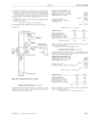
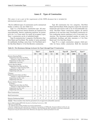
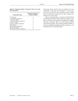
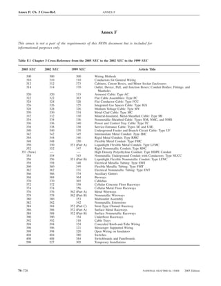
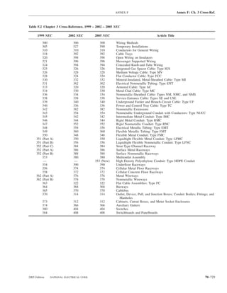
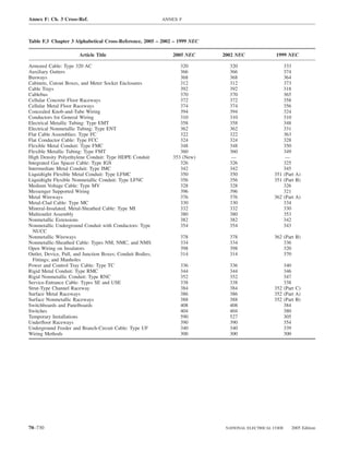
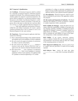
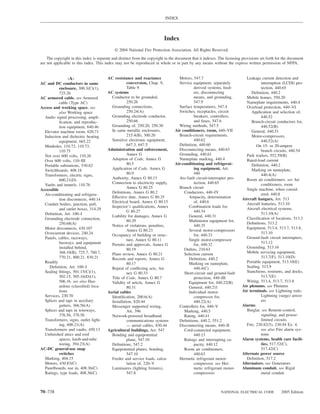
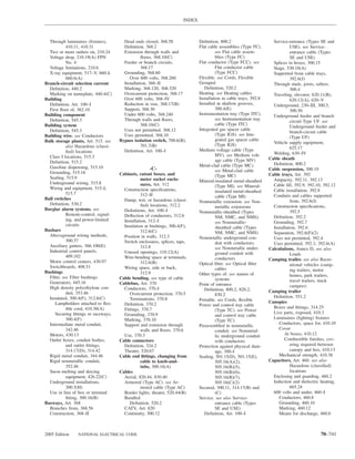
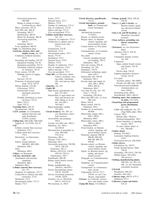
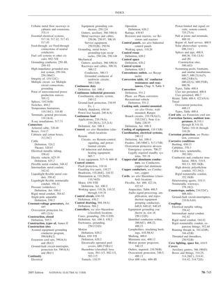
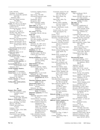
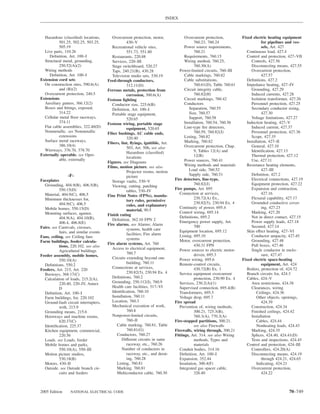
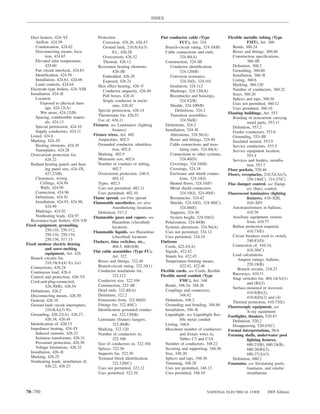
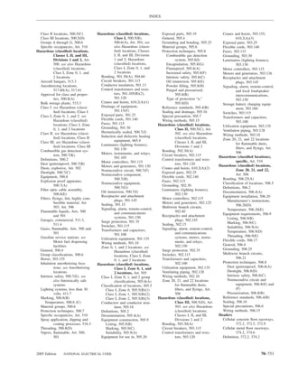
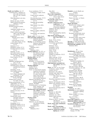
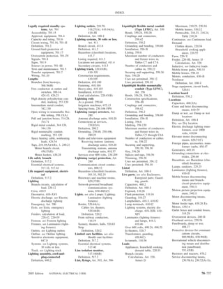
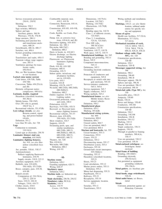
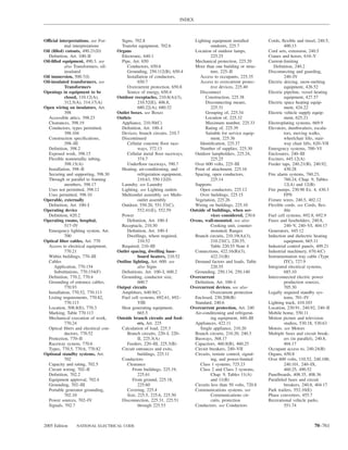
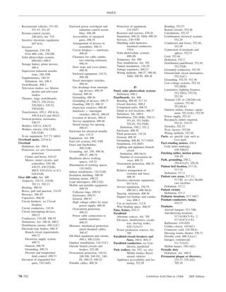
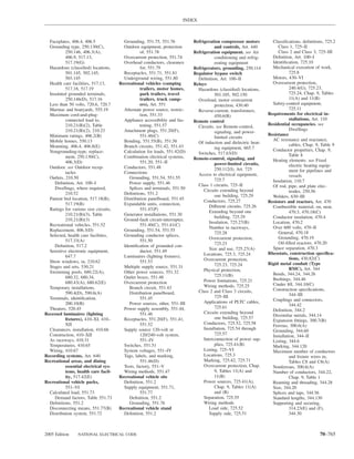
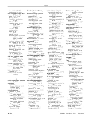
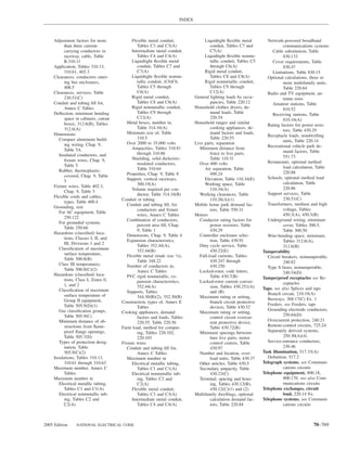
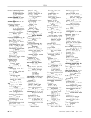
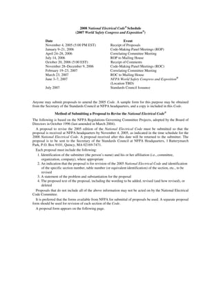
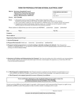


![1) sistemas hidráulicos[1]](https://cdn.slidesharecdn.com/ss_thumbnails/1sistemashidrulicos1-111122190747-phpapp02-thumbnail.jpg?width=640&height=640&fit=bounds)