This document provides guidelines for electrical equipment maintenance. It begins with introductions and copyright information. The document then provides recommendations for maintaining various types of electrical equipment and systems commonly found in industrial and commercial facilities. This includes guidance on maintenance for equipment such as transformers, circuit breakers, batteries, cables, and other electrical components. The recommendations are intended to help reduce electrical hazards and improve safety.


![70B–3COMMITTEE PERSONNEL
Technical Committee on Electrical Equipment Maintenance
Evangelos Stoyas, Chair
U.S. Army Corps of Engineers, VA [U]
Richard P. Bingham, Dranetz-BMI Technologies, NJ [M] Melvin K. Sanders, Things Electrical Co. Inc., IA [U]
Rep. Institute of Electrical and Electronics Engrs. Inc.Edward C. Cantwell, Power Tek Services, Inc., IL [SE]
Harvey C. Grosch, Underwriters Laboratories Inc., IL Robert L. Sandman, Sandman Electric Co., Inc., MA
[IM][RT]
Robert Johnson, Union Carbide Chemicals & Plastics, Rep. Electrical Apparatus Service Assn.
Lynn F. Saunders, GM Worldwide Facilities Group, MITX [U]
Ahto Kivi, U.S. Dept. of State, VA [U] [U]
Thomas E. Smith, North Carolina Dept. of Labor, NCCarl E. Kunkel, Jr., ABB Power T & D Co., Inc., NJ [SE]
Robert J. Lawrie, EC&M Intertec Publishing Corp., NJ [E]
H. Brooke Stauffer, Nat’l Electrical Contractors Assn.,[SE]
Richard R. Lussier, Jr., Northeast Electrical Testing Inc., MD [IM]
John W. Troglia, Edison Electric Inst., WI [U]CT [IM]
Rep. Int’l Electrical Testing Assn., Inc. George K. Waterhouse, State of Colorado, Electrical &
Plumbing Boards, CO [E]Ahmad A. Moshiri, Liebert Global Services, OH [M]
George J. Ockuly, Bussmann, Copper Industries, MO Rep. Int’l Assn. of Electrical Inspectors
Jack Wells, Pass & Seymour Legrand, NY [M][M]
Rep. Nat’l Electrical Mfrs. Assn. Rep. Nat’l Electrical Mfrs. Assn.
John P. Widener, Jr., IBEW, DC [L]Charles R. Prasso, HSB Industrial Risk Insurers, CT [I]
Joseph Patterson Roche´, Acetatet Celanese, SC [M] Rep. Int’l Brotherhood of Electrical Workers
Bruce G. Wyman, Mount Snow Ltd, VT [U]Rep. Chemical Mfrs. Assn.
Alternates
Thomas H. Bishop, Longo Industries, NJ [IM] Michael E. G. Schmidt, Industrial Risk Insurers, CT [I]
(Alt. to R. L. Sandman) (Alt. to C. R. Prasso)
Larry Blake, Northeast Testing of Florida, Inc., FL [IM] James E. Winfrey, Square D Co., NC [M]
(Alt. to R. R. Lussier, Jr.) (Alt. to G. J. Ockuly and J. Wells)
Ronald K. Mundt, U.S. Army Center for Corps of Engr.,
VA [U]
(Alt. to E. Stoyas)
Nonvoting
Albert J. Reed, Macungie, PA
(Member Emeritus)
Joseph V. Sheehan, NFPA Staff Liaison
This list represents the membership at the time the Committee was balloted on the text of this edition. Since that time,
changes in the membership may have occurred. A key to classifications is found at the back of this document.
NOTE: Membership on a committee shall not in and of itself constitute an endorsement of the Association
or any document developed by the committee on which the member serves.
Committee Scope: This Committee shall have primary responsibility for documents on suitable text relating
to preventive maintenance of electrical systems and equipment used in industrial-type applications with
the view of reducing loss of life and property. The purpose is to correlate generally applicable procedures
for preventive maintenance that have broad application to the more common classes of industrial electrical
systems and equipment without duplicating or superseding instructions that manufacturers normally pro-
vide. Reports to the Association through the Correlating Committee of the National Electrical Code
Committee.
1998 Edition](https://image.slidesharecdn.com/nfpa70b1998edition-200219145603/75/Nfpa-70-b-1998-edition-6-2048.jpg)


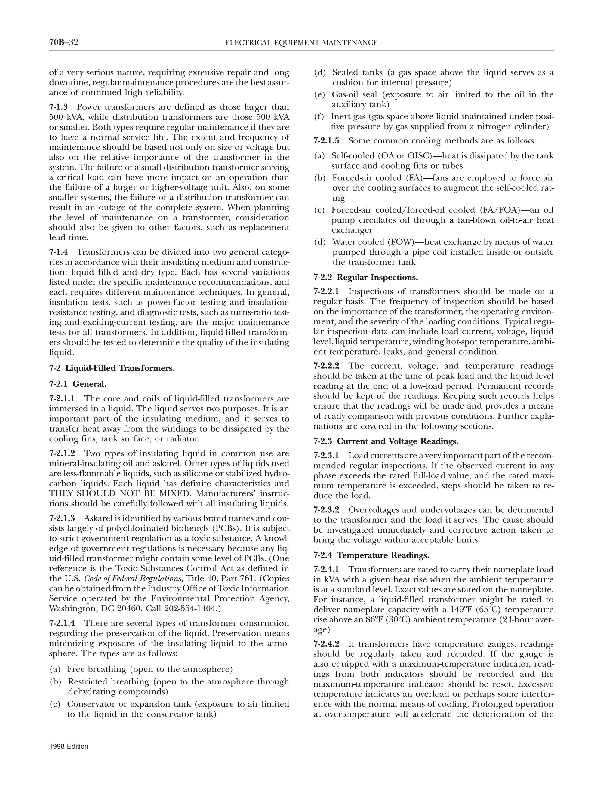
![70B–31POWER AND DISTRIBUTION TRANSFORMERS
The use of an instrument that permits location of such (b) Arc chutes should be removed. Any broken splitter
plates should be replaced.grounds without power outages is recommended.
(c) Main contacts should be inspected. Any heavily frosted6-8.10.4 Maintenance of ground detectors should include a
area should be smoothed with a fine file, stone, crocus cloth,complete inspection of the signal elements such as lamps,
or other suitable abrasive that does not shed abrasive particles.horns, or buzzers. Audible devices should be operated to en-
The hinge joint should be protected from falling particlessure that they are in operable condition. Wiring should be
during dressing.checked for loose connections or damaged wiring.
Summary: A complete, effective maintenance program for (d) During normal operation, arcing contacts become
substations and assembled switchgear will result if the four rough due to arcing. Any especially high projections of metal
‘‘KEEPERS’’ are observed. should be filed smooth.
If it’s insulation, KEEP IT CLEAN and KEEP IT DRY. (e) All electrical connections should be checked to see that
If it’s mechanical, KEEP IT SNUG and KEEP IT FRICTION they are tight.
FREE.
(f) Any abrasion of wire insulation should be observed.
6-8.11 Network Protectors.
(g) Control wire and current-carrying parts should be
6-8.11.1 A network protector is an air circuit breaker checked for overheating.
equipped with specialized relays that sense network circuit (h) All springs should be checked to see that they are in
conditions and command the circuit breaker to either open place and not broken.
or close. There is no separate power source for control. All (i) All nuts, pins, snap rings, and screws should be checked
control power is taken from the system. to see that they are in place and tight.
A routine maintenance schedule for network protectors (j) Any broken barriers should be replaced.
should be observed. Frequency of inspection will vary to a (k) With the rollout unit removed, the following mainte-
great extent on location and environment in which a protector nance operations should be performed inside the enclosure.
is installed.
1. Loose hardware should be looked for on the floor or be-Maintenance should include cleaning any accumulation of
neath the frame. If any is found, it should be traced todust from the unit, a thorough visual inspection, and overall
source.operational test. Should any part look suspicious, the manufac-
turers’ instructions describing operation, adjustment, and re- 2. Stand-off bus insulators should be cleaned.
placement of these parts should be consulted. If relays are 3. Any oxide film should be removed from terminal contacts
out of calibration, they should be recalibrated by competent if necessary.
personnel.
As mentioned above, both network and transformer connec-6-8.11.2 Safety. Network protectors are used where a large
tions should be treated as though they are energized. Whenamount of power is distributed to high-load-density areas. As
working in housing or on frame, use only insulated tools anda result, any short circuit at any point in the system involves
wear safety protective equipment. Do not remove any barriersvery high fault currents. Due to the nature of a secondary
from enclosure.network, some maintenance might be necessary to be per-
formed while the system is energized. In this work, always (l) The protector should be manually closed in accordance
use insulated tools and wear safety gloves. Rigid clearance with the manufacturer’s instructions. It should close with a
procedures must be observed. Extensive use of barriers has definite snap action. Sluggish closing indicates excessive fric-
been a salient feature in the design of this equipment. These tion. The trip level should be moved to ‘‘tripped’’ position.
barriers should be kept in place and any that have been broken The breaker should snap open.
should be replaced immediately. Only skilled maintenance (m) An operational test is best performed using a network
personnel who are thoroughly familiar with the construction protector test kit.
and operation of network protectors should be permitted to
(n) An insulation resistance test, a dielectric test, and elec-perform any maintenance on an energized unit. The first
trical operating tests should be performed strictly in accor-procedure in performing maintenance is to trip the protector
dance with the manufacturers’ recommendations.to the open position.
6-8.11.3 Maintenance. The circuit-breaker mechanism and
relay panel assembly are usually constructed as an integral Chapter 7 Power and Distribution Transformers
draw-out unit that should be withdrawn from the housing
for maintenance. Removal of the fuses at the top and the 7-1 General.
disconnecting links at the bottom (some modern protectors
7-1.1 A transformer is a device for changing energy in anhave bolt-actuated disconnecting fingers at the bottom) iso-
alternating current system from one voltage to another. Itlates the unit electrically from the system. Although this pro-
usually includes two or more insulated coils on an iron core.vides comparative safety, work should be done cautiously since
it might be assumed that normally there is voltage on the 7-1.2 In industrial installations, transformers are usually used
transformer and the network leads. With the draw-out unit to transform or step down a higher distribution level voltage
outside the enclosure on the extension rails, the following to a lower utilization level. They are vital links in electrical
inspection and maintenance operations should be performed power systems and are among the most reliable components
on the draw-out unit. [Item (k) applies only to the containing in the system. If they are not overloaded or otherwise abused,
structure, not the draw-out unit.] they should provide long, trouble-free service. Established
records of reliable performance, coupled with a lack of move-(a) The complete unit should be cleaned. Use of a vacuum-
type cleaner is preferred. Use cloth rags free of oil or greases ment, noise, or other sign of action, often result in general
disregard and neglect. Because a transformer failure is usuallyfor removing clinging dirt.
1998 Edition](https://image.slidesharecdn.com/nfpa70b1998edition-200219145603/75/Nfpa-70-b-1998-edition-34-2048.jpg)
![70B–33POWER AND DISTRIBUTION TRANSFORMERS
liquid and result in reduced life expectancy of the solid ately followed by a test to ensure that the equipment is de-
energized. The equipment should be grounded prior to theinsulation. Either will greatly increase the risk of failure. In
some installations, constant monitoring against overtempera- start of any work. (See Chapter 20.)
ture is provided by special alarm contacts on the temperature
7-2.7.3 All connections should be inspected for signs of over-gauge.
heating and corrosion. Insulators and the insulating surfaces
of bushings should be inspected for tracking, cracks, or7-2.5 Liquid-Level Indicator and Pressure/Vacuum Gauges.
chipped skirts, and the gasketed bases for leaks. The insulating
7-2.5.1 The liquid level should be checked regularly, espe-
surfaces should be cleaned of any surface contamination.
cially after a long period of low load at low ambient tempera-
Damaged insulators or bushings should be replaced. Leaks
ture when the level should be at its lowest point. It is important
should be repaired. Pressure-relief devices should be inspected
that liquid be added before the level falls below the sight glass
to ensure that there are no leaks or corrosion and that the
or bottom reading of the indicator. If a transformer is not
diaphragm or other pressure-relief device is intact and ready
equipped with a liquid-level indicator, the liquid level can be
to function. A cracked or leaking diaphragm should be re-
checked by removing the inspection plate on the top of the
placed at once.
transformer or by removing the top if no inspection plate is
available. The transformer must be de-energized prior to ei- 7-2.7.4 The tank, cooling fins, tubes, radiators, tap changer,
ther of the above two procedures. (See 7-2.7 for precautions and all gasketed or other openings should be inspected for
relative to de-energizing the transformer and for the recommended leaks, deposits of dirt, or corrosion. Leak repair, cleaning, and
procedures for adding liquid.) painting should be done as required. Infrared inspection can
be used to detect fluid levels as well as flow restrictions in7-2.5.2 Pressure/vacuum gauges are commonly found on
cooling tubes.sealed-type transformers and are valuable indicators of the
integrity of the sealed construction. Most sealed transformers 7-2.7.5 The tank ground should be inspected for corrosion
have provisions for adding this device, and, if feasible, it or loose connections. A grounding-electrode resistance test
should be added. The readings should be compared to the should be made, as covered in Section 18-14.
recommendations of the manufacturer as to the normal
7-2.7.6 Cooling fans, circulating oil pumps, and protectiveoperating ranges. High pressures indicate an overload or
relays (for example, Bucholtz relays and sudden-gas relays)internal trouble and should be investigated immediately. A
should be inspected regularly in accordance with manufactur-sustained zero pressure reading indicates a leak or a defective
ers’ recommended practices.gauge.
7-2.7.7 The conservator tank, inert gas atmosphere, and de-7-2.6 Miscellaneous. The features of special types of trans-
hydrating breather equipment should be inspected and testedformer construction that should be included in regular inspec-
according to the manufacturer’s instructions. Since most mod-tions include the following:
ern, large, liquid-filled power transformers have features to
(a) The water-in and water-out temperatures of water-cooled minimize exposure of the liquid to air, opening of this type
transformers of transformer for internal inspection is recommended only
when the need is positively indicated, and then the manufac-(b) The oil-in and oil-out temperatures of forced-oil-cooled
turer’s instructions should be carefully followed or technicaltransformers with oil-to-air or oil-to-water heat ex-
assistance employed.changers
Contamination or impairment of the insulating liquid(c) The pressure in the nitrogen cylinder for a transformer
should be carefully avoided. If the humidity is high, exposureequipped with an automatic gas-pressure system—if the
should be avoided entirely unless the work is absolutely neces-pressure drops below the manufacturer’s recommended
sary and cannot be postponed, in which case special humidity-value [usually about 150 psi (1034 kPa)], the cylinder
control steps should be taken.should be replaced, and leaks repaired
(d) Dehydrating breathers should be checked to ensure that 7-2.7.8 If liquid is to be added, it should be given a dielectric-
they are free from restriction and have not absorbed breakdown test. The liquid to be added should be at least as
excessive moisture warm as the liquid in the transformers. If a large amount of
liquid is added, the transformer should remain de-energized
7-2.7 Special Inspections and Repairs.
for 12 hours or more to permit the escape of entrapped air
bubbles. A desirable method is to add the liquid with the7-2.7.1 Because of the wide variety of liquid-filled trans-
former types, sizes, and uses, as previously listed, the special transformer tank under a vacuum. (Check the manufacturer’s
instructions for further information.)inspection and repair recommendations will be general in
nature. For specific directions, the manufacturer’s recommen-
7-2.8 Liquid Maintenance and Analysis.dations should be followed.
7-2.8.1 Liquid Analysis. For insulating oils, the tests rou-7-2.7.2 If a transformer is given an external visual examina-
tion, the case of the transformer should be regarded as ener- tinely performed are dielectric breakdown, acidity, color,
power factor, interfacial tension, and visual examination.gized until the tank ground connection is inspected and found
to be adequate. If any procedure more extensive than an These tests are covered in Section 18-18. For other insulating
liquids, the manufacturers’ recommendations should be fol-external visual examination is to be performed, the first pre-
caution that should always be observed is to de-energize the lowed.
Tests can also be performed to determine levels of PCBs.transformer. De-energization should always be accompanied
by approved positive lockout or tagout procedures to ensure Test results might require service or replacement of the trans-
former tested as specified by government regulations. (Seeagainst an unplanned re-energization and resulting hazard to
personnel or equipment. De-energization should be immedi- 7-2.1.3.)
1998 Edition](https://image.slidesharecdn.com/nfpa70b1998edition-200219145603/75/Nfpa-70-b-1998-edition-36-2048.jpg)

![70B–35POWER CABLES
might be desirable to periodically replace the gas or recharge should be cleaned. The use of liquid cleaners should be em-
ployed only when it is known that they will not have a deterio-the transformer instead of locating and sealing the leak. The
replacement gas should be either the same as the original or rating effect on the insulation.
an approved substitute. (See 7-3.7 for recommendations covering 7-3.7.4 Best service life will result if the windings are main-
severe leaks.) tained above the ambient-temperature level. For this reason,
7-3.5.2 High pressures are an indication of electrical over- transformers operating in high humidity should be kept ener-
load or internal trouble. They should be immediately investi- gized, if feasible. If a transformer is to be de-energized long
gated and corrective action should be taken. Excessive enough for it to cool, special drying procedures might be
pressure can result in distortion or rupture of the tank. necessary before the transformer is re-energized. Refer to the
manufacturers’ recommendations for drying procedures to7-3.6 Miscellaneous. The louvers in the enclosures of venti-
be followed.lated dry-type transformers should be inspected to see that
7-3.7.5 Sealing severe leaks or opening and resealing thethey are not clogged with dirt or otherwise obstructed. Also,
tanks of sealed dry-type transformers requires special proce-the operation of integral ventilating fans should be checked.
dures and equipment. The manufacturer of the transformer,Dry-type transformers are usually installed indoors and some-
an experienced transformer repair facility, or a qualified elec-times in a vault. The temperature of the vault or room should
trical maintenance contractor should perform this work.be measured regularly and recorded. Proper ventilation is
In addition, special procedures covering drying out of theessential to the operation of a transformer. Any material or
windings, plus purging and refilling of the tank, might beobstruction that might prevent the free circulation of air
necessary.around a transformer should be removed. If the room or vault
has power-driven ventilating fans, their correct operation [air 7-3.8 Insulation Tests. The insulation tests covered in 7-2.9.1
velocity should not exceed 400 ft/min (122 m/min)] should and 7-2.9.2 can also be applied to dry-type transformers.
be determined and overtemperature alarms, if provided,
should be tested. Corrosion of the transformer enclosure, the
intrusion of dirt, as well as evidence of water leaks into the Chapter 8 Power Cables
room or vault, should also be carefully checked and corrective
measures taken as required. A high noise level or change in 8-1 General. Preventive maintenance is the best way to en-
level could indicate improper installation or loose windings sure continued reliable service from electrical cable installa-
or barriers. tions. Visual inspection and electrical testing of the insulation
are the major maintenance procedures. However, it should be7-3.7 Special Inspections and Repairs.
stressed that no amount of maintenance can correct improper7-3.7.1 When a transformer is given an external visual exami-
application or physical damage done during installation.nation, the transformer case should be regarded as energized
until the case-ground connection is inspected and found to 8-2 Visual Inspection.
be adequate. If any procedure more extensive than an external 8-2.1 If, in addition to the visual inspection, cables are to be
visual examination is to be performed, the first precaution touched or moved, they should be de-energized.
that should always be observed is to de-energize the trans-
8-2.2 Cables in manholes should be inspected for sharpformer. De-energization should be accompanied by approved
bends, physical damage, excessive tension, oil leaks, pits, cablepositive lockout procedures to ensure against an unplanned
movement, insulation swelling, soft spots, cracked jackets inre-energization and resulting hazard to personnel or equip-
nonlead cables, damaged fireproofing, poor ground connec-ment. De-energization should be immediately followed by a
tions, deterioration of metallic sheath bonding, as well astest to ensure that the equipment is de-energized. The equip-
corroded and weakened cable supports and the continuityment should be grounded prior to the start of any work. (See
of any main grounding system. Terminations and splices ofChapter 20.)
nonlead cables should be squeezed in search of soft spots and
7-3.7.2 Enclosure covers of ventilated dry-type transformers inspected for tracking or signs of corona. The ground braid
should be removed carefully. An inspection for the following should be inspected for corrosion and tight connections. In-
problems should be made: spect the bottom surface of the cable for wear or scraping,
due to movement, at the point of entrance into the manhole(a) Accumulations of dirt on windings, insulators, and where
cooling airflow might be restricted and also where it rests on the cable supports.
(b) Discoloration caused by overheating 8-2.3 Inspect the manhole itself for spalling concrete or dete-
(c) Tracking and carbonization rioration of the above-ground portion. In some instances, the
manhole can be equipped with drains, and these might re-(d) Cracked or chipped insulators
quire cleaning; in some instances, it might be necessary to(e) Loose insulators, clamps, or coil spacers
pump water from the manhole prior to entrance. Do not enter
(f) Deterioration of barriers
a manhole unless a test for dangerous gas has been made and
(g) Corroded or loose electrical connections. adequate ventilation is provided. The inspection crew should
always consist of two or more persons with at least one re-In addition, the equipment ground should be inspected
maining outside of the manhole. (See OSHA 29 CFR, Partfor corrosion or loose connections. A grounding-electrode
1910.146, for confined space entry and Part 7 1910.269(e) forresistance test should be made as covered in Section 18-14.
enclosed space entry.)7-3.7.3 Dirt and dust should be cleaned from the windings
with a vacuum cleaner. After vacuum cleaning, compressed 8-2.4 Potheads should be inspected for oil or compound
leaks and cracked or chipped porcelain. The porcelain sur-air can be used, only if it is clean and dry and applied at
a low pressure to avoid damage to windings. In particular, faces should be cleaned and, if the connections are exposed,
their tightness should be checked.ventilating ducts and the top and bottom of the windings
1998 Edition](https://image.slidesharecdn.com/nfpa70b1998edition-200219145603/75/Nfpa-70-b-1998-edition-38-2048.jpg)


![70B–58 ELECTRICAL EQUIPMENT MAINTENANCE
18-20.2 Dielectric-Absorption Testing. A more complete
and preferred test applies the voltage for 10 minutes or more
to develop the dielectric-absorption characteristic. The curve
obtained by plotting insulation resistance against time gives
a good indication of moist or dirty windings. A steady rising
curve is indicative of a clean, dry winding. A quickly flattening
curve is the result of leakage current through or over the
surface of the winding and is indicative of a moist or dirty
winding. If facilities are not available for a 10-minute test,
readings can be taken at 30 and 60 seconds. The ratio of the
60-to-30-second or the 10-to-1-minute ratio will serve as an
indication of the winding condition. The following table
should serve as a guide in interpreting these ratios.
Condition 60:30-Second Ratio 10:1-Minute Ratio
100
80
60
40
20
0
0 5 10 15 20 25 30 35 Kilovolts
Maximum
test
voltage
A
C
B
d
c
b
a
Microamperes
Breakdown
Dangerous — Less than 1
Figure 18-20.3.3 High-potential test.
Poor Less than 1.1 Less than 1.5
Questionable 1.1 to 1.25 1.5 to 2
Fair 1.25 to 1.4 2 to 3 breakdown (point c in Figure 18-20.3.3)] does not occur below
the maximum required test voltage, and as long as the shapeGood 1.4 to 1.6 3 to 4
of the curve is not too steep compared with that of similarExcellent Above 1.6 Above 4
equipment or prior test of the same equipment, the results
can be considered satisfactory. It should be recognized that
if the windings are clean and dry, overvoltage tests will not18-20.3 Over-Potential Testing.
detect any defects in the end turns or in lead-in wire located
18-20.3.1 Overvoltage tests are performed during normal away from the stator iron.
maintenance operations or after servicing or repair of im-
18-20.4 Surge-Comparison Testing.portant machines. Such tests, made on all or parts of the
circuit to ground, ensure that the insulation level is sufficiently 18-20.4.1 Surge-comparison testing can detect turn-to-turn,
high for continued safe operation. Both ac and dc test equip- coil-to-coil, group-to-group, and phase-to-phase winding flaws
ment are available. There is no conclusive evidence that one that cannot be detected by insulation-resistance, dielectric-
method is preferred over the other. However, where equip- absorption, or over-potential testing. Surge testing should not
ment using several insulating materials is tested, ac stresses be undertaken until after the integrity of insulation to ground
the insulation more nearly to actual operating conditions than has been verified.
dc. Also, more comparable data have been accumulated since
18-20.4.2 The surge testing principle is based on the premiseac testing has had a head start. However, the use of dc has
that the impedances of all 3-phase windings of a 3-phase ma-several advantages and is rapidly gaining favor with increased
chine should be identical if there are no winding flaws. Eachusage. The test equipment is much smaller, lighter in weight,
phase (A/B, B/C, C/A) is tested against the others to deter-and lower in price. There is far less possibility of damage to
mine if there is a discrepancy in winding impedances.equipment under test, and dc tests give more information
than is obtainable with ac testing. 18-20.4.3 The test instrument imposes identical, high-volt-
age, high-frequency pulses across two phases of the machine.18-20.3.2 The test overvoltages that should be applied will
The reflected decay voltages of the two windings are displayeddepend on the type of machine involved and level of reliability
and captured on an oscilloscope screen. If the winding imped-required from the machines. However, it should be of suffi-
ances are identical, the reflected decay voltage signatures willcient magnitude to search out weaknesses in the insulation
coincide and appear on the screen as a single trace. Twothat might cause failure. Standard over-potential test voltage
dissimilar traces indicate dissimilar impedances and a possiblewhen new is twice rated voltage plus 1000 volts ac. On older
winding flaw. (See Figure 18-20.4.3.)or repaired apparatus, tests are reduced to approximately 50
to 60 percent of the factory (new) test voltage. (See ANSI/IEEE 18-20.4.4 The testing and interpretation of results should be
4, Standard Techniques for High Voltage Testing.) For dc tests, the conducted by a trained individual.
ac test voltage is multiplied by a factor (1.7) to represent the
18-20.5 Other Tests. There are several other types of tests,ratio between the direct test voltage and alternating RMS
depending on the need and desired results listed below. Thesevoltage. (See ANSI/IEEE 95, Recommended Practice for Insulation
more complex tests, however, are not employed unless appara-Testing of Large AC Rotating Machinery with High Direct Voltage.)
tus performance indicates these tests should be made and
18-20.3.3 A high-potential test made to determine the condi- experienced testers are available with the test equipment.
tion of the insulation up to a predetermined voltage level is
(a) Turn-to-turn insulationdifficult to interpret. It is common practice to compare known
good results against test specimens to determine what is ac- (b) Slot discharge and corona
ceptable and what fails the test. For a dc high-potential test,
(c) Winding impedance test
the shape of the leakage current plotted against voltage rise
(d) Power-factor valueis an additional used criteria.
As long as the knee of the curve [which indicates impending (e) Core loss test
1998 Edition](https://image.slidesharecdn.com/nfpa70b1998edition-200219145603/75/Nfpa-70-b-1998-edition-61-2048.jpg)


![70B–84 ELECTRICAL EQUIPMENT MAINTENANCE
24-4.4.5 Monitoring Instrument Sensitivity. Power monitor-dents can result in voltage sags. Such faults can be 3-phase,
line-to-line or line-to-ground. The 3-phase faults are the most ing instruments are quite sensitive, and outside factors can
influence their accuracy. Long measurement leads are suscep-severe, but are relatively uncommon. Single line-to-ground
faults on the utility system are a common cause of voltage sags tible to RFI/EMI pickup, which can distort the results.
in an industrial plant. A fault on a single feeder can result in
24-4.5 Solutions for Sags and Swells.
an interruption to loads on that feeder, as well as a sag on
24-4.5.1 A transformer tap change can be used to raise orthe other feeders.
lower the nominal voltage level and make the system less
24-4.3.2.2 Sag Duration. Typically, distribution system sags susceptible to sags or swells. Automatic solid state tap-changing
are 6–20 cycles. Repeated sags can occur when reclosing on transformers that are controlled by electronic sensing circuits
the same fault. Depending on the number of reclosures, feed- can react relatively quickly (1–3 cycle).
ers can experience several voltage sags in succession.
24-4.5.2 Different transformer configurations can be used
24-4.3.3 Sag Causes—Facility Power Systems. to minimize the effects of events that cause sags and swells.
For example, a delta-delta configuration tends to hold voltage24-4.3.3.1 Sudden increases in the current demand within
levels higher than a delta-wye or a wye-delta configuration.a facility can cause sags until the large current demand de-
creases. The sudden increases can be the result of fault condi- 24-4.5.3 Fault current limiters, zero voltage independent
tions within the building, or the start up of large inductive pole closing capacitor switches, and high-energy surge arrest-
loads, such as motors. In one large scale study (see Section 24- ers can be added to the electric system.
10), 50 percent or more of the sags and swells recorded were 24-4.5.4 Ferroresonant transformers, also called constant-
caused by load equipment in the same building. voltage transformers, can handle most short duration voltage
sags. They provide excellent regulation, but have limited over-24-4.3.3.2 A voltage sag can last for 30 cycles for large, high
load capacity and poor efficiency at low loads.current demand motors.
24-4.5.5 Magnetic controlled voltage regulators use trans-24-4.3.3.3 A utility fault usually creates a more severe sag
formers, inductors, and capacitors to synthesize 3-phase volt-than a motor start sag. The sag will last until the fault is cleared
age outputs. Enough energy is stored in the capacitors to rideor removed.
through one cycle. The overall response time is relatively slow
24-4.3.4 Swell Causes. (3–10 cycles).
24-4.3.4.1 Swells are less common than voltage sags, and are 24-4.5.6 A UPS can provide isolation from power line distur-
usually associated with system fault conditions. A swell can bances, in addition to providing ride-through during an sag.
occur due to a single line-to-ground fault on the system, which (See Chapter 22.)
can result in a temporary voltage rise on the unfaulted phases.
24-4.5.7 A static transfer switch is capable of transferring the
24-4.3.4.2 Swells can also be generated by sudden load de- supply voltage from one voltage source to another within a
creases. The abrupt interruption of current can generate a quarter-cycle.
large voltage, proportional to the inductance and the rate of
24-5 Long Duration Undervoltages and Sustained Voltagechange of the current. Switching on a large capacitor bank
Interruptions.can also cause a swell, though it more often causes a high
frequency transient. 24-5.1 Normal Supply Voltage Variations. Variations in the
normal supply voltage are to be expected because loads on the24-4.4 Monitoring and Testing for Sags and Swells.
supply system and plant distribution system are not constant.
24-4.4.1 Different types of monitoring equipment are avail- Electric utilities, equipment manufacturers, and end users
able to monitor sags and swells. These range from event indica- have established standards for steady state operating voltage
tors that visually indicate that a sag or swell has occurred, to limits that accommodate these variations. Facility utilization
graphical monitors that provide a cycle-by-cycle picture of equipment can be designed and rated to operate within the
the disturbance and record the minimum/maximum values, range of supply system voltage while allowing for voltage drop
duration, and time of occurrence. in the plant system. [See ANSI/NEMA C84.1, Electric Power Sys-
tems and Equipment, Voltage Ratings (60 Hertz).]
24-4.4.2 Finding the Source. Data on the timing and magni-
tude of the sag or swell can often identify the source of the 24-5.1.1 Electric Utilities. Electric utilities can be required
by their regulatory commissions to maintain service voltagesinitiating condition. If the phase current levels of the load
did not change prior to the voltage sag, the source is more within prescribed limits for the various types of service. Plant
electrical people should be aware of any required service volt-likely to be upstream. When the magnitude of the sag is severe,
it is likely that the source was close by. A power-factor correc- age limits for their type of service. The utility generally works
with the customer to ensure that the service voltage remainstion capacitor being switched on can result in an oscillatory
transient followed by a swell. within the required limitations or within their standard design
limits where there are no required limitations.
24-4.4.3 Unless there is significant information pointing to
As the system load varies, the utility automatic voltage regu-
the source of the disturbance, it is common practice to begin
lating equipment maintains the service voltage within the re-
monitoring at the point where the utility service connects to
quired range. When the serving utility’s electrical system is
the facility equipment.
severely stressed, the utility can implement a load reduction
strategy by reducing the voltage on its distribution lines, typi-24-4.4.4 If the source of the disturbance is determined to
be internal to the facility, then placing multiple monitors on cally up to 5 percent. During these periods, the service voltage
can be near the lower limit of the required range. As a result, athe various circuits within the facility would most likely identify
the source of the problem quickly. long-term undervoltage condition can exist at plant utilization
1998 Edition](https://image.slidesharecdn.com/nfpa70b1998edition-200219145603/75/Nfpa-70-b-1998-edition-87-2048.jpg)
![70B–85POWER QUALITY
equipment. It is important to keep plant distribution system Single phasing, which is the complete loss of a phase, is the
worst-case voltage unbalance condition for a 3-phase circuit.voltage drops to a reasonable level.
24-5.2 Definition of Long Duration Undervoltage. A long 24-6.1.1 Percentage Limitations. The National Electrical
duration undervoltage is a decrease of the supply voltage to Manufacturers Association (NEMA) in its Motors and Genera-
less than 90 percent of the nominal voltage for a time duration tors Standards (MG1) part 14.35, defines voltage unbalance
greater than 1 minute. [See ANSI/NEMA C84.1, Electric Power as follows:
Systems and Equipment, Voltage Ratings (60 Hertz).]
percent unbalance ס 100 ן (maximum voltage deviation24-5.3 Symptoms of Long Duration Undervoltage. Un-
from the average voltage) divided by the average voltage.dervoltage might not be readily apparent. Depending on the
length and magnitude of the undervoltage, there can be a NEMA states that polyphase motors shall operate success-
detrimental effect on electrical and electronic equipment. fully under running conditions at rated load when the voltage
Equipment such as induction motors might run hotter. Elec- unbalance at the motor terminals does not exceed 1 percent.
tronic equipment such as computers or microprocessor based Also, operation of a motor with more than 5 percent unbal-
devices can function erratically. ance condition is not recommended, and will probably result
in damage to the motor.24-5.4 Causes of Long Duration Undervoltage. A long dura-
Example: With line-to-line voltages of 460, 467, and 450,tion undervoltage can originate on the electric utility system
the average is 459, the maximum deviation from average is 9,or on the plant electrical system. The utility system can be
and the percent unbalance equals 100 ן (9/459) ס 1.96stressed due to line or equipment failure or system load condi-
percent, which exceeds the 1 percent limit.tions exceeding the supply capability. The plant electrical sys-
tem or connected loads can result in unacceptable voltage
24-6.2 Causes of Unbalanced Voltages.drops even though the voltage is normal at the service point.
24-6.2.1 Unbalanced voltages usually occur because of varia-24-5.5 Monitoring and Testing of Long Duration Under-
tions in the load. When phases are unequally loaded, unbal-voltages. Because the occurrence of a long duration under-
anced voltages will result because of different impedances.voltage might not be obvious and damage to equipment and
systems can result, an appropriate monitoring system is recom- 24-6.2.2 Symptoms and causes of unbalanced voltages in-
mended where reliability is vital. clude the following:
The monitoring system can consist of a sophisticated warn-
ing scheme with visual and audible alarms at appropriate (a) Unequal impedance in conductors of power supply wiring
locations. Alternatively, it can simply be a voltage sensing relay
(b) Unbalanced distribution of single-phase loads such aslocated at the facility service entrance or at sensitive equip-
lightingment with alarms placed in appropriate locations.
(c) Heavy reactive single-phase loads such as welders
24-5.6 Solutions for Long Duration Undervoltages. When a
(d) Unbalanced incoming utility supplylong duration undervoltage occurs, costly and/or sensitive
equipment should be disconnected to prevent possible dam- (e) Unequal transformer tap settings
age. If the equipment or system must be kept in operation, (f) Large single-phase load on the system
then an alternative power supply should be provided.
(g) Open phase on the primary of a 3-phase transformer
24-5.7 Definition of a Sustained Voltage Interruption. A sus-
(h) Open delta connected transformer banks
tained voltage interruption is the loss of the supply voltage
(i) A blown fuse on a 3-phase bank of power factor correctionto less than 10 percent on one or more phases for a period
capacitorsgreater than 1 minute.
24-5.8 Symptoms of a Sustained Voltage Interruption. A sus- 24-6.3 Symptoms.
tained voltage interruption is obvious because electric power
24-6.3.1 The most common symptoms of unbalanced volt-is unavailable for an extended period of time except for equip-
ages are improper operation of, or damage to, electric motors,ment served by an alternate power source.
power supply wiring, transformers, and generators.
24-5.9 Causes of Sustained Voltage Interruption. Sustained
24-6.3.2 Unbalanced voltages at motor terminals can causevoltage interruptions are caused by power system disruptions
phase current unbalance to range from 6 to 10 times thesuch as power lines going down in a storm, the utility’s distribu-
voltage unbalance for a fully loaded motor. As an example, iftion transformer failing, a fault condition causing a circuit
a voltage unbalance is 2 percent, then current unbalanceprotective device to open, or plant wiring problems.
could be anywhere from 12 percent to 20 percent. This causes
24-5.10 Solutions for Sustained Voltage Interruptions. Solu- motor overcurrent, resulting in excessive heat that shortens
tions include generator sets, multiple power sources, and bat- motor life.
tery banks. The unbalance at the motor terminals will cause speed and
torque to be reduced. If the voltage unbalance is great enough,24-6 Unbalanced Voltages and Single-Phasing.
the reduced torque capability might not be adequate for the
24-6.1 Definition of Unbalanced Voltages. Unbalanced volt- application. Noise and vibration levels can also increase as a
ages are unequal voltage values on 3-phase circuits that can result of voltage unbalance.
exist anywhere on the power distribution system. On 3-phase
circuits, however, unbalanced voltages can cause serious prob- 24-6.3.3 Motor Heating and Losses. Insulation life is ap-
proximately halved for every 18ЊF (10ЊC) increase in windinglems, particularly to motors, transformers, and other inductive
devices. temperature. The following table illustrates the typical per-
1998 Edition](https://image.slidesharecdn.com/nfpa70b1998edition-200219145603/75/Nfpa-70-b-1998-edition-88-2048.jpg)

![70B–87POWER QUALITY
24-7.2.3 Ground loops are undesirable because they create common mode noise is seen equally and in phase between
any phase conductor or neutral and the grounding conductor.a path for noise currents to flow.
Neutral-to-ground voltage or ground current can be a result
24-7.3 Monitoring and Testing—Grounding. The electrical
of common mode noise.
connection to earth can be measured using the three-point
system referred to the ANSI/IEEE 142, Recommended Practice 24-8.1.2 Transverse Mode Noise. Transverse mode noise is
for Grounding of Industrial and Commercial Power Systems (Green sometimes referred to as normal or differential mode noise.
Book). It is desirable to minimize the impedance between the It is undesirable electrical signals that exist between a pair of
equipment grounded conductor and the grounding conduc- circuit conductors. In a 3-phase system, transverse mode noise
tor. occurs in phase on all 3-phase conductors and neutral.
(a) A visual inspection should be made to verify the integrity 24-8.1.3 Interference. Interference that is electromagneti-
of the grounding and bonding conductors and associated cally coupled into a wiring system is called electromagnetic
connections. interference (EMI). Interference that is capacitively coupled
into a wiring system is called radio frequency interference(b) An impedance test should be performed on the equip-
(RFI). Interference can appear as transverse or common modement grounding conductor.
noise.(c) Voltage should be measured between the equipment
grounding conductor and the grounded conductor. 24-8.2 Symptoms.
(d) A check should be made for abnormal currents on the
24-8.2.1 Electrical noise is present in all circuits to a certainequipment grounding conductor.
degree. It might or might not present a problem. Unlike sags
24-7.4 Solutions—Grounding. or swells, electrical noise usually does not normally destroy
equipment. It does not cause circuit breakers to trip, unless24-7.4.1 The grounded conductor should be connected to
the noise affects shunt trip or undervoltage release controls.the equipment grounding conductor only as permitted by
NFPA 70. 24-8.2.2 Electrical noise usually manifests itself in the form of
data corruption and/or unexplained equipment malfunction.24-7.4.2 Isolated Equipment Ground. One solution is to in-
For example, electrical noise can create ‘‘hum’’ in a telephonestall an ‘‘isolated ground’’ receptacle (identified by orange
system, ‘‘snow’’ on a video image, or cause a computer to lockcolor or an orange triangle) in which the equipment ground-
up.ing terminal is insulated from the mounting strap. An insu-
lated equipment grounding conductor is then connected from 24-8.3 Causes. Electrical noise is a byproduct of the normal
the grounding terminal of the receptacle in accordance with operation of electrical equipment. The type and sources of
National Electrical Code, Article 250. The insulated equipment noise are as diverse and numerous as the number of facilities
grounding conductor is connected to the applicable derived that contain power systems.
system or service grounding terminal only at the power source.
(a) Transformers generate magnetic fields that can influence
24-7.4.3 Isolation Transformer. An isolation transformer adjacent pieces of equipment.
has separate primary and secondary windings with an in-
(b) Long cable runs between interconnected pieces of com-terwinding shield that has its own grounding connection. The
puter equipment can act as an antenna to a local radiobonding jumper between the equipment grounding conduc-
station.tor and the secondary grounded conductor provides protec-
(c) Any piece of electronic equipment that contains a switchtion from common mode electrical noise.
mode power supply will introduce electrical noise to some
24-7.4.4 Signal Circuit Isolation. Breaking the ground loop degree into both the building wiring system, as well as
current path will minimize ground currents on signal circuits. the air.
This can be accomplished by one or more of the following:
(d) Poor electrical wiring connections can create electrical
noise. A loose connection can vibrate, creating an arc at(a) Grounding at a single point per system [See ANSI/IEEE
the connection, resulting in noise.142, Recommended Practice for Grounding of Industrial and
Commercial Power Systems (Green Book)]
24-8.4 Monitoring and Testing. Locating the sources, fre-
(b) Fiber optic transmission over completely nonconducting quency, and amplitude of noise can be a difficult and time-
path consuming task. Troubleshooting becomes increasingly
(c) Optical isolators difficult as multiple sources of noise might be present. De-
termining the amplitude and frequency of the noise signal is(d) Signal circuit isolation transformers in signal circuit or
essential in identifying the source. Typically, several differentpower circuits
types of test equipment can be required to isolate the nature
24-8 Noise in Electrical and Electronic Systems. of the noise. These include the following:
24-8.1 Definition. Noise is undesirable electrical signals in
(a) Spectrum analyzer—capable of measuring a wide range
an electrical or electronic circuit. It can be random or continu-
of frequencies
ous in nature. Noise can occur at any frequency and amplitude.
(b) Conducted RFI/EMI recorder—capable of measuringNoise can be introduced into a circuit from a multitude of
noise levels superimposed on the voltage waveformsources, and manifest itself in equipment malfunction or data
corruption. (c) Radiated RFI/EMI recorder—capable of measuring elec-
trical noise levels present in the air
24-8.1.1 Common Mode Noise. Common mode noise is un-
(d) Digital storage oscilloscope with line decouplerdesirable electrical signals that exist between a circuit conduc-
tor and the grounding conductor. In a 3-phase system, (e) Power quality monitor
1998 Edition](https://image.slidesharecdn.com/nfpa70b1998edition-200219145603/75/Nfpa-70-b-1998-edition-90-2048.jpg)


![70B–122 ELECTRICAL EQUIPMENT MAINTENANCE
Table H-2(a) Medium Voltage Equipment, Cables, Terminations, and Connections; Maintenance of Equipment Subject to Long Intervals Between
Shutdowns—Electrical Distribution, Continued
Type Inspections, Maintenance, and Tests Typical Frequency and Remarks
Clean and inspect stress cones and leakage For soundness of stress cones.
sections (8-2.3) (6-2.13). X-ray or disassemble, if soft spots are detected.
For surface tracking.
Check plastic jackets for longitudinal Jacket shrinkage might have damaged
shrinkage from splices and terminations. shielding tapes or stress cones.
Check integrity of shield grounding (8-2.3). Observe ground connections for stress cones.
Suggest checking electrical continuity of
shielding tape.
Check general condition of cable (8-2.3). Does insulating material appear to have been
damaged by overheating?
Observe connectors for overheating (8-2.5) Discoloration and/or oxidation indicate
(6-1.3) (6-2.14). possible problem.
Check bolts for tightness, if accessible. If
connectors are insulated with tape,
deterioration or charring of tape is
indicative of overheated connector, caused
by loose bolts, etc.
Infrared survey while conductors are
energized and loaded to at least 40 percent
of ampacity may be beneficial to detect
overheated connections. Use good quality
infrared scanning equipment.
Test cable insulation with high potential dc Disconnect cables from equipment and
(8-5) (18-9.1). provide corona protection on ends. Ground
other conductors not being tested.
Record leakage current in microamperes at
each test voltage level.
Record temperature and relative humidity.
Determine condition of cable insulation Interpret test results, considering length of
[18-9.2.4.3(a)3 ]. cable, number of taps, shape of megohm or
leakage current curve, temperature and
relative humidity.
Reconnect cables to equipment Tighten connectors adequately.
Aluminum conductors. Make certain that connectors of the proper
type are correctly installed.
Use Belleville washers when bolting aluminum
cable lugs to equipment.
Advisable to determine conductivity of
connection using microhmmeter or
determine voltage drop under test load
conditions
(18-12).
1998 Edition](https://image.slidesharecdn.com/nfpa70b1998edition-200219145603/75/Nfpa-70-b-1998-edition-125-2048.jpg)


![70B–133APPENDIX H
Table H-2(e) Medium Voltage Equipment, Circuit Breakers; Maintenance of Equipment Subject to Long Intervals Between Shutdowns—Electrical
Distribution, Continued
Type Inspections, Maintenance, and Tests Typical Frequency and Remarks
Insulating oil (6-6.2.2 through 6-6.2.4) (18-17) For level, general condition, dielectric
(7-2.8). strength, and acidity.
Make necessary repairs.
Testing (withdrawn from switchgear and de- Max. of three years, etc., same as above block.
energized) (5-3) (18-5 through 18-8):
Insulation (18-9.1) (18-9.2.1) (18-9.2.2) High-potential test each main contact with
[18-9.2.4(a)]. breaker open and all other main contacts
and frame grounded. Use 1000 volt
insulation resistance tester on auxiliary
devices and controls and associated wiring.
Test oil for dielectric strength. Clean tank and
breaker mechanism. Filter oil or replace as
required (6-6.2.4).
Contact conductivity or resistance (18-12). Use microhmmeter or determine voltage drop
under test load conditions.
dc high-potential and/or power-factor test Record results.
(18-9.1) (18-9.2) (18-9.3.2).
Overcurrent trip devices (electromechanical Pass specified currents from current test set
type) on breakers so equipped (6-4.6.4). through coils of trip devices to open breaker
contacts within time limits accord ing to
manufacturer’s or specially designed time-
current coordination curves.
Adjust trip devices as required to accomplish
desired results.
Test set should be equipped with cycle counter
for accuracy of instantaneous trip tests.
Record results.
System Testing (breaker installed):
Electrically operated breaker. After above maintenance has been
satisfactorily completed, connect electrically
operated breaker to switchgear or test stand
control wiring by means of the test cord and
plug.
Operate closing control devices to assure that
breaker closes and latches without trip-free
operations.
Operate trip control devices to assure that
breaker trips open in a reliable manner
(6-4.6.3).
Functionally test all electrical interlock and
safety devices.
After satisfactorily passing all operational tests,
the breaker may be placed in its switchgear
cell and be racked into the ‘‘CONNECTED’’
position, and placed in normal service.
Air-break and Oil-immersed, Fixed Type Maintenance and Testing: Same frequencies as similar drawout type
(6-4.1.2) Open all disconnect switches to isolate main breaker preceding.
contacts from electrical supply and load Use adequate safety procedures.
wiring (5-3). Verify that no parts of the
power or control circuitry are energized by
1998 Edition](https://image.slidesharecdn.com/nfpa70b1998edition-200219145603/75/Nfpa-70-b-1998-edition-136-2048.jpg)


![Ebc codes[1]](https://cdn.slidesharecdn.com/ss_thumbnails/ebccodes1-140206134542-phpapp01-thumbnail.jpg?width=640&height=640&fit=bounds)


