This document provides information about the National Board Inspection Code for 2011, including its various committees and subgroups that were involved in developing the code. It lists the members of these committees and subgroups, which include representatives from government regulatory agencies, insurance companies, manufacturers, and others. The document also provides contact information for the National Board headquarters and other facilities.


![201 1 INATIONAL. BCARC I NSPECTION CODE
b) Organizations desiring to renew or obtain a National Board Certificate ofAuthorization shall apply to the
National Board using fonns obtained from the National Board.Application for renewal shall be made prior
to the expiration date of the Ceroficate ofAuthorization.
c) When an organization has plants or shops in morethan one location, the organization shall submit sepa-
rate applications for each plant or shop. The organization may perform repairs or alterations in its plants.
shops, or in the field, provided such operations are described in the organization's Quality System.
d) Upon notification ofthe review dates from the National Board, it is the responsibility ofthe organization to
make arrangements for the review.
e) The Review Team, as a minimum. shall consist of one representative each from the Authorized Inspection
Agency and the Jurisdiction.'
f) The Review Team shall conduct an evaluation ofthe organization's Quality System. The organization shall
demonstrate sufficient implementation of the Quality System to provide evidence of the organization's
knowledge ofwelding, nondestructive examination,postweld heattreatment, and other repair or a~eration
activities performed appropriate for the requested scope ofwork. The demonstration shall be performed
using current work, a demonstration mock-up, or a combination of both.
g) A recommendation to issue, renew, or withhold t~e National Board Certificate ofAuthorization shall be
included in a Review Report prepared by the Review Team. The completed Review Report shall be for-
.· warded to the National Board.
.;
li) If proper administrative fees are paid and all other requirements are met, a Certificate ofAuthorization will
be issued evidencing permission to use the "R" Symbol Stamp. The certificate shall expire on the triennial
:: anniversary date.
i) When an organization holding a National Board Certificate ofAuthorization changes ownership, name,
location, or address, the National Board shall be notified. The Certificate ofAuthorization may be revised
by submitting an application for National Board "R" Certificate ofAuthorization; however, are-review may
be required.
j) The holder of an ASME Code Symbol Stamp, whose facilities were reviewed (with the exception of "V,"
"UV," "HV," "NV," and "H" [cast iron or cast aluminum]) may obtain National Board authorization without a
review of its facilities, provided:
1) The organization has a Quality System to cover the scope of the repairs or alterations to be made,
subject to review by the Jurisdiction; and
2) The application for the "R" Certificate ofAuthorization is submitted within 12months from the issuance
oftheASME Certificate ofAuthorization. The initial Certificate ofAuthorization shall be issued to expire
concurrent with theASME Certificate ofAuthorization. Subsequent certificates shall be renewed upon
a successful review and implementation of its Quality System by a National Board Representative.
k) The Jurisdiction may audit the Quality System and activities of an organization upon a valid request from
an owner, user, inspection agency, or the National Board.
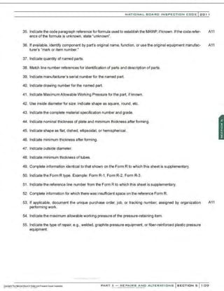
2 Jurisdiction: TheNationalBoard member jurisdictionwherethe or
ganization islocated. Alternatively, wheretheJurisdiction el~s notto
perfonn therevieworwhere thereisnoJurisdict ionor where theJurisdiction istheorganization's Authorized lnspectlonAge:ncy, theNational
Boardof Boiler andPressureVessel Inspectorswill represent theJurisdiction. At theJurisdiction'sdiscretion, theJurisdiCtion maychoose to be
amemberof the review team if theJurisdictionchooses not to be the team leader.](https://image.slidesharecdn.com/nb-232011part3repairs-220113220617/85/Nb-23-2011-part-3-repairs-34-320.jpg)
![201 1 INATIONAL. BCARC I NSPECTION CODE
2) Process sheets. travelers, or checklists shall be prepared. including the document numbers and revi-
sion to which the examination or test is to be performed. with space provided for recording results.
3) Mandatory hold/inspection points atwhich witnessing is required by the "NR" Certificate Holder's rep-
resentative or theAuthorized Nuclear Inspector shall be indicated in the controlling documents. Wor1<
shall not proceed beyond mandatory hold/inspection points without the consent ofthe "NR" Certificate
Holder's representative or theAuthorized Nuclear Inspector, as appropriate.
k) Test Control
1) Testing shall be performed in accordance with the owner's written test procedures that incorporate or
reference the requirements and acceptance limits contained in applicable design documents.
2) Test procedures shall include provisions for ensuring that prerequisites for the given test have been
met, that adequate instrumentation is availableand used, and that necessary monitoring is performed.
Prerequisites may include calibrated instrumentation, appropriate equipment, trained personnel, con-
d~ion oftest equipment and the item to be tested, suitable environmental conditions, and provisions
for data acquisition.
3) Test resuIts shall bedocumented and evaluated to ensure thattest requirements have been satisfied.
I) Control of Measuring and Test Equipment
Measures shall be established and documented to ensure that tools, gages. instruments, and other
measuring and testing equipment and devices used in activities affecting quality are of the proper
range, type, and accuracy to verify conformance to established requirements.A procedure shall be in
effect to ensure that they are calibrated and properly adjusted at specified periods or use Intervals to
maintain accuracy within specified limits. Calibration shall be traceable to known national standards,
where these standards exist, or with the device manufacturer's recommendation.
m) Quality Records
1) The owner is responsible for designating records to be maintained. Measures shall be established
for the "NR" Certificate Holder to maintain these records (See 1.8.5.1 m) 2)] required for Quality As-
surance of repair/replacement activities. These shall include documents such as records of materi-
als, manufacturing, examination. and test data taken before and during repair/replacement activity.
Procedures, specifications, and drawings used shall be fully identified by pertinent material or item
identification numbers, revision numbers, and issue dates. The records shall also include related data
such as personnel qualification,procedures, equipment, and related repairs. The "NR" Certificate Holder
shall take such steps as may be required to provide suitable protection from deterioration and damage
for all records while in his care. Also, it is requ'red that the "NR" Certificate Holder have a system for
correction or amending records that satisfies the owner's requirements. These records may be either
the original or a reproduced, legible copy and shall be transferred to the owner at his request.
2) Records to be maintained as required in NBIC Part 3, 1.8.5.1 m) 1) above may include the following:
a. An index that details the location and individual responsible for maintaining the records;
b. Data reports, properly executed, for each replacement component, part, appurtenance, piping
system, and piping assembly, when required by the design specification or the owner;
c. The required as-constructed drawings certified as to correctness;
.............. " ....
~~~~,....~b,~!~~.oc:.!'!~~Pr...aro';'~w~ : - REPAIRS ANO A L
T E R.t ,!,l}?.~.~.....-.~.-.............- ....](https://image.slidesharecdn.com/nb-232011part3repairs-220113220617/85/Nb-23-2011-part-3-repairs-54-320.jpg)


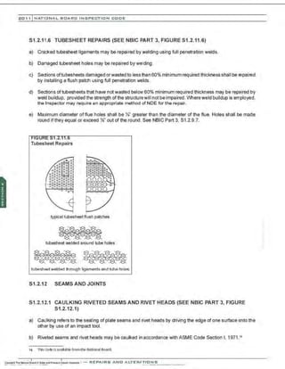
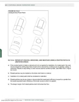
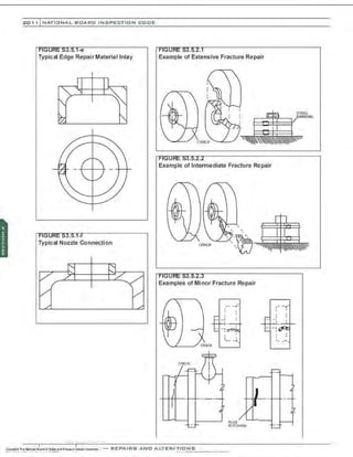
![NATIONAL BOARO INSPECTION COOE l201 1
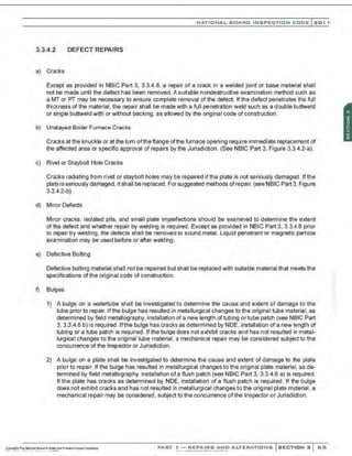
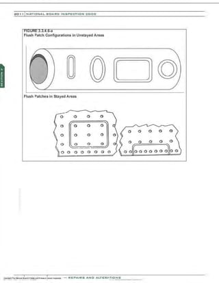
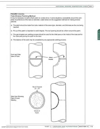
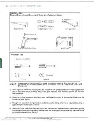
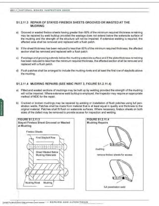
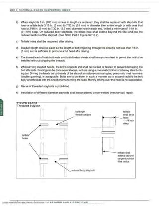
g) Blislers
A blister may be caused by a defect in the metal such as lamination where one side exposed to the fire
overheats but the other side retains its strength due to the cooling effect of the water. After the blistered
material has been removed. the remaining wall thickness shall be determined by ultrasonic thickness
testing.A surface examination using liquid penetrant testing or magnetic particle testing shall be made to
ensure the remaining material contains no defects.lfthe remaining wall thickness is adequate, in the judg-
ment ofthe Inspector, the area may be repaired by welding as covered in NBIC Part 3 , 3.3.4.3, Wasted
Areas. If the remaining wall thickness is not adequate, a plate will require a flush patch (See NBIC Part
3, 3.3.4.6[a]) and a tube will require a new length of tube or tube patch (see NBIC Part 3, 3.3.4.6 b).
3.3.4.3 WASTED AREAS
a) Shells, Drums, Headers
Wasted areas in stayed and unstayed shells, drums, and headers may be built up by welding, provided
thatin the judgment ofthe Inspector the strength ofthe structure has not been impaired. Where extensive
weld buildup is employed, the Inspector may require an appropriate method of NDE for the completed
surface of the repair. For suggested methods of building up wasted areas by welding. (See NBIC Part 3.
Figure 3.3.4.3-a).
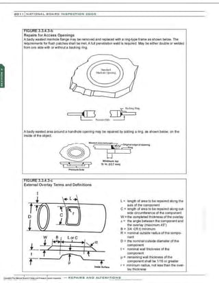
b) Access Opening
Wasted areas around access openings may be built up by welding or they may be repaired as described
in NBIC Part 3, Figure 3.3.4.3-b.
c) Flanges
Wasted flange fac.es may be cleaned thoroughly and built up with weld metaL They should be machined
in place, if possible, to a thickness not less than that ofthe original flange or that required by calculations
in accordance with the provisions of the original code of construction. Wasted flanges may also be re-
machined in place without building up with weld metal, provided the metal removed in the process does
not reduce the thickness of the flange to a measurement below that calculated above. Flanges that leak
because of warpage or distortion and which cannot be re-machined shall be replaced with new flanges
that have at least the dimensions conforming to th:l original code of construction.
d) Tubes
Wasted areas on tubes may be repaired by welding, provided that, in the judgment of the Inspector the
strength ofthe tube has not been impaired. Wheredeemed necessary, competent technical advice should
be obtained from the manufacturer or from another qualified source. This may be necessary when con-
sidering such items as size limitations of repaired areas, minimum tube thickness to be repaired, tube
environment, location of the tube in the boiler, and other similar conditions.
e) External Weld Metal Buildup
1) Pressure-retaining items that have localized internal thinning due to erosion and/or corrosion and
where the internal surface is not readily accessible may be weld repaired by depositing weld metal
on the external surface ofthe item as shown in NBIC Part 3, Figure 3.3.4.3-c. This method of repair
is subject to approval by the Inspector and the Jurisdiction, where required.
·.·..·..·;........ '·..·...,,'
PART ! -REPAIRS AND ALTERATIONS SECTION 3 67](https://image.slidesharecdn.com/nb-232011part3repairs-220113220617/85/Nb-23-2011-part-3-repairs-85-320.jpg)

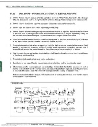
![201 1 INATIONAL. BCARC I NSPECTION CODE
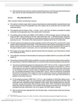
A11 5.8 STAMPING FOR FIBER-REINFORCED VESSELS
A11 The attachment of a nameplate to a repaired or altered vessel or tank shall indicate that work was performed
in accordance with requirements of this Code. The attachment of a nameplate shall be done only with knowl-
edge and authorization of the Inspector. The certificate holder responsible for repair or alteration shall apply
the stamping nameplate. Required stamping and nameplate information are shown in NBIC Part 3, 5.7.
A11 5.8.1 STAMPING FOR REPAIRS
A11 Pressure-retaining items repaired in accordance with the NBIC shall have a nameplate as required by NBIC
Part 3, 5.7. Subject to the acceptance of the Jurisdiction and the concurrence of the Inspector, nameplates
A11 may not be required for routine repairs. (See NBIC Part 3, 5.7.2[b]). In all cases, the type and extent ofrepairs
necessary shall be considered prior to waiving the requirement.
A11 5.8.2 STAMPING FOR ALTERATIONS
A11 The nameplate shall be applied in accordance with NBIC Part 3, 5.7. Location of nameplate shall be docu-
mented on Form R-2.
A11 5.9 STAMPING REQUIREMENTS FOR YANKEE DRYERS
a) Stamping is not required for repairs that do not affect pressure-retaining capability ofthe Yankee shell, as
indicated on the De-rate Curve, or other pressure-retaining parts, as indicated on the original Manufac-
turer's Data Report.
A11 b) Stamping is required for repairs that affect pressure-retaining capability ofthe Yankee Dryer shell, as indi-
cated on the De-rate Curve, or other pressure-ret;;ining parts as indicated on the original Manufacturer's
Data Report.
A11 c) Stamping is required for alterations as listed in NBIC Part 3, S5.7.2.
A11 d) Stamping, when required, shall meet the requirements for stamping in NBIC Part 3, 5.7.2. The location of
stamping shall be described in the "remarks" section of Form R-2.
5.10 ALTERNATIVE MARKING AND STAMPING FOR GRAPHITE PRESSURE
EQUIPMENT
a) GeneraI Requirements
1) This procedure may be used in lieu of the stamping and nameplate requirements defined in this sec-
tion.
2) The required data as defined in this section shall be 5/32 in. (4 mm) high, minimum.
3) The National Board Code Symbol "R" shall be used to make the impression in the cement.](https://image.slidesharecdn.com/nb-232011part3repairs-220113220617/85/Nb-23-2011-part-3-repairs-114-320.jpg)
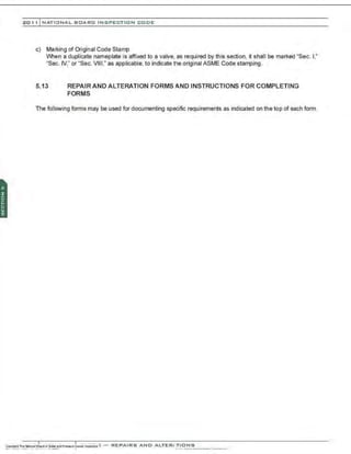
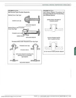
![NATIONAL BOARO INSPECTION COOE l 201
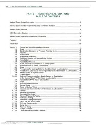
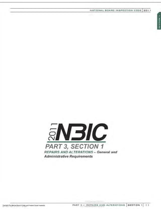
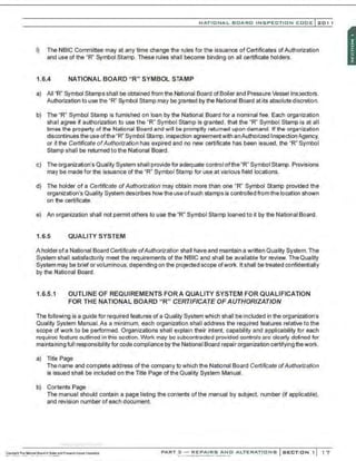
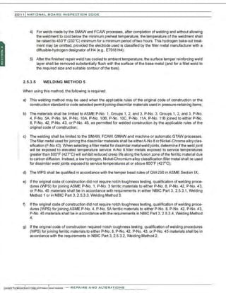
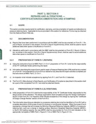
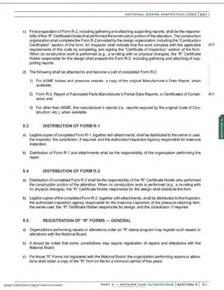
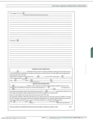
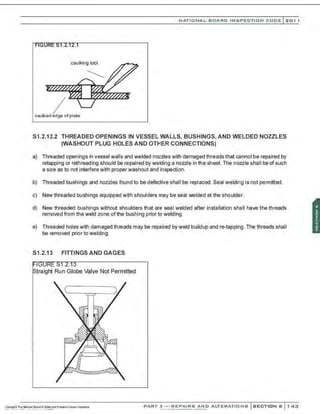
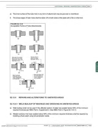
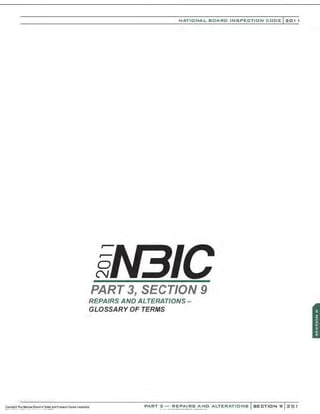
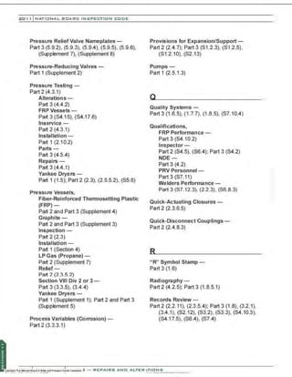
5.13.1 FORM R-1, REPORT OF REPAIR
FORM R-1 REPORT OF REPAIR
in accordance with provisions of the National BMtd Inspection Code
] , Work performed by _<D'i:iil
="m
"'
' ""
" ,.
.,
.,
,,.
, ,.
..,..
,.,
,...,
,.,,
" "
' - - - - - - - - - - - - - - - - -
2. Owner_~
~~
3
~-------------------------------------------------------
t,fla!IWJ
3.
4.
5.
6.
7.
8.
9.
Lo:ation ot installation -~
0;;;;
· = -----------------------------------------------
v.,..mo:_~
(ila>l ri~l
Item identification ® lName of original manufacturer__@
.,
6
"'-- - - - - - - -
<w~~ 9 n.
....,.,lf$!~l01' pptng;
Identifyingnos.: 0 . ® _.
®
;;:;
8
== ...:
®
:;;;
8 =--
tm•A-IU'iili h."'-J (N.:ith
i illloon.1No.I - {jlftldict!M ~) - ""h1H1
NBIC Edition/ Addenda: ~uij _@,:;
~.~
;;,
.,m
rur
, ------
Ori<rinal Code of Construction for Item:_...:®t.;
11
;,...=;;r,;;;=,..---- ®
o · (Mil'lO'/IIl<S<-'1/tl.
~nJ ~
::ai~tad~ro.l.tJ
Construction Code Used for Repair Performed: ® . --'
@7;;ui=r.;;;r,=r- -
<nu'olt,..~uom,dh~i(C'I) Wdlhl/ad dMWI
Repair Type:® D Welded D Graphite Pressure Equipment D PRP Pressure Equipment
Description of work: @ D F(lm'l R4. ReponSC)pl~tAJ)'Shmt-a!t...tl«< D FFSA Form(N'B·4ffi)i; .lttlrivd
t;J""f(IM'IIt.-4 llrte.:C~")')
------------ Pressure Test, if applied @ psi MAWP @2 psi
Replacement Parts. Attached are Manufacturer's Partial Data Reports or Form R-3s properly
completed for the following items of this report:
10. Remarksc.·_@
:,
15
L-- - - - - - - - - - - - - - - - - - - - - - - - - -
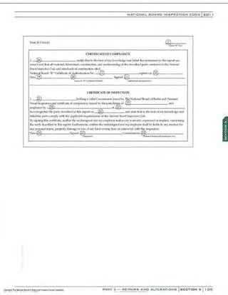
CERTIFICATE OF COMI'LIANCE
l @ ccrti fy that to the best of my krtOlVIedge and belief the s tatement; in this repQrt are
CQrrect and that all material. CQnst:ruction. and workmanship on~ Repair a.mfonns to the Nah'onal T:kmrd lnsped io11 Code.
Nation•I.Jl!lard "R'" C~rtificaleof ~horization No. ® expi,..,. on-'
@:.::
SL._ _ -----
Oate ® , ® 54,"1100 ®
(JiiJl"!'C(J{~Of)I'.U'I~...i.:ln) ~ufiOft/.«1 ~1
.,;!)a;.lf•fl
CERTIFICATE OP INSPECTION
r, @ ,holding a •alid Commi<;sion i<;..c;ood by The National Board of Boiler and Pre;:;ure
Ve~cl (n<;pectQrs a~certificat.
e ofa;,mpetency, where requ ired, i~ue.iby t~ri.C!didi<mof-"
@'"
3"-- - - - - - - - -
and employe'<! by (24) of_(
~;
22~
5) ______________
have irupected the work de~;eribed in thLc; n.-pmt Qn@ , and s tate that to the best Qf my knowledge
a nd bel:ef this work complies with the applicable requirements of the 1
atiotml Board lll$Jieditm Code.
By s igning thic; certicat~ nei ther the undersign ed nor my employer makesa ny warranty, expressed or implied, concerning
the wotk describt.
>d in thi~; report Furthennore, neither the nndersigned nQr my e mployer l'hall be liab le in a ny manner for
a ny peN;Onal in jury, prQperty damage or IOS'i of any kind aris ing from Qr connected with this inspt>Ction
Date @ Signc>d @ Comml,.ion<; .~:
®'f¥:,.,-=....,-,====-:---
1MJI«t:.wr) (N.I•Mllli~X~U tn:l Jul'iH:IS."lkon No.l
ll'is fctm nyl:e cbtaredfrom TheNitior& Be«d ciBciler flldPrezwe Veeselll'6fX!da!l, 1MSCruwerAve., ColurbtS, a-1432:19 NS66f'B'l12
PART 3- REPAIRS AND ALTERATIONS SECTIONS 101](https://image.slidesharecdn.com/nb-232011part3repairs-220113220617/85/Nb-23-2011-part-3-repairs-119-320.jpg)

![·~
:~
·•
·1
'it
~ I
'f
•
•
'f
••
~ ~
r
l
I
;n
1'1
~
;n
ID
)>
z
0
)>
4
1'1
;n
"'
:j
0
z
ID
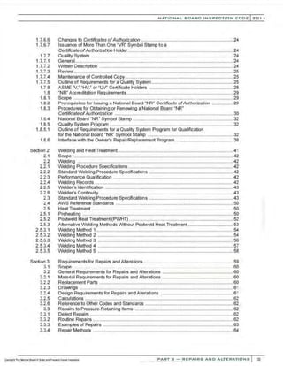
SECTION 6
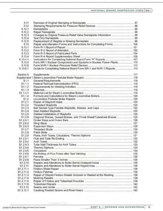
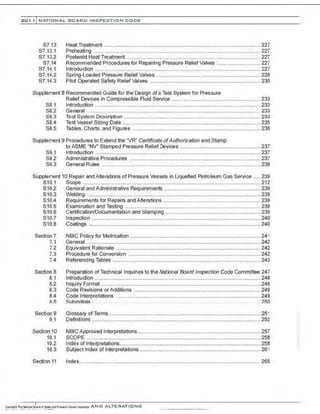
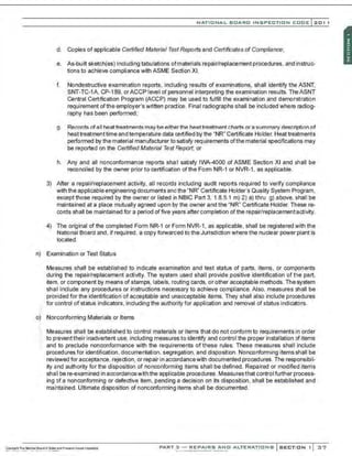
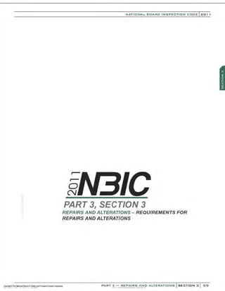
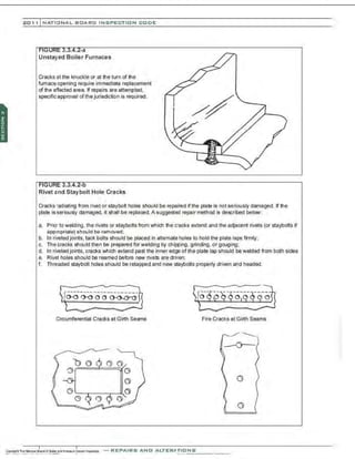
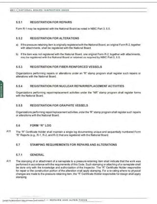
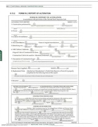
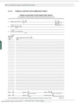
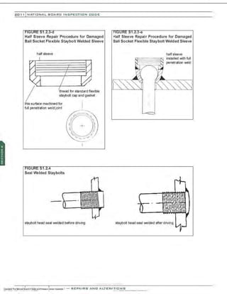
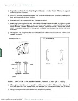
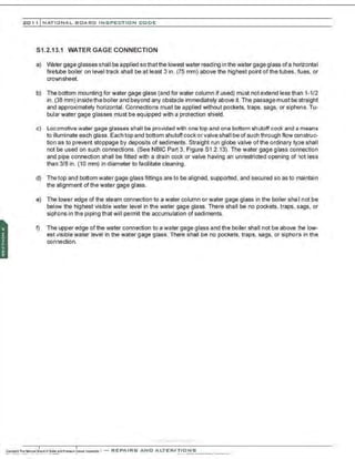
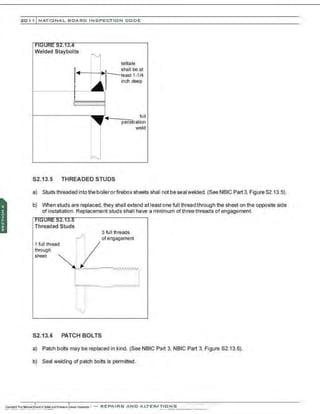
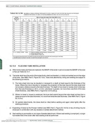
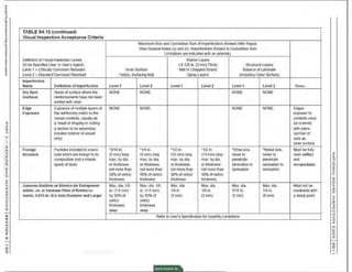
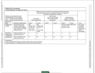
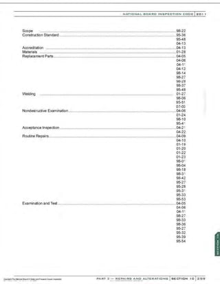
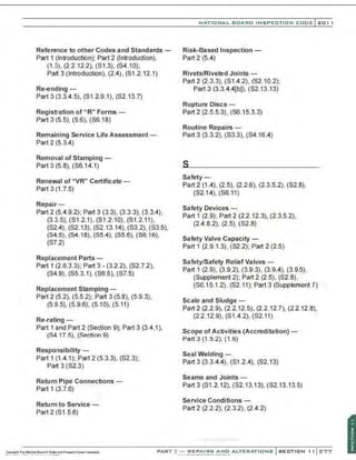
TABLE S4.12 (continued) Visual Inspection Acceptance Criteria
Maximum Size and Cumulative Sum of ImperfectionsAllowed After Repair.
(See General Notes (a) and (b). Imperfections Subject to Cumulative Sum
limitations are indicated with an asterisk).
Definition ofVisuallnsa:>ection Levels Interior Layers
(to be Specified Useror User'sAgent): (-{l.125 in. l3 mm] Thick) Structural Layers
Level I = Critically Corrosion Resistant Inner Surface Mat or Chopped Strand Balance of Laminate
Level 2= Standard Corrosion Resistant Veil(s), Surfacing Mat Spray LayeiS (Including Outer Surface)
Imperfection
Name Definition of Imperfection Levell Level 2 Levell Level2 Levell Level2
Pimples Small, sharp, conical el- 'Max. height 'Max. height No Limit No Lim~
(surface) evations on the surface of a ofdiameter ofdiameter
laminate 1/64 in. 1164 in.
(0.4 mm) (0.4 mm)
Pit Small crater in thesurface of ' 1/8 in. '1/8 in. '1/4 in. '1/4 in.
(surface) a laminate (3mm) max. (3mm)max. (6 mm)max. (6 mm)max.
lly30%of by30%of by 1/ 16 in. by 3/32 in.
veil(s) thick- veil(s) thick- (1.5 mm) deep (2.5 mm) deep
ness max. ness max. max. max.
Porosity Presence of numerous visual None more None more None to fully penetrate theexte-
(surface) tiny pits (pinholes). approxi- than 30% than 50% rior get ooatorget ooated exterior
mate dimension 0.005 in. (0.1 ofveil(s) thick- ofveil(s)thick- veiLNo quantity lim~.
mml) (for example, 5 in. any ness ness
sq. in. [630 sq. mm])
Scratches Sh·allow mal1<s, grooves, NONE NONE .,None more *None more
(surface) fur<>ws,or channels caused than 6 in. long than 12 in.
by improper healing (150 mm) long
(300mm)
Wet Blisters Rounded elevation of the sur- "'None over ' None over No Limit No limit
(surface) face, somewhat resembling a 3/16 in. (5 3/16 in. (5
blister of the human skin, not mrn)dia. by mm)dia. by
reinforced 1/16 in. (1.5 1/16 in. (1.5
mm) in height mm) in height
Wet Out Resin has failed to saturate NONE NONE NONE NONE Dry mat or prominent and dry wo-
Inadequate reinforcing (particulartywoven ven roving pattern not acceptable;
roving.) discernible l>ut fully saturated
woven pattern acceptable
•.·.·.·.
·........._ . ...
Notes
Must be tully
resin filled and
wetted;
generally
captured sand-
ing dust
No libelS
should be
exposed
No libelS
should be
exposed
No fibers
should be
exposed
Must be fully
resin filled; not
drips loosely
glues to 5Jr-
face, which are
to be removed
Split testson
cutouts may
be used to
discern degree
of saturation
on reinforcing
layeiS
N
0
z
~
0
z
)>
r
m
0
)>
;n
0
z
ID
11
1'1
n
-t
0
z
n
0
0
1'1](https://image.slidesharecdn.com/nb-232011part3repairs-220113220617/85/Nb-23-2011-part-3-repairs-208-320.jpg)
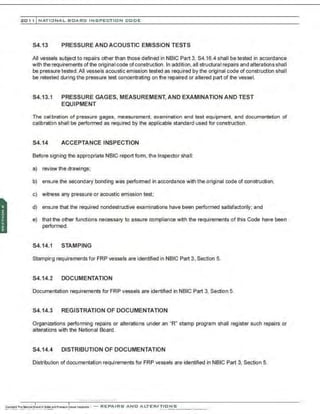
![NATIONAL BOARD INSPECTION CODE l 201 1
b. The subsequent steps shall be followed:
1. Apply the primer (3 to 5 mils [0.08 to 0.13 mm]) to the prepared surface, and allow primer to
cure.
2. Coat the primed surface with the same resin to be used in the Iaminate repair. Apply 4 in.
(1 00 mm) x 14 in. (360 mm) piece of polyester. such as Mylar®, strip to one edge of primed
area. Allow the polyester film to protrude from beneath the patch.
3. Apply two layers of 1-1/2 oz/sq. ft (0.46 kg/sq. m) chopped strand mat saturated with the
same resin that will be used for the repair. Mat shall be 12 in. (305 mm) x 12 in. (305 mm)
square.
4. Allow the mat layers to cure completely, this may be verified by checking the hardness of
the laminate.
5. Pry patch from surface using a screwdriver, chisel, or pry bar.
6. A clean separation indicates a poor bond.
7. Torn patch laminate or pulled substrate indicates that the bond is acceptable.
c. If the bond is not adequate, go back to step (a) and repeat the procedure.
Note: If the repair area is smaller than the test patch dimensions, decrease the test patch size
accordingly.
d. As a last resort, if the previous procedure does not provide an adequate bond, the permeated
laminate must be handled differently using the following procedure:
1. Hot water wash the equipment.
2. Abrasive blast with #3 sand, or equal, and allow to completely dry.
3. Prime with the recommended primer, an area 12 in. (305 mm) x 12 in. (305 mm) and apply
a test patch.
4. Prime a second spot 12 in. (305 mm) x 12 in. (305 mm) and prime with a recommended
epoxy resin primer.
5. Allow this primer to cure.
6. Water wash, dry, and lightly abrasive blast the epoxy primer.
7. Apply the test patches to both areas.
e. Pull both test patches after they are fully cured.
f. If both test patches are good, prime the vessel with the preferred primer. If only one test patch is
good, prime the vessel with the successful primer.
Note: If the repair area is smaller than the test patch dimensions, decrease the test patch size
accordingly.
PART 3- REPAIRS AND ALTERATIONS SECTION 6 1 99](https://image.slidesharecdn.com/nb-232011part3repairs-220113220617/85/Nb-23-2011-part-3-repairs-217-320.jpg)
![201 1 INATIONAL. BCARC I NSPECTION CODE
g. If neither patch bonds, the vessel is probably not capable of bonding a patch and shall not be
repaired.
3) Laminate Repair
a. Repairs can be accomplished by adding back the correct corrosion barrier surface material as
specified on the Fabricator's design drawings.
b. All repairs shall be made with the same type of resin and reinforcement materials used tofabricate
the original vessel corrosion barrier. Laminate quality shall be in accordance with Table S4.12.
The acceptance criteria shall be as agreed by the Certificate Holder and Owner or as required by
the code of construction.
1. Apply the selected primer (3 to 5 mils [0.08 to 0.13 mm]) and allow to dry to the touch.
2. Continue with the specified laminate using the proper resin and cure. The first layer of
chopped strand mat used in the repair shall extend a minimum of 1 in. (25 mm) past the
damaged area. The following chopped strand mat layer shall extend a minimum of 1 in.
(25 mm) past the first layer, (in this manner, the entire area that was removed will now be
filled with the mat layers. If additional layers are required to fill the removed surface, they
must be applied), followed by the specified layer(s) of veil. The veil(s) shall extend a mini-
mum of 1 in. (25 mm) past the last chopped strand mat layer.
3. Apply a final coat of resin over entire surfacing veil. This final coat should contain a small
amount ofwax to prevent air contact, which might inhibitthe cure. Allow laminate to achieve
the manufacturer's recommended Barcol hardness before finalizing the repair.
Note: Apply heat to finalize the cure if hardness is not achieved.
S4.18.2.2 TYPE 1B - REPAIR OF THE CORROSION BARRIER FOR VESSELS WITH
PRECISION BORES
Vesselswith precision bores are commonly used when a device is installed inside the vessel and a seal between
the device and the inside diameter is required.A corrosion barrier ofa precision bore vessel is (susceptible) to
scratching and damage that may affect performance and service life of the vessel or the device placed inside
the vessel. Many times this damage may extend into areas ofthe vessel that cannot be reached. Before start·
ing. ensure that the damaged area can be reached.After the Inspector has verified that the repair procedure
is acceptable, the repair shall be performed by the Certificate Holder as follows:
a) Surface Preparation
1) The surface area that is damaged must be removed by abrasive blasting or grinding, to expose sound
laminate. No more than 0.020 in. (0.51 mm) may be removed from the wall ofthe vessel. The repaired
area shall be beveled into the good areas surrounding the damage.
2) Notethat any cracks, delaminations, or permeated surfaces must be removed. lfthedamage is deeper
than the corrosion barrier and the material removed reaches the structural laminate, the vessel is not
repairable.An adequate size abrasive. or proper sanding disc must be used to obtain a 2 to 3 mil (0.05
to 0.08 mm) anchor pattern to the area that requires the repair.](https://image.slidesharecdn.com/nb-232011part3repairs-220113220617/85/Nb-23-2011-part-3-repairs-218-320.jpg)
![NATIONAL BOARD INSPECTION CODE l 201 1
3) Preparation of any surface requires that basic rules, common to all substrates, be followed. These
rules are as outlined below:
a. Surface must be free of contaminants;
b. Surface must be structurally sound;
c. Surface must have adequate anchor pattern;
d. Surface must be dry;
e. Surface must be primed with recommended primer.
Note: After the surface has been properly prepared, it must be kept clean and dry until laminating
can be started. Dust, moisture, or traces of oil that come in contact with the surface may act as
a mold release or act to inhibit the cure and prevent a good secondary bond. Laminating should
be done within two hours of the surface preparation.
b) Applying Test Patches to Verify Adequate Surface Preparation
1) Test patches may be applied to any substrate that will require a secondary bond to determine the
integrity of the bond prior to the application of the laminate.
2) The subsequent steps shall be followed:
a. Apply the primer (3 to 5 mils [0.08 to 0.13mm]) to the prepared surface, and allow primer to cure:
b. Coat the surface with the same resin to be used in the laminate repair. Apply a small stripof poly-
ester film, such as Mylar®, strip to one edge of primed area. Allow the polyester film to protrude
from beneath the patch;
c. Apply two layers of 1-1/2 oz. per sq. ft. (0.46 kg per sq. m) chopped strand mat saturated with the
same resin that will be used for the repair:
d. Allow the mat layerstocure completely; this may be verified by checking the hardness ofthe laminate.
Ifrequired, heat may be used to cure the material providing it is compatiblewith the initial resin used
in the fabrication of the vessel;
e. Pry patch from surface using a screwdriver. chisel, or pry bar;
f. A clean separation indicates a poor bond:
g. Torn patch laminate or pulled substrate indicates that the bond is acceptable;
h. If the bond is not adequate, go back to step (a) and repeat the procedure again .
Note: If the repair area is smaller than the test patch dimensions, decrease the test patch size
accordingly.
3) Ifneither patch bonds. thevessel is probably not capable ofbonding a patch and shall not be repaired.
PART 3- REPAIRS AND ALTERATIONS SECTION 6 201](https://image.slidesharecdn.com/nb-232011part3repairs-220113220617/85/Nb-23-2011-part-3-repairs-219-320.jpg)
![201 1 INATIONAL. BCARC I NSPECTION CODE
c) Laminate repair
1) Repairs can be accomplished by adding back Ihe correct corrosion barrier surface material as speci-
fied on the Fabricator's design drawings.
2) When possible, repairs shall be made with the same type of resin and reinforcement materials used
to fabricate the original vessel corrosion barrier. Laminate quality shall be in accordance with Table
S4.12, or the original code of construction. However, when the original material of construction was
gelled and post cured at elevated temperatures, using the same resin may not be possible. In this
case an alternate resin systern may be used.
a. Apply the selected primer (3 to 5 mils [0.08 to 0.13 mm]) (as required for polyester and vinyl ester
resins) and allow to dry to the touch.
b. Continue with the specified laminate usingthe proper resin and cure. The first layer of non-woven
polyester veil used in the repair shall extend to the exact edge of the damaged area. If additional
layers are required to fill the removed surface, they must be applied. followed by the specified
layer(s) ofveil.
c. Apply a final coat of resin over entire surfacing veil. If this final coat is a vinyl ester or polyester
material, it should contain a small amount of wax to prevent air contact, which might inhibit the
cure. Allow laminate to achieve the manufacturer's recommended Barcol hardness before final-
izing the repair.
Note: Apply heat to finalize the cure if hardness is not achieved.
d. After the repair has been properly cured, remove any excess material with the appropriate sand-
ing tools to obtain a smooth surface that blends into the surrounding area. Cane should be taken
to ensure that the final inside diameter of the repaired area matches that ofthe surrounding area
and also conforms to the original supplier's specifications.
S4.18.2.3 TYPE 2- CORROSION BARRIER AND INTERNAL STRUCTURAL LAYER
REPAIRS
a) The procedure for the Type 1a repair must be followed with the exception of additional layers (structural
layers) that must be removed if the structure is also damaged. The repair area must be tapered similar
to the Type 1a, and all of the structural layers must be replaced making sure that the mat layers increase
in length and width by at least 1 in. (25 mm). The structural laminate sequence and thickness must be
approved by the Inspector, and proper calculations and the repair plan must be reviewed and approved
by a P.E. familiar with the work involved prior to the job.
b) Surface preparation, priming, and laminate repair must be done per Type 1a procedure.
S4.18.2.4 TYPE 3- EXTERNAL STRUCTURAL LAYER REPAIRS
a) Surface Preparation
•'
:·
1) The surface area that is damaged is to be repaired by removing the damaged area either by abrasive
blasting or grinding to expose sound laminate. The repair area must have a bevel of 2 in. (50 mm)
minimum. The ground or blasted surface must extend a minimum of4 in. {1 00 mm) past the damaged
area into the sound solid structural laminate (making sure that no layers are removed in these 4 in.
(100 mm). or as calculated accordingly.
Coontv.The--;...;-ona1
:&aii:!Oil8oolor.rldPr...u-ovcuet~ : - REPAIRS AND ALTER.JTIONS
..._ .~ . ~ ~ ... .. . ....J ••••• - · - • ..•• ~ . . ...... ......-. ~ - ...... .... ...- ...](https://image.slidesharecdn.com/nb-232011part3repairs-220113220617/85/Nb-23-2011-part-3-repairs-220-320.jpg)
![NATIONAL BOARD INSPECTION CODE l201 1
2) Note that any cracks ordelaminations must be removed.An adequate size abrasive or propersanding
disc must be used to obtain a 2 to 3 mil 0.05 to 0.08 mm) anchor pattern.
3) Preparation of any surface requires that basic rules. common to all substrates. be followed. These
rules are as outlined below:
a. Surface must be free of contaminants;
b. Surface must be structurally sound;
c. Surface must have adequate anchor pattern;
d. Surface must be dry;
e. Surface must be primed with recommended primer.
Note: After the surface has been properly prepared, it must be kept clean and dry until laminating
can be started. Dust, moisture, or traces of oil that come in contact with the surface may act as a
mold release or inhibit the cure and prevent a good secondary bond. Laminating should be done
within two hours ofthe surface preparation.
b) Applying Test Patches to Verify Adequate Surface Preparation
1) Test patches may be applied to any substrate that will require a secondary bond to determine the
integrity of the primer bond prior to the application of the laminate.
2) The subsequent steps shall be followed:
a. Apply the primer (3 to 5 mils [0.08 to 0.13mm]) to the prepared surface, and allow primerto cure;
b. Coat the primed surface with resin to be used in the repair. Apply 4 in. (100 mm) x 14 in. (350 mm)
Mylar® strip to one edge of primed area. Allow polyester film to protrude from beneath the patch;
c. Apply two layers of 1-1/2oz.per sq.ft. (456 g/m2) chopped strand mat saturated with the specified
resin that will be used for the repair. Mat shall be 12 in. (305 mm) x 12 in. (305 mm) square;
d. Allow to cure completely; this may be verified by checking the hardness of the laminate;
e. Pry patch from surface using a screwdriver. chisel, or pry bar;
f. A clean separation indicates a poor bond;
g. Torn patch laminate or pulled substrate indicates that the bond is acceptable;
If the bond is not adequate, go back to step one and prepare the surface again.
Note: If the repair area is smaller than the test patch dimensions, decrease the test patch size
accordingly.
c) Laminate Repair
1) Repairs can be accomplished by adding back the correct equivalent contact molded laminate material
as specified on the Fabricator's design drawings, or in the Repair Plan.
,·..-..-,·,...·...., .....·..
PART 3- REPAIRS AND ALTERATIONS SECTION 6 203](https://image.slidesharecdn.com/nb-232011part3repairs-220113220617/85/Nb-23-2011-part-3-repairs-221-320.jpg)
![201 1 INATIONAL. BCARC I NSPECTION CODE
2) All repairs shall be made with the same type of resin and reinforcement materials used to fabricate
the original vessel. Laminate quality shall be in accordance with the original construction code as
specified in the vessel drawings and specifications.
a. Apply the selected primer (3 to 5 mils [0.08 to 0.13 mm]) and allow to dry to the touch.
b. Continue with the specified laminate using the proper resin and cure.
c. Fill the removed layers with the same sequence as the original structural thickness, making sure
that the layers are increasingly larger as the laminate is applied (in the case of filament wound
structure, an equivalent contact molded thickness must be used for the repair calculations). The
first bond of the repair shall cover one degree times the width in the axial direction and shall be
centered. The repair shall extend completely around the circumference using contact molded
procedures as set forth in the code of construction.
d. After the area is completely filled with the proper laminate, a reinforcing laminate shall be applied
over the entire surface with a minimum overlap of 4 in. (1 00 mm) over the original shell, or as
shown in the calculations, whichever is greater. This overlay thickness shall be calculated in the
same way as the reinforcing pad of a nozzle with the diameter equal to the damaged area. The
design shall be in accordance with the ori9inal construction code. Allow the laminate to achieve
the manufacturer's recommended Barco! hardness before finalizing the repair.
Note: Apply heat to finalize the cure if hardness is not achieved.
e. A pressure test shall be performed per NBIC Part 3, 4.4.1.
S4.18.2.5 TYPE4 - ALTERATIONS
a) Alterations, such as the addition of a nozzle or supports, must be designed according to the original
construction standard. In the case of nozzles, the internal overlay is required according toASME RTP-1
Figure 4-8 or 4-9 (overlay "ti"). The procedure for preparing the inside surface is the same as the Type 1
repair. The external reinforcing pad shall be designed and installed according to the original construction
standard. Surface preparation for the external overlay shall be according to the Type 3 repair procedure.
b) After the alteration is completed, a pressure test shall be performed in accordance with NBICPart3, 4.4.1.
As an option . an Acoustic Emission test can be performedto monitor the repaired area during the pressure
test.
S4.18.2.6 TYPE 5- MISCELLANEOUS GENERAL EXTERNAL REPAIRS OR ALTERATIONS
External repairs or alterationsthat are performed on nonpressure retaining parts, shall be calculated according
to the original construction standard. The Inspector and the P.E. must review and approve such modifications.All
repairs and alterations shall be done according to the Type 3 repair procedure, with the exception of removing
damaged layers from the structure. Surface preparation shall be restricted to the external layer of the vessel.
S4.18.2.7 TYPE 6 - THERMOPLASTIC REPAIRS
a) The surface area that is damaged must be recondiltoned so thatthe thermoplastic liner geometry matches
that of its contacting laminate. Surfaces that are cut or torn, or missing sections, shall be repaired by
plastic welding. Welding practice, including choice ofwelding equipment, weld surface preparation, and
weld temperature shall conform to Appendix M-14 ofASME RTP-1. For materials not specified in these](https://image.slidesharecdn.com/nb-232011part3repairs-220113220617/85/Nb-23-2011-part-3-repairs-222-320.jpg)
![NATIONAL BOARD INSPECTION CODE l201 1
d) In addition , the duties of the Registered Inspector are summarized below:
1) Verify the organization performing the repair or modification activity is properly accredited and in pos-
session of a current Certificate ofAuthorization to apply the "TR" Stamp issued by the National Board
and is working to an approved Quality Control System;
2) Verifythat the design, ifrequired, for the modifi;ation ofthe vessel is approved by a Design Certifying
Engineer, or Designated Approval Agency or other applicable individual;
3) Verify the materials to be used to make the repair or modification are approved for use and comply
with applicable Code requirements;
4) Verify the welding procedures and welders or welding operators are properly qualified;
5) Verify that all heat treatments, if required, including PWHT have been performed in accordance with
the applicable standards and that the results are acceptable;
6) Verify that all NDE, impact tests, and other tests have been performed when required, and that the
results are acceptable;
7) Make a visual inspection of the work performed to confirm there are no visible defects or deviations
from Code requirements;
8) Perform external and internal visual inspections, if the vessel is equipped with a manway, andwitness
the hydrostatic or pneumatic pressure test and/or leak tightness test when they are required;
9) Verify the correct nameplate Is properly attached to the vessel and that the current test and Inspection
markings are properly attached and displayed on the proper vessel;
10) Sign the FormTR-1 and, as appropriate, formTR-2.
S6.8 WELDING
a) Welding shall be performed in accordance with the requirements ofthe original code of construction used
for the fabrication of the pressure vessel. For hydrogen control when low alloy steel filler metals are used,
the filler metal classification shall include an H4 supplemental diffusible hydrogen designator (maximum
4 ml [H2]/100 g deposited metal) for each ofthe following:
1) electrodes for shielded metal arc welding conforming to SFA-5.5;
2) electrodes and fluxes for submerged arc welding conforming to SFA-5.26;
3) electrodes and rods for gas shielded metal arc welding conforming to SFA-5.28;
4) electrodes for flux-cored arc welding conforming to SFA 5.29.
b) Practices used for controlling storage and exposure of filler metals shall be those developed by the "TR"
Certificate Holder or those recommended by the fi!ler metal manufacturer.
PART 3- REPAIRS AND ALTERATIONS SECTION 6 213](https://image.slidesharecdn.com/nb-232011part3repairs-220113220617/85/Nb-23-2011-part-3-repairs-231-320.jpg)
![201 1 INATIONAL. BCARC I NSPECTION CODE
b) Prior to performing weld repairsto pressure relief valve (PRV) parts, the "R" Certificate Holder shall receive
repair information required by NBIC Part 3, S7.3 a) from the "VR" Certificate Holder responsible for the
pressure relief valve repair.
1) PRV part weld repairs shall be performed under the "R" Certificate Holder's quality system; however.
the requirements for in-process involvement ofthe Inspector (see NBIC Part 3, 1.3.2) may bewaived.
The requirement for stamping is waived.
2) The process of identifying and controlling repairs shall be documented in the "R" Certificate Holder's
quality system.
3) PRV part repairs shall be documented on a Form R-1 with a statement under Remarks "PRV Part
Repair." The owner's name and location of installation shall be that of the "VR" Certificate Holder.
The information received from the 'VR" Certificate Holder as required in Supplement S7.3(a) shall be
noted under 'Description of Work."
4) Upon completion of the repair, the repaired part and completed Form R-1 shall be retumed tothe 'VR"
Certificate Holder responsible for completing the PRV repair.
S7.4 MATERIALS FOR PRESSURE RELIEF DEVICES
·.
T~e materials used in making repairs shall conform to the requirements ofthe original code of construction.
Ttie 'VR" Certificate Holder is responsible for verifying identification of existing materials from original data,
drawings, or unit records and identification ofthe materials to be installed.
S7.5 REPLACEMENT PARTS FOR PRESSURE RELIEF DEVICES
a) Critical parts shall be fabricated by the valve manufacturer orto the manufacturer's specifications. Critical
parts are those that may affect the valve flow passage, capacity, function, or pressure-retaining integrity.
b) Critical parts not fabricated by the valve manufacturer shall be supplied with material test certification for
the materia1used to fabricate the part.
c) Replacement criticaIparts receiving records shaII be attached or betraceableto the valve repair document
(see NBIC Part 3. S7.3[a]). These records shall conform to at least one of the following.
1) Receiving records documenting the shipping origin of the part fabricated by the valve manufacturer
(such as packing list) from the valve manufacturer or assembler ofthe valve type;
2) A document prepared by the 'VR" Certificate Holder certifying that the replacement part used in
the repair has the manufacturer's identification on the part or is otherwise labeled or tagged by the
manufacturer and meets the manufacturer's acceptance criteria (e.g., critical dimensions found in
maintenance manual);
3) Receiving records for replacement critical parts obtained from a source other than the valve manu-
facturer or assembler of the valve type shall include a Certificate of Compliance that provides as a
minimum:
a. The part manufacturer and part designation;](https://image.slidesharecdn.com/nb-232011part3repairs-220113220617/85/Nb-23-2011-part-3-repairs-240-320.jpg)
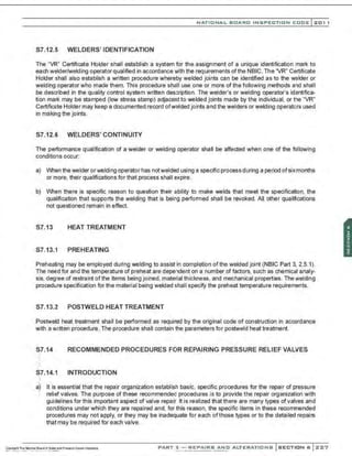
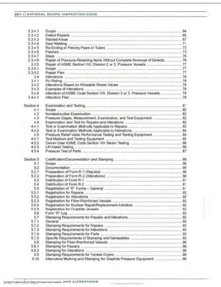
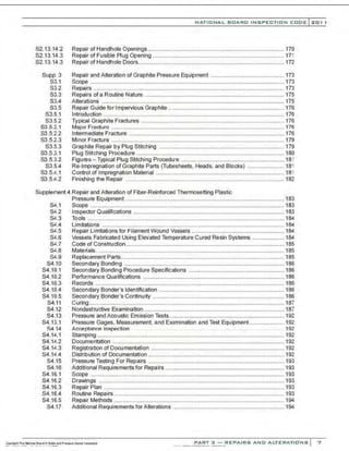
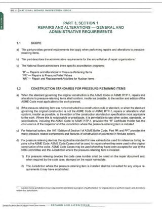
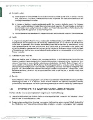
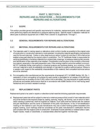
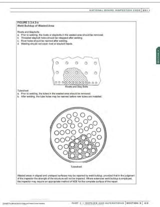
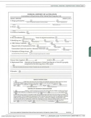
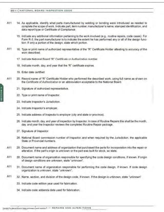
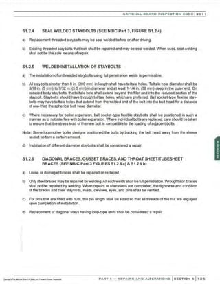
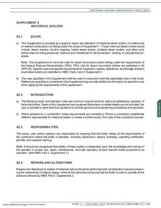
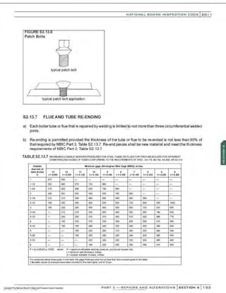
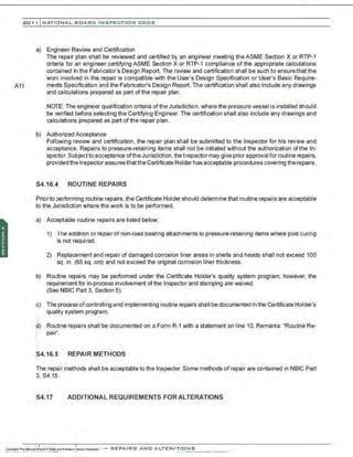
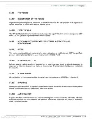
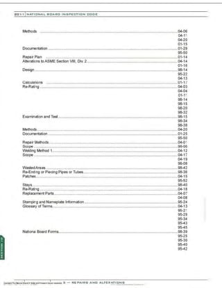
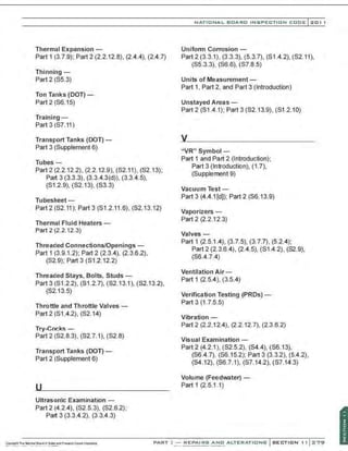
![Schematic of Test Equipment without Accumulator
Control Valve
and Bypass
~stvalve
Test Vessel
NATIONAL BOARD INSPECTION CODE l201 1
Test
Medium
Source
Drain Trap
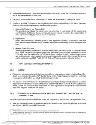
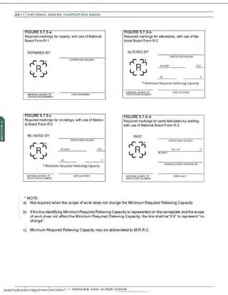
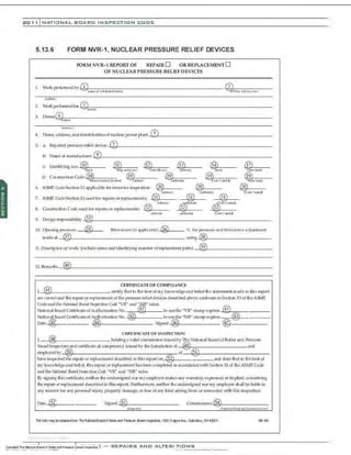
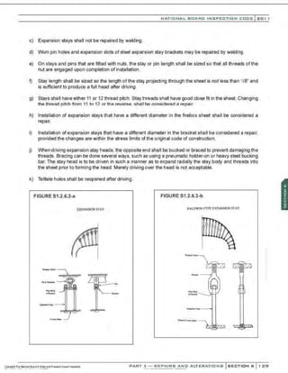
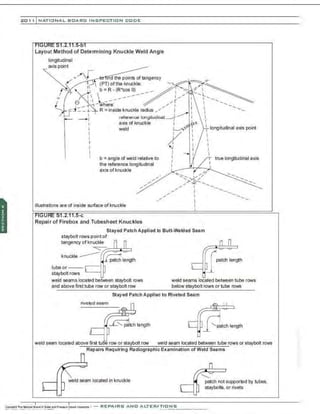
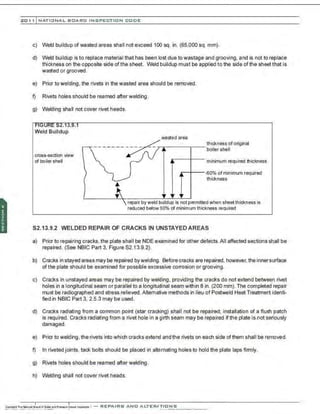
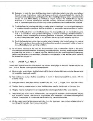
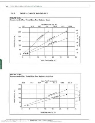
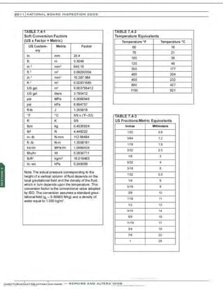
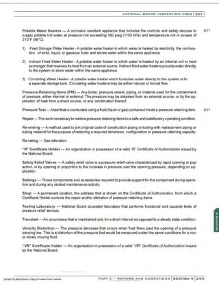
S8.4 TEST VESSEL SIZING DATA
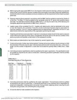
a) Recommended test vessel sizes are given in NBIC Part 3, Figures 58.4-a and 58.4-b for a configuration
using one vessel fed directly from the source of the test medium. Figure 58.4-a gives the test vessel size
in cu . ft. vs. the valve orifice area in sq. in. for dry, saturated steam. Curves are shown for set pressures
up to 500 psig (3.45MPa) for three different blowdowns: 4%, 7%, and 10%. The source is assumed to be
capable of feeding the test vessel at 2500 lbs/hr. (1135 kg/hr). Figure 58.4-b gives similar curves for air
with a source capable of feeding the test vessel at 200 SCFM (5.66 cu. m./minute).
b) For valves, with effective orifices less than 1.28 sq . in. (826 sq. mm), the size ofthe test vessel needed
becomes less dependent on the flow capacity of the source. For these valves, a 15 cu. ft. (.425 cu. m.)
minimum size test vessel is recommended. This should allow the accurate measurement and setting of
blowdown for small valves. This minimum size should also be adequate for determining set pressures of
larger valves; however,Iarger test vessels must be used ifblowdown isto be set accurately. It is recognized
thatthere are practical limits on the size and maximum pressure ofa test vessel used to demonstrate pres-
sure reliefvalve operational characteristics. In such cases, determination of valve set pressure remains
the only vioble production ond repoir test option. The recommended minimum size test vessel (15 cu. ft.
: (0.425 cu. m]) is normally adequate for this purpose.
PART 3- REPAIRS AND ALTERATIONS SECTION 6 2::;15](https://image.slidesharecdn.com/nb-232011part3repairs-220113220617/85/Nb-23-2011-part-3-repairs-253-320.jpg)


![201 1 INATIONAL. BCARC I NSPECTION CODE
Examination -
Part 1 (5.4); Part 2 (2.3.3), (2.3.5.4), (2.3.6),
(2.4.5), (Section 4), (5.3.1 ), (5.3.8),
(S1.4.2), (S2.4), (S2.4.4), (S2.5);
Part 3 (3.3.4.2), (Section 4), (4.4), (S4.2),
(S4.13.1), (S4.15), (S6.17), (S4.17.6),
(S5.2). (S6.10), (S6.12), (S6.17)
Examples or Repairs and Alterations-
Part 3 (3.3.3), (3.4.3)
Exfoliation-
Part 2 (2.4.4), (3.3.1), (S6.6.3.1[e])
Exhibits-
Part 3 (1 .6.5.1[q]). (1 .7.7.5[p]). (1.8.5.1[s])
Exit and Egress -
Part 1(2.4.1), (2.5.3), (3.4.1)
Expansion Tanks -
Part 1 (3.7.9.1). (3.7.9.2); Part 2 (2.3.6.3)
Expansion and Support-
Part 1 (2.7.3), (3.3.1), (3.7.9), (3.9.4), (4.3.3);
Part 2 (2.4.7)
External Inspections,
Boilers-
Part 2 (2.2.5)
Pressure Vessels -
Part 2 (2.3.3), (S7.4)
Piping -
Part 2 (2.4.4)
Graphite-
Part 2 (S3.4)
FRP-
Part 2 (84.4), (84.7)
External Weld Metal Buildup-
Part 3 (3.3.4.3[e])
Failure Mechanisms-
Part 2 (3.4), (S6.6.4)
Fatigue -
Part 2 (3.4.1), (5.3.8.6)
Federal Railroad Administration (FRA) -
Part 2 (S1 .3); Part 3 (S1 .1.1)
Feedwater-
Part 1 (2.5.1). (3.7.4); Part 2 - (2.2.10.4),
(2.2.12.5), (S2.7.1). (S2.14), (S2.7.1i
Fiber-Reinforced Thermoset Plastic
Equipment (RTP, FRP)-
Part 2 (Supplement 4); Part 3 (Supplement 4)
Field Repairs for Relief Devices-
Part 3 (S7.7)
Firebox -
Part2 (2.2.10.2), (2.2.12.9), (S1.1), (S1 .4.2),
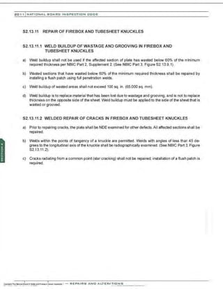
(S2.11); Part 3 (S1 .2.10.2), (S1.2.11 .1),
(S2.13.10.4), (S2.13.11)
Fire Damage -
Part 2 (5.3.8.5), (5.7.7). (S7.4)
Fittings -
Part 1 (3.8); Part 3 (S1 .2.13)
Flanges-
Part 1 (5.2.3); Part 2 (2.2.10.3);
Part 3 (3.3.4.3[c))
Forced-Flow Steam Generators -
Part 1 (2.9.2)
Forms -
Part 1 (1.4.1); Part2 (5.5), (S2.12);
Part 3 (Section 5). (S6.15)
Distribution -
Part 3 (5.3), (5.4)
Guide for Completing -
Part3 (5.2), (5.13)
Registration -
Part 3 (5.5.1), (5.5.2)
Foundations-
Part 1 (2.3.1)](https://image.slidesharecdn.com/nb-232011part3repairs-220113220617/85/Nb-23-2011-part-3-repairs-288-320.jpg)
![201 1 INATIONAL. BCARC I NSPECTION CODE
Installation Condition -
Part 1; Part 2 (S4.9.1)
Installation Requirements-
Part 1
Insulated Vessels, Inspection-
Part 2 (2.3.6.4(b)). (S4.7.1)
Instruments and Controls-
Part 1 (2.8). (2.9.2). (3.5.3). (3.5.6). (3.8). (4.4).
(S1.2)
Interface with Owners Repair/Replacement
Program (Nuclear)-
Part 3 (1 .8.6)
lntergranular Corrosion-
Part 2 (3.3.2)
Internal Inspections-
Part 2 (1.5.3), (2.3.4), (2.4.5), (S4.8), (S7.5).
(S2.5)
Interpretations-
Part 1, Part 2 and Part 3 (Introduction). (8.4),
(Section 10)
Interrupted Service-
Part 2 (5.3.7.2[g])
Insulation MateriaUinsulation-
Part 1 (3.3.2); Part 2 (2.2.7), (2.3.3), (2.4.6),
. (S7.4)
lnspector-
p:
art 1 (2.10), (4.6), (S1.2); Part 2 (1.4), (1.5),
(2.2). (2.3), (2.4). (2.5). (Section 4),
(5.3.3), (S4.5), (S2.4), (S4.2). (S4.5),
(S6.4.2); Part 3 (1.3), (3.3.2), (3.3.4.1),
(3.3.5), (3.4.1).(3.4.4). (4.4.1), (4.4.2).
(S2.8), (S2.9), (S2.10), (S3.2), (S4.2),
(S6.7.1)
Jurisdiction-
Part 1 (Foreword), (Introduction), (1.4.3);
Part 2 (Foreword), (Introduction). (1 .2),
(2.5.8), (5.3.1). (5.3.4), (5.4.7), (5.5.1),
(S1 .2); Part 3 (Foreword), (Introduction).
(3.3.2), (3.3.4.3(e)), (3.4.1), (3.4.2). (4.2),
(4.3), (4.4), (4.4.1), (4.4.2), (4.5). (5.7),
(5.9.5), (S2.2), (S4.16.4). (S6.3)
Jurisdictional Authority-
Part 1 (Foreword); Part 2 (Foreword), (S7.1);
Part 3 (Foreword), (S7.10)
Jurisdictional Participation -
Part 3 (1 .7.2)
Jurisdictional Precedence -
Part 1, Part 2 and Part 3 (Introduction)
Jurisdictional Requirements-
Part 1 (1.4)
Knuckles-
Part2 (2.2.8); Part 3 (81 .2.11.5), (S2.13)
Ladders and Runways-
Part 1 (2.4.2), (3.4 2)
Lamination -
Part 2 (3.4.7). (S4.3), (S4.10), (S4.18)
Lap Joints/Seams-
Part 2 (3.3.1). (3.4.9), (S2.10.6). (86.6.3.1);
Part3 (S1.2.10), (S1 .2.10), (S1.2.11),
(81.2.11 .1), (81.2.11.2), (81.2.11 .3),
(81 .2.11.4), (81.2.11 .5), (81.2.11 .6),
(S1.2.12), (81 .2.12.1), (81 .2.12.2),
(82.13.13)](https://image.slidesharecdn.com/nb-232011part3repairs-220113220617/85/Nb-23-2011-part-3-repairs-290-320.jpg)
![Owner-User Inspection Organization -
Part 3 (1 .6.1), (3.3.5.2), (3.4.4.1)
Parts-
Part 1 (2.6.3.3), (2.9.2), (3.7.4), (3.7.7), (8.4),
(81.3); Part 2 (2.3.5), (2.1), (2.2.6), (2.2.7),
(2.2.10), (2.2.12). (2.3.4), (2.3.5), (2.3.6),
(2.5.7), (2.5.8), (8.4); Part 3 (1 .7.7.5),
(1 .8.5), (3.2.2), (3.3.3), (4.5.1 ), (4.5.4),
(5.2.2), (5.9.6.5), (5.12), (8.4), (82.7.2),
(82.13), (83.2), (83.5), (84.9), (85.3.1),
(85.6), (87.2)
Patch Bolts -
Part 3 (81 .2.8)
Patches-
Part 3 (3.3.4.6), (81.2.11 .2), (82.13)
Performance Qualification -
Part 3 (2.2.3). (84.10.2). (86.8.3), (87.12.3)
Performance Testing -
Part 3 (4.5)
Permissible Mounting (SV) -
Part 1 (2.9.5.1), (3.9.1), (3.9.4), (4.5.6), (5.3.6)
Personnel Safety -
Part 1 (Introduction), (4.5.6), (5.3.6), (81 .5);
Part 2 (Introduction), (1.4), (82.4.3),
(86.11); Part 3 (Introduction), (82.3),
(82.14)
Piecing Tubes/Pipe-
Part 3 (3.3.4.5), (82.13.7)
Pilot Operated Safety Relief Valves-
Part 2 (2.5.1); Part 3 (87.14.3)
Piping -
Part 1 (3.7.6), (3.9.1.5), (4.3.3), (Section 5);
Part 2 (2.4), (2.5.5.2), (82.8.1). (82.9);
Part 3 (3.3.4.5), (81 .2.13), (88.3)
NATIO N AL BOARD INSPECTION CODE l zol l
Pitting Corrosion-
Part2 (5.3.7.20)), (3.3.1), (81.4.2), (86.6.3.1)
Plug Stitching-
Part 3 (83.5.3.1)
Pneumatic Testing-
Part 2 (86.13.6.1 ); Part 3 (4.4.1(b]), (4.4.2(b])
Portable Tank (DOT) -
Part 2 (86.14)
Post-Inspection Activities-
Part 2 (1 .5.4), (82.4.2). (86.12.3)
Postweld Heat Treatment -
Part 3 (2.5.2), (82.1 0), (86.9.2), (87.13.2)
Potable Water Heaters-
Part 1 (3.2.3), (3.7.5.2), (3.7.7.2)
Preheating -
Part 3 (2.5.1), (82.10), (86.9.1). (87.13.1)
Pre-Inspection Activities-
Part2 (1.5.2), (2.2.3), (82.4.1), (86.12.1)
Preparation of Forms -
Part 1 (1.4.5); Part 2 (5.5); Part 3 (5.2.1),
(5.2.2)
Preservation-
Part 2 (81 .5.4), (82.13.2), (3.3.3)
Pressure Control -
Part 1 (3.8.1.4)
Pressure Gages -
Part 1 (2.8.2). (4.4.2); Part 2 (2.2.10.5),
(2.3.5.1), (2.4.8.1), (81.4.2), (82.8.5);
Part 3 (4.3)
Pressure Relief Devices-
Part 1 (2.9), (3.9), (4.5); Part 2 - (2.2.1 0.6).
(2.5); Part 3 (4.5), (5.9)
Mounting-
Part 1 (2.9.5.1). (3.9.1.1), (4.5.3), (5.3)
PART~ REPAIRS AND ALTERATI O NS
....~ ....~ .........~...............,....-....](https://image.slidesharecdn.com/nb-232011part3repairs-220113220617/85/Nb-23-2011-part-3-repairs-293-320.jpg)


![]2021-ASME-Boiler Pressure Vessel C-Final.pdf](https://cdn.slidesharecdn.com/ss_thumbnails/2021-asme-bpvc-final-240318155138-3fd8763e-thumbnail.jpg?width=640&height=640&fit=bounds)