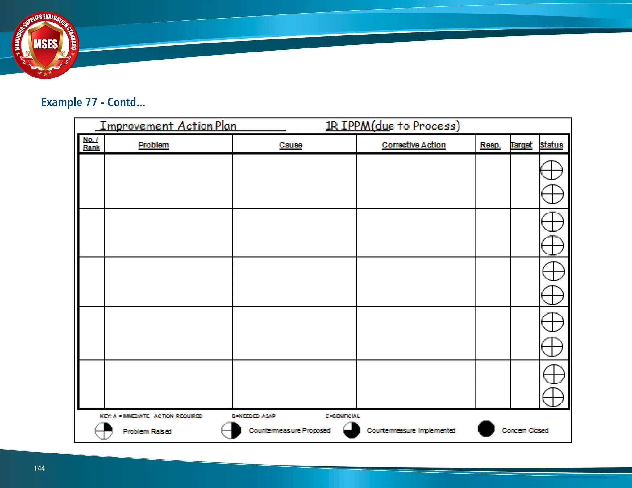
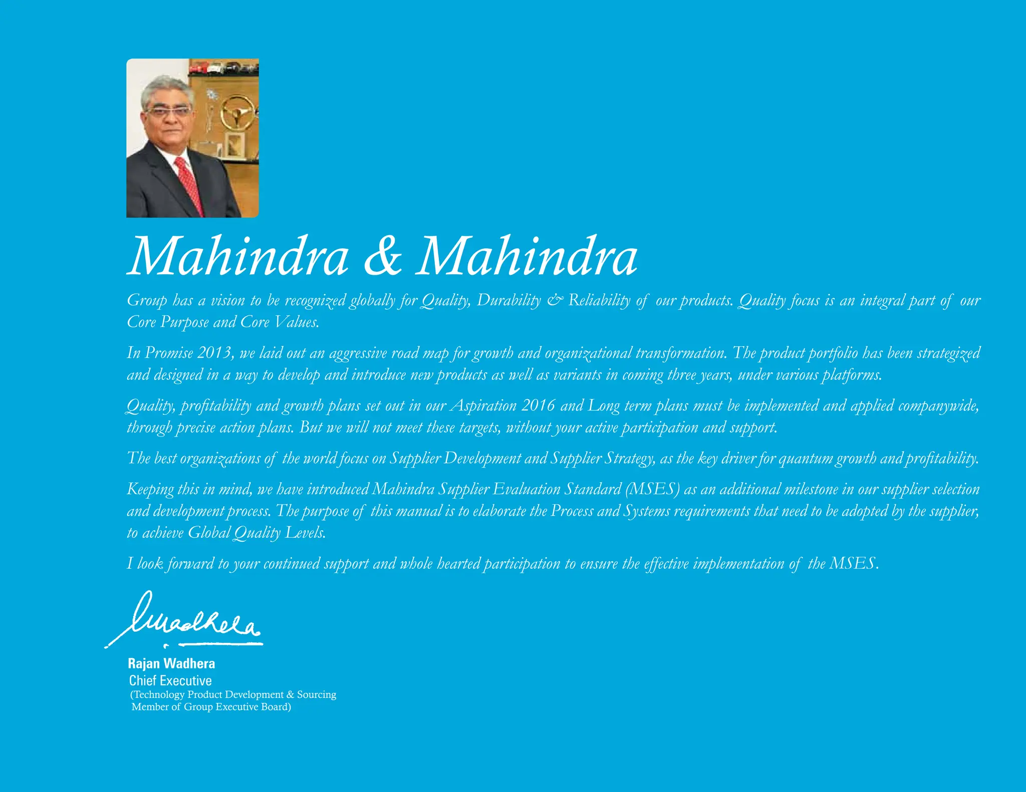
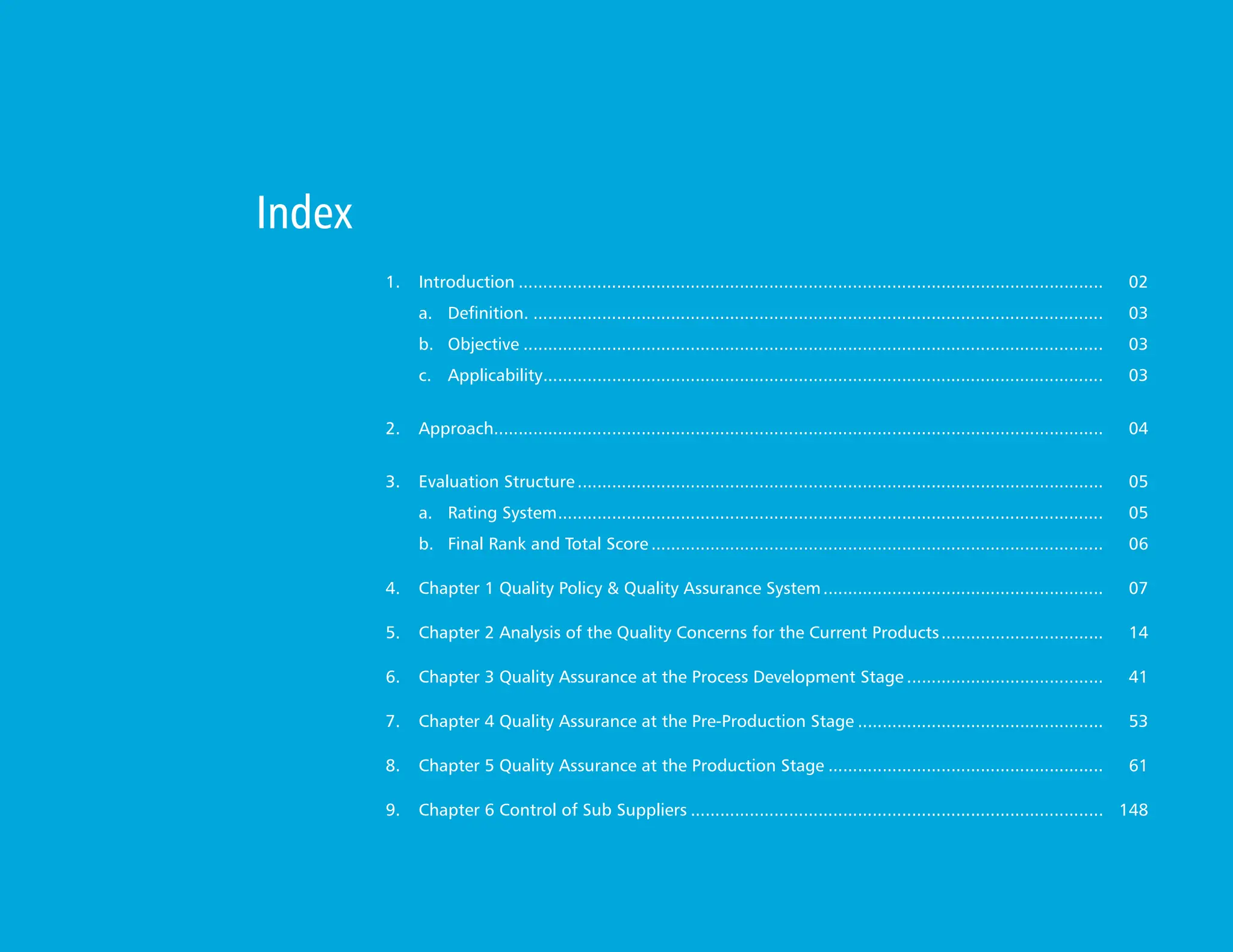
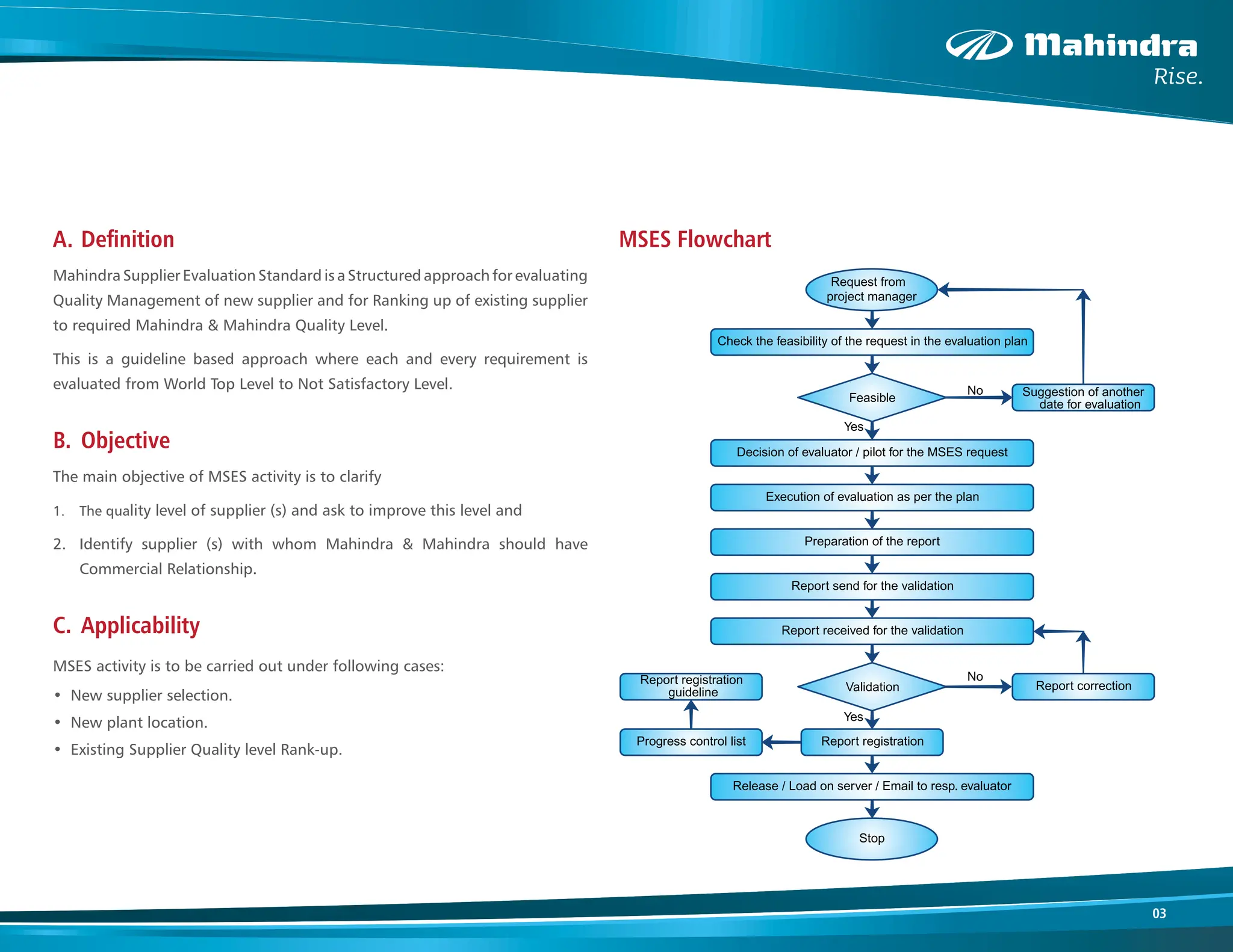
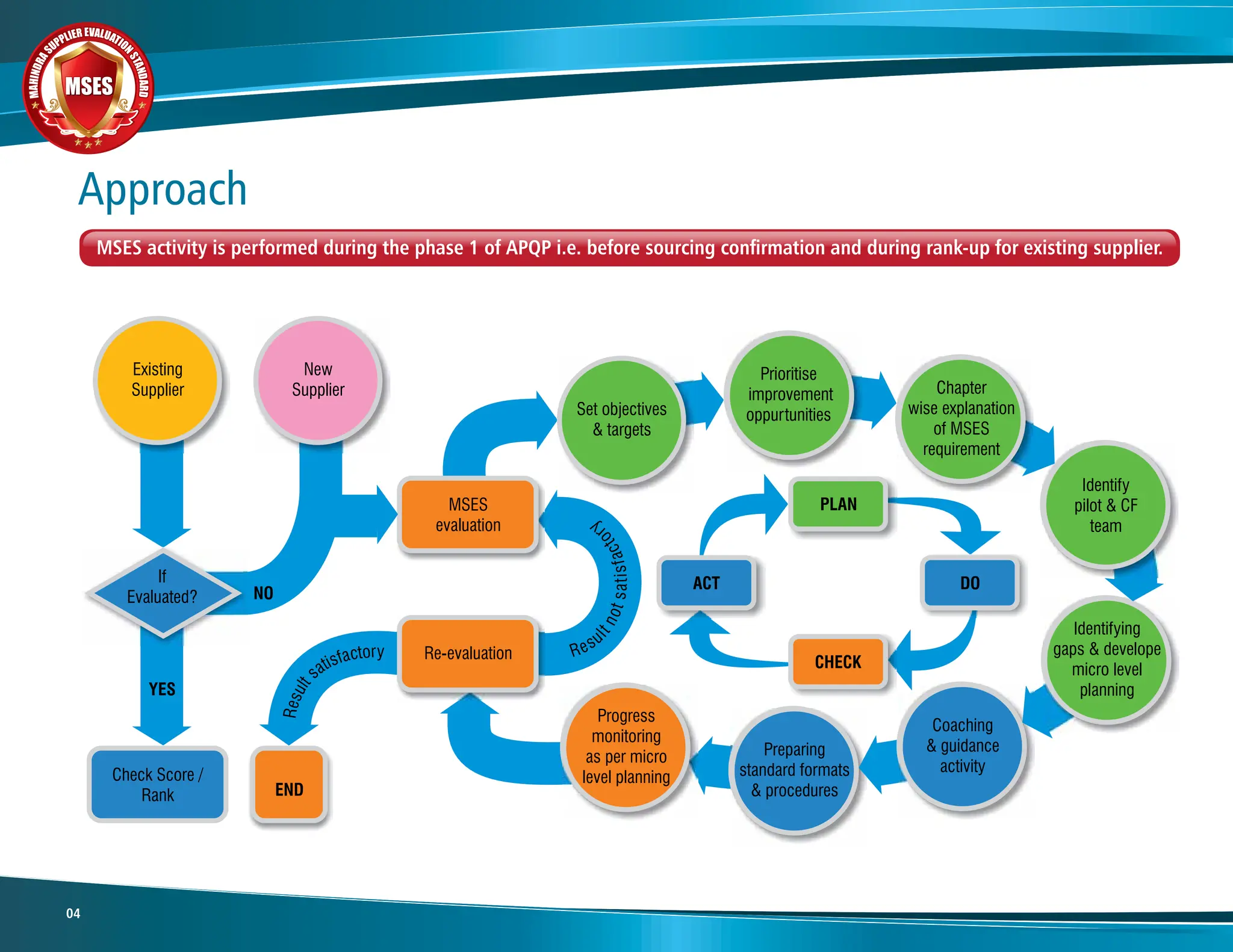
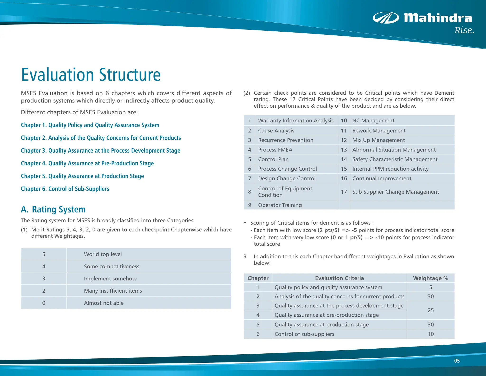
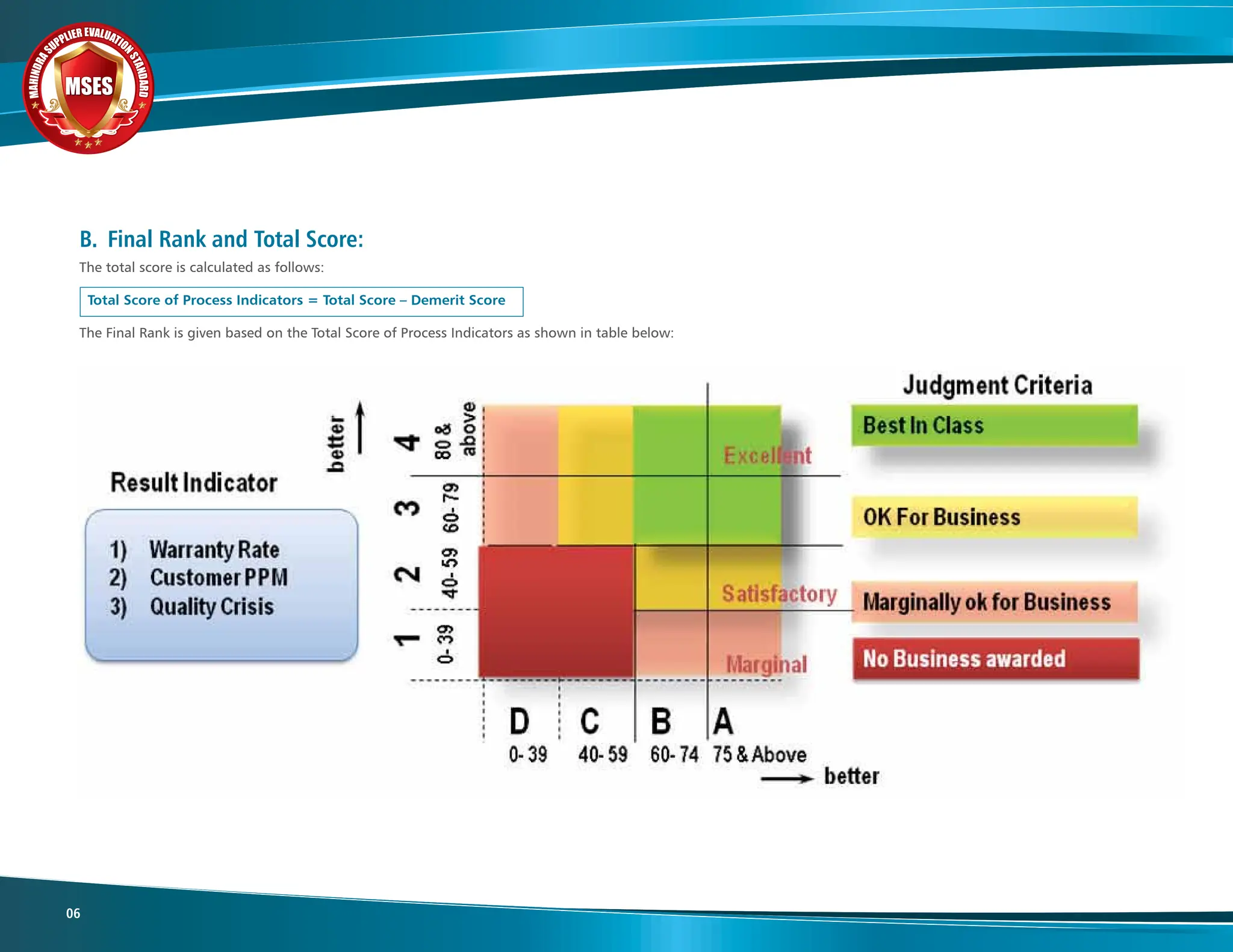
M
A
H
I
N
D
R
A
S
UPPLIER EVALUATIO
N
S
T
A
N
D
A
R
D
M
A
H
I
N
D
R
A
S
UPPLIER EVALUATIO
N
S
T
A
N
D
A
R
D
RANK-UP
RANK-UP
MSES
MSES
MSES
M
A
H
I
N
D
R
A
S
UPPLIER EVALUATIO
N
S
T
A
N
D
A
R
D
MSES
MSES
MSES
First Edition, May 2012
The information contained herein is an exclusive property of Mahindra & Mahindra Ltd. and shall not be distributed, reproduced, or disclosed in whole or in part without prior written permission of
Mahindra & Mahindra Ltd., failing which legal action can be initiated as per Jurisdiction of Mumbai. The content of this information is subjected to change without notice.
Rise by daring to disturb
the universe
ACCEPTING
NO LIMITS
Rise with your
ingenuity
CORE VALUES
• PROFESSIONALISM • GOOD CORPORATE CITIZENSHIP • CUSTOMER FIRST • QUALITY FOCUS • DIGNITY OF THE INDIVIDUAL
ALTERNATIVE
THINKING
Rise by shaping
destinies
DRIVING POSITIVE
CHANGE
Rise Culture - The House of Mahindra
Rajan Wadhera
Chief Executive
(Technology Product Development & Sourcing
Member of Group Executive Board)
Mahindra & Mahindra
Group has a vision to be recognized globally for Quality, Durability & Reliability of our products. Quality focus is an integral part of our
Core Purpose and Core Values.
In Promise 2013, we laid out an aggressive road map for growth and organizational transformation. The product portfolio has been strategized
and designed in a way to develop and introduce new products as well as variants in coming three years, under various platforms.
Quality, profitability and growth plans set out in our Aspiration 2016 and Long term plans must be implemented and applied companywide,
through precise action plans. But we will not meet these targets, without your active participation and support.
The best organizations of the world focus on Supplier Development and Supplier Strategy, as the key driver for quantum growth and profitability.
Keeping this in mind, we have introduced Mahindra Supplier Evaluation Standard (MSES) as an additional milestone in our supplier selection
and development process. The purpose of this manual is to elaborate the Process and Systems requirements that need to be adopted by the supplier,
to achieve Global Quality Levels.
I look forward to your continued support and whole hearted participation to ensure the effective implementation of the MSES.
Hemant Sikka
Head Sourcing (AFS)
Mahindra & Mahindra
We live and work in a hyper competitive world. Competing and winning in today’s global marketplace requires that our products and services
must be of high quality, developed with short lead times, delivered in right quantities and on time and at competitive cost.
This requires very robust processes and a strong commitment, led from the top, to quality delivery and continuous improvement.
We at M&M, have a firm belief that to achieve this goal, we must work closely with our suppliers as partners. We must have a process in place
that selects, supports and ensures our suppliers meet high quality requirements.
This has made it necessary for us to define the Quality expectation of Mahindra to our supplier partners, which have been formulated in the form
of Mahindra Supplier Evaluation Standard and Rank up manual.
The objective of this manual is to define the basic quality systems and process requirements that we expect our suppliers to follow to ensure that
our mutual responsibilites for product and service quality are understood and implemented.
We look forward to your complete understanding and support and believe that by working together we can develop a robust supply chain to achieve
world class quality and satisfy our customers needs.
1. Introduction........................................................................................................................ 02
a. Definition...................................................................................................................... 03
b.  	Objective....................................................................................................................... 03
c. Applicability.
.................................................................................................................. 03
2. Approach.
............................................................................................................................ 04
3. Evaluation Structure............................................................................................................ 05
a. Rating System.
............................................................................................................... 05
b. Final Rank and Total Score............................................................................................. 06
4. 	 Chapter 1 Quality Policy & Quality Assurance System.......................................................... 07
5. 	 Chapter 2 Analysis of the Quality Concerns for the Current Products.................................. 14
6. Chapter 3 Quality Assurance at the Process Development Stage......................................... 41
7. Chapter 4 Quality Assurance at the Pre-Production Stage................................................... 53
8. Chapter 5 Quality Assurance at the Production Stage......................................................... 61
9. 	 Chapter 6 Control of Sub Suppliers..................................................................................... 148
Index
M
A
H
I
N
D
R
A
SUPPLIER EVALUATIO
N
S
T
A
N
D
A
R
D
MSES
MSES
MSES
02
As a part of this strategy we have already introduced Global Benchmark
practice of Mass Manufacturing Approval during Start Of Production. This
has yielded highly successful Ramp Up in many of our key projects.
To further support our Endeavour to be Best in class for Quality Practices
there is a need to Next Mark the way we work.
In line with this we have introduced a Preventive approach which is Mahindra
Supplier Evaluation Standard termed MSES that outlines the detailed
requirements of Mahindra & Mahindra to establish a robust methodology in
Quality Assurance Management.
MSES is a structured Quality tool, that helps in establishing a robust quality
system which will guarantee Quality Systems, Development Planning, Concern
Management, Daily Work Management and Sub Supplier Management.
This ensures readiness of supplier in terms of quality & delivery requirements
of the customer during supplier selection, in case of new business and for
Ranking Up quality level of existing supplier.
The supplier is expected to Rank Up their existing Quality Systems in line with
this methodology.
This Manual is only for Reference.
The Automotive Industry in India is one of the largest in the world and one
of the fastest growing globally. India’s vehicle manufacturing industry is the
sixth largest in the world.
This has given rise to the challenges of creating World Class manufacturing
systems and World Class Supplier Base.
At Mahindra to meet these Challenges of the Industry we have adopted the
Philosophy of Rise which is Strong Foundation of Following Three Pillars.
These are strongly supported with quality as the main ingredient.
• Accepting No Limits
• Alternative Thinking
• Driving Positive Change.
We have established our own Quality way which is the MQW (Mahindra
Quality Way)
With this increasing demand it is imperative that we are able to achieve
World Class Quality levels in all areas of our operations including our supplier
development and management
We also strongly believe that the contribution of suppliers is key to the
growth of our business as we follow the philosophy of suppliers as partners
who need to have World Class quality Practices to meet this challenge.
Introduction
03
A. Definition
Mahindra Supplier Evaluation Standard is a Structured approach for evaluating
Quality Management of new supplier and for Ranking up of existing supplier
to required Mahindra & Mahindra Quality Level.
This is a guideline based approach where each and every requirement is
evaluated from World Top Level to Not Satisfactory Level.
B. Objective
The main objective of MSES activity is to clarify
1. The quality level of supplier (s) and ask to improve this level and
2. Identify supplier (s) with whom Mahindra & Mahindra should have
Commercial Relationship.
C. Applicability
MSES activity is to be carried out under following cases:
• New supplier selection.
• New plant location.
• Existing Supplier Quality level Rank-up.
MSES Flowchart
M
A
H
I
N
D
R
A
SUPPLIER EVALUATIO
N
S
T
A
N
D
A
R
D
MSES
MSES
MSES
04
Approach
MSES activity is performed during the phase 1 of APQP i.e. before sourcing confirmation and during rank-up for existing supplier.
05
Evaluation Structure
MSES Evaluation is based on 6 chapters which covers different aspects of
production systems which directly or indirectly affects product quality.
Different chapters of MSES Evaluation are:
Chapter 1. Quality Policy and Quality Assurance System
Chapter 2. Analysis of the Quality Concerns for Current Products
Chapter 3. Quality Assurance at the Process Development Stage
Chapter 4. Quality Assurance at Pre-Production Stage
Chapter 5. Quality Assurance at Production Stage
Chapter 6. Control of Sub-Suppliers
A. Rating System
The Rating system for MSES is broadly classified into three Categories
(1)		 Merit Ratings 5, 4, 3, 2, 0 are given to each checkpoint Chapterwise which have
different Weightages.
(2)		 Certain check points are considered to be Critical points which have Demerit
rating. These 17 Critical Points have been decided by considering their direct
effect on performance & quality of the product and are as below.
• Scoring of Critical items for demerit is as follows :
- Each item with low score (2 pts/5) => -5 points for process indicator total score
- Each item with very low score (0 or 1 pt/5) => -10 points for process indicator
total score
3		 In addition to this each Chapter has different weightages in Evaluation as shown
below:
5 World top level
4 Some competitiveness
3 Implement somehow
2 Many insufficient items
0 Almost not able
1 Warranty Information Analysis 10 NC Management
2 Cause Analysis 11 Rework Management
3 Recurrence Prevention 12 Mix Up Management
4 Process FMEA 13 Abnormal Situation Management
5 Control Plan 14 Safety Characteristic Management
6 Process Change Control 15 Internal PPM reduction activity
7 Design Change Control 16 Continual Improvement
8
Control of Equipment
Condition
17 Sub Supplier Change Management
9 Operator Training
Chapter Evaluation Criteria Weightage %
1 Quality policy and quality assurance system 5
2 Analysis of the quality concerns for current products 30
3 Quality assurance at the process development stage
25
4 Quality assurance at pre-production stage
5 Quality assurance at production stage 30
6 Control of sub-suppliers 10
M
A
H
I
N
D
R
A
SUPPLIER EVALUATIO
N
S
T
A
N
D
A
R
D
MSES
MSES
MSES
06
B. Final Rank and Total Score:
The total score is calculated as follows:
Total Score of Process Indicators = Total Score – Demerit Score
The Final Rank is given based on the Total Score of Process Indicators as shown in table below:
07
Chapter 1
Quality Policy & Quality Assurance System
PURPOSE
• To assure existence of Basic Quality System like ISO/TS.
• To assure methodology of Internal audit system is followed for Sustenance.
• To demonstrate ability in Maintaining Quality Systems.
REQUIREMENTS
• Availability of ISO/TS certification for the existing
plant.
• Availability of standard procedure for the Internal
system, process, & product Audit.
• Defined Plan & Frequency of internal system,
process, & product audit.
• Availability of specific Audit checklist for system,
process, & product.
• Audits should be conducted by Qualified & skilled auditors.
• Availability of reporting mechanism for Non Conformity.
• Methodology defined for deciding gravity of NC
(Major or Minor).
• Use of standard QC tools such as Why Why analysis
deployed to arrive at root cause.
• Availability of Non Conformity monitoring system
with open/close status.
• Conduct follow-up audit methodology to close the
NC.
• Quality award from Car Maker.
REFERENCES
• Internal audit procedure.
• Master list of business process (Apex manual).
• Audit Plan.
• Audit check sheet (Ex. 1).
• Audit report.
• NC Analysis Report (Ex 2).
• NC summary.
• List of internal auditors.
1.1 QA System
Objective: To ensure existence of Standard Working Processes and Methodologies for Sustenance of Day to Day activities.
M
A
H
I
N
D
R
A
SUPPLIER EVALUATIO
N
S
T
A
N
D
A
R
D
MSES
MSES
MSES
08
1 of 10
Doc No.
Rev No.
Process Name : Date :
Part No : Shift :
Part Description : Area : Incharge :
Customer : Machine No./ Name :
Operator :
ACCEPTANCE CRITERIA :
I – SYSTEM CHECKS
Weightage Points Score
(a) (b) (a x b)
1.1 I 0.5
1.2 I 0.5
1.3 I 0.5
1.4 I 0.5
1.5 I 0.5
1.6 I 0.5
2.1 I 0.5
2.2 I 0.5
2.3 I 0.5
2.4 I 0.5
2.5 M 1
Process & Product Audit Check Sheet
Is checklist for material receipt available & being followed?
CATEGORY :
M - Must
Strong Area
Weak Area Not meeting above requirement
Must score 50% in all sections
I - Important
Wrapping (To be completely covered with gunny bags)
Is there any wrong identification?
Sl
No
Is the prctice being followed as per control plan/ receiving inspection
standard ?
2 ) Raw Material/Storage (If Applicable)
Is the Raw material properly identified.
Is the area marked for keeping raw material.
Date
Are all products/ packages identified?
RATING CRITERIA :
If zero in M,score will be -5
If zero in VI,score will be -2
If zero in I,score will be -1
VI - Very Important
1 ) Incoming Packing Condition (If Applicable)
Any mix up?
Any dust or dirt?
Strapping (Three strap radially and one on the circumference).
Check Item Remarks
Result
Category
Any damage in package?
Example 1 - Audit Check sheet
Refer Annexure for Ex 1
09
Example 2 - N C Analysis Report
NON CONFORMITY REPORT
Doc No:
Rev No: 00
Rev date:
AUDIT SCHEDULE NO: REPORT NO: DATE:
AUDIT SDEPT/ AREA/ PROCESS: TIME : From ……………….
AUDITEE(s): AUDITOR(s):
Sl. No of Audit findings for which NC was sighted: Sign of AUDITEE
Sign of AUDITOR
Attribution to ISO-TS 16949 / ISO 140001 / OHSAS 18001:
NON CONFORMANCE / NEGATIVE OBSERVATION
ROOT CAUSE - (USE WHY - WHY ANALYSIS)
PROPOSED CORRECTIVE ACTION Target Date Responsibilit
y
DISPOSITION ACTION
FOLLOW UP AUDIT / VERIFICATION FOR IMPLEMENTATION (Write Observation)
VERIFICATION OF EFFECTIVENESS OF IMPLEMENTATION (Write Evidence )
VERIFIED BY MANAGEMENT REPRESENTATIVE
PROPOSED PREVENTIVE ACTION Target Date Responsibilit
y
DATE Auditor Sign
(use space overleaf if required)
Auditee Sign
Auditor Sign
NCR Status
Date
Sign. MR
Date
Contd...
A
A
M
A
H
I
N
D
R
A
SUPPLIER EVALUATIO
N
S
T
A
N
D
A
R
D
MSES
MSES
MSES
10
PURPOSE
• To assure mechanism of Quality Policy and Quality Objectives are defined in line with Company Indicators.
• To assure activity for deployment of these Objectives to Process, Product and Individual level is done.
REQUIREMENTS
• Availability of Specific Quality Policy signed by Top Management.
• Each element converted into Measurable & Quantifiable Objectives with clear
linkages to Quality Policy.
• Deployment of Quality targets based on past performance of the company and
plants.
• Company Objectives higher than all customer targets (LOI /CSR /CIR /SOR).
• Deployment of Objectives to process as well as product level on the shop floor.
• Relevant employees have been trained & understand the deployment of Objectives.
• Regular monitoring of target v/s actual.
• Should have Achieved objectives consistently for 3 years.
REFERENCES
• Quality Policy.
• Quality Objective / Business Plan / Balance Score Card / Simple Objective List.
• Customer Target Information.
• Target breakdown into product & process level (Ex 3).
• Data for target v/s actual.
1.2 Quality Objectives
11
Example 3 - Target Breakdown into Product & Process Level
S.NO AUG '10 SEPT'10 OCT'10 NOV '10 DEC'10
OBJECTIVE FOR
THE YEAR 2011
RESPONSIBILITY JAN'11 FEB '11 MAR'11 APR'11 MAY'11 JUN'11 JUL'11 AUG'11 SEP'11 OCT'11 NOV'11 DEC'11 AGGREGATE
1 100 120 80 90 60 50 0 50
2 0 0 0 0 0 0 0 0
3 0 0 0 0 0 60 0
4 157.8 89.77 81.91 93.03 74.89 75 64.85 76.9425
5 83.07% 86.61% 85.58% 85.38% 86.87% 88.00% 86.08% 0.8658175
LINE 1 3.39% 2.70% 0.86% 0.77% 1.14% 1.32% 0.71% 0.00985
LINE 2 4.64% 0.74% 0.78% 0.54% 0.16% 0.52% 0.61% 0.004575
ASSEMBLY 1.04% 0.40% 0.29% 0.05% 0.26% 0.33% 0.24% 0.0022
PAINTING 0.00% 0.00% 0.01% 0.00% 0.02% 0.00% 0.05% 0.000175
LINE 1 10.26% 6.47% 4.83% 4.79% 10.65% 4.46% 1.80% 0.05425
LINE 2 22.15% 2.48% 7.00% 4.61% 1.84% 5.92% 3.31% 0.0392
ASSEMBLY 5.11% 2.60% 1.20% 3.83% 2.70% 2.02% 1.11% 0.02415
PAINTING 6.54% 3.10% 3.56% 6.50% 4.27% 3.58% 4.98% 0.048325
8 0 0 1 1 0 0 0 0.25
9 10.56% 5.25% 2.83% 3.58% 4.25% 4.00% 3.00% 0.037075
10 4.2 6.6 6.5 6.9 5.8 12 10 8.675
11 68 272 160 0 496 800 224 380
OBJECTIVE FOR THE YEAR OF 2010-2011
MACHINE BREAKDOWN
PARTS / MANDAY
6
7
PARAMETER
INTERNAL QUALITY PPM
DELIVERY PPM
WARRANTY PPM
TRAINING HOURS
CONVERSION COST (Rs)
YIELD %
INTERNAL
REJECTION
INTERNAL
REWORK
ACCIDENTS
M
A
H
I
N
D
R
A
SUPPLIER EVALUATIO
N
S
T
A
N
D
A
R
D
MSES
MSES
MSES
12
PURPOSE
• To assure existence of QA organisation within the company, with clear Roles and Responsibilities defined for Quality Management.
• To assure mechanism of conducting Regular Quality Meeting.
REQUIREMENTS
• Availability of QA Organization including
functions such as development, in-process,
final inspection, customer, incoming, change
management, continuous improvement, and
safety characteristic.
• Defined Roles and Responsibilities of each
employee.
• Guideline to conduct Quality meeting
(Agenda, Frequency & Minutes).
• Attendance of Top management in Quality
meeting once per month.
• Recommendations from top management in case of delay or no achievement of
target.
• Take CSI from all plants of customer (SCM, MM, & SQA) and improve upon the
gaps.
REFERENCES
• QA organization chart (Ex 4).
• Roles & Responsibility document for QA.
• KRA/MOP Sheet.
• Quality Meeting Guideline.
• Quality Meeting Agenda, Minutes.
• CSI format.
1.3 QA System & Organization
13
Example 4 - QA Organisation Chart
HEAD Q A
Engineer - A
Operator
R M Inspection
Lab
Assistant
J E STD. ROOM
ORGANISATION LAYOUT CHART FOR QUALITY ASSURANCE DEPARTMENT
Engineer
………..
Inspectors 9
Inspectors
9
Helper
Helper
Engineer -B
Engineer -
Systems
J E Lab
1. P D I
2. Paint Shop Testing
3. Final Inspection
4. New Prod Quality
1. IMS Docs.
2. System Audit
3.Management
Review
4. Training
5. FMEA
6. Safety Audit
7. Liasoning
8. SPC
9. PPAP Approval
10. Change Control
1. Product
Audit, Dock
audit, layut
Inspection
2. Q I S
3. PokeYoke
1. Sample
collection &
Preparation.
2. Master &
representativ
e Sample
preparation
1. Process Audit
2. Product Audit
3. Supplier PPAP
4. Dock Audit
5. Layout inspn
6. Cust. Compl.
7. Rej handling
8. Problem solving
9. Safety
Charecteristics
10. Quality Meeting
1. Collection
of IMTEs
2. Servicing
of IMTEs
1. CFT, RFT,
Weld Tetsings,
BW testings, Salt
Spray, Wheel
Unbalance
Overall responsible for QA
& QS
1. Process Audit
2. Product Audit
3. Supplier PPAP
4. Dock Audit
5. Layout inspn
6. Cust. Compl.
7. Rej handling
8. Problem solving
9. Safety
Charecteristics
10. Quality Meeting
1. Calibration
of all IMT
2. External
Calibration
3. Standards
updation & MSA
1. Raw Material
Receiving
Inspection
1. CMM
Inspection of
:-
i. Product
ii. IMTE`s
M
A
H
I
N
D
R
A
SUPPLIER EVALUATIO
N
S
T
A
N
D
A
R
D
MSES
MSES
MSES
14
Chapter 2
Analysis of the Quality Concerns for the Current Products
REQUIREMENTS
• Availability of Warranty, Customer & In-house concern logbook / register / tracking
sheet.
• Availability of Monthly Monitoring trends for Warranty, Customer & In-house defects.
• Use of Pareto charts (By customer, by plant, by part, by defects etc ) to identify
Major contributors in case of Warranty , Delivery and In house defects.
• Mechanism for sharing these defects throughout the organization.
e.g. display of graphs at central location for tracking customerwise, monthwise,
partwise, defects / PPM.
• Defined the targets for Warranty, Customer PPM & In house PPM based on Past
1 year data.
• Defined 4M level Macro Action plan linked with organization Objective and
customer quality targets at the beginning of the Year based on this last year Quality
Performance data.
• Mechanism for monitoring the Progress of defined actions through Quality Review
Meeting.
• Defined Frequency of Quality Review Meeting (General – Monthly) and Plan as per
that frequency.
• Availability of All actions as a part of Progress Monitoring Sheet.
• Mechanism of Reviews for all earlier pending actions during Quality & Management
review MOM.
• Defined and Implemented recovery / revised action plan in case of any delay or non
achievement of target.
PURPOSE
• To assure that the targets are defined at the start of the year based on past performance.
• To assure that the targets are achieved by defining the action plan on prioritized problems and by monitoring the progress through structured
Quality concern reviews for warranty, Delivery and Internal defects.
2.1 Target Control
Objective: To ensure the Methodology of Defining and Monitoring the Progress of the actions to achieve the defined Targets
and Identifying the Real Root Causes by using Problem Solving Technique to avoid Recurrence of the problems.
REFERENCES
• Warranty Register, Customer PPM & In house PPM Register / Log book (Ex 5).
• Monthly monitoring trends, Pareto charts (Ex 6).
• Annual reduction Plan – 4M Level Macro Action plan and Monitoring(Ex 7).
• Quality Review Meeting Plan Vs Actual Status.
• Progress Control Sheet (Tracking Sheet) for Warranty, Delivery & Internal defects
(Ex 8).
15
Example 5 - Warranty Register
V1 Refer BMS for current revision level Page 1 of 1
Date: Reviewed By: Approved By:
WARRANTY/FIELD COMPLAINT REGISTER
Part
Name
Prod
Line
Dealer City Zone
Chasis
Mfg.
month
Month of
prodn./ unit
no.
Qty
S No. Customer
Date of
warr.
Recd.
Car
Model
Part
No.
New/Repeat/Rare
Concern
NTF/
DNR
Claim #
Dt
Before
break
point
After
break
point
Kms
Usage
Months
Defect
Des. by
customer
Claim
Accepted /
Rejected
Phenomena
found after
analysis
M
A
H
I
N
D
R
A
SUPPLIER EVALUATIO
N
S
T
A
N
D
A
R
D
MSES
MSES
MSES
16
Example 6 - Monthly Monitoring Trend, Pareto Chart
MONTHLY MONITORING TRENDS
17
Flange bWeld unde weld shift porosity 2008 0.48
0 0 0.14 0.003 Jan 09 0.24
Feb 09
Mar 09
Apr 09
May 09
Jun 09
Jul 09
Aug 09
Sep 09
Oct 09
Nov 09
Dec 09
2010
2011
1 2 3 4 5 6 7 8 9 10 11 12
0.1
0.1 Feb
0.1 Mar
0.1 Apr
0.1 May
0.1 Jun
0.1 Jul
0.1 Aug
0.1 Sep
0.1 0
0.1 0
0.1 0
0
0
0
0
0
0
0 0
0 0
0 0
0
0
0
0 0
0 0
0 0
0 0
0 0
0 0
0
0
0
0
0
0
1, Nozzle cleaning frequency to be defined in OS to
ensure gas flow.
Over all
2, Poka yoke for less gas flow to be introduced.
ACTION
0
0.039
0.475 0.33
0.05
0
0.008
0
FEB
0.24
0
JAN
0.003
0.14
0
0.005
0.05
0.04
0.04
0.01
0.02
0.02
0.005
REMARKS
0.03
0.02
0.02
0.02
0
0
BREAK DOWN OF TARGET
DEC
OCT NOV
AUG SEP
Flange bend
conveyor is shifted before conveyor i.e. immediately
after unloading.
2, An extra packing machine is installed to avoid
wheels waiting for packing
0
Weld undercut
Flange bend
Pin hole
Runout problem
Flange width variation
0.06
0.02
ASSEMBLY
Porosity
Weld shift
2009
2008
0.08
0.08
JUN
MAR APR JUL
MAY
Batch code damage
Weld short length 0.01
Material pitting 0.01
0.01
Grinding mark
0.115
0.005
0
0
0.115
0.01
0.01
Others
Weld undercut
Weld miss
time of setting
Weld shift
Effectiveness
Monitoring (month)
Responsibil
ity
PROBLEM
Porosity
round bar
1, Final wheel inspection table located after the
1, Setting parameters to be monitored & frozen
2. To have a master setting disc to set ESO at the
1. To replace sliding rail of AW - II with round bars
2. To device fastening arrangement according to
REJECTION TARGET - ASSEMBLY
107
100
75
40
35 32
28
21
16 15 12 12 12 10 10 9 8 8 7 7 6 6 6
34
0
20
40
60
80
100
120
0
20
40
60
80
100
120
Porosity
weld
shift
weld
undercut
Flange
bend
Weld
problem
Pin
hole
Runout
problem
Dimension
problem
Batch
code
…
Weld
short
length
Grinding
mark
Material
pitting
Weld
miss
Thin
down
Trim
line
Power
cut
rej.
Due
rework
Scuffing
mark
Hub
Crack
Over
bead
Trial
(MIG
weld)
Dent
Disc
problem
Others
REJECTION ASSEMBLY - YTD
REJECTION = 0.47%
0.475
0.24
0
0.1
0.2
0.3
0.4
0.5
0.6
0.7
0.8
0.9
1
2008
Jan
09
Feb
09
Mar
09
Apr
09
May
09
Jun
09
Jul
09
Aug
09
Sep
09
Oct
09
Nov
09
Dec
09
2010
2011
%
Rejection
TARGET - ASSEMBLY (REJECTION)
0.33%
0.27%
0.21%
0.003
0
0.01
0.02
0.03
0.04
0.05
0.06
Jan 09 Feb 09 Mar 09 Apr 09 May
09
Jun 09 Jul 09 Aug 09Sep 09 Oct 09 Nov 09Dec 09
Porosity
0.14
0
0.02
0.04
0.06
0.08
0.1
0.12
0.14
0.16
Jan 09 Feb 09 Mar 09 Apr 09 May
09
Jun 09 Jul 09 Aug 09Sep 09 Oct 09 Nov 09Dec 09
Weld shift
0
0
0.005
0.01
0.015
0.02
0.025
0.03
0.035
0.04
0.045
Jan 09 Feb 09 Mar 09 Apr 09 May
09
Jun 09 Jul 09 Aug 09Sep 09 Oct 09 Nov 09Dec 09
Weld undercut
0
0
0.005
0.01
0.015
0.02
0.025
Jan 09 Feb 09 Mar 09 Apr 09 May
09
Jun 09 Jul 09 Aug 09Sep 09 Oct 09 Nov 09Dec 09
Flange bend
OWN TARGET
Doc No :
Rev No :
Date :
Target
Actual
Example 7 - 4M Reduction Plan Global Targets - Rejection
M
A
H
I
N
D
R
A
SUPPLIER EVALUATIO
N
S
T
A
N
D
A
R
D
MSES
MSES
MSES
18
Example 8 - Progress Control Sheet for Warranty. Delivery & Internal Defects
Doc No.
Rev No.
DATE
Plan Actual Plan Actual Plan Actual Plan Actual Plan Actual Plan Actual PFC
Control
plan
FMEA WI OS SIR
Set up
verificati
Start up
checklis
Alarm
level
PTD
Technic
al know
1 QD/11/01 Flange width variation 03.01.11 11.01.11 New P 03.01.11 03.01.11 03.01.11 03.01.11 10.01.11 06.01.11 17.01.11 11.01.11 17.01.11 11.01.11 17.04.11 P P 03.01.11
2 QD/11/02 Vent hole pierced at wrong location 05.01.11 10.01.11 New - NA NA NA NA 12.01.11 06.01.11 19.01.11 06.01.11 NA NA NA NA P 05.01.11
3 QD/11/03 Weld crack 05.01.11 New - NA NA NA NA P 05.01.11
4 QD/11/04 Band overlap 05.01.11 24.01.11 New - NA NA NA NA 12.01.11 07.01.11 19.01.11 24.01.11 19.01.11 24.01.11 19.04.11 P P 05.01.11
5 QD/11/05 Flange bend 05.01.11 19.01.11 New P NA NA NA NA 12.01.11 08.01.11 19.01.11 17.01.11 NA NA NA NA P 05.01.11
6 QD/11/06 Band bulged 05.01.11 12.01.11 New - NA NA NA NA 12.01.11 08.01.11 19.01.11 10.01.11 19.01.11 10.01.11 19.04.11 P P 05.01.11
7 QD/11/07 Weld shift 05.01.11 15.01.11 New - NA NA NA NA 12.01.11 05.01.11 19.01.11 17.01.11 19.01.11 17.01.11 19.04.11 P 05.01.11 30.01.11
8 QD/11/08 Air pocket 05.01.11 31.01.11 New P NA NA NA NA 12.01.11 12.01.11 19.01.11 23.01.11 NA NA NA NA 001 P P 05.01.11 30.01.11
Interim action
QUALITY CONCERNS PROGRESS CONTROL SHEET
Under progress
Closed
on
Documents Updation (Please put date when activity completed)
Root cause
analysis
Horizontal
deployment
Responsibi
lity
Target
Date
Problem
New or
Repeat
Quality
Alert
Preventive action
S.No
.
QPCR /
8D No.
Concern Description
Raised
on
Emergency
Response
Change
control
no.
Corrective action
19
PURPOSE
• To assure the System of Proactive collection and recording of Warranty Information with defined details.
• To establish the mechanism of Monitoring the Alarm indicators and take actions in case of Alarm level is reached.
• To assure the Information Analysis on defined elements ( like Production month , Kms etc ) and also in case of rare claims detailed analysis is available.
REQUIREMENTS
• Defined Frequency and Responsibility to collect
Warranty Information (Proactively).
• Defined mechanism to collect Warranty raw data
with required details (Mfg. date, Sale date , vehicle
no, area, dealer, region, KM, Mfg. traceability, chassis,
model, problem description, whether parts replaced,
etc.).
• Mechanism of defining alarm controls and taking
actions in case of alarm is reached.
• Defined specific alarm control for Safety parts.
• Availability of a standard procedure for information
analysis which describes analysis steps and parameters
like Production Month, reported month, dealer, Kms etc.
• Use of Information Analysis is done for each defined item.
• Mechanism of tracking the Progress of actions for rare claims through a Progress
Control Sheet (Tracking sheet).
• Availability of Cause Analysis for Occurrence and non-detection for all the defects.
2.2 Information Analysis
REFERENCES
• Warranty Information Analysis procedure with defined Responsibility and Frequency
to collect the information (Ex 9A, Ex 9B).
• Warranty Information Register (Refer Ex 5).
• Warranty Information Analysis monthly (Ex 10).
• Detailed cause analysis for rare claims.
• Monitoring of Alarm controls which is predefined for elements (like Kms, Dealer,
region, Model etc.) with recovery action plan.
• Progress Control Sheet for rare claims to track the progress on actions.
M
A
H
I
N
D
R
A
SUPPLIER EVALUATIO
N
S
T
A
N
D
A
R
D
MSES
MSES
MSES
20
Example 9A - Warranty Information Analysis Procedure
Refer Annexure for Ex 9A
Procedure No
Page No
Page issue No
Issue date
Signature
Input Where Output When Who
Joint analysis report Plant Warranty log After initial analysis QA
PROCEDURE FOR WARRANTY HANDLING
TITLE :- WARRANTY HANDLING
What How
QA email / phonecall
Customer given samples
Conduct the data analysis and the preliminary joint analysis (
Visual inspection & feel) with the customer at warranty cell and
decide
a) Accept claim - Confirmed by visual inspection
b) Accept claim - needs further investigation at plant
c) Reject claim
Warranty cell
Joint analysis report &
Parts accepted /
rejected
As per customer's
requirement/monthly
QA/ Marketing Joint analysis format.
d) New claim
---
Receipt of the warranty complaint from the customer through
Telephone call / Warranty analysis meeting
Attend the Warranty
meeting at customer
end.
(1)TKML :- Once/month.
Other customer email
monthly to get data or nil
rejection from customer.
Warranty formats
As per customer's
requirement/monthly
e) Rare claim
Claim accept -a) The part in which defect is confirmed is sent to
scrap yard
b) Carryout Testing like Axial play & torque ,Push out & pullout
,Dimesional in plant standard room for the parts in which defect
is not evident.
Warranty log
Customer given samples Claim Reject : Reject claim and handover parts to customer Warranty cell NTF records After Initial analysis QA
Joint analysis report with
customer.
Analysis report
Customer given samples
Claim for Old cases (Whose actions are completed).Verify the
failure mode by visual / dimensional / metallurgical inspection Plant
Observations after
After initial analysis QA
START
21
Example 9B - Warranty Assessment Flow Chart
SCOPE: Applicable for all Warranty.
Responsibility : Customer Representative/Marketing/PD
Immediately after occurred
Onces in a month
Yes
Two working day
Pareto analysis graphs updated
Data to be captured - Modelwise trend
- Vehicle model Project Manager /Engg.. - Kilometerwise trend
- Vehicel chassis(Sl.no) - Dealerwise trend
- Vehicle manufacturing / sale date - Phenomenon trend
- Vehicle defect report date(Claim Date) - Defect Wise trend
- Defect / Problem reported Yes - Aditya Production batch wise
- Dealer details (name, location) Start of year. - Location/ Zone wise trend( N,E,W,S)
- Production code of Aditya - Defect compared to sale date trend
-Aditya label / pad print details( If Applicable) - Warranty cost trend
QA/Engg/NPD
Receive the data( market Claim) for compilation
Compiled data
Data for trend analysis captured in Format
No.AAP/WGF/00/00 . & AAP/WF/01/00
QA/PD/Aditya Reps..
If no warranty information is received from customer
end, Aditya respresentative at Customer End will visit
the Customer place & collect the Information on
monthly basis or as per the customer practice.
- Conform the Warranty Information through Email &
update the the Warranty data for the month.
Receive warranty information (
market Claim)from customer
through our representative by
website, mail, fax, phone or
letter (or) returned part.
Process Output
WARRANTY ASSESSMENT PROCEDURE
Doc No. :
Org Date :
PURPOSE: To establish a documented procedure to ensure that the Product that does not conform to specified requirements are prevented from
unintended use/Before Warranty period From end user .
Input
Page No: 1 Of 3
Title: Warranty Assessment (Information collection, trend analysis & feedback to
customer)
Rev/date :
Forward this to QA / Production / Engg. /
Maintenance / Purchase.
QA /Project Manager /Engg..
Update the data production monthly wise in the format
(AAP/WF/01/00 ) .
Fix Targets for the current year with
Reduction percentage and Decide the
Focuse areas for Problem Solving Viz,
Compiled date and
make Trend/ parato
analysis
-Aditya label / pad print details( If Applicable) - Warranty cost trend
- Kilometers covered - claim monthwise
- Location/ Zone wise trend( N,E,W,S)
- Cost of warranty onces in year & ever month
- Customer PPM
Yes
Forward to QA, Operation, Production, ME &
Purchase & give the feed back as per
procedure 14 P 01 00 C
Alarm Conditions are
- New Defect
- Defect after the action Taken
- Zone Wise Defect in %
- Delear Wise Defect in % Project Manager /Engg..
Focuse areas for Problem Solving Viz,
Production Month wise Defects, Claim
Month Wise Defects, customer Zone Wise
Defects, Product Wise Defects etc.
A
M
A
H
I
N
D
R
A
SUPPLIER EVALUATIO
N
S
T
A
N
D
A
R
D
MSES
MSES
MSES
22
Two working day
Pareto analysis graphs updated
Data to be captured - Modelwise trend
- Vehicle model Project Manager /Engg.. - Kilometerwise trend
- Vehicel chassis(Sl.no) - Dealerwise trend
- Vehicle manufacturing / sale date - Phenomenon trend
- Vehicle defect report date(Claim Date) - Defect Wise trend
- Defect / Problem reported Yes - Aditya Production batch wise
- Dealer details (name, location) Start of year. - Location/ Zone wise trend( N,E,W,S)
- Production code of Aditya - Defect compared to sale date trend
-Aditya label / pad print details( If Applicable) - Warranty cost trend
QA /Project Manager /Engg..
Update the data production monthly wise in the format
(AAP/WF/01/00 ) .
Fix Targets for the current year with
Reduction percentage and Decide the
Focuse areas for Problem Solving Viz,
Compiled date and
make Trend/ parato
analysis
-Aditya label / pad print details( If Applicable) - Warranty cost trend
- Kilometers covered - claim monthwise
- Location/ Zone wise trend( N,E,W,S)
- Cost of warranty onces in year & ever month
- Customer PPM
Yes
Every month
NO
Yes
Prepared by : Approved by :
Ammendment details:
PG PT
A/F
1 ------ 00/06.06.09 nil 00/06.06.09 ---- -----
2
Sl
No.
ISSUE NO & DT REV NO & DT
A/F
B/F B/F NO NO
New Release New Release
Reason for change Changed By
Details of change
Forward to QA, Operation, Production, ME &
Purchase & give the feed back as per
procedure 14 P 01 00 C
Alarm Conditions are
- New Defect
- Defect after the action Taken
- Zone Wise Defect in %
- Delear Wise Defect in %
- 0- 1000 Km range
Project Manager /Engg..
Check for the Alarm Conditions / update the trend
graph.
Beyond
Alarm
Conditions
Project Manager /Engg..
.
Analysis wide Customer input and Warranty analysis
Procedure (14 P 01 00 C)
Focuse areas for Problem Solving Viz,
Production Month wise Defects, Claim
Month Wise Defects, customer Zone Wise
Defects, Product Wise Defects etc.
Below the Alarm control Action to be
taken based on the CFT review ( Focused &
Priority area action will be taken for CAPA .
Contd... A
23
Example 10 - Warranty Information Analysis Monthy
Trend graphs : MODLE FORMAT
Prodn month
produced
quantity
Claims Defect PPM
Mar'10 9
Defect Qty
Center locking defective 5
FRE ECU 0 Not Open From Inside 5
FRM 6 not working 22
Back Manual 1 outside not releasing 4
170N back 0
FLE 2
RLE 0
Back ele w/o irc 3
Back ele 3
RLE 2 TOTAL 36
RLM 1
RRM 1
FRE nippon 11
FRE 1500N 0 Phenomenon trend
20N back 0 Actuator signal not passing 2
10N back 0 Actuator noise 4
RRE 3 ouside release free play 3
FLM 3 Found ok 22
950N back 0 Latch damage can,t able to analyse 5
210N back 0
141N back 0
200N back 0 TOTAL 36
FRE 0
FRE 950N 0
RRE 0
RLM 0
FRM 0
TOTAL 36
25 K to 50 K 7
10 K to 25 K 12 North 20
5 K to 10 K 4 West 6
NO TAG 2 South 4
0 to 1K 7 East 2
1 K to 5 K 4 Central 4
50 K to 75 K 0 north east
75K to 100 K 0
FRM 1520.04 0 to 3 7
Total 36 Back Manual 242.27 4 to 6 10
FLE 709.41 7 to 9 2
Back ele w/o irc 1828.08 10 to 12 4
Back ele 1977.81 13 to 15 4
Defects Qty % Cum. % RLE 1268.88 16 to 18 1
Not Working 19 52.8 52.8 RLM 271.95 19 to 21 1
Not Open From Inside 4 11.1 63.9 RRM 271.95 22 to 24 2
nor open from outside 8 22.2 86.1 FRE nippon 13879.58 After 2Yrs 5
not lock by remote 5 13.9 100.0 RRE 1903.32 Total 36
0.0 100.0 FLM 760.02
0.0 100.0
0.0 100.0
0.0 100.0
0.0 100.0 Total 24633
Total 36
Cai Industries 1
Dehradun Premier 1
DPC Motors 1
Garapati Autoventures 1
Global Gallarie 4
India Garage 1
JS Fourwheel 1
Koncept Automobiles 1
KS motors 3
MPL Automobiles 1
Conclusion: 11% of rejections has been claimed by the Dealer dehradum premier Visit Dealer Appropriately. If any Dealer causing Warranty Claim more than
10% is considered as Alarm Condition.
Zone wise trend
Conclusion: Considering the Top 3 Dealer's from a
particular Zone contributing Warranty claims more
than 10% of the total is considered as Alarm Cond
& necessary action will be taken.
Warranty Trend Analysis of March'11
Doc No. : Org Date :
Page No: 1 Off 3 Rev/date :
Warranty Cost
Defect to Production batch - trend
Conclusion: From the Graph FRM has highest
Warranty Claim & is considered for Analysis
Note: Warranty Target cannot be fixed because:
1. Based on production batch: There are 25 models
& production Qty will vary for every model in every
month. Data/ claims available from Sep'09 whereas
production batch varies from Year 2008-10.
2. Based on Warranty PPM Target fixed: Target fixed
in PPM but the data available in Qty & PPM cannot
be calculated.
Defect wise trend
Conclusion: Prioritise the Defects for which
Actions to be taken by plotting the Pareto Graph.
Take Corrective & Preventive Action for Horizantol
deployment of all the Defects.
Note:
1. For each & every defect/ phenomena we are
plotting the Pareto & taking Corrective actions for
all the problems.
2. If the warranty is claimed after CAPA
Implementation date then it is considered as Alarm
condition & necessary action will be taken.
Model trend
Kilometerwise trend
Conclusion: 50% of rejections have failed in b/w
25K-50K Kms Range.
27% of rejections have failed in b/w 25k to 50k Kms
Note:
1. Warranty Claims less than 1000Kms is considered
as Alarm Condition & actions will be taken for the
same.
2. Warranty target could be fixed based on
percentage but it is not the appropriate method.
MIS Trend
Monthly Defect wise Pareto Graph
Dealerwise trend
5 5
22
4
0
5
10
15
20
25
20
6
4
2
4
0
5
10
15
20
25
North West South East Central north
east
2
4
3
22
5
0
5
10
15
20
25
1 2 3 4 5 6 7
4
3
2 2 2 2
3
2.5
3
3.5
4
4.5
0
2
4
6
8
10
12
14
1 2 3 4 5 6 7 8 9 10 11 12 13
Alarm
Condition
0
6
1
0
2
0
3 3
2
1 1
11
0 0 0
3 3
0 0 0 0 0 0 0 0 0
0
2
4
6
8
10
12
19
4
8
5
0.0
20.0
40.0
60.0
80.0
100.0
120.0
0
2
4
6
8
10
12
14
16
18
20
Pareto for Supplier Rejections
%
Cumulative
Qty
0
0
0
0
0
0
0
0
0
0
0
2000
4000
6000
8000
10000
12000
14000
16000
7
10
2
4 4
1 1
2
5
0
2
4
6
8
10
12
0 to
3
4 to
6
7 to
9
10
to
12
13
to
15
16
to
18
19
to
21
22
to
24
After
2Yrs
A
M
A
H
I
N
D
R
A
SUPPLIER EVALUATIO
N
S
T
A
N
D
A
R
D
MSES
MSES
MSES
24
Back ele 1977.81 13 to 15 4
Defects Qty % Cum. % RLE 1268.88 16 to 18 1
Not Working 19 52.8 52.8 RLM 271.95 19 to 21 1
Not Open From Inside 4 11.1 63.9 RRM 271.95 22 to 24 2
nor open from outside 8 22.2 86.1 FRE nippon 13879.58 After 2Yrs 5
not lock by remote 5 13.9 100.0 RRE 1903.32 Total 36
0.0 100.0 FLM 760.02
0.0 100.0
0.0 100.0
0.0 100.0
0.0 100.0 Total 24633
Total 36
Cai Industries 1
Dehradun Premier 1
DPC Motors 1
Garapati Autoventures 1
Global Gallarie 4
India Garage 1
JS Fourwheel 1
Koncept Automobiles 1
KS motors 3
MPL Automobiles 1
Narain Automobiles 2
Nataraj Mobiles 1 0.111111111
NO tag 2
Patwa Automobiles 2
Pratik Automobiles 2
Provincial Automobiles 1
Royal Automobiles 1
Sablok cars 1
Silver Jublee 1
Sri durga 1
Sterling Motor 3
Tirupati Automobiles 1
Trendy Wheels 1
Tvs Sundram 1
United Automobiles 1
Total 36
Problem Description
Mar-08 Apr-08 May-08 Jun-08 Jul-08 Aug-08 Sep-08 Oct-08 Nov-08 Dec-08 Jan-09 Feb-09 Mar-09 Apr-09 May-09 Jun-09 Jul-09 Aug-09 Sep-09 Oct-09 Nov-09 Dec-09 Jan-10 Year'07/Blanks/Year'00/Year'04 Total
Found ok 1 1 1 1 1 1 2 14 22
Actuator Failure 1 1 1 3
Actuator soldering missing 1 1 2
Actuator working noise 0
Clow singal unlock From both side 2 3
Inside release lever stuck 1 1
Outside not open 1 1
Not opening by key 2 2
Blanks 1 1
Lock lever broken 0 0
TOTAL 0 1 0 0 0 0 0 0 0 1 0 0 1 2 1 1 0 2 0 2 1 4 0 18 34
Ammendment details:
DT PG PT
Conclusion: 11% of rejections has been claimed by the Dealer dehradum premier Visit Dealer Appropriately. If any Dealer causing Warranty Claim more than
10% is considered as Alarm Condition.
MANUFACTURED MONTH
Sl No.
ISSUE NO & DT
Monthly Defect wise Pareto Graph
Dealerwise trend
Details of change Reason for change Changed By
A/F
B/F B/F A/F NO NO
1 1 1 1
4
1 1 1
3
1
2
1
2 2 2
1 1 1 1 1
3
1 1 1 1
0
0.5
1
1.5
2
2.5
3
3.5
4
4.5
19
4
8
5
0.0
20.0
40.0
60.0
80.0
100.0
120.0
0
2
4
6
8
10
12
14
16
18
20
Pareto for Supplier Rejections
%
Cumulative
Qty
0
0
0
0
0
0
0
0
0
0
0
2000
4000
6000
8000
10000
7
2
4 4
1 1
2
5
0
2
4
6
8
0 to
3
4 to
6
7 to
9
10
to
12
13
to
15
16
to
18
19
to
21
22
to
24
After
2Yrs
0
5
10
15
20
25
30
35
40
1 2 3 4 5 6 7 8 9 10 11 12 13 14 15 16 17 18 19 20 21 22 23 24 25
Lock lever broken
Blanks
Not opening by key
Outside not open
Inside release lever stuck
Clow singal unlock From both side
Actuator working noise
Actuator soldering missing
Actuator Failure
Found ok
Contd... A
25
2.3 Cause Analysis of Returned Parts (Sequence should be Warranty, Delivery and In-House Defects)
PURPOSE
• To assure the System of Proactive collection and analyzing of Warranty & Delivery returned parts.
• To ensure the use of Detailed Cause Analysis / problem solving technique to identify the real Root Cause for Customer & In House complaints.
• To assure the Analysis of NTF concerns.
REQUIREMENTS
• Defined frequency to collect Warranty
& Customer returned parts.
• Mechanism to make analysis with
defined frequency for Warranty
& Delivery (Warranty - monthly /
customer PPM - monthly).
• Defined Standard procedure for Root
Cause Analysis. (Non detection &
occurrence, cause validations)
• Use of such defined guideline for
analysis of warranty PPM (all defects),
Customer PPM (all defects & Internal
Concerns major contributors.
• Availability of Targets Set for NTF or DNR reduction and Monthly Monitoring with
action plan in case of non achievement.
• Availability of part wise or commodity wise Dos & Don’ts signed off with customer.
• Defined agenda for Line Visit.
• Availability of Customer line verification plan and actual status.
• Defined and applied analysis method by Phenomenon (for assembly / system
related defects) / Master Ishikawa for Part level, and its application.
REFERENCES
• Cause Analysis procedure (Ex 11A).
• Cause Analysis Flowchart (Ex 11B).
• Detail Root Cause Analysis report (eg. 8D) for Warranty, Customer & Internal
concerns (Ex 12).
• Phenomenon wise analysis Flow Chart (Ex 13).
• Approved recommendation sheet (by Customer SCM / STA & buyer) with Dos &
Don’ts (Ex 14).
• Customer Line Verification Plan (Ex 15).
• Customer line verification Check Sheet and Agenda for visit (Ex 16).
• NTF & DNR Target , Monitoring sheet with action plan to reduce the same (Ex 17).
• Master Ishikawa for Part level Repetitive concerns (Ex 18).
M
A
H
I
N
D
R
A
SUPPLIER EVALUATIO
N
S
T
A
N
D
A
R
D
MSES
MSES
MSES
26
Example 11A - Cause Anaysis Procedure
Refer Annexure for Ex 11A
SOP
CAUSE ANAYSIS PROCEDURE SOP
Date
Page
Rev No 04
CAUSE ANAYSIS PROCEDURE
PROCESS APPROACH FOR ANALYSIS OF PROD/PROCESS PROBLEMS & INITIATION OF CORRECTIVE & PREVENTIVE ACTIONS
TS CLAUSE NO. 8.4, 8.5.2, 8.5.2.1, 8.5.2.2 , 8.5.2.3, 8.5.2.4 & 8.5.3 ISO 14001 CLAUSE NO. 4.5.3
Rev. No. 04
1 PURPOSE
To establish and maintain a system for taking corrective and preventive actions
2 SCOPE
To establish and maintain a system for taking corrective and preventive actions.
Applicable to Customer return , warranty return , as well as inhouse rejections ( Monthly Basis) .
3
3.1 Head quality assurance is overall responsible for implementation of this process approach.
3 2 R i i i h ibl f i l i f h i di d d id d b CFT/
PROCESS OWNER
3.2 Respective section incharges are responsible for implementing of the immediate and permanent countermeasures decided by CFT/ team.
3.3 Respective section incharges are responsible for analyzing the potential non-conformances with concerned CFT and submit the countermeasure report to head quality assurance.
3.4 Other specific responsibilities are as given in the procedure by means of flow chart.
4
Doc.No. Location
Description Retention Period Responsibility Method Of Disposal
Quality Records
F07-8204 Defined place
F02-7103 Defined place
5
Action plan Current financial year+1 year back Relavent sec.head Sale to scrapper
DEFINITION
Defect information cum countermeasure report Current financial year+1 year back Relavent sec.head Sale to scrapper
5
CFT Cross functional team IN HO In House
QC Quality control CL Customer Line
Activity responsible department WR Warranty Return.
DEFINITION
FMEA Failure mode effect analysis
OCI Operation control instruction
CFT Cross functional team IN-HO In-House.
QA Quality assurance
6
R ibilit F
P f i di t R l t T Q/E D t il f P f I di t R f D u t
CP Control plan
Effectiveness & Efficiency Indicators /Performance Indicators
p
Responsibility Frequency
Monthly
Monthly
Performance indicators Relavent To Q/E Detail of Performance Indicators Reference Documents
Effectiveness Q
No.of fool proofing done in the process Respective
incharge
Summary of poka-yoke
No.of preventive actions taken DICR reports
y
7
Q-Quality Management System Requirement , E-EMS Requirement
REFERENCES
8 AMENDMENT RECORD
----------
------------
8
Amd By Approved By
AMENDMENT RECORD
Amendment Date Amd No Amd Details Reason For Amd
04.01.10 03 Nill Periodical Review Bhupendar MR
27
Example 11B - Cause Analysis Flow Chart
SOP
Date
Page
Rev. No.
QA Pur Engg Prod PPC Sales CFT All
1 CFT .
customer line complaints/ in-
house mothly top 2 issues
based on pareto / Warranty
Complaints.
Using QC tools through
DICAR
Customer end & In
house at relavent
stages.
As & when complaint
received from customer &
For inhouse , take a major
rejections monthly once.
To resolve the
issue
F07-8204 ----------
2 CFT Defect details.
1.Implement the 100 %
inspection/ Prepare one point
lesson / Work instructions
for prevent the output flow
2.Implement Error Proofing
(or) kaizen for prevent the
occurrence.
At relavent stage
Within 12 hrs of defect
noticed
To resolve the
issue
F07-8204 ----------
3 CFT
Interim Corrective action
details
Simulation test /
effectiveness varification
At relavent stage
Effectiveness varification
continue one shift of
after action taken
To confirm the
countermeasure
F07-8204
No repeatation
of non
conformance
4 CFT. Non-Conformity detials Identify the Probable causes At relavent stage
As & when complaint
received
To identify the
probable causes.
…………. ……………..
5 CFT Probable causes of the defect 4M Method At relavent stage
Immidiate and after the
identification of probable
causes.
To identify the
potential causes.
F07-8204
6 CFT
Potential causes for each
subclauses
Verify the status , by
specification of the potential
causes VS observations.
Each and every
potential cause
Immidiate and after the
identification of potential
causes.
To validate the
potential cuase
and find out the
root cause.
F07-8204
7 CFT
Potential cause specification"s
observation status
5 Why-Why.
Observation
potential causes
Immidiate and after the
validation of potential
causes.
To find out the
root cause.
F07-8204
Format Rev.
INTEGRATED MANAGEMENT SYSTEM
PROCESS APPROACH FOR ANALYSIS OF PROD/PROCESS PROBLEMS & INITIATION OF CORRECTIVE & PREVENTIVE ACTIONS
TS CLAUSE NO.
8.4, 8.5.2, 8.5.2.1, 8.5.2.2 ,
8.5.2.3, 8.5.2.4 & 8.5.3
ISO 14001 CLAUSE NO. 4.5.3
Sl.
no
Responsibility
(WHO)
INPUT
Activity/ WHAT
HOW WHERE WHEN WHY
Output/Format
& Reference
Instruction
CONTROL
/CRITERIA
Prepared By Checked By Approved By
Analyse the complaint
considering environmental
aspects if applicable.
1 4
3
2 5 7 19 20
19
Do the brain storming for why
defect occured ? & Why defect
not detected ?
Draw the Cause and effect
diagram for why defect occured
? & Why defect not detected ?
Carried out the validation for
cause of occurrence ,non
detection and findout the status
If status significant ,Conduct
WHY WHY analysis for the
potential causes for why defect
occurred ? And why defect not
detected?
If status non
significant,
validate the
next causes
Identify and implement the
interim countermeasure for
output flow & occurrence.
Is Interim
corrective action
effective ?
If NO
19
If Yes
19
19
19
19
19
A
C
A
M
A
H
I
N
D
R
A
SUPPLIER EVALUATIO
N
S
T
A
N
D
A
R
D
MSES
MSES
MSES
28
SOP
Date
Page
Rev. No.
QA Pur Engg Prod PPC Sales CFT All
8
CFT /
sec.incharge -
relavent area
Root cause of defects
Appropriate action to
eliminate the reoccurence of
non conformance
At relavent stage With in 14 working days
To avoid re-
occurance of
defect
F07-8204 ---------
9
CFT /
sec.incharge -
relavent area
F01-8501
Through mail
correspondence / Visit the
customer , if customer is in
local place.
Customer end.
Immidiate after
established the corrective
action.
Proper
communication
given to customer.
F07-8204
10
Sec.incharge-
Q.A./CFT
Corrective action details
Simulation test /
effectiveness varification
At relavent stage
Effectiveness varification
continue three month of
action taken
To confirm the
countermeasure
F07-8204
No repeatation
of non
conformance
11
Sec.incharge-
Q.A./CFT
Simillar process
,product,defect,systems.
Identify in all area by
considering environmental
aspects
Similar area
After 3 months of
effectiveness verification
To avoid re-
occurance of same
defect
F02-7103 ---------
12 CFT Action plan Plan vs actual status At relavent stage Decided time frequency
For timely
execution of
activities
F02-7103 -------
13 CFT Activity status Plan vs actual status At relavent stage Decided time frequency ---Do--- --------- --------
14 CFT Countermeasure details
Incorporate all actions in
documents
Related documents
As per decided time
frame-F01-8501
To update the
documents
PFMEA , CP
,Work
instructions ,
process sheet
---------
Format Rev.
INTEGRATED MANAGEMENT SYSTEM
PROCESS APPROACH FOR ANALYSIS OF PROD/PROCESS PROBLEMS & INITIATION OF CORRECTIVE & PREVENTIVE ACTIONS
TS CLAUSE NO.
8.4, 8.5.2, 8.5.2.1, 8.5.2.2 ,
8.5.2.3, 8.5.2.4 & 8.5.3
ISO 14001 CLAUSE NO. 4.5.3
Sl.
no
Responsibility
(WHO)
INPUT
Activity/ WHAT
HOW WHERE WHEN WHY
Output/Format
& Reference
Instruction
CONTROL
/CRITERIA
Prepared By Checked By Approved By
Identify and implement the
permanent corrective
action for occurrence and
non detection.
Is corrective
action effective ?
Identify the similar application in
the product/ process/systems &
make action plan .
Review the status of actions
Implement as
per plan
Review and update process FMEA,
control plan, Work instructions ,
process sheets ,PFD,Inspection
reports,maintenance check sheets,
tool drawing, fixture drawing as
applicable.
YES
19
19
19
19
19
19
If No
NO
YES
Communicate the results
to customer if it is a
customer complaint (or)
Warranty Complaint.
B
B
END
19
1 4
3
2 5 7 19 20
C
A
Contd... A
29
Example 12 - Detail Root Cause Analysis Report (8D Report)
OK NG
Store (SONA)
Godown(Vendor)
Factory(Vendor)
M12
DEFECT INFORMATION CUM COUNTERMEASURE REPORT (8D Report)
DICR NO. : Phenomenon
Defect
Phenomenon Repeat Informed By
Occurance Date
Model & Customer
Defectective Qty.
Part No. & Name
e
d
o
C
h
c
t
a
B
e
c
a
l
P
e
c
n
a
r
u
c
c
O
Supplier/Sub-Supplier Name:
OK PART PHOTO
Remark
(Name & Signature) (Name & Signature)
Reviewed By
Customer End
Id mark
on OK
part
Date
Batch
Code
Parts checked
(Location)
Approved By
STEP-1 ( PROBLEM DESCRIPTION ) STEP-2 PROCESS FLOW DIAGRAM : STEP-3 IMMEDIATE ACTION Prepared By
NG PART PHOTO
CFT Members Name & Department :
1.
2.
3.
4.
(Name & Signature)
Detail :
Phenomenon Occur 1st time Phenomenon Occur 2nd time
On line at Sona
Sub Cause Specification Observation Status (Yes/No) Why Why Why Why Why
STEP-4 ( CAUSE ANALYSIS PROCESS/ OCCURANCE ) STEP-5 ( Cause Validation Of Occurance) Why-Why Analysis
Cause
Man
Machine
Material
Method
Measure-
ment
Why
Status (Yes/No) Why
Material
Observation
STEP-6 ( CAUSE ANALYSIS(INSPECTION OVER LOOK /DEFECT OUTFLOW ) ) STEP-7 ( Cause Validation Of Ouflow) Why-Why Analysis
Cause Sub Cause Specification
Machine
Man
Why Why Why
Method
t
n
e
m
y
o
l
p
e
D
l
a
t
n
o
z
i
r
o
H
1
1
-
P
E
T
S
n
o
i
t
a
s
i
d
r
a
d
n
a
t
S
0
1
-
P
E
T
S
Step-8 Countermeasure taken (Against Occurance) Step-9 Countermeasure taken (Against Outflow)
Measure-
ment
S.No. T.Date
Temporary Action Resp. T.Date Status S.No. Temporary Action Resp. Status
Resp. T.Date Status Part No. & Name
Machine
/Area
Resp. T.Date
Status S.No. Document
Applicable (
Yes/No)
1 Process Flow Diagram
2 PFMEA
Quality Check Sheet
3 Control Plan
4
Status
RQA Inspection std.
S.No. Permanent Action Resp.
S.No. s
u
t
a
t
S
e
t
a
D
.
T
.
p
s
e
R
n
o
i
t
c
A
t
n
e
n
a
m
r
e
P 5
6
7
T.Date
STEP-12 Check Effectiveness
8 Final Inspection Standard
Machine check sheet
One point lesson M9
M1 M2 M3 M4 M6
MAN
MACHINE MATERIAL
METHOD MEASUREMENT
MAN
MACHINE MATERIAL
METHOD MEASUREMENT
A
M
A
H
I
N
D
R
A
SUPPLIER EVALUATIO
N
S
T
A
N
D
A
R
D
MSES
MSES
MSES
30
M12
9
10
11
12
13
Method
Measure-
ment
Why
Status (Yes/No) Why
Material
Observation
STEP-6 ( CAUSE ANALYSIS(INSPECTION OVER LOOK /DEFECT OUTFLOW ) ) STEP-7 ( Cause Validation Of Ouflow) Why-Why Analysis
Cause Sub Cause Specification
Machine
Man
Why Why Why
Method
t
n
e
m
y
o
l
p
e
D
l
a
t
n
o
z
i
r
o
H
1
1
-
P
E
T
S
n
o
i
t
a
s
i
d
r
a
d
n
a
t
S
0
1
-
P
E
T
S
Step-8 Countermeasure taken (Against Occurance) Step-9 Countermeasure taken (Against Outflow)
Measure-
ment
S.No. T.Date
Temporary Action Resp. T.Date Status S.No. Temporary Action Resp. Status
Resp. T.Date Status Part No. & Name
Machine
/Area
Resp. T.Date
Status S.No. Document
Applicable (
Yes/No)
1 Process Flow Diagram
2 PFMEA
Quality Check Sheet
3 Control Plan
4
Status
RQA Inspection std.
S.No. Permanent Action Resp.
S.No. s
u
t
a
t
S
e
t
a
D
.
T
.
p
s
e
R
n
o
i
t
c
A
t
n
e
n
a
m
r
e
P 5
6
7
T.Date
STEP-12 Check Effectiveness
8 Final Inspection Standard
Machine check sheet
One point lesson
STEP-13 Pl. Circle Appropriate Root Cause
Work Instrucions
MEASUREMENT
MAN MATERIAL
SOP-QMS .
Cutting Tool Dwgs
Product Drawings
MACHINE METHOD
Non-Cutting Tool Dwgs
M9
M1 M2 M3 M4 M6
MAN
MACHINE MATERIAL
METHOD MEASUREMENT
METHOD MEASUREMENT
14
15
Gauges Dwgs
Past Trouble data Updation
Rev No : 01
Contd... A
31
Example 13 - Phenomenon Wise Analysis Flow Chart
Analysis flow of CRACK
Prepared By Approved By
PHENOMENON WISE ANALYSIS
Department Name :- MOULDING
Reported Problem :- Broken Phenomenon :- CRACK
Problem :- Broken
Problem Found at
Customer End
Defective Components
received from customer
Visual inspection of the
components / Part
All Usual Parameters.
1) Check for the location of defect on
component.
2) Check for performance..
Compare defective Sample
against defect library
CRACK observed
Collect the data for analysis
at various stages.
1) Check for the compound.
2) Check for the process parameter
(Temp, Cure time)
3) Check for operating process of operator.
4) Check for the tool.
Verify the Compound used.
If it is ok….?
NO
Modify the compound &
Revalidate
Verify the tool used.
If it is ok….?
NO
Yes
Rectify the tool & Take necessary
action and revalidate the tool
Call CFT & Technical
Person for further
analysis
If Flat Mark not observed, Inform to
Customer & arrange a joint meeting to
resolve the problem with evidence
Verify the compound
Manufacturing process
Yes Yes
If it is ok….?
NO
Set the same parameters
, verify & Revalidate
Check for : Process setting parameters
1.Check for processing parameter
2.Temperature 3. Cycle time.
Check for :
1. Different chemical lab approval
2.Check for physical properties.
Verify the Moulding Process &
Operating method
Yes
If it is ok….?
NO
Give refresh training
/Retraining to operators &
revalidate
Check for :1.Curing Time, 2.Loading
weight, 3.pressure, 4. Temperature, 5.
Operating method
Check for :
1.Burr
2.Shrap edges
3. Damage mark
M
A
H
I
N
D
R
A
SUPPLIER EVALUATIO
N
S
T
A
N
D
A
R
D
MSES
MSES
MSES
32
Sr. no. DO'S DON’T
Always ensure the Crorugated cap on the Plastic Socket Do not take without cap part for assembly
hmaoSaa Qyaana do kI plaasTIk saa^koT pr kaorugaoToD k^p lagaa huAa hO. kop ko ibanaa paT- AsaoMbaila ko ilayoa na lao.
Ensure perfect guide when lock set is placed in the fixture.
Do not clamp the assembly if the lock set is not located in the stearing
column
laa^k saoT kao iFkscar mao rKnao sao phlao ]saka gaa[D saih hO yaa naih yao
jaaca lao.
yaid laa^k saoT sToirnga ka^lama mao laaokoT naih hao rha tao Asaomabaila na kro.
Recommendation Sheet for Lock Set
This will Damage /bend the terminals of the plastic socket causing electrical assembly failure.
1
RISK
2
yah plaasTIk saa^koT ko Trimanala kao baoMD yaa D^maoja krgaa ijasasao [laokT/Ikla AsaoMblaI nahI haogaI .
Locking Screws
Location for
Stearing lock
assly
During Handling always keep the lock set in this position
Do not place the parts at any other position ( the terminals may touch
the floor)
laa^k saoT kao [stmaala krto samaya inacao idKayao tirkosao hI rKo. paT- kao ikisaBaI AaoOr paoJaISana maoo na rKo Trimanala jaimana kao laga sakta hoO.
M&M - Stores ( Name,Sign & Date ) M&M -TCF ( Name,Sign & Date )
Approval
3
RISK
[sao la^ca laa^k Aoaor sToirnga ka^lama ko ibaca kaif jyaada [MTrfosa banaogaa ijasasao sToArIMga laa^k Aa^proT nahI haogaa .
RISK
yah plaasTIk saa^koT ko Trimanala kao baoMD yaa D^maoja krgaa ijasasao [laokT/Ikla AsaoMblaI nahI haogaI .
This will creat high interference between Latch lock & stearing column due to which stearing lock will not operate.
This will Damage /bend the terminals of the plastic socket causing electrical assembly failure.
Example 14 - Approved Recommendation Sheet with DO’s & DONT’s
33
Example 15 - Car Maker Line Verification Plan
Doc. No:
Rev. No:
Rev. Date:
Customer Place Frequency April May June July August September October November December January February March
ABC Pune M
XYZ Pune M
DEF Pune M
EFG Pune M
HIJ Baramati M
ABAB Kandiwali AM
GAP Nasik Q
MNO Nasik Q
PQR Zahirabad Q
TUV Pithampur Q
SRK Aurangabad Q
NOTE:
Indicates visited.
Indicates not visited.
Agenda for discussion during visit to customer :
1) Discussion on earlier open points with customer if any.
2) Interaction with receiving inspection , line people of customer.
3) Understand the Quality concern if any and initiate action for resolution of the same.
4)Verification of Do's & Don'ts in customer premises from receipt of material up to assembly.
CAR MAKER LINE CONFIRMATION VISIT PLAN & AGENDA
Date: Reviewed By: Approved By:
CUSTOMER VISIT PLAN FOR YEAR 2010-11
M= Monthly, Q=Quarterly
M
A
H
I
N
D
R
A
SUPPLIER EVALUATIO
N
S
T
A
N
D
A
R
D
MSES
MSES
MSES
34
Example 16 - Customer Line Verification Checksheet & Agenda
S.
NO
Quality Communication Log
No
TARGET
DATE
8 .
a
b
c
d
d
e
f
g
h
i Part assemled as per defined instructions
CHECK POINTS
Are the Boxes properly unloading at Store
7
5 EFFECTIVENSS OF IMPLEMENTED ACTIONS
CUSTOMER AUDIT STATUS
6
4
2 LINE REJECTION
PACKAGING ISSUES
3
USAGE OF PARTS
Are the boxes properly stacked at store with pallets
Are the boxes properly transferred from store to line
Is the Conditions of line container proper
Operarator handling the part properly without any
damages before assembly
Are parts stored with facing upwards
CORRECTIVE ACTION
1 WARRANTY ISSUE
OBSERVATION
CHECKPOINT RESPONSIBILITY
Is the Low point being matched with high point on
tyre while assembling
SUGGESTION FOR IMPROVEMENT
Is torque set as per specification
Is the torquing sequence being followed by line
operator while fitting part
Doc No : F/QA/268
Rev No: 00
Rev Date:
CUSTOMER VISIT CHECKLIST
35
Example 17 - NTF & DNR Monitoring Sheet with Action Plan
NTF Warranty Trend - Monthwise Qty
34
22
7
5
2
0
7 4
0 0 0 0
0
5
10
15
20
25
30
35
40
A 10 S 10 O 10 N 10 D 10 J 11 F b 11 M 11 A 11 M 11 J 11 J l 11
Qty
NTF QTY. Vs MONTHWISE FROM AUG'10 TO JULY'11
QTY
Target
NTF TARGET 4 NOS PER MONTH
S.No.
1
2
3
ACTION PLAN
Owner
Action
For tempered cases discuss with Customer warranty & team that
training to be given to dealer how to dismentale the part from vehicle
15-Aug-10
ABC
Status
Target
Inprocess
For found ok pieces check on vehicle with Customer warranty team &
Team for confirming no defect
XYZ 16-Dec-10 Started and rejecting claim at Customer
Aug-10 Sep-10 Oct-10 Nov-10 Dec-10 Jan-11 Feb-11 Mar-11 Apr-11 May-11 Jun-11 Jul-11
M
A
H
I
N
D
R
A
SUPPLIER EVALUATIO
N
S
T
A
N
D
A
R
D
MSES
MSES
MSES
36
Example 18 - Master Ishikawa for Part Level Repetitive Concerns
Doc No:
Rev.No :
Rev. Date:
PROCEDURENOTUPDATED
MOULDHEATUP PROCEDURENOTAVAILABLEATWORKSTATION
HIGHOILTEMPERATURE CYCLEDELAY
INSERT HIGHSIDEMTCSET NOREFRESHTRAINING UNTRAINEDPERSON
NOTCLEANEDPROPERLY LONGLEAVE WORKINSTRUCTIONNOTAVAILABLE
POORQUALITY OILYSURFACEONTHEMOULD NOTFOLLOWED WRONGMATERIALFEED
PUNCTUREDHOSE SILICONSPRAYUSED PROCEDUREVIOLATION UNTRAINEDPERSON
WARNOUT NEGLIGENCE UNTRAINEDEMPLOYEE
EXCESS OILSCATTEREDAROUNDTHEM/C LACKOFAWARENESS NEWMANHANDLING
GREASINGONEJECTORASSY INSTRUCTIONNOTFOLLOWED SHORTAGEOFMANPOWER
GREASECOMINGOUT UNTRAINEDRELEAVER ATTENDAFTERLONGLEAVE
LOOSEFITTING EJECTORPIN LACKOFHELPER LACKOFAWARENESS
MOULDHOSEPROBLEM SKIPOUTOPERATION NEWMANINVOLVED
SEALBROKEN NOTFEELINGWEEL
LACKOFAWARENESS
HANDGLOVESNOTBEENUSED
NOTAVAILABLE
HIGHPRESSURESETTING WRONGGRADE
UNCLEANEDBINSUSED
PROCEDURENOTUPDATED
FALLENPART FIRSTTIMEOBSERVED
SETUUPPARTSMIX-UP
WRONG PROCEDUREADOPTED
SAMEPARTOFOTHERMODEL
MAN
METHOD MATERIAL
MASTERISHIKAWA
Date: ReviewedBy: ApprovedBy :
CAUSE&EFFECTDIAGRAM/ISHIKAWAforOILMARK
MACHINE
OIL MARK
37
PURPOSE
• To assure the mechanism to identify the Occurrence and Non Detection level Causes during Analysis.
• To assure the system to avoid the repetition of concerns by monitoring effectiveness and systemic actions through relevant document Updations.
• To assure the mechanism of Utilization of Past Concerns for New product development.
REQUIREMENTS
• Mechanism of identifying the Root Causes for Occurrence & Non Detection.
• Defined Criteria to monitor effectiveness (where to check, what to check, how long
to check and condition to restore).
• Availability of effectiveness monitoring evidence for Corrective & Preventive actions.
• Defined and applied actions for Horizontal Deployment to similar parts, processes
or plants.
• Mechanism to update relevant documents (Eg. CP , PFMEA, PFC, PTDB etc) based
on the actions taken on the quality concerns during analysis.
• Defined responsibility for PTDB updation.
• Technical Know How based on the design (Process + Product) level actions on the
defects.
• Availability of Check list for New Product development to ensure the usage of all
such past Lessons Learned.
2.4 Prevention of Recurrence
REFERENCES
• Horizontal Deployment in CAR.
• Monitoring system for warranty, Customer & Internal concerns.
• Updated documents based on Corrective & Preventive actions.
• Updated PTDB (Ex 19).
• Lessons Learned (Things gone Right & Wrong).
• Technical Know-How Document (Ex 20).
M
A
H
I
N
D
R
A
SUPPLIER EVALUATIO
N
S
T
A
N
D
A
R
D
MSES
MSES
MSES
38
Example 19 - Past Trouble Database
Name of the
new project
Implementati
on status -
Put Yes / No
Remarks
Name of the
new project
Implementation
status -Put Yes /
No
Remarks
1 10.1.2011 In-house 7 DICR NO:-1 YES NA NA YES Yes
It is addressed in
the FMEA & line
Yes
It is addressed
in the FMEA &
line
2 10.1.2011 In-house 12 DICR NO:02 YES NA YES NA Yes
It is addressed in
the FMEA & line
Yes
It is addressed
in the FMEA &
line
3 08.02.2011 Customer complaint 1 1 YES YES NA YES Yes
It is addressed in
the FMEA & line
Yes
It is addressed
in the FMEA &
line
4 12.2.2011 In-house 17 DICR NO:03 YES NA NA YES Yes
It is addressed in
the FMEA & line
Yes
It is addressed
in the FMEA &
line
5 12.2.2011 Warranty 18 DICR NO:04 YES NA NA YES Yes
It is addressed in
the FMEA & line
Yes
It is addressed
in the FMEA &
line
6
7
8
47
45
2
45
100%
REV No 00
Feed Back Ratio ( in %) :
Format No.:
No.Of Past TGW Considered (YES) :
No.Of Past TGW Not Considered (NO) :
Applicable TGW nos :
No.Of Past TGW : CFT Members & Sign
APPLICABILITY REVIEW FOR NEW PROJECT
4M
Work
Instruction
Part No
Part
Name
Control
Plan
PFMEA
Corrective
Action
of Non
Detection
Corrective Action
of Occurrence
Root Cause Of
Occurrence
Root Cause Of
Non
Detection
Model
Name
Category ( Warrnty
/Customer
complaint / In-
House Rejections )
Lessons
Learnt
Technical
Know-How
PAST TROUBLE DATABASE
Updated On
S.No
ABC PROJECT XYZ PROJECT
DICR No. / QPCR
Qty
Nature of defect
Custome
r
39
Example 20 - Technical Know-How Document
TECHNICAL KNOW HOW DOCUMENT
Deployment to New Project :-
1. For new machines / manufacturing line. 2. New Development Design Input Checklist.
Lessons Learned / Technical Knowhow :-
Friction factor has to be considered wherever relative motion between component and machine part is involved, in order to arrest the change in orientation of the
component. This has been added as design input.
Countermeasure Taken:-
1. To replace the rectangular slide rail of assembly welder I with round bars
2 To modify the fasteners to accommodate the round section
Doc No:
Rev No:
Rev Date:
REF NO: TKH/QA/002 DATE:
BEFORE AFTER
Approved By
Reviewed By
Prepared By
CUSTOMER: INTERNAL PROBLEM
MODEL: ALL MODELS
PART NAME: STEEL WHEEL
PART NO: ALL PRODUCTS
Problem Faced:-
Weld Shift observed in assembly welding. The problem was observed coming intermittently
Rectangular slide
More Contact Area
Round slide
Less Contact Area
M
A
H
I
N
D
R
A
SUPPLIER EVALUATIO
N
S
T
A
N
D
A
R
D
MSES
MSES
MSES
40
PURPOSE
• To assure the Mechanism of tracking all the steps during the analysis and ensure the closure of the actions as per defined timelines for each step.
REQUIREMENTS
• Availability of progress control list inclusive of all Quality concerns (Warranty,
Customer & Internal).
• Defined target time for each step of analysis Eg. Target timeline for steps from
immediate containment, cause analysis till PTDB updation and closure with
customer in case of warranty & delivery concerns.
• Availability of Permanent countermeasures as per defined target timelines.
• Mechanism of review of such compiled Progress Control Sheet is existing and
status is known to all related persons.
• Mechanism of Confirming the effectiveness of counter measure (eg. criteria is
defined – where to check , what to check , how long to check and condition of
acceptance etc).
2.5 Progress Control of Target Defects
REFERENCES
• Updated Progress control sheet (Refer Ex 8).
• Effectiveness monitoring mechanism for each defect.
• Time line defined for each step in the Cause Analysis Procedure.
41
Chapter 3
Quality Assurance at the Process Development Stage
PURPOSE
• To assure that PFMEA has been made with a true intent of identifying all possible Failure Modes and the Preventive and Detection controls are available to overcome the
possible causes of failure mode.
• To assure that all previous failure modes on similar products have been considered while preparing PFMEA and the applicable controls are in place.
REQUIREMENTS
• Availability of Process FMEA Standard (5W1H).
• Availability of Core team is identified and defined Selection standard based on
knowledge.
• Defined RPN Rule meeting customer specific requirement.
• Availability of defined rating tables for Severity, Occurrence and Detection based
on latest AIAG Guidelines.
• Availability of PFMEA Review check sheet.
• Defined review frequency and conditions for PFMEA Review and it is followed.
• Availability of Countermeasure setup according to the defined RPN threshold, All
RPN is under target score.
• Recommended actions are implemented as per timeline & RPN is updated with
monitoring mechanism established.
• Availability of backup data for Occurrence based on causes and defects.
• All past trouble database are feedback to FMEA (all the failure modes of actual
product are included in FMEA sheet) with feedback ratio of 100%.
3.1 Process FMEA
Objective: To ensure that all Failure Modes are Identified and Controls including Prevention are established during process
development.
REFERENCES
• FMEA Procedure (Ex 21).
• FMEA checksheet (Ex 22).
• Review plan.
• PTDB (Refer Ex 19).
• Occurrence matrix (Ex 23).
M
A
H
I
N
D
R
A
SUPPLIER EVALUATIO
N
S
T
A
N
D
A
R
D
MSES
MSES
MSES
42
Example 21 - PFMEA - Procedure
Refer Annexure for Ex 21
SOP
Date
Page
Rev. No.
Q Pur Engg Prod PPC MR CFT All
1
Head
Engineering
New Products built, Existing
product(or) process
modification stage.
Based on Skill Requirement such as
Hard skill , soft skill and Technical
skills in cause & Effect analysis,
Ranking stages.
Project Room
Whenever formulate newly
(or) added/deleted the
members list.
To form the CFT
GuideLine for skill
requirement.
F1-7101B
F10-7101B
F09-7101B
……………….
2 CFT
Master schedule ,PFMEA
input check sheet , CFT
members list, simillar process
PFMEA, List of poke yoke ,
lesson learnt and past trouble
data base
1.Past Trouble Data base with guide
line of update & Diploy the horizantal
diployment ,2. Drawing, 3.Similar part
comparision,(Detection & prevention
mechanisim,
Project Room
At the time of making fresh
PFMEA.
To make PFMEA
F01-7101B
F06-7101B
F06A-7101B
F03-7101C
F02A-WI/SOP-
7101B/01
F07-7101B
WI/SOP-7101B/02
……………….
A
E
M
F
P
-
t
c
e
j
o
r
p
w
e
N
.
t
r
a
h
c
w
o
l
f
s
s
e
c
o
r
p
g
n
i
s
U
.
m
a
r
g
a
i
d
w
o
l
f
s
s
e
c
o
r
P
T
F
C
3
At the time of making fresh
PFMEA./ Revised the
existing PMEA.
To make PFMEA F20-7101 ……………….
4 CFT
Customer (or) internal
drawings / Simillar part
PMEA
Customer (or) internal drawings /
Simillar part PMEA
New project -PFMEA
At the time of making fresh
PFMEA./ Revised the
existing PMEA.
Every product
characteristics fialure
modes to be analysed.
………………. ……………….
5 CFT
past trouble datas , simillar
part pfmea,List of poke yoke,
lesson learnt
CFT inputs / Past trouble datas
simillar part pfmea,List of poke yoke,
lesson learnt
New project -PFMEA
At the time of making fresh
PFMEA./ Revised the
existing PMEA.
To prevent the
re-occurrence,warranty
failures,customer
complaints.
F01-7101B
F06-7101B
F06A-7101B
F03-7101C
F02A-WI/SOP-
7101B/01
……………….
6 CFT
Simillar part PMEA ,Customer
feedback,Field informations
Based on product knowledge New project -PFMEA
At the time of making fresh
PFMEA./ Revised the
existing PMEA.
To identify the potential
risk.
F06-7101B
F06A-7101B
……………….
7 CFT
Simillar part PMEA ,Customer
feedback,Field informations
Based on product functions failure with
respect to next process , assembly line
,Customer line and enduser .Ranking
should be given for all effects of
failures and highest ranking should be
taken as severity ranking
AIAG -latest manual.
At the time of making fresh
PFMEA./ Revised the
existing PMEA.
To identify the severity
effects
F03-7101B ……………….
8 CFT
Customer (or) internal
drawing
Customer (or) internal drawing New project -PFMEA
At the time of making fresh
PFMEA./ Revised the
existing PMEA.
To identify the safety &
regulatory and to decide
on Sev rating
……………….
9 CFT
past trouble datas , simillar
part pfmea, list of poke yoke
and lesson learnt.
past trouble datas , simillar part pfmea,
list of poke yoke and lesson learnt.
New project -PFMEA
At the time of making fresh
PFMEA./ Revised the
existing PMEA.
To prenvent the re-
occurrence .To identify
the process control
methos using 4M
F01-7101B
F06-7101B
F03-7101C
F02A-WI/SOP-
7101B/01
F07-7101B
……………….
Collect and summarize the last 6
PFMEA PROCEDURE
PROCESS APPROACH FOR PFMEA MAKING
.
O
N
E
S
U
A
L
C
1
0
0
4
1
O
S
I
2
.
3
.
3
.
7
/
1
.
1
.
3
.
7
.
O
N
E
S
U
A
L
C
S
T
Output/Format &
Reference
Instruction
Sl.n
o
Responsibility
(WHO)
INPUT
CONTROL
/CRITERIA
Y
H
W
N
E
H
W
E
R
E
H
W
W
O
H
Activity/ WHAT
1 4
3
2 5 18 19 20
Start to prepare
Identify the
Operation Name /
Number.
Identify the
Process/Function
requirement.
Identify the Potential
Identify the
Potential effects
of failure
Identify the Sev
Rating (S).
Identify and mentioned
the Class.
Identify the potential
Cause(s)/Mechanism(s)
of Failure and implement
the same in new project
19
19
19
19
19
19
19
19
Formulate the CFT
members.
43
Project name:
II quarter III quarter IV quarter
1
2
3
4
5
6
6
6
INPUT
Have the engineering drawings/engineering
standards been considered while making PFMEA ?
Drg No, Rev No & Dt
Mention the PTD latest
updation date.
Have DFMEA been considered?
Mention DFMEA No.,
Rev no., Rev dt.
Have similar part PFMEA been considered?
Mention PFMEA No.,
Rev no., Rev dt.
Have list of new equipment , Tooling and Facilities
Requirements been identfied ?
as per procedure
A
B
B
A
:
r
e
m
o
t
s
u
C
All processes defined in
PFC should reflect in
PFMEA.
I quarter
OBSERVATION
CFT team as per
procedure
Have list of special process characteristics have been
identifed ?
as per procedure
Is CFT team being formed for making the PFMEA ?
d
r
a
d
n
a
t
S
T
N
I
O
P
K
C
E
H
C
O
N
.
S COMMENTS
XYZ
ABC
Have process flow chart been considered while
making PFMEA ? ( Mention the Rev no. and rev dt
of the PFC )
Have all PTD information considered ?
PFMEA REVIEW CHECKSHEET
Part size :
Doc No:
Rev No: 01
Rev Date:
6
6
6
7
8
9
10
11
12
13
14
15
16
REVIEW
Has the preliminary listing of product and process
parameters been considered?
as per procedure
Have Customer Complaints / internal rejections been
considered?
as per procedure
ranking for severity ,
occurance and
detection as per
procedure
identification of special
characteristics as per
procedure
Have updated occurance backup sheet been
considered?
Mention the latest
updation date
Has key date been replaced by the earliest date
mentioned in counteractions ?
as per procedure
Have RPN reduction plan been made for failure mode
which exceed the allowable RPN ?
criteria as per standard
Are target date , responsibility been defined for
counteraction ?
as per procedure
Are all special characteristics identified by the
symbol ?
as per procedure
Have special characteristics been identifed in the
PFMEA ?
Have potential failure mode been identifed for all
process defined in PFC ?
Have ranking for PFMEA done correctly ?
have control method applied as per the criticality of
the characteristics ?
Have occurance rate being estimated correctly ? as per procedure
as per procedure
y
B
d
e
w
e
i
v
e
R
:
y
B
d
e
r
a
p
e
r
P Approved By
as per procedure
Have next review date being defined for reviewing
the FMEA?
as per procedure
Example 22 - PFMEA Review Checksheet
M
A
H
I
N
D
R
A
SUPPLIER EVALUATIO
N
S
T
A
N
D
A
R
D
MSES
MSES
MSES
44
Example 23 - Occurrence Matrix
Improper Filling 4 5
Dia offset / Ovality 0 2
Dia oversize 0 2
Dia undersize 0 2
Heavy flash 0 2
Annealing High hardness 0 2
Microstructure not ok 0 2
Decarb not ok 3 5
Low hardness 0 2
Quenching crack in bar 0 2
Bend in torsion bar 0 2
Roller Mark on the bar 0 2
Low Core Hardness 2 4
Variation in hardness 0 2
Low Hardness 0 2
High Hardness 0 2
Microstructure not ok 0 2
Bend Inspection Bend on torsion bar more than
specification 2 4
Bend Correction Deep mark on torsion bar 1 4
Stress Releaving Stresses not releaved totally 0 2
Coverage not as per specification 0 2
Big particle indentation on rod. 0
10,172
10,172
10,172
10,172
10,172
10,172
10,172
10,172
10,172
10,172
10,172
10,172
10,172
10,172
10,172
10,172
10,172
10,172
10,172
10,172
10,172
10,172
0.39
0.00
0.00
0.00
0.00
0.00
0.00
0.29
0.00
0.00
0.00
0.00
0.20
0.00
0.00
0.00
0.00
0.20
0.10
0.00
0.00
0.00 2
Operation Defect Codes
Rejected parts in
past 6 months
Total Quantity
Produced in past
6 months
Rejected
pcs per 1000 pcs OCC No.
Heating & Upsetting
Heating & Quenching
Pit Tempering
Shot Peening
45
PURPOSE
• To assure identification of Product-Process Characteristics and its control during the manufacturing process and necessary reaction plans for deviant conditions.
REQUIREMENTS
• Availability of procedure for preparing control plan including - Input, review
frequency, format, check sheet.
• Mechanism for identifying process parameters required for product parameters by
Process validation or product-process characteristic relationship matrix etc.
• Availability of Control plan from the beginning of process development phase
(APQP phase 2- Prototype, Prelaunch and Production control plan).
• Availability of system for identifying control methods of product and process
parameters according to gravity (safety, functional, regulatory).
3.2 Control Plan
REFERENCES
• Control Plan procedure (Ex 24).
• Control Plan review Checklist (Ex 25).
• Product-Process relationship matrix (Ex 26).
• Prototype-prelaunch-production Control Plan.
• Guideline for assigning control method based on gravity (Ex 27).
M
A
H
I
N
D
R
A
SUPPLIER EVALUATIO
N
S
T
A
N
D
A
R
D
MSES
MSES
MSES
46
Example 24 - Control Plan Procedure
Refer Annexure for Ex 24
Doc. No.
ISSUE
REV No
DATE
PRODUCTION CONTROL PLAN
:
:
:
5. ACTIVITY DETAILS:
Sl.
No
1 Triggers
2 Inputs
3 Team
Process Flow
Item
START
1. New Product
2. Engineering Changes
1. Results of Corrective Actions
2. Results of Continuous Improvement
3. Customer Audits and Feedback
4. Customer Complaints
5. Warranty Issues
6. Inputs from Internal Audits
7. VA / VE 8. FMEA Revision
For New
Control Plan
For Revision of
existing Control
Plan
1. DFMEA
2. PFMEA
3. Engineering Drawing
4. Engineering Specification
5. Material Specification
6. Drawings an Spec. changes
7. Eqpts, Tooling & Facilities
8. Special Prod./Process Charecteristics
9. Guages and Testing Equipments
10. Packaging standards & Specifications
11. Process Flow Chart
12. Floor Plan Layout
13. Charecteristics matrix
14. Lessons Learned from Similar parts
Form Cross Functional Team with
representations from Manufacturing, QA, PE,
R&D, Maintenance, Tool Room, Purchase,
R&D
Change in Location
Change in Machine / Tooling
Change in Process Parameters
Change in Process Sequence / methods
CHANGES
1
1
47
Example 25 - Control Plan Review Checklist
S.NO
1
2
3
4
5
6
7
8
9
10
11
12
13
14
15
16
17
18
19
20
21
22
REVIEW
REVIEW
Have the lessons learned from similar parts been considered?
Have the guages and testing equipments been considered?
Have list of new equipment , Tooling and Facilities Requirements been identfied
?
Havethe latest Engg Drawing been considered?
Have observation observed during trial / ramp up been adressed in the control
plan ?
Have correct evaluation measurement technique been defined ?
Specify Updation date yes
Have the packaging standards been considered? Specify Doc No, Rev No & dt no Packaging Standard to be prepared.
As per procedure yes
Have list of special process characteristics have been considered ? As per procedure yes
As per procedure yes
Have the latest Engg Spec been considered? Specify Doc No, Rev No & dt yes
Specify Doc No, Rev No & dt yes
Have latest DFMEA Considered? Specify Doc No, Rev No & dt yes
Specify Doc No, Rev No & dt yes
Project name:
Have latest process flow chart been considered while making control plan ?
Is customer specifed format used for control plan ?
Part size : XYZ
INPUT
Have latest PFMEA considered ?
Prepared by Reviewed By Approved By
Production control plan
YES
Have controls been extended as per the result of process capability study ? As per procedure
Have observation observed during ramp up been addressed in the control plan
?
As per procedure YES
Have result of MSA been considred while adopoting the evaluation system ? As per procedure
YES
As per procedure no
Have correct control method been identifed ? As per procedure yes
Have reaction plan been defined for out of control conditon ? As per procedure yes
As per procedure yes
XXXX
Customer Specified format to be used.
Specify Doc No, Rev No & dt yes
As per procedure no
For each of the evaluation measurement technique where sampling technique
has been adopted, Have sample size and frequency correctly defined ?
As per procedure yes
Have specification for control parameter been defined ? As per procedure yes
Have all process and product control parameter been defined ? As per procedure yes
Have special process and product control parameter been identified with the
symbols ?
CONTROL PLAN REVIEW CHECKLIST
ABC
Evaluation points
Check point YES / NO COMMENTS
Customer :
Format No.:
Rev No:
Rev Date:
M
A
H
I
N
D
R
A
SUPPLIER EVALUATIO
N
S
T
A
N
D
A
R
D
MSES
MSES
MSES
48
Example 26 - Product And Process Relationship Matrix
SR.
NO.
PRODUCT PARAMETERS
CURRE
NT
WELD
CYCLE
WELD
FORCE
TIP DIA.
TIP
DRESSI
NG
FREQ.
VOLTAGE
AIR
PRESSU
RE
COOLING
WATER
TEMP.
TIP
ALLING
EMENT
COOLING
WATER
FLOW
CO2
WIRE
FEED
SPEED
CO2
GAS
FLOW
RATE
IMPULSE
CO2
WIRE
DIA.
HOLD
TIME
OFF
TIME
PRE
SQUEEZ
TIME
SQUEEZ
TIME
ANTI
SPATTER
SPRAY
FREQ.
TIP
CHANGE
FREQ.
PROJECTION
ELECTRODE PIN
/SPRINGCHANGE
FREQ.
WELDING
FIXTURE
P.M.
WELDING
GUN/STU
D P.M.
F.R.P.
COATIN
G FREQ.
COATING
THICKNE
SS.
SEALEN
T TEMP.
SEALENT
PRESSUR
E
RUST
PREVE
NTIVE
OILING
FRQ,
DEDICATE
D PALLET
SEALENT
GRADE
1 SPOT OFF 0 0 0 0 0 0 0 0 0 0 0 0 0 0 0 0 0 0 0 0 0 3 0 0 0 0 0 0 0 0
2 SPOT BURR 3 0 3 3 2 0 3 0 2 0 0 0 0 0 0 0 0 0 0 1 0 2 1 0 0 0 0 0 0 0
3 SPOT MISSING 0 0 0 0 0 0 0 0 0 0 0 0 0 0 0 0 0 0 0 0 0 0 3 0 0 0 0 0 0 0
4 SPOT DENT 3 2 3 3 3 0 0 0 0 0 0 0 0 0 0 0 0 0 0 0 0 0 3 0 0 0 0 0 0 0
5 SPOT PITCH VARIATION 0 0 0 0 0 0 0 0 0 0 0 0 0 0 0 3 0 0 0 0 0 0 2 0 0 0 0 0 0 0
6 SPOT SPIKE 2 0 2 0 1 0 2 0 0 0 0 0 0 0 0 0 0 0 0 0 0 3 0 0 0 0 0 0 0 0
7 SPOT WEAK 3 3 3 3 3 0 3 2 2 2 0 0 0 0 3 0 0 0 0 3 0 3 3 3 3 0 0 0 0 0
8 SPOT ON EDGE 0 0 0 0 0 0 0 0 0 0 0 0 0 0 0 0 0 0 0 0 0 3 0 0 0 0 0 0 0 0
9 NUT OFF 0 0 0 0 0 0 0 0 0 0 0 0 0 0 0 0 0 0 0 0 3 0 0 0 0 0 0 0 0 0
10 NUT MISSING 0 0 0 0 0 0 0 0 0 0 0 0 0 0 0 0 0 0 0 0 0 0 3 0 0 0 0 0 0 0
11 NUT THREAD DAMAGE 3 3 3 0 2 0 0 0 0 0 0 0 2 0 0 0 0 0 3 0 2 0 0 0 0 0 0 0 0 0
12 NUT BROKEN 3 3 3 0 0 0 3 2 2 0 0 0 2 0 3 0 0 0 0 0 2 0 3 3 3 0 0 0 0 0
13 NUT BURN 3 3 0 0 0 0 0 0 0 0 0 2 0 0 0 0 0 0 0 0 0 0 0 0 0 0 0 0 0
14 NUT THREAD UNDER SIZE 0 0 0 0 0 0 0 0 0 0 0 0 0 0 0 0 0 0 0 0 0 0 0 0 0 0 0 0 0
15 NUT THREAD OVER SIZE 0 0 0 0 0 0 0 0 0 0 0 0 0 0 0 0 0 0 0 0 0 0 0 0 0 0 0 0 0
16 SPOT OBLONG 0 0 1 3 3 0 0 3 0 0 0 0 0 0 0 0 0 0 2 0 0 0 0 0 0 0 0 0 0
17 SPOT DIA. UNDER SIZE 1 3 1 3 3 0 0 3 0 0 0 0 0 0 0 0 0 0 0 0 0 0 0 0 0 0 0 0 0
18 SPOT DIA. OVER SIZE 1 3 1 3 3 0 0 0 0 0 0 0 0 0 0 0 0 0 0 0 0 0 0 0 0 0 0 0 0
19 CHIELD PART MISSING 0 0 0 0 0 0 0 0 0 0 0 0 0 0 0 0 0 0 0 0 2 0 0 0 0 0 0 0 0
20 BKT. OFF WELD. 0 0 0 0 0 0 0 0 0 0 0 0 0 0 0 0 0 0 0 0 3 0 0 0 0 0 0 0 0
21 BKT. SHIFTED 0 0 0 0 0 0 0 0 0 0 0 0 0 0 0 0 0 0 0 0 3 0 0 0 0 0 0 0 0
22 WRONG SIDE BKT. WELDED 0 0 0 0 0 0 0 0 0 0 0 0 0 0 0 0 0 0 0 0 3 0 0 0 0 0 0 0 0
23 CO2 WELD. MISSING 0 0 0 0 0 0 0 0 0 0 0 0 0 0 0 0 0 0 0 0 0 0 0 0 0 0 0 0 0
24 CO2. WELD. LENGTH VARIATION 0 0 0 0 0 0 0 0 0 3 1 0 0 0 0 0 0 0 0 0 0 0 0 0 0 0 0 0 0
25 DEEP PENETRATION 3 0 0 0 0 2 0 0 0 3 0 0 3 0 0 0 0 0 0 0 0 0 0 0 0 0 0 0 0
26 BLOW HOLES 0 0 0 0 0 0 0 0 0 1 3 0 1 0 0 0 0 0 0 0 0 0 0 0 0 0 0 0 0
27 POROSITY 0 0 0 0 0 0 0 0 0 0 3 0 1 0 0 0 0 0 0 0 0 0 0 0 0 0 0 0 0
28 CO2 SPATTER 3 0 0 0 0 3 0 0 0 2 2 0 0 0 0 0 0 3 0 0 0 0 0 0 0 0 0 0 0
29 CO2 BURR 3 0 0 0 0 0 0 0 0 3 0 0 2 0 0 0 0 0 0 0 0 0 0 0 0 0 0 0 0
30 CO2 CRACK 3 0 0 0 0 3 0 0 0 2 3 0 0 0 0 0 0 0 0 0 0 0 0 0 0 0 0 0 0
31 CO2 WELDING UNDER CUT 2 0 0 0 0 3 0 0 0 1 3 0 0 0 0 0 0 0 0 0 0 0 0 0 0 0 0 0 0
32 CO2 PIN HOLE 3 0 0 0 0 2 0 0 0 0 2 0 3 0 0 0 0 0 0 0 0 0 0 0 0 0 0 0 0
33 RUSTY/ PITTED 0 0 0 0 0 0 0 0 0 0 0 0 0 0 0 0 0 0 0 0 0 0 0 0 0 0 0 3 0 0
34 DAMAGE 0 0 0 0 0 0 0 0 0 0 0 0 0 0 0 0 0 0 0 0 2 2 0 0 0 0 0 3 0
36 STUD MISSING 0 0 0 0 0 0 0 0 0 0 0 0 0 0 0 0 0 0 0 0 0 3 0 0 0 0 0 0 0
37 STUD BROKEN 3 3 0 0 0 0 0 3 0 0 0 0 0 0 0 0 0 0 0 3 0 3 0 3 0 0 0 0 0
38 STUD BURR 3 3 0 0 0 0 0 0 0 0 0 0 0 3 0 0 0 0 0 0 0 0 0 0 0 0 0 0 0
39 STUD THREAD DAMAGE 3 3 0 0 0 0 0 0 0 0 0 0 0 3 0 0 0 0 0 0 0 3 0 0 0 0 0 0 0
40 STUD BURN 3 3 0 0 0 0 0 0 0 0 0 0 0 3 0 0 0 0 0 0 0 0 0 0 0 0 0 0 0
41 STUD THREAD MISSING 0 0 0 0 0 0 0 0 0 0 0 0 0 0 0 0 0 0 0 0 0 0 0 0 0 0 0 0 0
42 WRONG STUD WELDING 0 0 0 0 0 0 0 0 0 0 0 0 0 0 0 0 0 0 0 0 3 0 0 0 0 0 0 0 0
43 GUN MARK 0 0 0 0 0 0 0 0 0 0 0 0 0 0 0 0 0 0 0 0 3 3 3 0 0 0 0 0 0
44 CLAMP MARK 0 0 0 0 0 0 0 0 0 0 0 0 0 0 0 0 0 0 0 0 3 0 0 0 0 0 0 0 0
45 PART MIX UP ( L.H./R.H.) 0 0 0 0 0 0 0 0 0 0 0 0 0 0 0 0 0 0 0 0 0 0 0 0 0 0 0 3 0
46 NUT THREAD MISSING 0 0 0 0 0 0 0 0 0 0 0 0 0 0 0 0 0 0 0 0 3 0 0 0 0 0 0 0 0
47 PANEL MISLOCATE 0 0 0 0 0 0 0 0 0 0 0 0 0 0 0 0 0 0 0 0 3 0 0 0 0 0 0 0 0
48 DIMENSION VARIATION 0 0 0 0 0 0 0 0 0 0 0 0 0 0 0 0 0 0 0 0 3 0 0 0 0 0 0 0 0
49 SHUNTING PROBLEM 0 0 0 0 0 0 0 0 0 0 0 0 0 0 0 0 0 0 0 0 0 3 3 0 0 0 0 0 0
50 SEALENT LENGTH VARIATION 0 0 0 0 0 0 0 0 0 0 0 0 0 0 0 0 0 0 0 0 0 0 0 0 3 3 0 0 0
51 SEALENT WIDTH VARIATION 0 0 0 0 0 0 0 0 0 0 0 0 0 0 0 0 0 0 0 0 0 0 0 0 0 3 3 0 0 3
52 SEALENT MISSING 0 0 0 0 0 0 0 0 0 0 0 0 0 0 0 0 0 0 0 0 0 0 0 0 0 0 0 0 0
53 EXCESS SEALENT APPLICATION 0 0 0 0 0 0 0 0 0 0 0 0 0 0 0 0 0 0 0 0 0 0 0 0 3 3 0 0 0
CRITERIA
STRONG RELATIONSHIP 3
MEDIUM RELATIONSHIP 2
WEAK RELATION SHIP 1
ZERO RELATIONSHIP 0
DOC. NO. QD/MR/05
REV. NO. - 00
DATE -
PRODUCT AND PROCESS RELATIONSHIP MATRIX -- ASSY. SHOP
PROCESS PARAMETERS
49
Example 27 - Guideline for Assigning Control Method based on Gravity
Page 1 of 1
Sl No
1. P Y Checksheet
2. Prev. maint ch.sheet
1. P Y Checksheet
2. Prev. maint ch.sheet
1. P Y Checksheet
2. Prev. maint ch.sheet
1. P Y Checksheet
2. Prev. maint ch.sheet
Set Up Verification and S I
Automatic / Visual
Measurement Equipment/
Technique
Control Methods
X- R chart
Run chart
Run chart
Automatic / Visual
1. P Y Checksheet
2. Prev. maint ch.sheet
X- R chart
4. Run Charts
5. 100% Checking
6. Set Up Verification and
X- R chart
Run chart
Automatic / Visual
1. P Y Checksheet
2. Prev. maint ch.sheet
1. Prevention Poka Yoke
2. Detection Poka Yoke
5. 100% Checking
1. Prevention Poka Yoke
2. Detection Poka Yoke
3. SPC
2
1
3
3. SPC
4. Run Charts
5. 100% Checking
Charecteristics Symbol
Safety
Regulatory
Critical
1. Prevention Poka Yoke
2. Detection Poka Yoke
3. SPC
4. Run Charts
Control Methods by Gravity
ANNEXURE -I
1. SPC
6. Set Up Verification and
Stage Inspection
Set Up Verification and S I
Format
5. 100% Checking
Set Up Verification and S I
Format
6. Set Up Verification and
Stage Inspection
2. Set up verification Set up verification Checklist
1. P Y Checksheet
2. Prev. maint ch.sheet
X- R chart
Run chart
Automatic / Visual
5
4
X- R chart
Stage Inspection sheet
1. Prevention Poka Yoke
2. Detection Poka Yoke
3. SPC
4. Run Charts
1. P Y Checksheet
2. Prev. maint ch.sheet
Others
Major
3. Periodical Inspection
Page 1 of 1
100% Visual
No complaint for continuous 3
months, Poka yoke introduction
No complaint for continuous 3
months, improvement in
Fixture/gauge usage
No complaint for continuous 3
months, improvement in Fixture
usage
- 100% Visual & marking
Check & implement Product
or process pokayoke
No complaint for continuous 3
months, Poka yoke introduction
Check & improve over
fixture usage
Use of fixture/gauge
(Detection)
Fixture/gauge
validation
100% check & marking,
Do fixture/gauge
validation
Check & improve over
fixture / gauge usage
Check & implement Product
or process pokayoke
Additional 100% Visual
& marking (Detection)
100% Visual & marking -
No complaint for continuous 3
months, improvement in Poka
yoke sustainance
SPC Study - 100% check & marking -
No complaint for continuous 3
months
100% testing with
machine
Daily poka yoke check
& machine validation
100% check & marking,
Do poka yoke &
machine validation
Check & improve over poka
yoke sustainance
Fixture control
(Prevention)
Fixture validation
100% check & marking,
Do fixture validation
NEW CONTROL METHOD
CONTROL METHOD CHANGE STANDARD
ANNEXURE - II
Immediate Permanent
Control Methods
EXIT CRITERIA
CURRENT PROCESS CONTROL METHOD
Issued By Prepared By Reviewed and approved By
No complaint for continuous 3
months, improvement in Poka
yoke sustainance
Process pokayoke
(prevention)
Daily poka yoke check
100% check & marking,
Do poka yoke validation
Check & improve over poka
yoke sustainance
No complaint for continuous 3
months, improvement in Poka
yoke sustainance
Process pokayoke
(detection)
Daily poka yoke check
100% check & marking,
Do poka yoke validation
Check & improve over poka
yoke sustainance
Check & improve over poka
yoke sustainance
No complaint for continuous 3
months, improvement in Poka
yoke sustainance
Product pokayoke
(detection)
- 100% check & marking
Check & improve over poka
yoke sustainance
100% check & marking
No complaint for continuous 3
months, improvement in Poka
yoke sustainance
Product pokayoke
(prevention)
-
M
A
H
I
N
D
R
A
SUPPLIER EVALUATIO
N
S
T
A
N
D
A
R
D
MSES
MSES
MSES
50
PURPOSE
• To assure that required Mistake Proofing as per PFMEA & Control Plan is installed on the Shop Floor & Daily Verification Mechanism is in place.
REQUIREMENTS
• Availability of Risk Analysis on identified locations.
• Availability Poka Yoke at all risk location. (3 Proactive approach)
• Availability risk analysis approach during line installation from past trouble
experience.
• Have Potential Risk identified (requested by P-FMEA, QA matrix, QFD table etc.)
3.3 Poka Yoke
REFERENCES
• Poka Yoke Procedure(Ex 28)
• Master list of Poka Yoke
• Poka Yoke Installation standard.(Ex 29)
51
Example 28 - Poke Yoke Procedure
Refer Annexure for Ex 28
Page 2 of 4
POKA YOKE
1 Triggers
2 Initiation
3 Inputs
START
1. New Product
2. Engineering Changes
3. Process Changes
1. Results of Corrective Actions
2. Results of Continuous Improvement
3. Customer Audits and Feedback
4. Customer Complaints
5. Warranty Issues
6. Inputs from Internal Audits
7. Results of Internal Rejections
1. PFC
2. Similar part FMEA
3. PTD
4. DFMEA
5. Engineering Spec.
6. Tooling
7. System Diagram
8. Bill of Materials
9. Similar part Control Plan
10. Product reliability & Quality goals
11. Material Specification
12. Product Design requirements
13. Process Design Requirements
14. Drawing & Specification changes
15. Customer Complaint/ Internal rejections
16. Preliminary listing of product / process
charecteristics
1. Before or at feasibility stage
2. To be initiated prior to tooling for production
Conditions Triggering Poka Yoke
1. Adjustments
2. Constant equipment changes
3. Dimensionality, specifications,
critical condition
4. Safety charecteristics
5. Many parts / Mixed parts
6. Multiple steps
7. Lack of or ineffective standards
8. Rapid repetition
9. High volume
10. Environmental conditions:
a. Material/ process handling
b. Housekeeping
c. Foreign matter
d. Poor lighting
e. Other
M
A
H
I
N
D
R
A
SUPPLIER EVALUATIO
N
S
T
A
N
D
A
R
D
MSES
MSES
MSES
52
Example 29 - Poka Yoke Installation Standard
DOC.NO:
REV.NO:
DATE:
TYPE OF
POKA-
YOKE
RAW
MATERIAL
INSP
COILER
BUTT
WELDER
TRIMMER
EDGE
NIPPING
EDGE
ROLING
FLARING RF-1 RF-2 RF-3 EXPANDER AIR LEAKAGE
VALVE
HOLE
ASSLY.
PRESS
ASSLY.
WELDER
LPM BC
A X X X X X X X X X X X X X X X X
B X X X X X X X X X X X X X X X X
C X X X X X X X X X X X X X X X
D X X X X X X X X X X X X X X X X
E X X X X X X X X X X X X X X X
F X X X X X X X X X X X X X X X X
G X X X X X X X X X X X X X X X X
H X X X X X X X X X X X X X X X X X
I X X X X X X X X X X X X X X X X
J X X X X X X X X X X X X X X X X
K X X X X X X X X X X X X X X X X X
L X X X X X X X X X X X X X X X X X
M X X X X X X X X X X X X X X X X X
N X X X X X X X X X X X X X X X X X
O X X X X X X X X X X X X X X X X X
P X X X X X X X X X X X X X X X X X
Q X X X X X X X X X X X X X X X X X
R X X X X X X X X X X X X X X X X X
S X X X X X X X X X X X X X X X X X
T X X X X X X X X X X X X X X X X X
U X X X X X X X X X X X X X X X X X
V X X X X X X X X X X X X X X X X
W X X X X X X X X X X X X X X X X X
X X X X X X X X X X X X X X X X X X
Y X X X X X X X X X X X X X X X X X
Z X X X X X X X X X X X X X X X X
AA X X X X X X X X X X X X X X X X
AB X X X X X X X X X X X X X X X X X
AC X X X X X X X X X X X X X X X X X
AD X X X X X X X X X X X X X X X X X
AE X X X X X X X X X X X X X X X X X
AF X X X X X X X X X X X X X X X X X
AG X X X X X X X X X X X X X X X X
X
Various types of POKA-YOKE-RL-1
AC)Edge deep cut AD)Trim line AE) Flange width variation
P) Bad fusion
J) Welding on disc only
O) Over lap
B) Reverse component loading
POKAYOKE NOT REQUIRED
C) Wrong component loading ( Different product )
M) Opposite stamping / stamping problem N) Dim stamp
Q) Under cut, thin down R) B/w crack
Y) Porosity, Pin hole Z) Batch code damage / Deep stamp
POKAYOKE REQUIRED
POKAYOKE AVAILABLE
AA) LVH wrong side AB) Exp block mark
AF) Short weld
AG) Run out Out of Spec
A) Two component feeding at a time G) Weld shift
H) More / less weld penetration
I) Welding on rim only
K)Major scratch, line mark, deep dent,
heavy pitting, heavy burr
L) Twisted coil/ strips
POKAYOKE PLAN SHEET
S) Flaring bulge
U) Expander bulge V) B/w air leak W) LVH damage
T) Bad rolling
X) Zig zag weld
D) Wrong fitment
E) Wrong assembly dimension
F) Weld Miss
53
REFERENCES
• APQP master plan (Ex 30).
• Phase wise APQP review report (Internal/Customer) (Ex 31).
• Action plan/tracker/MOM in case of non-achievement of targets.
• Guideline to identify SC/CC (Ex 32).
• List of SC/CC characteristic.
Chapter 4
REQUIREMENTS
• Availability of Timing plan as per phases of APQP and updated regularly in case of
any changes with actual status.
• Availability of all elements in APQP timing plan with Customer Build dates.
• Availability of Internal and customer APQP Review mechanism with planned frequency.
• Availability of APQP Status report for each review & detailed action plan in case of
non achievement of target.
• Rule defined & followed for gateway/phase clearance.
• Mechanism to select Special Characteristics (e.g. SC/CC).
• Availability of customer approved Special Characteristics (e.g. SC/CC) list.
• Availability of Quality Targets at SOP stage (initial process capability, internal
rejection).
• Achievement of defined targets at SOP stage and Action Plan for non achievement.
• Availability of mechanism to manage Safety Characteristics separately from General
Characteristics (targets, frequency of monitoring).
PURPOSE
• To assure tracking & completion of items during the Product Development Phase.
• To assure phase wise review mechanism.
• To monitor & control important Quality items & their implementation as per timeline.
Objective : To ensure structured method for defining and executing the 4M actions necessary for New Product Development to
satisfy all Customer Requirements.
Quality Assurance at Pre-Production Stage
Pre-production QA
M
A
H
I
N
D
R
A
SUPPLIER EVALUATIO
N
S
T
A
N
D
A
R
D
MSES
MSES
MSES
54
Example 30 - Apqp Master Plan
MAHINDRA APQP - SUPPLIER PART DEVELOPMENT MONITORING
Issue Date:
SOP Date :
Annual Volume : 45,000 P.A
CP VPO VP1 PP1 PP2 SOP
Jan Feb Mar Apr May June July Aug Sept Oct Nov Dec Jan Feb Mar Apr May June July Aug Sept Oct Nov Dec Jan Feb Mar Apr May June July Aug Sept Oct
FEU
Team Members
1-Jan-09
Design Reviews
NA
Time line / Project Management
Initial Design Concept
Detailed Design
Design FMEA
NA
Supplier Code
Reason for Re-Issue
Time Scale
Supplier Plant
Supplier Name
Part No
Project ECN No
Part Name
SOR/Drawing Level
Build Level
Dept. / Function Contact No. / E-mail
No Project Item (Detail)
Responsible Person
(supplier)
Process FMEA
Plan
Actual
5-Aug-09 50
2009
P
R
O
C
E
S
S
D
E
S
I
G
N
2008
10
VP1 14-Sep-09 50
VP0
MRD Quantity No. of SCs
CP
PIPC%
2010
No. of CCs PIST%
APQP Team Build Details
SOP
2PP
1PP
Design Verification Plan
CAD Packaging
Plan
Actual
Plan
Actual
Actual
Plan
Actual
Plan
Plan
Actual
Plan
Actual
Plan
Control Plans
CP0 Build Parts
Sub-supplier Product Approval
Actual
Plan
Measurement Systems Evaluation
Operation Sheets
Actual
VP0 Build Parts
Floor Plan Lay-out
Production Facilities (inc.Test)
Actual
Plan
Actual
Plan
Actual
Plan
Actual
Plan
Plan
Actual
Plan
Actual
Plan
Actual
Plan
Actual
Actual
Plan
Actual
Plan
Actual
Plan
Actual
Plan
Plan
Actual
Design Sign-Off (Drgs & Specs frozen)
DV Testing
Tooling & Gauges Manufacturing
Manufacturing & Assly Process Flow Chart
Recruitment and Training
Sub-supplier PPAPs
21
20
19
18
22
6
13
12
11
10
17
16
15
14
1
P
R
O
D
U
C
T
D
E
S
I
G
N
P
H
A
S
E
D
E
V
E
L
O
P
M
E
N
T
P
H
A
S
E
5
4
3
2
9
8
7
A
55
Note: Approval by Mahindra & Mahindra shall not relieve the supplier in any way from its responsibilities.
Name
Project Team
Supplier sign-off
Comments -
Signature
Production
QA Engineering
Signature
Project Leader Purch / Sales Date
Name
Process FMEA
Plan
Actual
Mahindra & Mahindra Sign off
24
PPAP Approval
Appearance Approval
Production Trial Run
Actual
Plan
Preliminary Process Capability Study
Production Validation Testing
P
R
O
C
E
S
S
P
R
O
V
E
O
U
T
P
H
A
S
P
R
O
C
E
S
S
D
E
S
I
G
N
P
H
A
S
E
Date
Prod'n Control
CAD Packaging
Plan
Actual
Plan
Actual
Actual
Plan
Actual
Plan
Plan
Actual
Plan
Actual
Plan
Control Plans
CP0 Build Parts
Sub-supplier Product Approval
Actual
Plan
Measurement Systems Evaluation
Operation Sheets
Actual
VP0 Build Parts
Floor Plan Lay-out
Production Facilities (inc.Test)
Actual
Plan
Actual
Plan
Actual
Plan
Plan
Actual
Plan
Actual
Plan
Plan
Actual
Plan
Actual
Plan
Actual
Actual
Plan
Actual
Plan
Actual
Plan
Actual
Plan
Actual
Plan
Plan
Actual
Actual
Plan
Actual
32
31
30
29
Ramp up activity
SOP at M&M
Design Sign-Off (Drgs & Specs frozen)
DV Testing
Tooling & Gauges Manufacturing
Manufacturing & Assly Process Flow Chart
Supplier Pre-Production Audit (incl.
Run@Rate)
SOP at Supplier
Recruitment and Training
Sub-supplier PPAPs
Packaging Specifications
21
20
19
18
28
27
26
25
23
22
13
12
11
10
17
16
15
14
N
P
H
A
S
E
D
E
V
E
L
O
P
M
E
N
T
P
H
A
S
E
9
8
7
Contd... A
M
A
H
I
N
D
R
A
SUPPLIER EVALUATIO
N
S
T
A
N
D
A
R
D
MSES
MSES
MSES
56
Example 31 - Phasewise APQP Review Report (Internal / Customer)
Annexure – I
MQS/APQP/F/01 Rev. : 00 25/09/99
Date : 03/05/2012
Review No. : 00
APQP Status Report
Supplier Program
Part No.
Part Desc.
Ch. Let. No.
User Plant(s)
Location Nashik Local Part no.
Supplier Code
Risk Assessment
New: Site Technology Process
Other Risks ________________________
Nashik Plant no 1
Team Members Company / Function Contact No. / E-mail
Mahindra Platform Program Mgr
Program Manager
Quality
STA
Commercial
Supplier Development
Logistics / Stores
St Sourcing
Engineering
Build Level MRD Quantity Concurred PIST % PIPC
%
EP 15/10/10 15 No. of SC No. Of CC
VP 12/8/11 30
PP 10/05/12 80
FEU 30/05/12 300
SOP 08/06/12 1000
APQP Elements GYR
Status
Focus
Element
Rating
Program
Need Date
Completion
Date
Resp.
Engineer
Initial
Remarks
Sourcing Decision G 06.05.10 06.05.10
Customer Input Requirements G 06.05.10 06.05.10
Design FMEA G 15.07.10 20.07.10
Design Review(s) G 15.07.10 20.07.10
Design Verification Plan G 15.07.10 20.07.10
Subcontractor APQP Status Y 10.09.10
Facilities, Tools and Gages G 23.11.10 23.11.10
Prototype Build Control Plan G 16.12.10 16.12.10
Prototype Builds G 18.12.10 18.12.10
Drawings and Specifications G 10.12.10 10.12.10
Team Feasibility Commitment G 12.12.10 12.12.10
Manufacturing Process Flow Chart G 15.01.11 15.01.11
Process FMEA G 25.01.11 25.01.11
Measurement Systems Evaluation G 25.01.11 25.01.11
Pre-Launch Control Plan G 30.05.11 30.05.11
Operator Process Instructions G 10.07.11 10.07.11
Packaging Specifications G 06.05.10 06.05.10
Production Trial Run G 11.04.12 11.04.12 Completed for
PP Build
Production Control Plan Y 10.03.12
Preliminary Process Capability Study Y 15.03.12
Production Validation Testing G 10.10.11 10.10.11
Production Part Approval (PSW) R TBD
PSW Part Delivery at MRD R TBD
COMMENTS:
_____________________
APQP CO-ORDINATOR
57
Example 32 - Guideline to Identify SC/CC
Activity Responsibility Document Record Frequency
CFT
At new product
development
CFT
At new product
development
CFT
At new product
development
CFT
At new product
development
CFT
At new product
development
CFT
Specical
characterist
ics
CFT
Specical
characterist
ics
CFT
Guide lines
to decide
product
process
parameters
Program Manager / Project
Quality Engineer
Project Quality Engineer
Quality Inspector
Final
Inspection
Check
sheet
Project Quality Engineer
Quality Inspector
Final
Inspection
Check
sheet
Project Quality Engineer
Quality Inspector
Final
Inspection
Check
sheet
Project Quality Engineer
Quality Inspector
Final
Inspection
Check
sheet
Project Quality Engineer
Quality Inspector
Final
Inspection
Check
sheet
PROCESS FLOW DIAGRAM
SELECTION & MONITORING OF SPECIAL CHARACTERISTICS
QUALITY SYSTEM
PROCEDURE MANUAL
DOC. NO. :
REV. NO. :
Identify these samples with the serial no. and
record the readings in the format
Classify the special charactristics i.e. critical or
significant which requires more process
control.
Get Customer Approval for the same if
required
Calculate the Average,Range,Std.Dev,Cp
and Cpk as per the formulae
Prepare the plan for monitoring of these Product
/ Process characteristics
Collect the Process function requirements
includes description of the process &
purpose in brief from Industrial engg.
Collect the Data / Information from
customer requirements.
Check for the following points before
conducting the study:-
a) Raw material is accepted at inco
ming stage
b) Preventive Maintanence of
theMachines/equipment are done
c) MSA for the instruments are done and is
accepted
Collect the Product function requirements
includes description of the product &
purpose in brief / Drawing from Engg.
Collect readings of 5 Samples per shift for the
characteristics decided at 2 hr. intervals from
the line
Collect the PFMEA / DFMEA
Collect Past Trouble Database for similar
components
If Cpk is < 1.33 Investigate the causes and
correct the process parameters further to
proceeding
If Cpk is > 1.33 and < 1.67 run the process
and use x bar r chart to Investigate the
causes and correct the process parameters
Based on the above data Review the "Product / Process" characteristics for:-
a) Customer Specified Safety / Regulatory characteristics.
b) Engineering Specified Safety / Regulatory characteristics.
c) Severity rating in the DFMEA / PFMEA of 9/10 and the product/ process
characteristics contributing for the same
d) Repeated Major issues / disruptions in product / process.
e) Comfort related product characteristics
LN/TS/CSP-15 (02 091007) PRINTED COPIES ARE UN CONTROLLED FOR REFERENCE ONLY
CFT
Specical
characterist
ics
CFT
Guide lines
to decide
product
process
parameters
Program Manager / Project
Quality Engineer
Project Quality Engineer
Quality Inspector
Final
Inspection
Check
sheet
Project Quality Engineer
Quality Inspector
Final
Inspection
Check
sheet
Project Quality Engineer
Quality Inspector
Final
Inspection
Check
sheet
Project Quality Engineer
Quality Inspector
Final
Inspection
Check
sheet
Project Quality Engineer
Quality Inspector
Final
Inspection
Check
sheet
Project Quality Engineer
Quality Inspector
Final
Inspection
Check
sheet
Project Quality Engineer
Quality Inspector
Final
Inspection
Check
sheet
Quality Engineer
Quality Inspector
Final
Inspection
Check
sheet
Quality Engineer /
Production Engineer
Final
Inspection
Check
sheet
Quality Engineer /
Production Engineer
Final
Inspection
Check
sheet
Quality Engineer /
Production Engineer
Final
Inspection
Check
sheet
QUANTIFIER
SR. NO. QUANTIFIER RESPONSIBILITY
1
2
3
4
PREPARED BY : APPROVED BY :
ORIGINAL RELEASE DATE :
DATE LAST REVISED : PAGE 1 OF 1
Identify these samples with the serial no. and
record the readings in the format
Classify the special charactristics i.e. critical or
significant which requires more process
control.
Get Customer Approval for the same if
required
Calculate the Average,Range,Std.Dev,Cp
and Cpk as per the formulae
Prepare the plan for monitoring of these Product
/ Process characteristics
Check for the following points before
conducting the study:-
a) Raw material is accepted at inco
ming stage
b) Preventive Maintanence of
theMachines/equipment are done
c) MSA for the instruments are done and is
accepted
Collect readings of 5 Samples per shift for the
characteristics decided at 2 hr. intervals from
the line
If Cpk is < 1.33 Investigate the causes and
correct the process parameters further to
proceeding
If Cpk is > 1.33 and < 1.67 run the process
and use x bar r chart to Investigate the
causes and correct the process parameters
If Cpk is > 1.67 establish those parameters
and control limits as standard process
parameters in mass production
In case of Ramp up refer ramp up plan and
exit criteria
For following the regular monitoring of the
special characteristics follow X bar R chart
and the intrepretation of the same.
If any deviations are observed in the
characteristics take corrective action and
monitor the effectiveness of the actions taken
Establish the control limits to be used for
monitoring & controlling the process after
successful CpK study. For details use SPC
reference manual.
Monitor effectiveness by monitoring continual
improvement in status of Cpk study.
End
Interpretation
X bar Chart
Contd...
A
A
M
A
H
I
N
D
R
A
SUPPLIER EVALUATIO
N
S
T
A
N
D
A
R
D
MSES
MSES
MSES
58
REFERENCES
• List of Equipments, Gauge & Tools.
• Calibration, PM, Tool Changing Plan.
• Validation Report.
• Master list of operators, list of training topics, topicwise training manual, training need
identification, training plan, topicwise training evaluation record & skill matrix.
• Guidline to prepare Process Instructions (Ex 33).
REQUIREMENTS
• Availability of FTG plan and mechanism to review at each Phase of the project.
• Availability of Validation Reports (e.g. CMM Report) for all FTG.
• FTG is identified with Unique Identification.
• Availability of training plan for new products and new manufacturing process
according to the Timing plan (plan to deploy skills from leader to all the operators).
• Availability of specific Training related to specific operations for Safety
Characteristics (in areas such as Product Knowledge, effect in market, handling
method of product, equipment control) to operators.
• Availability of Guideline to prepare Process Instructions.
• Availability of linkage of Process Instruction manual with process FMEA, control
Plan, Technical Specifications Statement and Parts Drawing.
PURPOSE
• To assure availability of required FTG completion as per timeline in project.
• To assure all operators are trained and their skill evaluation is completed as required before SOP.
• To assure availability of phasewise completion of Process Instructions during project development.
Objective : To ensure structured method for defining and executing the 4M actions necessary for New Product Development to
satisfy all Customer Requirements.
Quality Assurance at Pre-Production Stage
59
Example 33 - Guideline to Prepare Process Instuctions
Sl.
No
1 Triggers
2 Inputs
3 Team
4 Title
5 Document No.
6 Machine name
Item Process Flow
Work Instruction for Preparation of WI / OS
Doc No :
Rev No:
Rev Dt:
START
1. New Product
2. Engineering Changes
3. Process Changes
1. Results of Corrective Actions
2. Results of Continuous Improvement
3. Customer Audits and Feedback
4. Customer Complaints
5. Warranty Issues
6. Inputs from Internal Audits
Form Cross Functional Team with representations
from Manufacturing, QA, PE, R&D, Maintenance,
Tool Room, Purchase, Marketing, Packing &
Despatch as applicable
1. DFMEA
2. PFMEA
3. Engineering Drawing
4. Engineering Specification
5. Material Specification
6. Drawings an Spec. changes
7. Eqpts, Tooling & Facilities
8. Special Prod./Process Charecteristics
9. Guages and Testing Equipments
10. Packaging standards & Specifications
11. Process Flow Chart
12. Floor Plan Layout
13. Charecteristics matrix
14. Lessons Learned from Similar parts
15. Visual standards
16. Handling requirements
For New WI / OS
For Revision of
existing WI / OS
Enter the name of the process/ function / activity for which
the WI / OS is created. Enter the operation No. as given in
the process flow chart
Ref. Standard format for
WI & O S
Enter the Document No. as per quality system
documentation requirements
For WI = WI / xx / yy
For OS = OS / xx / yy
Enter the machine name on which the process is
being carried out
XX = Deptt code
yy = doc. serial no
7 Prev. / Next operation
8 Issue date
9 Special Charecteristics
10 Total Operation time
11 P P E`s
12 Instructions
13 Start up
14 Sequence of operation
15 Defects from previous
operation
16 Inspection requirements
S
Enter the operation name previous and next to the
current operation being perfomed
Enter the issue date and validity
Validity for WI / OS is
generally six months
Enter the symbol as specified in Control Plan
Safety Regulatory Critical Major
S R C M
Enter the total operation time for completing
all the operations involved in the process
Identify all he personal protective equipments
like Gloves, Safety shoes, Helmet, apron,
goggles etc. required for that particular
process / operation
Identify all the instructions before starting the
machine
Identify the steps and sequence for starting
the machine
Identify the steps and sequence for starting
the machine and number them and explain
each substeps
Insert relevent
graphics / photos
Insert relevent
graphics / photos
Insert relevent
graphics / photos
Identify the defects from previous operation Insert relevent
graphics / photos
Identify the steps and sequence of inspection
of component
Refer
Control Plan
Insert relevent graphics / photos
Contd...
A
B
A
M
A
H
I
N
D
R
A
SUPPLIER EVALUATIO
N
S
T
A
N
D
A
R
D
MSES
MSES
MSES
60
27 Skill level
28
instructions
29 Poka Yoke
30 Handling &
Storage
31 Lux Level
32 Document control
33 Review of W I
34 M List updation
Identify the review, approval, revision number, revision
date, history for the document. Identify the nature of the
document ( Master/ controlled)
Review the W I / OS once in six months.
Identify the minimum skill level required for the operation
/ process
Identify any special instructions for safety charecteristics
Identify any pokayoke assosiated with the operation /
process
Identify any special instructions for handling
and storage if required
Identify the minimum lux level required for the operation
if required
Safety Charecteristics
Update Master List of WI & OS
F/QA/294 & 295
STOP
17 Inspection aids
18 Abnormal situation
19 Process settings
20 Tooling instructions
21 Tool change /
Tool maintenance
22 SPC requirements
23 Stop / shut down
24 Significant Aspects /
hazards
25
26 Linkage
Identify the inspection method
(Visual / Touching)
Identify all the abnormal situations and reactions for the
particular operation / process
Identify all the process parameters / settings with
specifications and tolerance and required tools of the
model being produced
Identify the steps for setting up the tools, dies, punches
and removing the same
Identify the SPC requirements for the charecteristics of
the operations
Identify the tool change frequency for perishable tools and
tool maintenance instructions for non perishable tools
Identify the significant environmental aspects &
significant hazards assossiated with the operation /
process
Identify any additional key points / care points as per
customer requirements
Link WI / OS to PFC, Control Plan, PFMEA
Identify the stop / shut down steps / sequence
Key / care points
Contd...
Contd...
C
B C
61
Chapter 5
Quality Assurance at Production Stage
PURPOSE
• To assure system for Process/Plant Change exists.
• To assure existence of control mechanism for change items which includes Feasibility Approval, Rampup Planning & Quality Confirmation Before & After Change.
• To assure availability of Risk Management & recovery actions before the process/plant change.
• To assure availability of approval system Eg. PSW or equivalent for process/plant change.
REQUIREMENTS
• Procedure for Process Change Management containing Rule for change approval is
defined, Eg. Customer approval, internal approval.
• Criteria to raise the process change (For every 4M change).
• Change note is initiated for all changes.
• System to inform customer.
• Progress control list available for all the process changes with target date,
responsibility, lot control & cutoff date with recovery action plan in case of delay.
• Feasibility approval from all related department.
• Updation & confirmation of all related documents changed - PFMEA, Control Plan,
Process Instructions etc.
• Comparison of before & after effect of Changes e.g. compare Cp/CpK for variable
data or compare defect % for attribute data - % reduction in blow hole in casting.
• List of risks (stock loss, quality crisis, equipment breakdown, cost etc.) are described
in procedure as well as ECN.
• Risk analysis results are available for all risks and action plan is available in ECN
where there is risk.
• All PSW/PPAP (or equivalent) are maintained for all change requests entered in the
process change list.
5.1 Modification Management for Process / Plant Stage
Objective: To ensure application of day to day activities for assuring Product and Process Quality through Daily Work
Management practices with Operator Engagement.
REFERENCES
• Procedure for process change management (Ex 34).
• Process Change Module (Ex 35).
• PCN summary tracking sheet (Ex 36).
• Quality comparison before & after change (Refer Ex 35).
• Action plan for all 4M related risk.
• PSW copy.
M
A
H
I
N
D
R
A
SUPPLIER EVALUATIO
N
S
T
A
N
D
A
R
D
MSES
MSES
MSES
62
Refer Annexure for Ex 34
Doc. No.
ISSUE
REV No
DATE
IMS PROCEDURE :
CHANGE MANAGEMENT SYSTEM
: 2
: 0
START
1. Customer Complaints- Zero Km / Warranty
2. Delivery failure
3. Kaizen Sheets
4. Internal Quality problems ( Rejection / Rework)
5. Result of FMEA
6. Product/ Process / System audit
7. Supplier issues
8. Any changes to 4M conditions
Triggers
Types
Engineering Changes System Changes
Reasons
Design / Product /
Tooling Changes Process Changes
1. Change in product
dimension
2. Change in design
3. Change in VA/VE
4. Change in Raw Material
Change in
1. Man/ Material/ Method
2. Plant Location / layout
3. Sub supplier
4. Inspection & Test method
5. New / Modified tooling
6. New Technology / Machine
7. Upgradation or Reassignment
of existing tooling
8. Change of sub supplier parts
9. Spl process parameters
1. Results of Audits
2. IMS Document Changes
3. Kaizens
4. Other issues
Customer
Internally
Initiated
F/QA/299
Customer Format
or F/QA/299
0 Day
1
F/MR/20
Example 34 - Procedure for Process / Product Change Management
63
Example 35 - Process / Product Change Module
Engg
W201-OBJ Yes
08-104-00 No
End plug
08-104-05 NA
Roll fitting
SUGGESTED CHANGE :
1 . Design/ Specf. Change
2 . New Equipment Installation
3. Improvement in Productivity/ Quality : YES
4. Cost Reduction
5. From In-House to Supplier
6. From Supplier to In-House
7. From One Supplier to Another Supplier
8.Capacity UP
9. Requirement of Supplier
* Use back of page for additional information 10. Others (Specify)
SIMILAR CASE DONE IN PAST : NO
FIRST PRODUCTION DATE : MASS PRODUCTION DATE :
CUSTOMER/COLLABORATOR APPROVAL :
REQUIRED ( ) NOT REQUIRED ( YES )
IF REQUIRED PLAN DATE : NA
RELIABILITY TEST EVALUATION : REQUIRED ( ) NOT REQUIRED (YES )
ENVIRONMENT EFFECT : NO
HORIZONTAL DEPLOYMENT : NO
Expected Changes required in Following Document /Toolings : ( Tick as applicable)
TOOL NO./ SPECF.
a) Process Sheet a) Blank/ Draw/ Piercing/ -
b)Receipt Inspection Standard b) Receiver Gauge -
c) Final Inspection Standard c) Jig/ Fixture 08.104&5-00-02
d) PFD d) Milling Cutter/Drill/Reamer -
e) PFMEA e) Grinding Wheel Grade -
f) Control Plan f)Instruments -
g) Work Instructions g)Material ;-
h) Drawing
I) Rceiver Gauge Drawing
j) Jig/ Fixture Drawing
K) PSW
L) Process Qualification Record
AUTHORISATION TO PROCEED WITH CHANGE
SIGN.
MARKETTING
SALES
ENGINEERING
PRODUCTION
QUALITY ASSURANCE
PURCHASE
PPC
3. Customer / Collaborator Approval Result (If Required) : NA 4. Overall Judgement : OK
Judgement OK ( ) NG ( ) Approved By :
Date :04.04.2012 Head QA
Head Engineering Decision : IMPLEMENTATION DATE :
Change Request Approved YES DESIRED :
Change Request Refused NO ACTUAL :
SIGN. ENGG. HEAD : DATE :
Mass Production Started On :
Note :- Pl. conduct Aspect Impact study ( If req. ) for any change & submit copy of AIA to Sys. Co-ordinator .
F02-7102 REV. No. :
- -
- -
Process Change Approval Report :
NA
NAME DATE
- -
- -
Process Name :
JUSTIFICATION FOR CHANGE
Before
Plug locator seating dia 8.3 +/-0.1
After
Plug locator seating dia 11.0+/-0.1
Document Title Change Applicable TOOLING
Assy. Description : Permanent
Assy. Part No. : Temporary
Child part Desc. : If Temporary , Mention Active Duration
Child Part No. :
ENGINEERING CHANGE REQUEST
(IN-HOUSE)
ECR NO. :
DATE SUBMITTED :
PAGE : 1 of 2
Applicant Name : Type of Change : Process
NA
NA
NA
NA
YES
NA
NA
NA
NA
YES
NA
NA
NA
NA
YES
YES
YES
NA
Content of Change : Page No. : 2 of 2
QUALITY DATA : Mandatory for all types of changes
Note :- Pl. conduct Aspect Impact study ( If req. ) for any change & submit copy of AIA to Sys. Co-ordinator
F02-7102 REV. No. :
NA NA
COST DATA ( OLD PROCESS ) COST DATA (NEW PROCESS )
NA NA
QUALITY DATA ( OLD PROCESS ) QUALITY DATA (NEW PROCESS )
Plug locatinh seating dia on date code punching 8.3+/-0.1 Changed to 11.0+/-0.1
OLD PROCESS ( BEFORE CHANGE ) NEW PROCESS ( AFTER CHANGE)
A
A
M
A
H
I
N
D
R
A
SUPPLIER EVALUATIO
N
S
T
A
N
D
A
R
D
MSES
MSES
MSES
64
Example 35 - Contd...
Date:- SHEET
EFFECT CHANGE
ON COST LEVEL *
Description BEFORE AFTER ( / / -) (A/B/C )
1 Plug locator 0 1 1
B
Cut -off Date Initated Prepared Checked Approved By Approved By Approved By Approved By Approved By
REMARKS:- Implementation By By By Marketing Purchase Engg. Prod. Q.A
Actual Date
Note :- Pl. conduct Aspect Impact study ( If req. ) for any change & submit copy of AIA to Sys. Co-ordinator .
* A… Parts Already Made Cannot Be Used. B…. Change Effected After Parts Already Made are Consumed. C…. Change Only in Drawing.
F01-7102
ASSY. NO
ENGINEERING CHANGE NOTE ECN No.
LETTER
0 8 1 0 4 0 DESCRIPTION W201-OBJ CHANGE
S.NO.
P A R T
CHANGE
No.
of
changes
CHANGE DESCRIPTION AND REASON
Number
0
Rev. No.
Plug locator seating dia modified
65
CUSTOMER : DATE :
PART NAME : PART NO :
FEASIBILITY CONSIDERATIONS
Our product quality team has considered the following question , not intended to be all-inclusive in performing a
feasibility evaluation. The drawing and/or specifications provided have been used as a basis for analyzing the
ability to meet all specified requirements. All "no" answers are supported with attached comments identifying
our concerns and/or proposed changes to enable us to meet the specified requirements
YES NO CONSIDERATION COMMENTS
Is product adequately defined(application requirements, etc. to enable
feasibility evaluation ?
X Can Engineering Performance Specifications be met as written ?
X Can product be manufactured to tolerance specified on drawing ?
NA Can product be manufactured with Cpk's that meet requirements ?
X Is there adequate capacity to produce product ?
X Does the design allow the use of efficient material handling techniques?
Can the product be manufactured without incurring any unusual :
NA * Cost for capital equipment ?
X * Cost for tooling ?
NA * Alternative manufacturing methods ?
NA Is statistical process control required on product ?
NA Is statistical process control presently used on similar products ?
Where statistical process control is used on similar products :
X * Are the processes in control and stable ?
NA * Are Cpk's greater than 1.67 ?
Conclusion
X
CFT SIGN - OFF :-
NAME :-
DEPTT. :-
SIGN. :-
NAME :-
DEPTT. :-
SIGN. :-
NAME :-
DEPTT. :-
SIGN. :-
NAME :-
DEPTT. :-
SIGN. :-
F02-7101 REV.
SIGN. :-
SIGN. :-
NAME :-
DEPTT. :-
SIGN. :-
NAME :-
DEPTT. :-
NAME :-
DEPTT. :-
SIGN. :-
NAME :-
DEPTT. :-
TEAM FEASIBILITY COMMITMENT
Feasible --------------------Product can be produced as specified with no revisions.
Feasible---------------------Changes recommended ( see attached ).
Not Feasible---------------Design revision required to produce product within the specified requirements.
NA
Example 35 - Feasibility Analysis
M
A
H
I
N
D
R
A
SUPPLIER EVALUATIO
N
S
T
A
N
D
A
R
D
MSES
MSES
MSES
66
4M RATING GUIDELINE for Risk assessment of Product / Process Changes
QUALITY
High Medium Low
MAN
- High skill to operate a special measuring eqpt - Moderate skill to operate a special measuring eqpt - Current skills are adequete
- Special training required to Inspectors - Moderate training required to Inspector - No training required to Inspector
- Addition of skilled / special man power - Upgradation of skills in existing man power - No Addition of man power
MACHINE
- New / complex technology for measurement - Moderate upgradation of measurement technology - No change in current measurement set up
- Heavy capex investment in Lab / inspection facility - medium capex investment - no capex investment
- Major change in Lab layout - Minor change in layout - No change in layout
MATERIAL
- Major validation / testing required - Minor / additional validation / testing required - No additional validation / testing required
- New matl - Customer validation / approval required - Only Customer initimation / approval required - No Customer initmation / approval required
- Directly affecting process chara. - Not directly affecting process chara '- No effect on process chara
METHOD
- Customer validation / approval required - Only Customer initimation / approval required - No Customer initmation / approval required
- Method of measurement not known / tedious - Method of measurement less known / needs expertise - No change in current measurement processes
- Effects human safety / fatigue / Product safety (CC) chara - Effect only Product SC characteristics / human fatigue only - not affecting safety / fatigue
- Heavily effects productivity / efficiency of inspection - Medium effect on productivity / flow of material -not affecting on productivity
Design
MAN
- Special High skill set required for design / upgradation - Moderate skill set required for design / upgradation '- Current skill set adequate
- Special training required for Design engineer - Moderate training required for Design engineer '- no specific training requird
- Heavy addition of Skilled man power - An additional resource required - No additional resource required
MACHINE
- New/complex technology (Hardware / software within CAD / - Moderate upgradation in current technology (within CAD / - Current technology (within CAD / CAE) is adequete
- Heavy capex investment / Collaborator inputs required for - Medium capex investment required for design / validation - no capex investment
MATERIAL
- New material - Special validation / testing required - Equivalent material - Minor validation / Lab testing required - regular material - No validation required
- Material severely affects other product Design chara. - Material has moderate affect on other product Design chara. - Material has no effect on other product Design
METHOD
- New Validation method needs to be devised - Current Validation method needs to be revised - Current Validation method is adequete
- New / Major review or change required in DFMEA - Minor change / review required in DFMEA - No change / review required in DFMEA
- Completely new design feature / design need - Relatively new design feature / design need - No new design feature / design need
Production /
Mfg Engg
MAN
- High skill required to operate - Moderate skill required to operate '- Low or no skill to operate
- Special training required for Operator - Moderate training / OJT required '- no specific training requird
- Heavy addition of man power - Few additional man power (not budgeted for) - No addition of man power
MACHINE
- New/complex technology - Upgradation of current technology - Simple technology / current technology
- Heavy capex investment - medium capex investment - no capex investment
- Major change in layout - Medium change in layout - No change in layout
- Affecting safety chara. - Partially affecting safety chara. - Not affecting safety chara.
MATERIAL
- New material - Major process / tooling validation reqd - Minor process / tooling re-validation reqd - No process / tooling re-validation reqd
- Directly affecting process chara. - Not directly affecting process chara '- No effect on process chara
METHOD
- Major change in process flow - Minor change in process flow - No chang in process flow
- May severely affect human safety/ fatigue / ergonomics - less affect on human safety / fatigue - not affecting human safety / fatigue
- Effect productivity / flow of material Medium effect on productivity/flow of material - not affecting on productivity
Materials
MAN
- New supplier needs to be explored / developed - Major development with current source - No new development / Current source adequete
- Special commodity skill set required for Part development - Support in commodity skills required for Part development '- Current skill set is adequete
MACHINE
- New/complex technology - Upgradation of current technology - Simple technology
- Heavy capex investment - medium capex investment - no capex investment
MATERIAL
- New material - customer approval required - No new material required - customer approval required - regular material - customer approval not require
- High RM cost / direct import - Moderate RM cost / direct import '- No cost impact / Local source
- Not easily avaliable - Not easily avaliable easily avaliable
METHOD
- Major change in Logistics - Moderate change in Logistics - No change in current Logistics
- May call for heavy liasoning / legal approvals with Govt - May call for moderate liasoning with Govt agencies - No liasoning with Govt agencies
- Effect productivity / flow of material Medium effect on productivity/flow of material - not affecting on productivity
Example 35 - Contd...
67
Low
Risk
Medium
Risk
High
Risk
1 2 3
NA
NA
NA
NA
NA
NA
NA
NA
NA
NA
NA
NA
NA
NA
Yes 1 1 Yes
Tool design to be made and trial to be
conduted with the same.
NA
NA
NA
NA
NA
NA
NA
NA
NA
NA
Skill set required for Part development
New matl - Customer validation / approval
required
Effects productivity / efficiency of inspection
Effects human safety / fatigue / Product safety
(CC) chara
Affects productivity
Change in process flow
Change in layout
New tool/ jigs/ fixtures reqd.
NA
Actual Date
Project life time
Product target price
Affects human safety/ fatigue / ergonomics
New supplier needs to be explored / developed
Yes No
Risk level
Investment in Lab / inspection facility
Remarks
Tier-1
Target
Date
Annual Volume
Whether the customer is OEM (or) Tier I (or) Tier II?
Process
NA
Type of Change / New Project
Check Point
NA
Affecting safety chara.
New material - process / tooling validation reqd
Affecting process parameters
Responsible
Action
required
Score
Risk Details
QUALITY
Categor
y
Validation / testing required
METHOD
Skill required to operate
MATERIAL
Skill to operate a special measuring eqpt.
Affecting process chara.
Method of measurement not known
MAN
MACHINE
MATERIAL
Training required to Inspectors
Addition of man power
New / complex technology for measurement/
eqp.
MAN
METHOD
Area
End plug seating dia 8.3+/-0.1
Part Name
Criteria
General
Production /
Mfg Engg
MAN
MACHINE
RISK ASSESSMENT
Part Number Date
Model / Project ECN Ref No / New Project
Customer
Modified to 11.0+/-0.1 to aviod plug damage
Proposed Process / Product Change details :
Existing Process / Product details :
Action to be taken
Risk
applicable
(or) Not
Training required for Operator
Addition of man power
Capex investment
Example 35 - Risk Analysis
A
M
A
H
I
N
D
R
A
SUPPLIER EVALUATIO
N
S
T
A
N
D
A
R
D
MSES
MSES
MSES
68
NA
NA
NA
NA
NA
NA
NA
NA
NA
NA
Yes 1 1 Yes
Tool design to be made and trial to be
conduted with the same.
NA
NA
NA
NA
NA
NA
NA
NA
NA
NA
NA
NA
NA
NA
NA
NA
NA
NA
24% to 0%
No Risk Project
-
-
-
REV NO :
Skill set required for Part development
New matl - Customer validation / approval
required
Effects productivity / efficiency of inspection
Effects human safety / fatigue / Product safety
(CC) chara
Affects productivity
Change in process flow
Change in layout
New tool/ jigs/ fixtures reqd.
Affects human safety/ fatigue / ergonomics
New supplier needs to be explored / developed
Investment in Lab / inspection facility
Affecting safety chara.
New material - process / tooling validation reqd
Affecting process parameters
Low Risk Project
33.33333333
75 % -51 %
High Risk Project Medium Risk Project
100 % -76 % 50 %-25 %
Head Engineering / Date
CFT Member / Title / Date
COO / Date
QUALITY Validation / testing required
Affects productivity / flow of material
Not easily avaliable
METHOD
Skill required to operate
Shortage of Material
New/complex technology
MATERIAL
Affecting process chara.
Method of measurement not known
MATERIAL
F04-7102
MAN
MACHINE
MATERIAL
METHOD
CFT Member / Title / Date
Capex investment
New material - customer approval required
RM cost / direct import
3) High Risk
METHOD
% OF SCORE DETAILS
Note :
All Medium & High risks need corrective action plan.
Sign-off
Approval Authority
2) Medium Risk
1) No & low Risk
Production /
Mfg Engg
Materials
MAN
MACHINE
% OF SCORE OCCURRED
Change in Logistics
Training required for Operator
Addition of man power
Capex investment
A
69
Nature Of
Change/
New
Product
Initiated
by &
Approved
By
Changes/
New
product
Validated
on
PROCESS
Name :
Process No :
Date code
Punching
A90 9000 0 0 0 NA NA 5 Min 5Min 22 sec 22 sec 1 1 1 1
Plug
locating
dia =
F02 A-7102 REV NO :
Remarks
Before After Before After Before After
Plug damage rejection
eliminated .
TARGET & PROCESS VERIFICATION SHEET
Part Name :
Part Number :
RESULT -AFTER
CHANGE
CFT MEMBERS SIGN
Changes is Validated .
Changes is not validated and retrial to be conducted.
6.------------------------------------------------ 7.------------------------------------------------
1.------------------------------------------------ 2.------------------------------------------------
REASON FOR
CHANGE
8.------------------------------------------------ 9.------------------------------------------------
5.------------------------------------------------
3.------------------------------------------------ 4.------------------------------------------------
Cycle time
To avoid plug
damage
Model Name :
Quality Rate
( Rejection )
Customer Name :
Targets Contents Cp & Cpk
ManPower
utilisation
Machine Utilisation METHOD
Setting Time
Quality Rate
( Rework )
Process Detail
Conclusion :
Before After Before After
Example 35 - Quality Comparison Before & After Change
M
A
H
I
N
D
R
A
SUPPLIER EVALUATIO
N
S
T
A
N
D
A
R
D
MSES
MSES
MSES
70
As On
Date :
1
2
3
4
5
6
7
8
9
10
11
12
13
14
15
16
17
18
19
20
21
22
PROCESS CHANGES ACTIVITIES-
DOCUMENTS AND RECORDS UPDATION PLAN VS ACTUAL
S.No. Document Applicable ( Yes/No) Resp. T.Date Status
Process Flow Diagram NO
PFMEA YES Completed
Control Plan NO
Quality Check Sheet NO
Machine check sheet NO
One point lesson NO
RQA Inspection std. NO
Final Inspection Standard NO
Work Instrucions NO
SOP-QMS . NO
Product Drawings NO
Cutting Tool Dwgs NO
Non-Cutting Tool Dwgs NO
Gauges Dwgs YES Completed
Past Trouble data Updation YES
Kakottra Sheet NO
Lesson Learned YES
Layout NO
PPAP / PSW NO
PM checklist NO
Inspection Formats NO
Checked By : Approved By :
Training Records NO
Example 35 - Contd...
71
Example 36 - PCN Summary Tracking Sheet
Target
date
Actual date
Target
date
Actual date
Target
date
Actual
date
Target
date
Actual date
Target
date
Actual date
Target
date
Actual date
Target
date
Actual
date
Target
date
Actual date Target date Actual date
1
ECN
0001D
SUMO TAIL
LAMP
2823 5440
0103/0104
Sumo TL Mounting
stud mounting area
modified.
9/14/2011 9/16/2011 9/16/2011 9/16/2011 9/16/2011 NA NA 9/20/2011 9/29/2011 9/29/2011 6/10/2011 NA NA NA NA 9/26/2011 9/29/2011 1/10/2011
Start
production
form 06/10/11
Completed
2
ECN
0004P
LOW COST
TAIL LAMP
2702 5440
9915/14
For water ingress
Robo start & end
pt.changed
.Overlapping of
sealant.sealant
increase from 40 + 02
gm to 45 + 02 gms.
10/10/2011 11/10/2011 12/10/2011 11/10/2011 12/10/2011 NA NA NA NA 10/16/2011 10/17/2011 10/14/2011 10/15/2011 NA NA 10/15/2011 10/17/2011 10/20/2011 10/20/2011 Completed
3
4
Note:
Doc. No.
Rev. No. / Date
Risk Analysis Affected doc change
Internal PSW approval
ENGINEERING CHANGE MODIFICATION PROGRESS TRACKING SHEET
Start of production
Change
Implementation/ Trail &
Approval
PSW sign - off
Status as
on
Feasibility Review
D- Design
P- Process
SR.
NO
ECN
SR.NO
PART NAME /
PART NO.
CHANGE
DESCRIPTION
DATE OF
INITIATION
Customer
Approval for
Proto Sample
Drg. Change Apporoval
M
A
H
I
N
D
R
A
SUPPLIER EVALUATIO
N
S
T
A
N
D
A
R
D
MSES
MSES
MSES
72
PURPOSE
• To assure system for Design / Product Change exist.
• To assure existence of control mechanism for change items which includes Feasibility Approval, Rampup planning & Quality confirmation before & after Design / Product
change.
• To assure availability of Approval System Eg. PSW or equivalent for Design / Product Change.
REQUIREMENTS
• Procedure for Product Change
Management containing Rule with clear
definition of 5W1H & all triggers for
changes like Customer request, internal
& Sub-supplier are considered.
• All design (Product) changes after SOP
are followed with design (Product)
change notes which include results of
reliability tests.
• Progress control list available for all
the product changes with target date,
responsibility, lot control, responsibility
& cutoff date.
• Feasibility approval from all related department.
• Updation & confirmation of all related documents changed - PFMEA, Control Plan,
Process Instructions etc.
• Comparison of Before & After effect of changes e.g. Compare Cp/CpK for variable
data or compare defect % for attribute data - % reduction in blow hole in casting.
• All PSW/PPAP (or equivalent) are maintained for all change requests entered in the
Product change list.
5.2 Modification Management for Design (Product) Change
REFERENCES
• Procedure for Product Change Management (Refer Ex 34).
• Product Change Module (Refer Ex 35).
• PCN summary tracking sheet (Refer Ex 36).
• Quality comparison Before & After change (Refer Ex 35).
• Action plan for all 4M related risk.
• PSW copy.
73
PURPOSE
• To assure availability of latest Parts Drawing with all Characteristics linked with Control Plan and SOP.
• To assure that Control Plan cover all processes from parts and material receiving to final products.
• To assure all requirements specified in APQP (or equivalent) are described in Control Plan.
• To assure identification of Fool-Proofing Systems (Poka yoke) & Installation.
REQUIREMENTS
• Availability of linkage between Part Drawing, Control Plan & SOP.
• Availability of all the documents required at APQP - SOP Phase. Part drawing,
PFMEA, PFD, Control Plan, Process instruction.
• Availability of Control Plan covering all processes (Including parts and material
receiving).
• Availability of all the requirements mentioned in the APQP guideline & CC
requirements mentioned in regulatory requirements are covered in the control
plan.
• All SC/CC, Specifications mentioned in the Control Plan are less than Part Drawing
specification tolerance.
• Important process parameters are clearly specified.
• Availability of Back up data to decide the specification & checking frequency for all
important Process Parameters.
5.3 Control Plan, Parts Drawing.
REFERENCES
• Drawing with Latest Change Letter.
• Production Control Plan.
• Process Instructions.
• Product v/s Process parameter relationship matrix (Refer Ex 26).
• Validation report.
M
A
H
I
N
D
R
A
SUPPLIER EVALUATIO
N
S
T
A
N
D
A
R
D
MSES
MSES
MSES
74
PURPOSE
• To assure purchased product conforms to the specified Incoming requirements and necessary reaction plans available for deviant conditions.
• To assure appropriate Storage conditions of purchased parts.
REQUIREMENTS
• Availability of packaging Standard sign-off with Sub-Suppliers considering logistics
and storage conditions to avoid part damage.
• Availability of system for identifying incoming lots (parts information like Part
Name, Part No, Manufacturing date, Shift, Qty etc.).
• Inspection of incoming parts as per defined Control Plan and recording of results
with verification by supervisor.
• Availability of system for identifying inspection OK lot with indication (label with
inspection date, OK stamp).
• Mechanism of isolating NC/suspected parts with specific indication. (Defect, date,
responsible person).
• Mechanism of NC parts feedback to supplier within the same day.
• Identification of storage location for incoming parts including location for parts
before and after inspection, parts under development, slow moving parts etc.
• Availability of appropriate storage conditions to avoid part damage due to
surrounding (temperature, humidity etc).
• Availability of FIFO system with clear Work Instructions.
5.4 Material & Part Receiving
REFERENCES
• Approved Packaging Standard (Ex 37).
• Incoming Control Plan.
• Incoming Inspection records.
• Defect communication format (Incident Report).
• Inspection Status Tag.
• FIFO work instruction (Ex 38).
75
Example 37 - Approved Packaging Standard
Part Name Part Number Supplier Code Supply Location (To) Project code SOR no.
Project Supplier Name Supplier location ( From) Document Level / Date /
FIRST LEVEL PACK
Returnable YES NO PART DEFINITION
Collapsable YES NO
Palletised YES NO Part Image* ( Prefered 3D image )
SECONDARY PACK
Carton Box YES NO
Plastic Bag YES NO
Others
REPLENISHMENT BIN QTY
NA
25 nos.
2 HRS 4 HRS 1/SHIFT
2/DAY 1/DAY OTHERS
INVOICE QTY
PACKAGING METHOD
ROAD
Sepearte packing sheet for Air/Train packing is attached ( Page 2)
*Stretch the image for a clearer view
Required Attached Not Aplicable
Supplier to Conform to M&M sticker Requirment ( Page 3)
STICKER YES
PACK STYLE PART PACKING
COLOUR YES
PLASTIC CRATE PLASTIC COVER
SIZE YES
PP BOX PARTITIONS
CARTON BOX FOAM
SUPPLY METHOD
TROLLEY OTHERS
DIRECT VMI LOCAL WAREHOUSE
PALLET
Write Place
BIN
KIT
HANDLING REQUIRMENTS AT DOCK
OTHERS
Fork Lift
Stacker
OTHERS DESCRIPTIONS
Manual pulling
Others
STORAGE METHOD
Shelf Life sticker is put on secondary pack YES
Stackable Packaging YES NO
(If yes,no of stacks protected)
Incase of returnable packing
1) OIL specification
-
1) Supplier to collect back crates YES NO
2) Oil Application DRY WET
2) No of Useable Cycles of crates
or
3) Barcoding for Packing YES NO
nos months
(Part no, V0/V1, Qty)
-
For C & D parts only
PACK DIMENSION ( Outside ) PACK WEIGHT KGS (Includes component)
Note : 25Nos. Each Part
4) Caps for all open ends / threads YES NO
3) Crate Washing Primary MATERIAL USED
5) Shelf Life Applicable ( if yes , write same in months)
L W H
2030mm 500mm 260mm
7.2
40
PACK QUANTITY NOS nos
YES NO
4) Crate Washing Method Primary Secondary
6) Moisture/Rust Protection
Secondary MATERIAL USED
VCI Bag Moisture Bag Others
L W H
Wood is prohibited for packing ( except pallet) 7) Rain Protection
- Shrink Wrap of primary Packing
YES NO
Department SUPPLIER MM DE MM STA SCM Other Other
Name ASHUTOSH SHARMA
15.05.2010
Signature
Date
Comments
No
Yes
OTHERS
NA
8/10/2009
1
Packaging Format ( By Road)
FTS Filter to Pump,FTSMain Line, FTS Return Line 1001CA6990N,1001CAA7870N,1001CA7250N
W 408
DN 080 NASHIK
PUNE
PP BOX
PP BOX WITH
COMPONENET
PP BOX READY FOR
DISPATCH
Sticker Photo
Sketch/Photo of
Secondary Pack ngwith
component placed
inside primary packing
Incase of returnable
bins, part list of crate,
bins to be shown
Sketch/ Photo for
packing praposal Ready
for Despatch
Sketch/Photo of Primary Pack with component placed inside primary packing.
Incase of returnable bins, part list of crate, bins to be shown
M
A
H
I
N
D
R
A
SUPPLIER EVALUATIO
N
S
T
A
N
D
A
R
D
MSES
MSES
MSES
76
Example 38 - Work Instruction
1) MOVE THE PALLET FROM INSPECTION AREA AFTER ENSURING GREEN COLOUR TAG ON IT
2) ENSURE THAT ALL COLUMN IN GREEN TAG IS FILLED
3) MOVE PALLET TO WHEEL
5)TAKE CARE THAT THE PALLET DOES NOT HIT ON ANY OTHER PALLETS WHILE MOVING
6)ENSURE THAT PALLET IS WITH IN THE BOUNDARY MARK OF THE LOCATION
7) NOTE THE WHEEL MODEL NAME AND NO PAINTED IN FRONT OF THE LOCATION
9) LOCATE THE FIFO POUCHES ASSIGNED TO THAT PARTICULAR MODEL
THE POUCH DENOTED BY THE ARROW
11) ALWAYS INSERT FROM THE LEFT SIDE OF THE POUCH DO NOT TRY TO INSERT FROM THE
RIGHT SIDE. THE POUCH IS SO DESIGNED THAT INSERTING FROM RIGHT SIDE IS NOT POSSIBLE
12) ONCE THE POUCH IS FILLED 20 TOKENS CAN BE INSERTED IN ONE POUCH REMOVE THE
"IN" ARROW AND HANG IT ON THE HOOK CORRESPONDANCE TO THE NEXT LOWEST POUCH FOR
THAT MODEL AS SHOWN BY YELLOW ARROW MARK
WHICH IS REQUIRED
2) FIND THE ARROW "OUT" ON THE RIGHT SIDE OF THE FIFO POUCH FOR THAT MODEL.
3) TAKE A TOKEN FROM THE FIFO POUCH WHICH IS DENOTED BY THE ARROW.
5) NOTE THE LOCATION NUMBER GIVEN IN THE TOKEN.
6) GO TO THE LOCATION NUMBER AS GIVEN IN THE TOKEN.
7) PULL OUT THE PALLET FROM THAT LOCATION. NO
8) CARE SHALL BE TAKEN NOT TO HIT THE PALLET ON OTHER PALLETS WHILE TAKING OUT.
9) GO TO THE FIFO BOARD AND HANG BACK THE TOKEN IN THE HOOK PROVIDED FOR THE LOCATION NUMBER.
10) MOVE THE PALLET TO THE RESPECTIVE WORKPLACE. 2
11) ENSURE THAT THE PALLET IS HAVING A GREEN TAG BEFORE MOVING.
12) ONCE THE POUCH IS EMPTY AFTER TAKING THE LAST TOKEN IN THAT POUCH,
TAKE THE RIGHT SIDE "OUT" ARROW FROM THE HOOK AND HANG IT ON THE NEXT LOWEST HOOK
BEFORE PROCEEDING TO STEP NO. 5
12a) IF ALREADY THE LOWEST POUCH ASSIGNED FOR THAT PARTICULAR MODEL IS REACHED,
HANG THE ARROW ON THE TOPMOST HOOK FOR THAT MODEL.
Prepared Checked Approved
ANY WHEEL FALLS DOWN WHILE TRANSPORTING
ABNORMAL SITUATION ACTION
TOKEN IS MISSING ON THE BOARD INFORM LINE INCHARGE
10) FIND THE ARROW "IN" ON THE LEFT SIDE OF THE FIFO POUCH.INSERT THE TOKEN INTO
1) FIRST GO TO THE FIFO BOARD AND LOCATE THE POUCH FOR THE PARTICULAR WHEEL MODEL
4) TAKE ONLY ONE TOKEN AT A TIME. THE POUCH IS SO DESIGNED THAT ONLY ONE TOKEN CAN BE
3
1
THE UPPER MOST HOOK FOR THAT MODEL
THE LAYOUT ON FIFO BOARD
FRESH ISSUE
TAKEN AT A TIME
Revision Description
Date
ABNORMAL CONDITION REACTION PLAN
IF THE PALLET IS FOUND WITH ANY TAG OTHER THAN GREEN TAG
INFORM LINE INSPECTOR AND MOVE PALLET TO THE
RESPECTIVE AREA
INFORM LINE INSPECTOR AND HAND OVER WHEEL TO HIM
Issue Authority :
Doc No:
TITLE:FIRST
IN AND
FIRST OUT :
UNFINISHED
WHEEL
STORAGE
AREA
Safety
Equipments
-
8) COME TO THE FIFO BOARD AND TAKE THE TOKEN FOR THAT LOCATION NO FROM THE HOOK ON
13) IF ALREADY IN THE LOWEST POUCH ALLOTED FOR THAT MODEL, HANG THE ARROW ON
4)FIND AN EMPTY LOCATION AND KEEP THE PALLET IN THE LOCATION
WORK INSTRUCTION
Issue Date:
Rev Date:
EYES
Quality Check
Method
TROLLEY TO BE
PLACED IN THIS
NUMBER
LAYOUT FIFO
TOKEN STAND
TOKEN
PLACED
FIRST IN
ARROW
FIRST
OUT
ARROW
WHEEL PLACED IN
THE TROLLEY WITH
OK TAG AND KEPT
IN RESPECTIVE
LOCATION
TROLLEY PLACED CONTINUOUSLY
BASED ON TOKENS PLACED IN FIFO
LOCATION
FOR KEEPING PALLETS IN STORAGE AREA
FOR TAKING PALLETS FROM STORAGE AREA
GREEN COLOUR
OK TAG
77
PURPOSE
• To assure required Start Up activity is defined and adhered to before beginning of the process.
REQUIREMENTS
• Availability of Start Up check sheets near machine/line/cell.
• Start Up checkpoints including tolerance value in-line with control plan and
recorded with actual measured results.
• Availability of system to start production after all parameters are within the value
range, close to the target value.
• Availability of system to record occurred troubles with Corrective Actions.
• Verification of Start Up checks and corrective actions by supervisor at defined time
with signature.
• Availability of system to verify Poka Yoke with dummy samples at line start-up with
records.
5.5 Check at Line Startup
REFERENCES
• Start up check sheet (Ex 39A) (including Poka Yoke).
• Corrective action records.
• Poka Yoke verification records.
• Reaction Recording Sheet (Ex 39B).
M
A
H
I
N
D
R
A
SUPPLIER EVALUATIO
N
S
T
A
N
D
A
R
D
MSES
MSES
MSES
78
Example 39A - Startup Check Sheet (Including Pokayoke)
NG
Contents
A
B
C
A
B
C
A
B
C
A
B
C
A
B
C
A
B
C
A
B
C
A
B
C
A
B
C
A
B
C
A
B
C
A
B
C
A
B
C
A
B
C
A
B
C
A
B
C
A
B
STARTUP CHECK SHEET
17
Check the calibration status of Gauges &
Instruments.
( If applicable )
11
12 Check the Schedule No 03
14 Check the weld 2 cycle time in 20m sec
15 Check the cooller Temp in 16 to 25⁰C
9
Process
Characteristics
Verification.
Check for rod Clamping Air Pressure
5±1kg/cm2
10
Check for Rod Clamping Hydralic Pressure in
80 to 100kg/cm2 Min
16 Check any damages in Electrode
13 Check the Weld 2 current in 8.9KVA
Check the Pressure Head Pressure in
4±1kg/cm2
5
Safety Gears
verification.
Check as per the standards all the required
Safety gears wearing conditions.
6
Safety Guard
verification.
Check the Safety guard sensor for working
12 13
7
Abnormality Review
in M/C
Check for any ubnormal noice& vibration
8
Poke Yoke
Verification
Check the poka -yoke with limit sample for
cycle start (If A/V)
4
4s & 5S -Check the standardization location
of used cloth & fresh cloth ,NG Parts,all
Sampling parts, all gauges,chute and
machine & its accessories.
18 19 20 21 22 23 24 25 26 27 28 29 30 31
Key Points
1
5S Conditions
Verification.
1s-Check for Unwanted itmes removed form
the work station.
2
2s-Check for required items keeping in
proper arrangements.
3
3s-Check the cleanliness of
machine,gauges,dummy samples,poke yoke
samples and floor free from oil leak,coolant,&
metal chips.
14 15 16 17
6 7 8 9 10 11
SL
NO.
MODULE:-
Shift
Dates
Check Parameters
1 2 3 4 5
1 Operator will check the parameters given in this checksheet and inform to team leader if any abnormality observed. Symbol to be put after Inspection
2 Team leader will correct the abnormality immediately and allow operator to run the machine. OK Not Run After Correction
3 Operator will put symbol after inspection
  - 
4 All the Machine Parameter should be set in MEAN Vaule during check sheet verification.If Not in mean , set the paramater as per adjusment instructions.
Month M/c No.
Insp.Freq. Shiftwise Bay
SSLCL Instruction to operator M/c Type WELDING Page 1 of 2
A
79
C
A
B
C
A
B
C
A
B
C
A
B
C
A
B
C
A
B
C
A
B
C
A
B
C
A
B
C
A
B
C
A
B
C
A
B
C
A
B
C
A
B
C
A
B
C
A
B
C
A
B
C
A
B
C
A
B
C
A
B
C
Sign Team Leader
F06-7501 Rev No : 00
17
Gauges Calibration
and "O" setting
verification.
Check the calibration status of Gauges &
Instruments.
( If applicable )
18
Check Zero setting of Gauges &
Instruments
( If applicable )
11
12 Check the Schedule No 03
Check any damages in gauges &
Instruments ( If applicable )
Sign Operator
14 Check the weld 2 cycle time in 20m sec
15 Check the cooller Temp in 16 to 25⁰C
19
9
Process
Characteristics
Verification.
Check for rod Clamping Air Pressure
5±1kg/cm2
10
Check for Rod Clamping Hydralic Pressure in
80 to 100kg/cm2 Min
16 Check any damages in Electrode
13 Check the Weld 2 current in 8.9KVA
Check the Pressure Head Pressure in
4±1kg/cm2
5
Safety Gears
verification.
Check as per the standards all the required
Safety gears wearing conditions.
6
Safety Guard
verification.
Check the Safety guard sensor for working
7
Abnormality Review
in M/C
Check for any ubnormal noice& vibration
8
Poke Yoke
Verification
Check the poka -yoke with limit sample for
cycle start (If A/V)
4
4s & 5S -Check the standardization location
of used cloth & fresh cloth ,NG Parts,all
Sampling parts, all gauges,chute and
machine & its accessories.
5S Conditions
Verification.
2
2s-Check for required items keeping in
proper arrangements.
3
3s-Check the cleanliness of
machine,gauges,dummy samples,poke yoke
samples and floor free from oil leak,coolant,&
metal chips.
Contd...
Example 39A - Contd.
A
M
A
H
I
N
D
R
A
SUPPLIER EVALUATIO
N
S
T
A
N
D
A
R
D
MSES
MSES
MSES
80
month M/C NO
Insp.Freq Shift wise Bay
M/C Type Page 2 of 2
DAILY MACHINE PARAMETER CHECK SHEET
Action taken by the Team Leader incase of NG condition
DATE NG parameter Corrective Action Who Results Sign Remarks
NOTE: During verification of check sheet if any abnormality was found person specified in daily machine checking
work instruction shall take corrective action intiate the correction action.
FORMATE NO:
Example 39B - Reaction Recording Sheet
81
PURPOSE
• To assure job set-up is done as per defined Process Controls for required Product Characteristics and validated before start of production.
REQUIREMENTS
• Availability of Setup Change matrix & Setup Instruction for each part & approved
by an authorized personnel.
• Availability of Set Up matrix on the shop floor near machine.
• Availability of Linkage between Control Plan, Setup Change Matrix & Setup Check
Sheet for Characteristics, Tolerance, Frequency, Measurement Method.
• Availability of system to Record Set Up parameters in Set Up check sheets and rule
is defined to start operation only after all set up parameters are OK.
• Easy accessibility of Set Up parameter indicators and possible to check actual value
all the time and also marking of “OK” range in case of analog type indicator.
• Availability of pictorial guidelines for adjustment of Set Up parameters with
responsible person and its availability on shop floor.
• Understanding of operator regarding selection of Set Up parameters and its effect
on product.
• Availability of system to verify Set Up checks and corrective actions by supervisor
at defined time with signature.
5.6 Control of the Equipment Conditions
REFERENCES
• Part wise Set up matrix (Ex 40).
• Set up instructions (Ex 41).
• Set up approval sheet (Refer Ex 40).
• Set up parameters adjustment guidelines (Ex 42).
M
A
H
I
N
D
R
A
SUPPLIER EVALUATIO
N
S
T
A
N
D
A
R
D
MSES
MSES
MSES
82
Example 40 - Set Up Approval Sheet
DOC. NO
REV. NO
DATE
Spec Unit ACTUAL DECISION ACTUAL DECISION ACTUAL DECISION ACTUAL DECISION ACTUAL DECISION ACTUAL DECISION ACTUAL DECISION ACTUAL DECISION ACTUAL DECISION ACTUAL DECISION
1 BLANKING 2D09-1 Shut Height mm
Shut Height 500±1.0 mm
Cushion Pin Height Above
The Bolster Bed
70±1.0 mm
Die Cushion Pressure 3.0~7.0 Kg/cm2
Die Cushion Pressure 3.0~7.0 bar
Die Cushion Pressure 0.3~0.7 Mpa
Shut Height 499±1.0 mm
Cushion Pin Height Above
The Bolster Bed
70±1.0 mm
Die Cushion Pressure 3.0~7.0 Kg/cm2
Die Cushion Pressure 3.0~7.0 bar
Die Cushion Pressure 0.3~0.7 Mpa
Shut Height 498±1.0 mm
Cushion Pin Height Above
The Bolster Bed
70±1.0 mm
Die Cushion Pressure 3.0~7.0 Kg/cm2
Die Cushion Pressure 3.0~7.0 bar
Die Cushion Pressure 0.3~0.7 Mpa
5 TRIMMING 2D09-5 Shut Height 572±1.0 mm
Shut Height 571±1.0 mm
Cushion Pin Height Above
The Bolster Bed
80±1.0 mm
Die Cushion Pressure 3.0~7.0 Kg/cm2
Die Cushion Pressure 3.0~7.0 bar
Die Cushion Pressure 0.3~0.7 Mpa
7
BOLT HOLE
PIERCING
2D09-7 Shut Height 458+2.0-6 mm
8 BOLT HOLE COINING 2D09-8 Shut Height 448±1.0 mm
2D09-9A 416±1.0 mm
2D09-9B 416±1.0 mm
2D09-9C 416±1.0 mm
2D10-10A 419±1.0 mm
2D10-10B 419±1.0 mm
2D10-10C 419±1.0 mm
1
0
REV NO
9 VENT HOLE COINING Shut Height
FREQUENCY - 1)EVERY SHIFT. 2)EVERY LINE CHANGE. 3)DIE BREAK DOWN (DIE REMOVED). 4)MAJOR MACHINE BREAK DOWN (DIE REMO
QUALITY APPROVAL SIGN & FREQUENCY ADDED
FIRST ISSUE
REVISION HISTROY
SET UP VERIFICATION
Product -W 201
S. No
Date
Shift
Time
Parameters
Section Head Sign
Operator Sign
Quality Inspector Sign
Operation
Disc Tooling
Number
2D09-2
2D09-4
2D09-3
DRAW#1
2D09-6
verification of one parameters by supervisor
REV DATE
VENT HOLE Piercing
9 Shut Height
Poduction Supervisor Sign
FINAL DRAW
6
2
DRAW#2
3
REVERSE DRAW
4
83
Example 41 - Set Up Instructions
Doc. No. :-
Rev.No./Date :-
Issue No./Date :-
Page No. :-
MACHINE :- Leakage Testing
RESPONSIBILITY :- Operator / Line Leader
SR.NO. REV. DATE
Prepared By Approved By
SET UP CHANGE PROCEDURE
CHANGE MANAGEMENT
REV. DESCRIPTION
REACTION :- While set up change, if setting is Not Ok, inform Line leader/Shift Incharge/Maintainance Engineer.
Remove the jig allignment
guide pin (2 Nos. at both
sides)
Replace the Upper jig from
Upper plate with other side
using both hands by holding at
jig handle
Remove the electrical
connector of jig by rotating it
in anticlockwise direction
Replace the lower jig from
station using both hands by
holding at jig handle
Connect the electrical
connector of jig by rotating
it in Clockwise direction
Insert the jig allignment guide
pin (2 Nos. at both sides) after
allignment of Upper jig with
Upper plate
Loosened the bolt (2 Nos. at
both side) of jig by rotating
in anticlockwise direction
Tightened the bolt (2 Nos.
at both side) of jig by
rotating in Clockwise
direction
Remove the Vaccum
generating pipe of Upper jig
by pressing the Blue Knob
Connect the Vaccum
generating pipe to Upper jig
by pressing pipe end into
blue knob
M
A
H
I
N
D
R
A
SUPPLIER EVALUATIO
N
S
T
A
N
D
A
R
D
MSES
MSES
MSES
84
Example 42 - Set up Parameters Adjustment Guidelines
MAN METHOD
Screw Runner Gun DC Tool Shoulder bolt Frame As Per OD Sheet
1.5 to 8 Nm 10 to 50 Nm Riser Bush (IGUS) Continuous Lumber
Mallet T50 Socket Ht adjuster adaptor bracket M4.5 x 20 mm Taptite screw (H.A)
Nut Runner Gun T50 Bit Wire Harness Bush M4 Self tapping Screw
30 to 55 Nm 4 Way Bit M10 Bolt Riser bracket IB
Socket M10 Scanner Ht adjuster Stopper bracket Riser bracket OB
Screw M4 Tap Tite Footwell Lamp
Recliner Back Holding Spring Mother BarCode Sticker
Inner Recliner Cover (TLS) M6*13 bolt
Screw Runner Gun DC Tool Shoulder bolt Frame As Per OD Sheet
1.5 to 8 Nm 10 to 50 Nm Riser Bush (IGUS) Continuous Lumber
Mallet T50 Socket Ht adjuster adaptor bracket M4.5 x 20 mm Taptite screw (H.A)
Nut Runner Gun T50 Bit Wire Harness Bush M4 Self tapping Screw
30 to 55 Nm 4 Way Bit M10 Bolt Riser bracket IB
Socket M10 Scanner Ht adjuster Stopper bracket Riser bracket OB
Screw M4 Tap Tite Footwell Lamp
Recliner Back Holding Spring Mother BarCode Sticker
Inner Recliner Cover (TD) M6*13 bolt
MAN METHOD
Screw Runner Gun DC Tool Shoulder bolt Frame As Per OD Sheet
1.5 to 8 Nm 10 to 50 Nm Riser Bush (IGUS) Continuous Lumber
Mallet T50 Socket Ht adjuster adaptor bracket M4.5 x 20 mm Taptite screw (H.A)
Nut Runner Gun T50 Bit Wire Harness Bush M4 Self tapping Screw
30 to 55 Nm 4 Way Bit M10 Bolt Riser bracket IB
Socket M10 Scanner Ht adjuster Stopper bracket Riser bracket OB
Screw M4 Tap Tite Footwell Lamp
Recliner Back Holding Spring Mother BarCode Sticker
Inner Recliner Cover (TLS) Air Bag Cable
M6*13 bolt
Screw Runner Gun DC Tool Shoulder bolt Frame As Per OD Sheet
1.5 to 8 Nm 10 to 50 Nm Riser Bush (IGUS) Continuous Lumber
Mallet T50 Socket Ht adjuster adaptor bracket M4.5 x 20 mm Taptite screw (H.A)
Nut Runner Gun T50 Bit Wire Harness Bush M4 Self tapping Screw
30 to 55 Nm 4 Way Bit M10 Bolt Riser bracket IB
Socket M10 Scanner Ht adjuster Stopper bracket Riser bracket OB
Screw M4 Tap Tite Footwell Lamp
Recliner Back Holding Spring Mother BarCode Sticker
Inner Recliner Cover (TD) Air Bag Cable
M6*13 bolt
VARIANT W4
M/C
TLS
TD
MAT
VARIANT W3
M/C
TLS
TD
MAT
SET UP STANDARD
Driver Riser & Lumber Assembly
85
PURPOSE
• To assure preparation of Process Instructions derived from Control Plan, operation requirements etc.
• To assure availability of Process Instructions to the respective operators.
• To assure availability of systems to verify operators are performing as per defined Process Instructions.
REQUIREMENTS
• Availability of operation wise Process Instructions in local language including clear
photograph of exact activity, operation sequence, all quality checkpoints before
and after each step as per control plan, reaction plan for each step, symbols of SC/
CC, PY, Operator skill etc.
• Availability of Inspection Instructions including all inspection items with sequence
(product characteristics) as per control plan and clear identification with
specifications, what to check, how to check (instrument, location, defect samples,
inspection area etc).
• Availability of Process Instructions for respective operators.
• Availability of mechanism for operator observation at defined frequency to check
operator working as per Process Instructions and improvement in case of any
deviation.
5.7 Process Instructions
REFERENCES
• Operation wise Process Instructions (Ex 43).
• Operation Observation Sheet (Supervisors checklist) (Ex 44).
With
Standardized
Work
Instruction
Without
Standardized
Work
Instruction
M
A
H
I
N
D
R
A
SUPPLIER EVALUATIO
N
S
T
A
N
D
A
R
D
MSES
MSES
MSES
86
Example 43 - Operationwise Process Instructions
Agalao p`aosaosa (Operation) kao “0” iDfo@T dogao.
p`aosaosa Flaao:
Legends:
@ kaya- p`NaalaI
© caOk PvaaM[-T
® ireo@Sana Plaana
OK
p`aofa[la
kiTMga va
iD/ilaMga
maaoliDMga
iT/imaga va
[nsaT- laa[na kao icapkanaa
i@lap
[nsarT
Inspection
Packing
pOikMga
STANDARD OPERATING SHEET Operation:- Moulding
Department/SBU Signature Document No.
Part Name Name Issue Date
Part No. Authority Prepared By Reviewed By Rev.No.
Date Rev.Date
ijammaodarI : AaproTr
@ puranao kpDo sao maSaIna kI safa[- krooM.
@ AavaSyaktaa pDnao pr maaolD kao Tolune tqaa
vaayar ba`uSa kI sahayata sao saaf krooM.(maSaIna caok
ilasT raoja maSaIna caok krnao ko baad AvaSya Baro.)
© maaolD maoM kao[- rbar tqaa Anya pda-qa nahI icapka
haonaa caaihyao.
® icapka haonao pr maaolD Kraba Aayaogaa.
@ maaoilDga ko saaro pOramaITr samaaPt haonao pr maaolD
Kaolakr saavaQaanaIpUvak pIsa sao [nsarT inakalao.
© saBaI pOramaITr samaaPt haonao sao phlao maSaIna
nahI KulanaI caaihe tqaa saavaQaanaIpUva-k [nsarT na
inakalanao Par jvaa[T k,ok hao sakta hO.
® saBaI pOramaITr samaaPt haonao sao phlao maSaIna Kuloana
pr sauprvaa[jar kao saUicat kro tqaa jvaa[T k,ok
haonao pr dubaara maaolD kro.(safod maak- lagaakr
irmaaolD kro.)
@ phlao T,MaijaSana jvaa[MT lagaayaoM , icat/,anausaar maSaIna
mao p,,aofa[-la ka jaoa isara maaolD mao jaanaa hao ]sao
]sa trf lagaayao.icat/ RH ka hO va LH ko ilayao
]lTa lagaayaoM.
© Qyaana do ik jaao p,aofa[-la ijasa kOivaTI mao laganaI hao
]sa ]saI kOivaTI mao lagaayao.varnaa pIsa kI ilap dbaogaI
AaOr pIsa irja@T hao jaayaogaa.
® irja@T pIsa kao sak,Op kr do.
@ sTop nambar 1 va 2 puna : daohrayaoM va B ipbar
jvaa[MT lagaanao ko ilayao icat/anausaar maSaIna mao p,,aofa[-la
ka jaoa isara maaolD mao jaanaa hao ]sao ]sa trf lagaayao.
icat/, RH ka hO va LH ko ilayao ]lTa lagaayaoM. va
]sako baad sTop 4 sao 8 tk daoh
© Qyaana do ik jaao p,aofa[-la ijasa kOivaTI mao laganaI
hao ]sa ]saI kOivaTI mao lagaayao.varnaa pIsa kI ilap
dbaogaI AaOr pIsa irja@T hao jaayaogaa.
® irja@T pIsa kao sak,Op kr do.
@ saOT ikyao gayao vajana ko Anausaar hI kmpa]ND
maaolD kOivaTI mao Dalao,.
© Qyaana do ik kmpa]nD ka vajana kma yaa jyaada
haonao pr pIsa AnDrifla yaa AaovarFlaao hao sakta
hO.
® eosaa haonao pr kmpa]nD ko vajana kI jaa^ca
krayao.
@ maSaIna kao baMd kr do ijasasao maaolD gama- hao
jaayao.
@ maSaIna ko p`aosaosa pOramaITr maSaIna pr lagaI p`aosaosa
SaIT ko Anausaar saOT kroM.
© Actual pOramaITr p`aosaosa SaIT ko Anausaar hI
Aanao caaihyao.
® sahI na haonao pr iSaFT [-ncaa-ja kao batayaoM tqaa
sahI haonao pr hI maSaIna calaayaoM.
@ maaolD mao iDfo@T kI jaa^ca kro.
© maaolD mao AnDrifla ,jvaa[T ko,k ,gaOsa maak- AaOr
Aaovariflaao nahI haonaa caaihe.
® kao[- BaI samasyaa haonao pr dubaara maaolD kro.
(safod maak- lagaakr irmaaolD kro.)
@ p,aofa[-la kao maaolD mao banaI laaoiDMga laa[na tk
laaoD kro.
© Qyaana do ik p,aofa[-la laa[na saoo Aagao yaa pICo laaoD
na hao.Anyaqaa pIsa irja@T hao jaayaogaa.
® irja@T pIsa kao QyaanapUva-k kaT kr dubaara
maaoilDga kro.(safod maak- lagaakr irmaaolD kro.)
@ sTop nambar 1 va 2 puna : daohrayaoM va c ipbar jvaa[MT
lagaanao ko ilayao icat/anausaar maSaIna mao p,,aofa[-la ka jaoa isara
maaolD mao jaanaa hao ]sao ]sa trf lagaayao.icat/, RH ka
hO va LH ko ilayao ]lTa lagaayaoM. va ]sako baad sTop
4 sao 8 tk daoh
© Qyaana do ik jaao p,aofa[-la ijasa kOivaTI mao laganaI hao ]sa
]saI kOivaTI mao lagaayao.varnaa pIsa kI ilap dbaogaI AaOr pIsa
irja@T hao jaayaogaa. qYaana doM ik pIsa mao bala na Aayao.
® irja@T pIsa kao sak,Op kr do.
@ maaolD mao kmpa]nD Dalakr maSaIna ko saa[D mao lagao
dao puSa baTna dbaayao tqaa Qyaana do ik saBaI pOramaITr
caalaU hao jaayao.
© maaolD maSaIna ek baTna sao nahI calanaI caaihe.
® maSaIna ek baTna yaa nahI calaanao kI dSaa mao
sauprvaa[jar kao saUicat kro.
“kaya- krnao sao pUva- jaaMcao :
• raojaanaa A iSaFT mao Daily Machine Check Sheet ko saaro Pvaa[MT caOk kro tqaa ]saka sToTsa SaIT mao Baro.
• galat haonao pr iSaFT [ncaaja- kao saUicat kroM.
pyaa-varNa eMva saurxaa inado-Sa:
• p%yaok haqa maoM dao - dao dstanao phnao
• maaoilDMga maSaIna maoM Aayala laIk nahI haonaa caaihyao.
sambainQat Da@yaUmaoMT:
• Asaamaanya isqait inado-Sa
• Final Inspection Std. baa]MDrI saompla
• irvak- ina-doSa
Significant Characteristic:
• p`aoD@T :
• p`aosaosa:
CC BB
AA BB
CC
AA
hmaara laxya
1
9
8
7 10
2 3 4 5
87
Example 44 - Operators Observation Sheet
Perform the process not
in effective manner.
Perform the process in
effective manner.
Perform the process not
in effective manner.
Perform the process in
effective manner.
Perform the process not
in effective manner.
Perform the process in
effective manner.
NOT OK OK NOT OK OK NOT OK OK
1
2
3
4
5
6
7
8
8
9
10
11
12
13
14
15
16
17
18
19
20
21
22
23
24
25
26
27
28
29
30
31
32
33
Test Date
OPERATOR OBSERVATION SHEET
Employee Name :
MONTHS
Test Date
Method : Demo Observed By : Observed By : Observed By :
Does the operator run the process after getting the approval from QA.?
5S- OBSERVATION PARAMETERS.
Process Name : Test Date
OJT given on : Remarks.
QUALITY CHECK SHEET OBSERVATION PARAMETERS.
Does the operator checking the Parts as per the quality check sheet ?
Does the operator checking as per the quality check sheet?
Does the operator assembling the child parts as per quality check sheet ?
S.NO PARAMETERS OJT given on : Remarks. OJT given on : Remarks.
ABNORMALITY HANDLING OBSERVATION PARAMETERS.
Does the operator refering the abnormal situation in case of any obnormality?
Does the operator using emergency stop button in case of any emergency?
Does the operator do the activity as per abnormality handling procedure? If abnormal
occurred.
Does the operator can identify Process parameters ?
Does the operator adjusting the process parameter during process ?
Does the Operator changing the tools as per quality check sheet ?
Does the operator explain the special product characteristics?
Does the operator stop, call the team leader , wait for him (or) not during abnormal
occurred ?
CONTROL OF NG COMPONENTS HANDLING OBSERVATION PARAMETERS.
Does the operator conducted the 5S properly during start of shift
Does the operator clean the machine , chutes ,tools properly?
Does the operator clear the excessive burrs properly during process ?
Does the sorting out the all anwanted items ?
Does the opertor kept the chutes, machine accessories in proper manner?
Does the operator kept his station clean ?
Does the operator know the reason for Defects occuring on the part ?
Does the operator kept the A,B,C tag and Rework tag on his station?
Does the operator kept the Red paint marker in his station?
Does the operator tie the tags with NG components in his station ?
Does the operator closed the red bin? (or) not during process ?
Does the operator clear all the rejections for every lot completion ?
Does the operator clasifing the the defects as per the A,B,C tag ?
Does the operator identifying the defects in the production stage itself ?
Does the operator marking the defects with paint marker on the part?
Does the operator classifing the defects like setup or process before putting into the red
bin ?
Does the operaotor marking the defects in rejected components before putting into red
bins ?
Does the operator clear all the rejections with in end of shift?
DAILY MACHINE CHECK SHEET HANDLING OBSERVATION PARAMETERS.
Does the operator checking process parameter as per DMS. ?
Does the operator filled the startup check list in that particular shift ?
Does the operator writing the Actual machine Parameters in DMS ?
Does the operator adjusting the process parameter as per the setting and Re-setting
limits?( Machine Parameter only )
A
M
A
H
I
N
D
R
A
SUPPLIER EVALUATIO
N
S
T
A
N
D
A
R
D
MSES
MSES
MSES
88
12
13
14
15
16
17
18
19
20
21
22
23
24
25
26
27
28
29
30
31
32
33
34
35
36
37
38
39
40
41
42
43
44
45
46
47
48
49
50
51
52
53
54
55
56
F04-6201A Rev No : 00
ABNORMALITY HANDLING OBSERVATION PARAMETERS.
Does the operator refering the abnormal situation in case of any obnormality?
Does the operator using emergency stop button in case of any emergency?
Does the operator do the activity as per abnormality handling procedure? If abnormal
occurred.
Does the operator stop, call the team leader , wait for him (or) not during abnormal
occurred ?
CONTROL OF NG COMPONENTS HANDLING OBSERVATION PARAMETERS.
Does the opertor kept the chutes, machine accessories in proper manner?
Does the operator kept his station clean ?
Does the operator know the reason for Defects occuring on the part ?
Does the operator kept the A,B,C tag and Rework tag on his station?
Does the operator kept the Red paint marker in his station?
Does the operator tie the tags with NG components in his station ?
Does the operator closed the red bin? (or) not during process ?
Does the operator clear all the rejections for every lot completion ?
Does the operator clasifing the the defects as per the A,B,C tag ?
Does the operator identifying the defects in the production stage itself ?
Does the operator marking the defects with paint marker on the part?
Does the operator classifing the defects like setup or process before putting into the red
bin ?
Does the operaotor marking the defects in rejected components before putting into red
bins ?
Does the operator clear all the rejections with in end of shift?
GENERAL OBSERVATION PARAMETERS.
Does the operator perform Cycle of Operation?
Does the operator perform the operation within cycle time ?
Does the operator produced the components as per Cycle Time?
Does the operator filled the houly inspection record properly ?
Does the operator kept the NG samples in proper manner ?
DAILY MACHINE CHECK SHEET HANDLING OBSERVATION PARAMETERS.
Does the operator checking process parameter as per DMS. ?
Does the operator filled the startup check list in that particular shift ?
Does the operator writing the Actual machine Parameters in DMS ?
Does the operator adjusting the process parameter as per the setting and Re-setting
limits?( Machine Parameter only )
Does the operator record the abnormality against adjusting the process parameter as per
the setting and Re-setting limits?( Machine Parameter only )
Does the operator clean the gauges properly ?
POYE YOKE HANDLING OBSERVATION PARAMETERS.
Does the operator by-pass the POKE YOKE during Process ?
SAFETY OBSERVATION PARAMETERS.
Does the Technician know the safety of tool ?
Does the operator wear the shoes and gloves during process ?
Does the operator kept the POKE YOKE samples in proper manner ?
Does the operator kept the samples which is in chute on a proper manner.
GAUGES HANDLING OBSERVATION PARAMETERS.
Does the operator handling the gauge in correct manner ?
Does the operator verify the master setting during start of production?
Does the operator kept the gauges in correct manner ?
Does the operator changed the traceability tag to finished bin properly.
WORK INSTRUCTIONS OBSERVATION PARAMETERS.
Does the operator refering the work instruction for operation ?
Does the operator perform all the key points as per W.I ?
Reviewed By :
Approved by :
Does the duct the shirt during process ?
Does the operator follow the safety instructions properly ?
TRCEABILITY OBSERVATION PARAMETERS.
Does the operator follow the FIFO ?
Does the operator clear the NG at end of every lot?
Does the operator mark the lot number on parts (or) tags properly?
Reviewed By : Reviewed By :
Approved by : Approved by :
Contd...
A
89
Example 44 - Operator Observation Plan
WEEK 1 2 3 4 1 2 3 4 1 2 3 4
PLAN
ACTUAL
PLAN
ACTUAL
PLAN
ACTUAL
PLAN
ACTUAL
PLAN
ACTUAL
PLAN
ACTUAL
PLAN
ACTUAL
PLAN
ACTUAL
PLAN
ACTUAL
PLAN
ACTUAL
PLAN
ACTUAL
PLAN
ACTUAL
Prepared By :
F07-6201 A Rev No : 00
Approved By :
OPERATORS OBSERVATION PLAN SHEET
SL NO NAME STAFF:NO OPERATION DESCRIPTION
MONTH OF _______2011 MONTH OF _______2011 MONTH OF _______2011
M
A
H
I
N
D
R
A
SUPPLIER EVALUATIO
N
S
T
A
N
D
A
R
D
MSES
MSES
MSES
90
PURPOSE
• To assure Operator Training is conducted as per defined plan for required topics influencing Process and Product Quality.
• To assure system of assigning skill level to operator and their deployment accordingly.
• To assure system of controlling Product Quality in case of new/temporary operators.
REQUIREMENTS
• Availability of Training material prepared by respective departments on Process
Knowledge, Process Instructions, Management of Non-Conforming Parts, Handling
of Abnormal Situations, Handling of Measuring Instruments, Observance of Items
Control Plans.
• Availability of operator wise training plan Vs actual status and training records.
• Availability of training program on new Product Knowledge including part function,
Change in the new product compare to existing products and training records for
operators (new or existing) who will work on this product.
• Availability of standard to Control Quality in case of new/temporary operators
(Sample inspection of parts produced by new /temporary workers until achieving
defined acceptance level).
• Availability of system to assign skill level to operators
based on objective Skill Evaluation.
• Availability of plan and records of operator observation to identify Effectiveness of
training and recovery actions.
• Availability of system to confirm operations performed by qualified operators only.
• Availability of system to conduct operator refresher training.
5.8 Operator Training
REFERENCES
• Training Manuals (Ex 45).
• Training procedure (Ex 46).
• Operator wise training plan and records (Ex 47).
• New product training manual (Ex 48).
• New/temporary operators Quality Monitoring sheet (Ex 49).
• Skill evaluation Record Sheet (Ex 50).
• Operator Observation sheet (Refer Ex 44).
• Skill matrix with Minimum skill required for each operation (Ex 51).
• Refresher training sheet (Ex 52).
91
Example 45 - Operator Training Manual
S.NO INDEX PAGE NO
1 Introduction About the Company 3
2 Promoters of the Company 4
3 Company Layout 5
4 Safety, Health, Environmental And Quality 6
5 Work Safety 7
1 Product Details 8
1 Moulding 60 – 63
2 Painting 131
3 Rework 132
4 Assembly of Part 133
5 Inspection of Part 134
6 Fallen Top Coat Wheel 135
1 5 S 15 – 20
2 Morning Meeting 22 – 23
3 Start Up Check Sheet 24 – 25
4 POKE YOKE 26 - 27
5 Work Instructions 28 – 29
6 Set – Up Verification 32
7 First - Off Inspection 33
8 Periodical Inspection 34 – 35
9 Visual Inspection 36
Operator Training Manual
Product Knowledge
System Knowledge
General Information
Process Knowledge
1 Product Details 8
1 Moulding 60 – 63
2 Painting 131
3 Rework 132
4 Assembly of Part 133
5 Inspection of Part 134
6 Fallen Top Coat Wheel 135
1 5 S 15 – 20
2 Morning Meeting 22 – 23
3 Start Up Check Sheet 24 – 25
4 POKE YOKE 26 - 27
5 Work Instructions 28 – 29
6 Set – Up Verification 32
7 First - Off Inspection 33
8 Periodical Inspection 34 – 35
9 Visual Inspection 36
10 Production Log 37 – 38
11 FIFO – First In First Out 39
12 Rework & Rejection Records ( Tally Chart) 40 – 41
13 Special Characteristics 42 – 43
14 SPC Chart 44
15 Material Handling 45
16 Non – Conformity Management 46 – 52
17 Abnormal Conditions 53 – 54
18 Operator Adjustment Sheet 55 – 56
19 Daily Instrument Check Sheet 57 – 58
Product Knowledge
System Knowledge
Process Knowledge
M
A
H
I
N
D
R
A
SUPPLIER EVALUATIO
N
S
T
A
N
D
A
R
D
MSES
MSES
MSES
92
Example 46 - Training Procedure
INPUT DOCUMENTS - WORK INSTRUCTIONS,
TRAINING MANUAL
TRAINING LOCATION - TRAINING HALL
RESPONSIBILITY - HOD HR & DISC LINE TIME LINE - FIRST DAY OF PROPOSAL
INPUT DOCUMENTS - DISC LINE TRAINING
MANUAL
RESPONSIBILITY - HOD DISC LINE & HR MACHINE KNOWLEDGE TOOL SETTING KNOWLEDGE
TRAINING LOCATION - SHOP FLOOR
TIME LINE - 10 DAYS(1ST DAY OF JOINING TO
10TH DAY)
01.SAFETY 07.RESPONSIBILITY & AUTHORITY 13.CONTROL OF NON-CONFORMITIES 19.POKE YOKE & KAIZAN
02.HAZARDS & RISKS ASSESSMENTS 08.PROCESS KNOWLEDGE 14.DEFECTS ANALYSIS 20.WI & OS
03.ASPECTS & IMPACTS 09.PRODUCT KNOWLEDGE 15.DISC REWORK 21.CHECK SHEETS
04.EMERGENCY PREPAREDNESS 10.TOOLING MANAGEMENT 16.ABNORMAL CONDITION 22.CONTROL PLAN
05.FIRST AID 11.MATERIAL HANDLING 17.REACTION PLAN 23.PRESS PARTS & WORKING
06.5 S 12.IDENTIFICATION & TRACEABILITY 18.ACCEPTANCE CRITERIA FOR DISC 24.FIFO & DO, DON'TS
MACHINE KNOWLEDGE TOOL SETTING KNOWLEDGE
INPUT DOCUMENTS -TRAINING MANUAL,
QUESTION PAPER
TOTAL SCORE - 10 TOTAL SCORE - 10
RESPONSIBILITY - HOD DISC LINE & HR
TRAINING LOCATION - SHOP FLOOR
TIME LINE - 05 DAYS(11TH DAY OF PROPOSAL TO
15TH DAY)
MACHINE KNOWLEDGE TOOL SETTING KNOWLEDGE
TOTAL SCORE - 10 TOTAL SCORE - 10
INPUT DOCUMENTS - QUESTION
PAPER,EVALUTION SHEET
OUTPUT DOCUMENTS - FILLED PRACTICAL
ANSWER SHEET,EVALUTION SHEET, SKILL
MATRIX
For Special charecteristics operators: Badge
RESPONSIBILITY - HOD DISC LINE & HR
OPERATOR TRAINING FLOW CHART
DOC NO :
REV NO: REV DATE:
INSPECTION KNOWLEDGE
TOTAL SCORE - 10
TEST PRACTICAL (WITH * MARKED QUESTIONS)
PRODUCTION EFFICIENCY - 95% OF PRODUCTION & 0.20% OF REJECTION & 0 INCIDENT
INSPECTION KNOWLEDGE
TOTAL SCORE - 10
OUTPUT DOCUMENTS - FEED BACK FORM,
ATTENDANCE SHEET
OUTPUT DOCUMENTS - FILLED THEORETICAL
ANSWER SHEET
INDUCTION TRAINING
TEST THEORETICAL (WITH * MARKED QUESTIONS)
INSPECTION KNOWLEDGE
ABOUT COMPANY
ORGANIZATION CHART
SHOP FLOOR OBSERVATION
TRAINING TOPICS
OUTPUT DOCUMENTS - FEED BACK FORM
EVALUATION - MINIMUM LEVEL 2 & CRITICAL OPERATIONS LEVEL 3
SCORE 90% AND
ABOVE & 0 STAR *
MARKED QUESTION
INCORRECT
SCORE 90% AND
ABOVE & 0 STAR *
MARKED QUESTION
INCORRECT
SCORE 90% AND
ABOVE & 0 STAR *
MARKED QUESTION
INCORRECT
FOR BOTH THEORETICAL &
PRACTICAL 90% OF MACHINE
KNOWLEDGE & 90% OF
INSPECTION KNOWLEDGE &
90% OF TOOL SETTING
KNOWLEDGE & 0 STAR *
MARKED QUESTION
FOR BOTH THEORETICAL
& PRACTICAL 90% OF
MACHINE KNOWLEDGE &
90% OF INSPECTION
KNOWLEDGE & 0 STAR *
MARKED QUESTION
INCORRECT & 95% OF
FOR BOTH THEORETICAL
& PRACTICAL 90% OF
MACHINE KNOWLEDGE & 0
STAR * MARKED QUESTION
INCORRECT & 95% OF
PASS
PASS PASS (OR) FAIL
FAIL
FAIL
FAIL
FAIL
FAIL
FAIL
SCORE 90% AND
ABOVE & 0 STAR *
MARKED QUESTION
INCORRECT
SCORE 90% AND
ABOVE & 0 STAR *
MARKED QUESTION
INCORRECT
SCORE 90% AND
ABOVE & 0 STAR *
MARKED QUESTION
INCORRECT
FAIL
FAIL
PASS
PASS
PASS (OR) FAIL
A
93
TRAINING LOCATION - SHOP FLOOR
TIME LINE - 05 DAYS(11TH DAY OF PROPOSAL TO
15TH DAY)
MACHINE KNOWLEDGE TOOL SETTING KNOWLEDGE
TOTAL SCORE - 10 TOTAL SCORE - 10
INPUT DOCUMENTS - QUESTION
PAPER,EVALUTION SHEET
OUTPUT DOCUMENTS - FILLED PRACTICAL
ANSWER SHEET,EVALUTION SHEET, SKILL
MATRIX
For Special charecteristics operators: Badge
RESPONSIBILITY - HOD DISC LINE & HR
TIME LINE - (11TH DAY OF PROPOSAL TO 15TH
DAY)
TRAINING LOCATION - SHOP FLOOR
RE - TRAINING
OPERATOR OBSERVATION (Freq: Once in a year)
TEST PRACTICAL (WITH * MARKED QUESTIONS)
PRODUCTION EFFICIENCY - 95% OF PRODUCTION & 0.20% OF REJECTION & 0 INCIDENT
INSPECTION KNOWLEDGE
TOTAL SCORE - 10
NEW PRODUCT TRAINING
(Freq: Whenever New Product is
Introduced)
OUTPUT DOCUMENTS - FILLED THEORETICAL
ANSWER SHEET
PREPARED BY : CHECKED BY : APPROVED BY :
EVALUATION - MINIMUM LEVEL 2 & CRITICAL OPERATIONS LEVEL 3
RE TEST & EVALUATION EVALUATION
(Pass Criteria - Min.80%)
SCORE 90% AND
ABOVE & 0 STAR *
MARKED QUESTION
INCORRECT
SCORE 90% AND
ABOVE & 0 STAR *
MARKED QUESTION
INCORRECT
SCORE 90% AND
ABOVE & 0 STAR *
MARKED QUESTION
INCORRECT
FOR BOTH THEORETICAL &
PRACTICAL 90% OF MACHINE
KNOWLEDGE & 90% OF
INSPECTION KNOWLEDGE &
90% OF TOOL SETTING
KNOWLEDGE & 0 STAR *
MARKED QUESTION
INCORRECT & 95% OF
PRODUCTION & 0.20%
REJECTION & 0 INCIDENT
FOR BOTH THEORETICAL
& PRACTICAL 90% OF
MACHINE KNOWLEDGE &
90% OF INSPECTION
KNOWLEDGE & 0 STAR *
MARKED QUESTION
INCORRECT & 95% OF
PRODUCTION & 0.20%
REJECTION & 0 INCIDENT
FOR BOTH THEORETICAL
& PRACTICAL 90% OF
MACHINE KNOWLEDGE & 0
STAR * MARKED QUESTION
INCORRECT & 95% OF
PRODUCTION & 0.20%
REJECTION & 0 INCIDENT
LEVEL 1
PASS
PASS PASS (OR) FAIL
PASS
PASS PASS
FAIL
FAIL
FAIL
FAIL
FAIL
FAIL
SCORE 90% AND
ABOVE & 0 STAR *
MARKED QUESTION
INCORRECT
SCORE 90% AND
ABOVE & 0 STAR *
MARKED QUESTION
INCORRECT
SCORE 90% AND
ABOVE & 0 STAR *
MARKED QUESTION
INCORRECT
FAIL
FAIL
PASS
PASS
PASS (OR) FAIL
FAIL
LEVEL 2 LEVEL 3
FAIL
FAIL
REFRESHER TRAINING (For
operators who re join duty after
15 days continuous leave
Inputs: (Trg Manual)
* Customer
* Raw material
* Configuration
* Process
* Safety
characteristics
* Comparison with
similar product
* Important
dimensions
Output Document: Evaluation sheet
Output Document: Refresher
training sheet (F/HR/07)
Contd... A
M
A
H
I
N
D
R
A
SUPPLIER EVALUATIO
N
S
T
A
N
D
A
R
D
MSES
MSES
MSES
94
Example 47 - Operatorwise Training Plan & Records
Wk1 Wk2 Wk3 Wk4 Wk1 Wk2 Wk3 Wk4 Wk1 Wk2 Wk3 Wk4 Wk1 Wk2 Wk3 Wk4 Wk1 Wk2 Wk3 Wk4 Wk1 Wk2 Wk3 Wk4 Wk1 Wk2 Wk3 Wk4 Wk1 Wk2 Wk3 Wk4 Wk1 Wk2 Wk3 Wk4 Wk1 Wk2 Wk3 Wk4 Wk1 Wk2 Wk3 Wk4 Wk1 Wk2 Wk3 Wk4
Plan 3 5 5 5 5 5 5
Actual 3 6 4
Plan 3 5 5 5 5 5 5
Actual 3 6 4
Plan 5 6 6 6 6 6 6
Actual 5 6 4
Plan 5 6 6 6 6 6 6
Actual 5 6 4
Plan 6 7 7 7 7 7 7
Actual 6 6 4
Plan 22 10 10 10 10 10 10
Actual 12 4
Plan 22 10 10 10 10 10 10
Actual 10 2
Plan 24 12 12 12 12 12 12
Actual 12 12
Plan 23 13 13 13 13 13 13
Actual 13
Plan 23 13 13 13 13 13 13
Actual 13
Plan 9 14 14 14 14 14 14
Actual 10 31 10
Plan 9 14 14 14 14 14 14
Actual 10 31 10
Plan 10 17 17 17 17 17 17
Actual 10 31 10
Plan 10 17 17 17 17 17 17
Actual 10 31 10
Plan 24 18 4 18 18 18 18
Actual 10 2
Plan 26 18 4 18 18 18 18
Actual 10 2
Plan 29 20 5 20 20 20 20
Actual 12 4
Plan 26 20 5 20 20 20 20
Actual 10 2
Plan 28 25 12 25 25 25 25
Actual 31 5
Plan 28 25 12 25 25 25 25
Actual 12 12
Plan 28 27 13 27 27 27 27
Actual 31 5
LEGEND : Plan
Actual(completed)
Rev. No:
Patil Umesh
Balu
Date: Reviewed By: Approved By:
TRAINING PLAN FOR THE YEAR 2011 - 12 ( TECHNICIANS )
Doc. No:
12
Rev. Date:
Tejam
Ravindra
Tukaram
Doctor
Where Feb-11
Who
K.L.Baviskar
Clinic
PP-2 Shop
Approved By :
Patil Rahul
Prashad
SKILLS REQUIRED ( Foam & Slider Assy )
13 Foam Assy operation Sharma PP-2 Shop
Patil Rajendra
Balu
Amol
Chaudhari
Sharma PP-2 Shop
Sharma PP-2 Shop
VJ
PP-2 Shop
Clinic
15
Knowlegde on IS, DD, AS
and WI
VJ PP-2 Shop
Welding trouble shooting
10 Color Identification
Grinding, Mixing & Pre-
Heating
PP-2 Shop
Pradip
Devidas
Sh lk
Swapnil
Bhoskar Patil
PP-2 Shop
21
ASES / AVES & FIREWALL
Knowledge
Selvakumar PP-2 Shop
16
Chaudhari
Kishor J
1
On The Job Training
Topics
SKILLS REQUIRED ( Injection moulding )
Whom When
Sharma PP-2 Shop
Krishnan
Dhariwal
S.No.
Injecton Molding Operation
3 Troube Shooting Sharma
5
17 Raw Material Knowledge Sharma
Mould Change
Product Knowledge
Slider Assy operation
Ultrasonic welding operation Sharma
14
6
Moulding Defects
Identification
Sharma
20 Quality Objectives Selvakumar PP-2 Shop
18 5S & Safety VJ PP-2 Shop
19
Customer Specific
Requirements/Safety &
regulatory characteristics
7
HCPP points & inspection
methodolgy
VJ
Sep-11 Oct-11
Swapnil
Madhukar Patil
Bhalchandra
Dinkar Borole
Tambe
KNOWLEDGE REQUIRED
11
Nov-11
July-11
8
Problem Solving by using 7
SQC Tools
Selvakumar
Aug-11
Patil Nitin
Madhukar
PP-2 Shop
Jan-11 Mar-11
PP-2 Shop
PP-2 Shop
Sharma PP-2 Shop
Ashish
Bhausaheb
S th
PP-2 Shop
PP-2 Shop
PP-2 Shop
Selvakumar
Sharma
Dec-11
May-11 June-11
SKILLS REQUIRED ( General )
2
Injection Molding Process
Parameters
Sharma
Rahul
Raghunath
Chaudhari
4
Apr-11
SAYEED
kamlesh yadav
Mohan Patil
SKILLS REQUIRED ( Ultrasonic Welding )
9 Vision Capability Doctor
GOLEKAR
S.S.CHAUDHA
RI
95
Example 48 - New Product Training Manual
S.NO INDEX PAGE NO
1 Part Assembly Photo 1
2 Part Stage wise Photo 2
3 Process Flow 5
4 Special Charactristics 6
5 Special Charactristics Failures & Effect 7
6 Assembly 8
7 Comparison Study of Existing & New Part 11
8 Customer Specific Requirement 12
9 Part Packaging Specification 13
10 Tool Poka Yoke 14
New Product Training Manual
M
A
H
I
N
D
R
A
SUPPLIER EVALUATIO
N
S
T
A
N
D
A
R
D
MSES
MSES
MSES
96
Example 49 - Operator Verification Record for Ojt
PLAN ACTUAL
Note :
Effectiveness
verification
after trg.
QUALITY ASSESMENT
VERIFICATION RECORD FOR OJT.
Process Name
GAP DUE TO
On the
Job
training
REV NO : 00
DATE
PRODUCTIVITY ASSESMENT
REJECTED/
REWORK QTY
Monitor the opertor 's rate of quality & rate of production contineously for 15 days. After final verification ,deploy the operator for the regular production.
PRODUCTION
REJECTION/REWORK
DESCRIPTION
DUE TO
Remarks
Re-Trained
by
Name Of Operator
Employee No
F05-6201A.
Re-Trained
by
Effectiveness
verification
after trg.
On the
Job
training
97
Example 49 - New / Temporary Operators Quality Monitoring Sheet
VEF
QTY
OK
QTY
VEF
QTY
OK
QTY
VEF
QTY
OK
QTY
VEF
QTY
OK
QTY
VEF
QTY
OK
QTY
VEF
QTY
OK
QTY
VEF
QTY
OK
QTY
VEF
QTY
OK
QTY
VEF
QTY
OK
QTY
REJ QTY &
Lot No
NO PLAN
N/M
N/T
B/D
T/S
SETUP
NO OPR
Note :
F10-6201A
Trained / Verifed By : ( Team Leader)
OJT ( If rejection occurred due to operator lacking.
Mentioned the date & time of OJT )
If Rejection Occurred, Check Previous one hour produced
parts as per NG tracking sheet( F05-8301) and mention the
status
Components Checking Qty :
( 2 Nos/Hr to be Checked as per quality check sheet )
OK Qty :
TYPE OF REJECTION
REJECTION QTY ( Put Qty & Lot No)
PRODUCED QTY
PRODUCTION TARGET
M/c No : MODULE
Hourly
1st
Hour 2 nd
Hour 3 rd
Hour 6 th
Hour
TIME ……….. TIME ……….. TIME ……….. TIME ………..
4 th
Hour 5 th
Hour
EMP- NAME
DATE
SHIFT
7 th
Hour 8 th
Hour
TIME ……….. TIME ……….. TIME ……….. TIME ………..
REJ QTY &
Lot No
REJ QTY &
Lot No
REJ QTY &
Lot No
TOTAL
REWORK QTY ( Put Qty & Lot No)
TYPE OF REWORK
REJ QTY &
Lot No
ABNORMALITY (POWER CUT REJECTION)
REJ QTY &
Lot No
REJ QTY &
Lot No
REJ QTY &
Lot No
REJ QTY &
Lot No
OTHERS IF SPECIFY THE CONTENT
NEW OPERATORS PRODUCING COMPONENTS VERIFICATION CONTENTS DURING EVALUVATION
Type of Rejections :
Team Leader has to verify the product specification as operator follows
OJT -Effectiveness : Mention the Effectiveness OK (Or)
Not 0K
DOWN TIME (MINTS)
REJECTION QTY
Rev No : 00
NEW OPERATORS HOURLY PRODUCTION REPORT
PRODUCTION GAP
M
A
H
I
N
D
R
A
SUPPLIER EVALUATIO
N
S
T
A
N
D
A
R
D
MSES
MSES
MSES
98
Example 50 - Skill Evaluation Record Sheet
MGI COUTIER EXOTECH INDS PVT LTD
Doc.No:
Rev. No:
Rev. Date:
Section : Renault L90 Operation : Assembly
NAME OF EVALUATOR :-
NAME OF OPERATOR:- PROCESS NO
Cannot perform the
process in time &
unaware of quality
key points
Can perfom the
process but not
with quality key
points
Can perform the
proces but some
times misses the
quality key points
Can perform
the process in
time following
all quality
keypoints
0 1 2 3
1
Does operator identify all parts, sub-parts on work station( e.g. Size & type of
tubes, connectors)
2 Does operator know & able to perform set-up
3 Does operator able to perform start-up checks
4 Does operator know the function of emergency stop button
5 Does operator perform all steps in correct sequence( as mentioned in W.I.)
6 Does operator checks quality check points during operation
7 Does operator able to recognise non-conformance parts
8
Does operator follow the non-conformance handling instructions ---
(a) Labelling NC parts
(b)Filling all details of non-conformance on lable
©Keeping part in RED bin & inform supervisor
9 Does operator check poka-yoke with dummy sample
10 Does operator understand & maintain 5S in his area
11 Does operator know the care to be taken for Safety characteristics
12 Does operator wear safety equipments during work
13 Does operator understand traceability of the part
14 Does operator know the handling of measuring equipments on work station
15 Does operator identify & implement small improvements on his work station.
Sub-total=
Total Marks
Effectiveness Evaluation Marks
Theory Examination Marks
Total
FOR LEVEL -I
FOR LEVEL -L
FOR LEVEL -U
FOR LEVEL -O
Date: Reviewed By: Approved By:
OPERATOR SKILL LEVEL CARD
81%-100%
SCORING REQUIREMENT
20%-40&
41%-60%
61%-80%
Training Needs Identified :
EVALUATOR REMARKS :-
Objective : To measure and achieve the skill level of operator to perform, on the process
Procedure : Supervisor / Manager to take Work Instruction , Start-up check sheet and let the operator actually perform(1) the start
up of process (2) perform work as per Sequence operation sheet &(3) perform checking as per Control Plan
Evaluation : Based on the observation of the operator , supervisor to do the evaluation using the rule for marking
4010
Date of Evaluation :
SR NO PARAMETERS
99
SKILL MATRIX
“A Basic knowledge only
B Can work under supervisor”
“C Can work independently
D Can teach to others “
Process
Number
1 2 3 4 5 6 7 8 9 10 11 12 13 14 15
Number of
process per
person
1M2J
%
1M2J
Section:
Month:
Name
Operation
MARKING
CUTTING
CLEANING
INSPECTION
PAD
PRINTING
ASSEMBLY
PRINTING
&
PACKING
CCDC/FIREWALL
Name Process Photo Plan Act
Minimum skill reqd for each operation
1 ANIL SHARMA SUPERVISOR 2 6 ok
100%
2 RAMESHWAR OPERATOR 2 3 ok
3 MUKESH SHARMA OPERATOR 2 2 ok
4 SHIV POOJAN OPERATOR 2 2 ok
5 PADAM BIST INSPECTION (CCDC) 2 4 ok
6 NAVEEN INSPECTION 2 4 ok
7 JAGAT INSPECTION 2 3 ok
8 SANJAY CUTTING 2 3 ok
9 MUKESH CLEANING 2 3 ok
10 VINOD MARKING 2 2 ok
11 OMPREKASH OPERATOR(PAD PRINT.) 2 2 ok
12 RANJEET OPERATOR(PAD PRINT.) 2 2 ok
13 YESPAL OPERATOR(PACKING.) 2 4 ok
14 RAJU OPERATOR(PACKING.) 2 4 ok
Number of person per process
Plan 2 2 2 2 2 2 2 2
Act 10 2 14 5 5 4 2 2
1J2M ok ok ok ok ok ok ok ok
1J2M% 100.00%
Example 51 - Skill Matrix with Minimum Skill required for each Operation
M
A
H
I
N
D
R
A
SUPPLIER EVALUATIO
N
S
T
A
N
D
A
R
D
MSES
MSES
MSES
100
Example 52 - Refresher Training Record
Doc. No:
Rev. No:
Rev. Date:
NAME & TKT No.
DEPT / SECTION / MODULE
ABSENT FROM : RESUMED ON :
S. No. PARTICULARS YES NO
1 ARE THERE ANY QUALITY FLASHES /
ANY QUALITY ISSUES, WHETHER,
A. INTERNAL
B. FROM CUSTOMER
C. IN WARRENTY
D. FROM VENDOR
DURING ABOVE PERIOD
2 IS THERE ANY CHANGE IN EXISTING
A. PROCESS PARAMETER
B. CHECKING FREQUENCY
C. EXISTING PROCEDURE / SYSTEM
D. LAYOUT ETC.
DURING ABOVE PERIOD
3 INTRODUCTION OF ANY NEW SYSTEM /
METHOD DURING ABOVE PERIOD
IF ANSWER TO ANY OF THE ITEMS IN 1,2
& 3 ABOVE IS YES , THEN HAS IT BEEN
COMMUNICATED TO THE EMPLOYEE
4 POINTS RELATED TO SKILL MATRIX ARE
REFRESHED
THE EMPLOYEE HAS BEEN UPDATED ON THE ABOVE POINTS
SUPERVISOR'S SIGN E
DATE
N.B DULY COMPLETED SHEET TO BE SENT TO HRD FOR RECORDS.
Date: Reviewed By: Approved By:
The objective of introducing the above format is that, when an employee resumes his duty from long absence, he in
different frame of mind. Further, there could be some chanes in process, major/ minor
CHECK LIST FOR REFRESHING TRAINING TO J-1/ J-2 EMPLOYEES
AFTER RESUMPTION FROM LONG LEAVE / ABSENCE BEYOND 15 DAYS
REFRESHER TRAINING RECORD
101
PURPOSE
• To assure Process and Product Quality Through Statistical Process Controls.
REQUIREMENTS
• Availability of MSA for Gauges and Instruments used for SPC (Attribute and variable
gauges).
• Availability of system to calculate Process Capability of required Characteristics
periodically and to modify control limits based on results.
• Availability of Drift Rules and Countermeasure Actions.
5.9 Control by SPC sheet
REFERENCES
• SPC Procedure.
• MSA Reports.
• Control Charts (Ex 53).
• Process Capability Plan and Results.
• Drift Rules and Countermeasure Records (Ex 54).
M
A
H
I
N
D
R
A
SUPPLIER EVALUATIO
N
S
T
A
N
D
A
R
D
MSES
MSES
MSES
102
Example 53 - Control Charts
Note:Min.once in 3 months to be reviewed Process capability THIS PROCESS MUST BE IN CONTROL BEFORE CAPABILITY IS DETERMINED
SIGN
X
USL: LSL: R
Cp
Cpk
1 2 3 4 5 6 7 8 9 10 11 12 13 14 15 16 17 18 19 20 21 22 23 24 25
1 2 3 4 5 6 7 8 9 10 11 12 13 14 15 16 17 18 19 20 21 22 23 24
X1
X2
X3
X4
X5
UCL ( R )
Part specification :
LCL= X - A2* R
Machine No :
Part No:
Description :
X = AVERAGE OF X
EMP. NO.&INITIAL
TIME
DATE
R
SPC CHART
LCL ( R )
X
SX
AVERAGES
(
X
BAR
CHART
)
Type of Instrument :
CURRENT
LCL ( X ) LAST ESTABLISHED
Sample Size &
Frequency :
Process No:
Process Name :
AREA ( Machining /
Assembly) :
Characteristic
Name :
Starting
Date :
CHART ANALYSIS
UCL ( X )
R = AVERAGE OF R
RANGE
(R
CHART)
UCL=D4 R
MESUREMENTS
LCL=D3 R
UCL= X+ A2 * R
103
Example 54 - Drift Rules & Countermeasure Records
Special Cause Situation Pattern Action Responsibility Special Cause Situation Pattern Action Responsibility
1. Stop process & inform supervisor Operator 1. Stop process & inform supervisor Operator
2. Verify all process parameters as per
process sheet & reset it if required.
Shift supervisor 1. Verify all process parameters & reset it
as per process sheet
Shift supervisor
3. If required make why-why analysis. CFT Team 2. Recalculate control limit, plot &
analyze it.
QA
3. If required make why-why analysis. CFT Team
1. Stop process & inform supervisor Operator 1. Stop process & inform supervisor Operator
1. Mean may get shifted, first set the
process at mean & verify it again.
Shift supervisor 1. Verify all process parameters & reset it
as per process sheet
Shift supervisor
2. If required make why-why analysis. CFT Team 2. Recalculate control limit, plot &
analyze it.
QA
3. If required make why-why analysis. CFT Team
1. Stop process & inform supervisor Operator 1. Stop process & inform supervisor Operator
1. Verify all process parameters & reset it
as per process sheet
Shift supervisor 1. Verify all process parameters & reset it
as per process sheet
Shift supervisor
2. Process average changing, set the
process at average.
Shift supervisor 2. Make Root – Cause analysis,
Recalculate control limit & verify it.
CFT Team
3. If required make why-why analysis. CFT Team
1. Stop process & inform supervisor Operator
1. Verify all process parameters & reset it
as per process sheet
Shift supervisor
2. Process average changing, set the
process at average.
Shift supervisor
3. If required make why-why analysis. CFT Team
7 points in a row
consistently decreasing.
Any point above UCL or
below LCL
2/3 of the plotted points are
between 1/3 region
between control limits.
7 points in row on one side
of the average.
1/3 of the plotted point are
between 2/3 region
between the control limits.
7 points in a row
consistently increasing.
Any non –obvious pattern.
11.00
12.00
13.00
14.00
15.00
16.00
17.00
18.00
19.00
20.00
1 2 3 4 5 6 7 8 9 10 11 12 13 14 15 16 17 18 19 20
Outside
Dia.
Sample No.
Xbar & R chart
USL UCL
LSL LCL
Mean Outside Dia.
11.00
12.00
13.00
14.00
15.00
16.00
17.00
18.00
19.00
20.00
1 2 3 4 5 6 7 8 9 10 11 12 13 14 15 16 17 18 19 20
Outside
Dia.
Sample No.
Xbar & R chart
USL UCL
LSL LCL
Mean Outside Dia.
11.00
12.00
13.00
14.00
15.00
16.00
17.00
18.00
19.00
20.00
1 2 3 4 5 6 7 8 9 10 11 12 13 14 15 16 17 18 19 20
Outside
Dia.
Sample No.
Xbar & R chart
USL UCL
LSL LCL
Mean Outside Dia.
11.00
12.00
13.00
14.00
15.00
16.00
17.00
18.00
19.00
20.00
1 2 3 4 5 6 7 8 9 10 11 12 13 14 15 16 17 18 19 20
Outside
Dia.
Sample No.
Xbar & R chart
USL UCL
LSL LCL
Mean Outside Dia.
11.00
12.00
13.00
14.00
15.00
16.00
17.00
18.00
19.00
20.00
1 2 3 4 5 6 7 8 9 10 11 12 13 14 15 16 17 18 19 20
Outside
Dia.
Sample No.
Xbar & R chart
USL UCL
LSL LCL
Mean Outside Dia.
11.00
12.00
13.00
14.00
15.00
16.00
17.00
18.00
19.00
20.00
1 2 3 4 5 6 7 8 9 10 11 12 13 14 15 16 17 18 19 20
Outside
Dia.
Sample No.
Xbar & R chart
USL UCL
LSL LCL
Mean Outside Dia.
11.00
12.00
13.00
14.00
15.00
16.00
17.00
18.00
19.00
20.00
1 2 3 4 5 6 7 8 9 10 11 12 13 14 15 16 17 18 19 20
Outside
Dia.
Sample No.
Xbar & R chart
USL UCL
LSL LCL
Mean Outside Dia.
M
A
H
I
N
D
R
A
SUPPLIER EVALUATIO
N
S
T
A
N
D
A
R
D
MSES
MSES
MSES
104
PURPOSE
• To assure the Quality of Work In Progress parts through references (visual/boundry sample).
• To assure the verification of Inspection Equipments through defined check ups.
REQUIREMENTS
• Defined Inspection carried out as per the Control Plan and recorded (measurable
values).
• System available for confirmation of Manager or Supervisor at a fixed time (For
example, by signature).
• Availability of Inspection Criteria Chart (specification value) and values/boundary
samples at work station.
• Use of Standard for first Product Control at line start-up.
• Availability of system for checking Inspection Equipments by Master and results
are recorded.
• Defined Inspection Frequency. (At the beginning and end of the shift, tooling
change, etc.) Note: Only for equipment.
• Availability of system to take action in case the Inspection Equipment is NG,
a.Immediately stop delivery and production.
b.Take action based on “Equipment control standard” as follows:
- the root cause analysis and countermeasure.
- In case NG products delivered, inform to the customer and take action.
- Check all suspicious lots and record result.
- Report to management and action by management.
5.10 Inspection of Work In Process / Finished Parts
REFERENCES
• Inspection Standard with visuals and boundary/Limit samples (Ex 55).
• First Piece approval sheet.
• Inspection Equipment verification sheet.
• Reaction Rule if equipment is NG.
• Reaction Recording sheet (Refer Ex 39B).
105
Example 55 - Inspection Standard with Visuals & Boundary / Limit Samples
M
A
H
I
N
D
R
A
SUPPLIER EVALUATIO
N
S
T
A
N
D
A
R
D
MSES
MSES
MSES
106
PURPOSE
• To assure the Quality of Finished Parts through better Storage Practices.
• To assure Quality of Finished Parts through proper Handling.
REQUIREMENTS
• Availability of system for locating Finished Good in defined Inspection OK area with
tags on all individual boxes/parts.
• Definition existing for identifying Parts less than unit packaging (for example, at
the end of shift) with indication of the storage area.
• Availability of FIFO system with clear Traceability (By control sheet).
• Availability of Pictorial Packaging work instruction including packaging equipment
at packing station as per Customer Approved Packaging Standard.
• Definition existing for Storage of individual parts and there is no mix up of different
parts.
5.11 Control of Delivery Process
REFERENCES
• FIFO standard (Refer Ex 38)
• Partwise location matrix.
• Work instruction for packaging (Ex 56).
• Inspection Tags / stickers.
PROTECTIVE CARDBORD
FOAM SHEET OR
PLASTIC BAG
WHEEL
DOUBLE BOX
CARDBOARD CUT-OUT
STYROFOAM RING
OR
OR
107
Example 56 - Work Instruction for Packing
DOC NO
REV NO
Eff. DATE
PART NAME :
Part Image :
Length 519.35 mm
Width 325.24 mm
Height 264.92 mm
# Keep the pieces one by one # Close the box after Placing 50 Nos. # Stack 2 Columns in a Pallets as Shown in
pieces should not be in oposite direction the Picture
# Use separate Boxes for RH / LH # Identify with Packing Label # Use separate Pallets for RH / LH
# Total Pieces per Box 50 Nos. # Stack the Boxes in the Wooden pallets # Total Pieces per Row 2x50 =100 Nos.
PP Box Image :
# Stack 3 Rows in a Pallets as Shown in # Don't Stack the components in the # Don't use if the PP Box in Damage
the Picture Opposite Direction condotion
# Use separate Pallets for RH / LH
# Total Pieces per Pallet 3x100 = 300 Nos.
External Dimensions (PP Box)
Length mm
Width mm
Height mm
Rev. No.
1
1100
560
Reviewed By : Approved By :
MODEL :
325
PART / PP BOX DETAILS
Material
Colour
Rev. Date
08.01.07
Exxtral- CNU 012
BLACK
WORK INSTRUCTION FOR PACKING AND STACKING
REVISION STATUS
Description
Don't Photos Included for better understanding of upnormal situation
1 2
4
3
DON’T DON’T
M
A
H
I
N
D
R
A
SUPPLIER EVALUATIO
N
S
T
A
N
D
A
R
D
MSES
MSES
MSES
108
PURPOSE
• To assure the storage of Work in Process / Finished Parts through structured Handling practices.
• To assure Quality by maintaining Cleanliness in the area.
REQUIREMENTS
• Availability of Defined location for Finished Parts and marking the status of Work
In Process (ex- lines drawn on floor, area bound by chains).
• Availability of Maximum stacking limit in each area with stacking limit number
clearly visible to avoid falling down of Packaging.
• Availability of appropriate Storage place for preventing parts from the Outside
Environment (Rain, wind, etc.).
• Defined Responsibility for Storage and Movement process.
• Availability of storage area free from dirt, splash of oil and metal chips.
• Availability of system for controlling FIFO through computer to prevent manual
error.
• Availability of Processes directly connected (for eg.-One piece flow).
• Packaging defined to prevent Stock between two processes are protected from
damage by touching and condition like dry temperature.
• Availability of defined storage area part wise and No mix up of different parts.
5.12 Storage of Work In-Process / Finished Parts
REFERENCES
• Storage Guidelines.
• WIP status tags.
• Definition of Maximum stacking height.
• FIFO for WIP parts (Refer Ex 38).
109
PURPOSE
• To assure working condition of Machines through Regular checks.
• To assure working conditions of Fixtures through Regular checks.
REQUIREMENTS
• Availability of system for carrying out Maintenance of Machines as a planned
activity(annual plan) and recorded.
• Availability of validity control on each facility.
• Modification of Preventive Maintenance frequency based upon the earlier results.
• Availability of Validity due date on each machine .
• Availability of PM checklist with what to check, How to check and which inspection
equipment to be used.
• Availability of list for Critical Spares and Monitoring Mechanism (min, max & re
order level and actual stock).
• Availability of Bought out Tooling Acceptance plan with application.
• System available for identifying Fixtures with unique number and Calibration Plan
is followed.
• Definition of Wear Part replacement frequency exist, followed and required stock
is maintained.
5.13.1 Check / Calibration / Maintenance
REFERENCES
• Annual Maintenance Plan (Ex 57).
• PM check sheet (Ex 58).
• List of Critical Spare Parts (min, max & re order level and actual stock) (Ex 59).
• Bought out Tooling Acceptance Plan.
M
A
H
I
N
D
R
A
SUPPLIER EVALUATIO
N
S
T
A
N
D
A
R
D
MSES
MSES
MSES
110
Example 57 - Annual Maintenance Plan
SR.
NO.
Machine
Name
Note-Green colour indicates work is completed
Monthly
Half Yearly
Yearly
Machine Not Available.
4
Ultra sonic
welding
3 Endura 330
Machine Not Available.
Feb-08
Mar-08
5
Omega 450
1
2
MAINTENANCE PLAN-08
Apr-08
May-08
Jun-08
Jul-08
Aug-08
Sep-08
Dec-08
Oct-08
Nov-08
Blow 10 Ltr.
Compressor
6 Crane
8
Cooling
Tower
7
Hopper
Dryer
Jan-08
111
Example 58 - Preventive Maintenance Check Sheet
SL.no Points
No of
points Who What
1 D1 3 Refill the lubrication oil in the oil cups
2 D2 1 Check the rightness of the setting value of push buttons,keys on Screen.
3 D3 1 Clean the plastic material if present on the heater bands and nozzle
4 D4 1 Clean the exterior part of the machine
5 D5 2 Check the safety doors are functioning properly.
6 D6 1 Check oil level
7 W1 1 Check lubrication mist level .
8 W2 3 Clean the interior parts of machine
9 W3 6 Clean the dust in the ventillation fans
10 W4 2 Check tightness of nuts and screws of injection unit and clamping unit
11 W5 1 Check the voltage to earth line
12 M1 14 Refill the grease in to the bushing of platen
13 M2 1 Clean the interior part of electric box and check contiuity of wires
14 M3 2 Inspect the oil filter,return line and at inside tank
15 M4 Check and tighten the oil hoses and connectors.
16 HY1 1 Tighten the screws of the bearing stand at hydraulic motor and injection screw connection point.
17 HY2 Tighten all the screws at clamping mechanism.
18 HY3 Check and clean the oil cooler lines
19 HY4 3 Tighten the position sensors screws without varying the existing position.
20 HY5 1 Tighten the terminal screws of power supply wires in controller box.
21 HY6 1 Clean the cooling line of hopper throat.
22 Y1 Check and tighten all the screws in the machine
23 Y2 Check the limit switches and hydraulic safety device for the safety gates and if required replace.
24 Y3 1 Check the platen parallelism.
25 Y4 1 Check the oil condition.
Legends:
Sl.no Item
1 D
2 W
3 HY
4 Y
5
6
7
Prepared by: Reviewed By: Approved by:
MACHINE PREVENTIVE CHECK PONTS
Rev Date.
Document No.
Rev No.
Maintenance technician
External
Details
Daily
Weekly
Half yearly
Yearly
Operator
D1
D2
D3
D4
W3
W1
W2
D5
W2
W2
W4
W4
D1
M1
M2
M3
D6
W3
M3
M4
HY1
HY2
HY3
HY5
HY5
Y2
Y3
Y4
HY6
M
A
H
I
N
D
R
A
SUPPLIER EVALUATIO
N
S
T
A
N
D
A
R
D
MSES
MSES
MSES
112
Example 58 - Preventive Maintenance Monitoring Sheet (Contd...)
1 2 3 4 5 6 7 8 9 10 11 12 13 14 15 16 17 18 19 20 21 22 23 24 25 26 27 28 29 30 31 1 2 3 4 5 6 7 8 9 10 11 12 13 14 15 16 17 18 19 20 21 22 23 24 25 26 27 28 29 30 31
D1 D1
D2 D2
D3 D3
D4 D4
D5 D5
D6 D6
Sign
1 2 3 4 5 6 7 8 9 10 11 12 13 14 15 16 17 18 19 20 21 22 23 24 25 26 27 28 29 30 31 1 2 3 4 5 6 7 8 9 10 11 12 13 14 15 16 17 18 19 20 21 22 23 24 25 26 27 28 29 30 31
D1 D1
D2 D2
D3 D3
D4 D4
D5 D5
D6 D6
1 2 3 4 5 6 7 8 9 10 11 12 13 14 15 16 17 18 19 20 21 22 23 24 25 26 27 28 29 30 31 1 2 3 4 5 6 7 8 9 10 11 12 13 14 15 16 17 18 19 20 21 22 23 24 25 26 27 28 29 30 31
D1 D1
D2 D2
D3 D3
D4 D4
D5 D5
D6 D6
1 2 3 4 5 6 7 8 9 10 11 12 13 14 15 16 17 18 19 20 21 22 23 24 25 26 27 28 29 30 31 1 2 3 4 5 6 7 8 9 10 11 12 13 14 15 16 17 18 19 20 21 22 23 24 25 26 27 28 29 30 31
D1 D1
D2 D2
D3 D3
D4 D4
D5 D5
D6 D6
1 2 3 4 5 6 7 8 9 10 11 12 13 14 15 16 17 18 19 20 21 22 23 24 25 26 27 28 29 30 31 1 2 3 4 5 6 7 8 9 10 11 12 13 14 15 16 17 18 19 20 21 22 23 24 25 26 27 28 29 30 31
D1 D1
D2 D2
D3 D3
D4 D4
D5 D5
D6 D6
1 2 3 4 5 6 7 8 9 10 11 12 13 14 15 16 17 18 19 20 21 22 23 24 25 26 27 28 29 30 31 1 2 3 4 5 6 7 8 9 10 11 12 13 14 15 16 17 18 19 20 21 22 23 24 25 26 27 28 29 30 31
D1 D1
D2 D2
D3 D3
D4 D4
D5 D5
D6 D6
1 2 3 4 5 6 7 8 9 10 11 12 13 14 15 16 17 18 19 20 21 22 23 24 25 26 27 28 29 30 31 32 33 34 35 36 37 38 39 40 41 42 43 44 45 46 47 48 49 50 51 52 1 2 3 4 5 6 7 8 9 10 11 12
W1 M1
W2 M2
W3 M3
W4 M4
W5
1 2 1
HY 1 Y1
HY 2 Y2
HY 3 Y3
HY 4 Y4
HY 5
HY 6
PREVENTIVE MAINTENANCE MONITORING SHEET
113
Example 59 - List of Critical Spare Parts
Min. Max. Spares inventory
1 Blow Molding Machine 10 ltr. Jagmohan Shop Floor BMM-01
1. contactor 2.
Heater
1. With in an hour
2. 4 DAY
1. 1 For Each
2. 1 For Each
1. 2 For Each
2. 1 For Each
yes
2 Injection Molding Machine 450 Ton Feromatik Melacron Shop Floor IMM-01
1. SSR
2. Heater
1. 1 DAY
2. 4 DAY
1. 1 For Each
2. 1 For Each
1. 1 For Each
2. 1 For Each
yes
3 ENDURA 330 Ton Electronica Shop Floor IMM-02
1. SSR
2. Heater
1. 1 DAY
2. 4 DAY
1. 1 For Each
2. 1 For Each
1. 1 For Each
2. 1 For Each
yes
4 Ulta Sonic welding Machine 1900 ENERGY MARKETING ENGINEERS Shop Floor USW-01 HORN 4 DAYS …. …. NO
5 Lumps Grinder Big 15 kw Made in China Grinding Room GR-01 Blade 2 DAY …. …. NO
6 Compressor 11kw Chicago Pneumatic Shop Floor CM-01
1. AIR FILTER
2.ULTRA OIL
2 DAYS
1. 1 For Each
2. 5 LTR.
1. 1 For Each
2. 5 LTR.
yes
7 Cutting Machine 1 1 HP Siemens Grinding Room CT-01
1. Blade
2. Belt
Within an hour .. .. NO
8 Cutting Machine 2 1 HP Siemens Shop Floor CT-02
1. Blade
2. Belt
1 day
1. 1 For Each
2. 1 For Each
1. 1 For Each
2. 1 For Each
yes
9 Bench Drill 0.5 HP Darshan Electrical Works. Shop Floor BD-01 Belt Within an hour 1 Set 2 Set NO
10 Fan 1 HP Almoneda Shop Floor Fan-01 .. .. .. .. …. … …
11 Hand Drill 438 watts
Maktech
( Makita Corporation )
Shop Floor HD-01 Carbon Brush .. .. .. … … ..
12 Cooling Water Pump 5 HP Siemens Pump Room CWP-01 .. .. .. .. …. …. …
13 Cooling Tower HIMGIRI Near Pump Room COTO-01 .. .. .. .. … … …
14 Hand Grinder 240 Watts BLACK & DECKER shop floor HG-01 Wheels Within an hour 1 Set 2 Set NO … …
15 Weighing Scale 3 kg PHOENIEX shop floor WS-01 .. .. .. .. … … …
16 CRANE 15 TON SAICO Shop Floor CR-01
1. contactor
2. push button
1. With in an hour
2. With in an hour
1. 1 For Each
2. 1 For Each
1. 2 For Each
2. 1 For Each
yes
17 Hopper Dryer 42.7 KW PRASAD KOCH Shop Floor HDR-01
1.Contactor
2. PID Controller
1. With in an hour
2. 1 DAY
1. 1 For Each
2. 1 For Each
1. 2 For Each
2. 1 For Each
yes
18 Electric Screw Driver 01 115 Watts Einhell Assembly SRD-01 Carbon Brush Within an hour 1 Set 2 Set NO .. ..
19 Electric Screw Driver 02 115 Watts Einhell Assembly SRD-02 Carbon Brush Within an hour 1 Set 2 Set NO .. ..
20 Riveting Gun 100 Watts Avdel Assembly RG-01 .. .. .. .. .. .. ..
Reorder Level
After issuing min stock materials
raised the PO immediately
……….
After issuing min stock materials
raised the PO immediately
After issuing min stock materials
raised the PO immediately
After issuing min stock materials
raised the PO immediately
After issuing min stock materials
raised the PO immediately
Sr.
no.
Name Of Machines Capacity
After issuing min stock materials
raised the PO immediately
….
…
ID No.
Make Location
LIST OF MACHINES
Inventory Level
After issuing min stock materials
raised the PO immediately
Critical Spare
Parts Req.
Lead Time for
procurement
………
M
A
H
I
N
D
R
A
SUPPLIER EVALUATIO
N
S
T
A
N
D
A
R
D
MSES
MSES
MSES
114
PURPOSE
• To assure working condition of Gauges through Regular checks.
• To assure working conditions of Tools through Regular checks.
REQUIREMENTS
• Availability of system for carrying out Calibration of Gauges as a planned activity
(annual plan) and recorded.
• Availability of validity control on each Gauges / Measuring Instruments.
• Availability of sticker / tag to indicate Validity on each gauge / Measuring Instrument
which the Operator can easily recognize within the validity period.
• Use of Checks, Calibrations are standardized with flow chart/picture.
• Defined system to collect 3 documents of record in case of calibration by external
company. (Calibration Result, Calibration Certificate, the Calibration contractors
linked to National standards) and similarly available for internal calibration.
Availability of system to certify the Person In charge of Internal Calibration through
International Standard (ISO17025, etc.).
• Availability of Daily check sheet for Instruments / Gauges on the shop floor.
• Availability of system for confirming items of standard, and check results are
recorded with measurable value.
• Availability of system for carrying out Performance, Reliability & Endurance test. for
the products as per predefined frequency and corrective and preventive actions are
taken in all cases of failures.
5.13.2 Check / Calibration
REFERENCES
• Annual Calibration Plan (Ex 60).
• List of Gauges with validity control.
• Skill matrix of the certified calibrator.
• Daily check sheet (Ex 61).
• Annual Plan for performance / endurance / reliability test.
115
Example 60 - Annual Calibration Plan
SR. NO. Description ID No. Range Frequency Location P/A Apr'10 May'10 Jun'10 Jul'10 Aug'10 Sep'10 Oct'10 Nov'10 Dec'10 Jan'11 Feb'11 Mar'11
P
A
P
A
P
A
P
A
P
A
P
A
P
A
P
A
P
A
P
A
P
A
P
A
P
A
P
A
P
A
P
A
P
A
P
A
P
A
P
A
P
A
P
A
P
A
P
A
P
A
P
A
P
A
P
A
Approved By
Prepared By
Format No :
CALIBRATION PLAN
1 year UV Line-01
28 Pressure Gauge STPG-35 0 to 10 Kg/Cm2
1 year Incoming QA
27 Stainless Steel Measuring Scale LMX/SC/02 0 - 1000 MM
1 year L-90 Firewall
26 Stainless Steel Measuring Scale LMX/SC/01 0 - 1000 MM
1 year Incoming QA
25 Torque Wrench TW-01 0-120 Kgf.cm
1 year Incoming QA
23 Thread Plug Guage
24 Thread Plug Guage TPG-03
TPG-02
1 year Incoming QA
1 year Incoming QA
22 Thread Plug Guage TPG-01
21 Radius Guage RG-01 1-7 mm
1 year Incoming QA
1 year Incoming QA
1 year Incoming QA
20 Push Pull Meter LMX/PPG/01 0-30 Kgf
19 Magnetic 'V' Block LMX/MVB/02
1 year Incoming QA
17 Digital Height Gauge
18 Magnetic 'V' Block LMX/MVB/01
LMX/HG/01 0 - 600 mm
1 year CMM
1 year Incoming QA
1 year Incoming QA
16 Measuring Pins LMX/MSP/01 4.05 - 8.00
15 Pistool Caliper LMX/PC/01 0 TO 50 MM
1 year L 90 H/L Line
14 Taper Gauge TG-14 5 TO 15 MM
13 Taper Gauge TG-01 3.5 TO 15 MM
1 year Incoming QA
1 year Incoming QA
1 year Incoming QA
12 Dial Thickness Gauge LMX/TG/01 0 TO 10 MM
11 Flush pin guage FPG-01 8.40mm
1 year Incoming QA
9 Bevel Protector
10 Shore Hardness Tester HT-01 0-100 shoreA
BP-01 0° to 90°
1 year Incoming QA
1 year Incoming QA
1 year QA
8 Dig. Vernier VC-03 0 to 200 mm
7 Dig. Vernier VC-01 0 to 150 mm
1 year Incoming QA
5 Dig. Micrometer
6 Dig. Micrometer MM-01 0 to 25 mm
MM-02 0 to 25 mm
1 year Incoming QA
1 year Incoming QA
1 year Incoming QA
4 Lever Dial LMX/DI/01 0 to 0.80 mm
3 Surface Plate LMX/SP/001 1600*1000 mm
1 year L-90 Firewall
2 Lux Meter Lx-101 2000 -19990 Lux
1 year Incoming QA
Thread Ring Guage TRG-01 GO M5 6g
1
M
A
H
I
N
D
R
A
SUPPLIER EVALUATIO
N
S
T
A
N
D
A
R
D
MSES
MSES
MSES
116
Example 61 - Daily Check Sheets
SL NO: CHECK POINTS 1 2 3 4 5 6 7 8 9 10 11 12 13 14 15 16 17 18 19 20 21 22 23 24 25 26 27 28 29 30 31 Remarks
1
2
3
4
5
Rev no
Not applicable
New check sheet
Revision summery Reason for revision
INSTRUMENT CHECKLISTS
WORK STATION:
New check sheet
Rev Date
Check with master
and enter the
measurable value
Ex slip
gauge5.0mm,10.0m
m Etc.
Inspector signature
√ Checked and used
Clean the
instruments before
start
Instrument free
from damage
check the
calibration sticker
on the instruments
INSTRUMENT NAME:
INSTRUMENT CODE: MONTH
Storage, handling
of equipements per
instruction prvided
by manufacturer.
Prepared and Approved by: LEGENDS
117
PURPOSE
• To assure application of 5S standard on floor.
• To assure operators involvement for maintaining the standard.
REQUIREMENTS
• Availability of 5S evaluation standard consisting, Zones, Zone Leaders, 5S score
criteria, frequency with application.
• Standard available for 5S confirmation and evaluation on regular basis (if any
problem arises immediate action taken by zone leader).
• Standard exits for cleaning (method, timing, frequency, etc.) and it is carried out.
(Prevent dust and oil splash, clean if it becomes dirty).
• Standard available for taking action on fallen parts,if any, immediately.
• Defined place for measurement instruments, tools and gauge.
• Standard clothes defined for Operators (shoes, safety goggles, protective caps and
helmet etc).
5.14 5S
REFERENCES
• 5S Evaluation standard.
• 5S Check sheet.
• 5S Evaluation Plan (Ex 62).
M
A
H
I
N
D
R
A
SUPPLIER EVALUATIO
N
S
T
A
N
D
A
R
D
MSES
MSES
MSES
118
Example 62 - 5S Evaluation Plan
DOC. NO
REV. NO
1 2 3 4 1 2 3 4 1 2 3 4 1 2 3 4 1 2 3 4 1 2 3 4 1 2 3 4 1 2 3 4 1 2 3 4 1 2 3 4 1 2 3 4 1 2 3 4
ZONE-1
ACTUAL
ZONE-2
ACTUAL
ZONE-3
ACTUAL
ZONE-4
ACTUAL
ZONE-5
ACTUAL
ZONE-6
ACTUAL
TOTAL
5S MAPPING AREA WITH PLAN
DATE
1
6
5
4
3
2
80%
80%
80%
80%
80%
80%
PRESS SHOP
ZONE -6
AUG SEP OCT
ZONE -5
JAN FEB MAR DEC
SL.NO AREA
ZONE -1
Welding Quality Standards Room
NOV
APR MAY
MAINTENANCE DEPARTMENT
ZONE -2
Stores
ZONE -3
TARGET
PLAN 2011
PAINT SHOP
ZONE -4
JUN JUL
119
PURPOSE
• To assure cleanliness on Floor through Standard Practices.
REQUIREMENTS
• Availability of Identification Status clearly with tag attached on the unfinished
product with reason of the break.
• Availability of Cleaning Standard (frequency, plan and actual status, cleaning
guideline) for Interoperation handling Equipments and performed accordingly.
• Availability of means to prevent entry of dust, oil, particles, metal powder, etc. on
the line.
5.15 Process Conditions Maintenance / Control
REFERENCES
• Standard for cleaning.
• Plan, Frequency and status of cleaning of interoperational packaging.
• Break- Tags for planned breaks (Tea/Lunch/Meeting etc).
M
A
H
I
N
D
R
A
SUPPLIER EVALUATIO
N
S
T
A
N
D
A
R
D
MSES
MSES
MSES
120
PURPOSE
• To assure timely action on the Non-Conforming part by responsible authority
• To assure effective feedback mechanism to defect generation stage for initiating immediate Containment Action.
REQUIREMENTS
• Availability of Procedure for NC Management on shop floor along with
responsibilities & timeline for each activity (from identification to disposal) along
with application and records.
• Good understanding of system by operator.
• Clearly defined Non-Conformity in the station with measurable parameter or
drawing or photograph or master for OK and NG.
• Defined validation frequency for Master Samples and applied with maintenance of
master for OK and NG.
• Mechanism is defined to give immediate feedback of defect to source of generation
and rule is implemented (Even for single defect)
5.16 Standard for Management of Non-Conforming Parts
REFERENCES
• Non-Conformance handling flow chart.(Ex 63)
• Defect samples/visual.(Ex 64)
• Limit Sample validation plan.
• Validation Reports
• Defect Feedback recording sheet.
121
Example 63 - NC Handling Flow Chart
1
S.NO
CHECKED BY
APPROVED BY
HEAD REJECTION YARD
Doc No: WI / QA / 028 WORK INSTRUCTION
Issue Authority: Head QA
HANDLING OF NON CONFORMING PARTS
R / W OPERATOR INSPECTOR LINE IN CHARGE
0 Fresh Issue
REVISION NO . DESCRIPTION DATE PREPARED BY
Part Dimension out of
Spec.
Mark part on the rejected
area and write the defect /
code on it. Spray red paint
on the part and put in
rejection bin
Defect on part beyond the
acceptable limit
Is the Part Rework
able ?
NO
Check the rejection and send
to rejection yard
YES
Tally the number of rejected
Parts in the Rejection voucher
Damage the rejected parts by
press
Dispose the damaged parts
Exceed Line Stop
Limit ?
Press Line Stop
Button & Inform to the
Line In charge
Take Corrective action
against the Problem &
Record it
Exceed Line Alarm
Level ?
YES
NO
Mark the part on the rework
area & write the defect / code
YES
Enter the defect in tally chart
Keep the part on the Rework
trolley / pallet & put the
Rework Tag
Send the parts to rework
station for Rework
Enter the defect in rework
tally chart
Perform the Rework as per
the Rework instructions
send to Re inspection
Re inspection
Is the part
reworked
correctly as per
the rework
instructions ?
Fill the Re inspection records
YES
Keep the parts on the
Accepted trolley / pallet & put
accepted tag.
Enter the rejection
Tally chart
NO
Is the part
rework able for
second time ?
NO
NO
Inform to Line
Operator & Line In
charge
Move to next operation
Put Tic mark on the part
Two tic
YES
NO
YES
REFER THE WORK
INSTRUCTION # :
5,6,7 16,17 & 30
REFER THE WORK INSTRUCTION # : 56
- 60 & 121
At the end of shift count
the number of parts in the
Red bin & enter in the Red
bin record, Verify The Qty
against the Rejection tally
chart
M
A
H
I
N
D
R
A
SUPPLIER EVALUATIO
N
S
T
A
N
D
A
R
D
MSES
MSES
MSES
122
Example 64 - Defect Samples / Visual
Limit Samples
Back Plate Riveting
Specification : 0.85mm to 1.15mm
Limit : >= 0.85mm & <=1.15mm
Defect : < 0.85mm & > 1.15mm
Defect Samples
0.75mm 1.5mm
0.85mm 0.9mm
Limit Samples
Extrusion Crack
Defect Sample
123
PURPOSE
• To assure proper classification of Rework and Rejected parts.
• To assure necessary Actions are taken on Reworked parts.
REQUIREMENTS
• Availability of Decision Matrix for every level of defect (both part level and assembly
level).
• Availibility of Rework Instructions at respective (online/offline) Workstation.
• Availibility of Trained Operators for carrying out Rework.
• Defined rule for marking Rework / Re-inspect past and put OK parts in the process
before inspection stage.
• Availability of records for Reworked parts.
5.17 Dealing With / Reuse of Non-Conforming Parts
REFERENCES
• Decision matrix for each defect (Ex 65).
• Rework Flow Chart (Ex 66).
• Rework Instructions (Ex 67).
• Rework & Re Inspection records (Ex 68).
M
A
H
I
N
D
R
A
SUPPLIER EVALUATIO
N
S
T
A
N
D
A
R
D
MSES
MSES
MSES
124
Example 65 - Decision Matrix for each Defect
Sr.No Model Frequen
cy
Resp.
No of times
re use
LH-1.RH-1 RH-1 LH-1 LH-3.RH-3 1no
124558 124565 125565 3236 82B4
CENTRE PLATE
PWR
MOTOR
ASSEMBLY RH
MOTOR
ASSEMBLY LH
STAR HEAD
SCREWS PWR
MOUNTING BOLT
LH-1.RH-1 RH-1 LH-1 LH-3.RH-3 LH-4
126563 124565 125565 3236 82B4
CENTRE PLATE
MOTOR
ASSEMBLY RH
MOTOR
ASSEMBLY LH
STAR HEAD
SCREWS PWR
MOUNTING BOLTS
LH-1.RH-1 LH-1.RH-1 LH-1.RH-1 LH-1.RH-1 LH-1.RH-1 LH-1.RH-1
4451 124226 1503 4453 4458 4461 1202 1102 1152 1252
CENTRE PLATE
HANDLE SHAFT
ASSY
PINION CLUTCH LONG CHANNEL SMALL CHANNEL
TORSION SPRING -
RH
TORSION SPRING -
LH
CUP - RH CUP - LH
LH-1.RH-1 LH-1.RH-1 LH-1.RH-1 LH-4.RH-4 LH-1.RH-1
126412 1253 1203 82B4 1202 1102 126228 1252 1152
CENTRE PLATE CLUTCH PINION MOUNTING BOLT
TORSION SPRING -
RH
TORSION SPRING -
LH
HANDLE SHAFT
ASSY
CUP - RH CUP - LH
LH-1,RH-1 LH-1.RH-1 LH-1.RH-1 LH-1.RH-1 LH-3.RH-3 LH-1.RH-1
4451 1653 1202 1102 1503 162434 3228 1202 1102
CENTRE PLATE CLUTCH
TORSION SPRING -
RH
TORSION SPRING -
LH
PINION
HANDLE SHAFT
ASSY.
BALL JOINT RIVET CUP - RH CUP - LH
TORSION SPRING
LH-1.RH-1 LH-1.RH-1 LH-1.RH-1 LH-1.RH-1 LH-1.RH-1 LH-1.RH-1
one
time
one
time
one
time
one
time
one
time
Problem -Travel noise : -
LH-1.RH-1
LTVManual
Window
Regulator
once
in
a
day
PART PHOTO
RE - USEABLE PARTS
Bolero Rear
Electric
Window
Regulator
Re use able
parts & subassy
photos
Part Name
Part Name
QA
PART PHOTO
QA
LH-1.RH-1
Bolero Front
Manual
Window
Regulator
LH-1.RH-1
Bolero Front
Electric
Window
Regulator
Qty of Use
Part No
PART PHOTO
Part Name
one
time
Part Name
PART PHOTO
2
QA
once
in
a
day
QA
Qty
Part No
once
in
a
day
once
in
a
day
once
in
a
day
1
Bolero Rear
Manual
Window
Regulator
MNAL Manual
Window
Regulator
once
in
a
day
4
5
LH-1.RH-1
Qty of Use
Part No
6
PART PHOTO
Qty of Use
Part No
Part Name
QA
QA
3
Qty of Use
Part No
Qty of Use
REWORK MATRIX FOR W/R-M&M Doc No:RW/AAP/00
REV:00/19.03.09
LH-1.RH-1
LH-1.RH-1 LH-2,RH-2 LH-1 LH-1.RH-1 LH-1.RH-1 LH-1.RH-1 LH-3.RH-3 LH-3.RH-3 LH-1.RH-1 LH-1.RH-1
124559 125562 124562 124630 1257 124560 124561 2159 168482 168466 2005 124779
MAIN ARM PWR GEAR SECTOR - RH GEAR SECTOR - LH SUBARM SPINDLE LONG CHANNEL SMALL CHANNEL ANGLE PIECE BALL JOINT RIVET
BALL JOINT
ROLLER
BIG RIVET PWR SECTOR RIVET
ROLLER
LH-1.RH-1 LH-1.RH-1 LH-1.RH-1 LH-1.RH-1 LH-4
124564 125562 124562 2005 126730 5206 124779
MAIN ARM PWR GEAR SECTOR - RH GEAR SECTOR - LH BIG RIVET ROLLER SMALL RIVET SECTOR RIVET
LH-1.RH-1 LH-1.RH-1 LH-1.RH-1 LH-2.RH-2 LH-1.RH-1 LH-1.RH-1 LH-3.RH-3 LH-2.RH-2 LH-2.RH-2 LH-3 LH-1.RH-1 L
4455 1257 1654 4454 4456 4405 4305 2204 1607 4406 4409 1608 1606
MAIN ARM SPINDLE GEAR SECTOR - RH GEAR SECTOR - LH SUB ARM BIG RIVET - RH BIG RIVET - LH SPIRAL SPRING ROLLER SMALL RIVET
COMPRESSION
SPRING
WASHER SMALL RIVET
CO
LH-1.RH-1 LH-1.RH-1 LH-1.RH-1 LH-1.RH-1 LH-1.RH-1
2055 1154 126730 2005 5206
MAIN ARM GEAR SECTOR ROLLER BIG RIVET SMALL RIVET
LH-1,RH-1 LH-2,RH-2 LH-1,RH-1 LH-1.RH-1 LH-1.RH-1 LH-1.RH-1 LH-3.RH-3
162427 162428 163427 163428 2257 1256 162510 4405 4305 3229 162429 2204 3228
MAIN ARM - RH MAIN ARM - LH GEAR SECTOR - RH GEAR SECTOR - LH SPINDLE SUB ARM LONG CHANNEL BIG RIVET - RH BIG RIVET - LH
BALL JOINT
ROLLER
SMALL CHANNEL SPIRAL SPRING BALL JOINT RIVET
SMALL CHANNEL SPIRAL SPRING THREDED BOLT
LH-1.RH-1 LH-1.RH-1 LH-1.RH-1 LH-1.RH-1 LH-1.RH-1 LH-1.RH-1 LH-1.RH-1 LH-1.RH-1 LH-1.RH-1 LH-1.RH-1 LH-1.RH-1
LH-1.RH-1
LH-1.RH-1 LH-1.RH-1
REWORK MATRIX FOR W/R-M&M Doc No:RW/AAP/00
REV:00/19.03.09
REJECTED PART
LH-1.RH-1
LH-1.RH-1
125
Example 66 - Rework Flow Chart
Doc. No:
Rev No:
Rev. Date:
1
REWORK PROCEDURE
Is it
Reworkable?
If the defect is not reworkable
then put "SCRAP" on tag &
update the record In register.
Fill the scrap note & Record it.
Call the operator who will do
Rework, instruct him about
defect & do the Rework the part
after existing work load is over.
No
Yes
No (Offline Rework)
Yes
lowed
N
no.
of
ot
get
rejected)
If Part has Hold/ Rework Tag then check
the Defect on the job.
Identify the Rework to be done &
who will do it.
Do the rework on defective parts in rework
area only.
Do the Rework of defects as per Rework
Instruction .
Is it online
Rework?
Resp: Inspector
Resp:
Resp: Inspector
Resp:
Inspector/Operator
Resp: Operator
Read the Defect written on the tag attached
to the Part.
Do the Verification & take Decesion on
Reworkable Part .
Collect All The Parts from all
Rework/Rejection Bins & Take it to the
Rework Station.
Resp: Super Visor/ Inspector
If Part has rejection tag then Send the
parts to the rejection area & do the entry in
the Rejection Register. Fill the scrap note
& Record it.
`
Reviewed By: Approved By:
Is it
Reworkable?
If the defect is not reworkable
then put "SCRAP" on tag &
update the record In register.
Fill the scrap note & Record it.
Call the operator who will do
Rework, instruct him about
defect & do the Rework the part
after existing work load is over.
Is it
Reworkable ?
No
Yes
No (Offline Rework)
No
No
Yes
Yes
Yes
(Re
-Rework
allowed
N
no.
of
times
till
part
not
get
rejected)
the Defect on the job.
Identify the Rework to be done &
who will do it.
Do the rework on defective parts in rework
area only.
Do the Rework of defects as per Rework
Instruction .
Inspect the Reworked Part
Is it online
Rework?
Is it O.K?
Put rework OK tag on Re Inspected jobs
after rework & keep the part again at the
station from where it was taken out.
Res
Resp: Inspector
Resp
Inspe
Resp: Operator
Resp: Inspector
Resp: Inspector
Resp:
Inspector/Eng.
Do the Verification & take Decesion on
Reworkable Part .
If the defect is not reworkable
then put "SCRAP" on tag &
update the record In register.
Fill the scrap note & Record it.
A
A
M
A
H
I
N
D
R
A
SUPPLIER EVALUATIO
N
S
T
A
N
D
A
R
D
MSES
MSES
MSES
126
Example 67 - Rework Instruction
OIA (OPERATOR INSTRUCTION AID)
Format No. I/MF/FR-004a
Record Type : Official
Originator : Manufacturing 1 of 2
Rev status : Nil
Rev Date : Nil
Retention period : While ACT
Issue date : 28.10.06
Plant Name Operation Name Doc. No. Approvals : Signature :
Product Operation No: : Issue Date
Line Part Number : Rev Level Manufacturing Engineer Name : Date :
Model Rev Date Page :
Description of Work steps
Remove glove box inner and glove box outer
Place the assembled part on the table and remove
Screws on the part & disassemble as shown.
Disassemble the knob assembly from the Glove
box outer ( screws 2 nos removing)
Place the Glove box on the fixture as shown in
figure
Remove the latch pin fully by using mallet
Remove the knob assy from the Glove box outer
Put OK mark on rework tag and reworked part
should be approved by line supervisor or QC
Put the rework sticker number in part Track the rework number in rework register
Remove all the child parts Assemble 2nos of Latch pin with knob Assemble spring knob & push the latch pin fully
Control Method
Sample Size Freq.
C
O
N
T
R
O
L
P
O
I
N
T
S
Process Specific Icons
Class
Characteristics
Remove spring knob , knob holder
Latch pin missing
Specification & Tolerance Gauge Description Reaction Plan
Personal / Product
Protective Equipment
(mandatory for this process)
Inspect the part as per instruction given in Rw
instruction _sample-143
Assemble the knob assy with outer as well as
inner and outer ( 8 nos of screws )
Safety/
Ergonomics
Delta Critical
Q1
Quality
Check
Poke
Yoke
Gloves Safety Goggles
H1
H2
H3 H4 H5 H6
H7
H8
H
H
H
H
H
H
H
H
127
Example 68 - Rework & Re-Inspection Record
Doc.No:
Rev. No:
Rev. Date:
SR. NO. DATE LINE NAME PART NAME
QTY
IN
NOS
DEFECT
IDENTIFICATION BEFORE
REWORK
REWOK DONE
IDENTIFICATION AFTER
REWORK
PARTS SALVAGED
DATE OF
RE-
INSPECTION
Status
(Ok/Reject)
REWORK
DONE BY,
RE-
INSPECTIO
N DONE BY
1 6/16/2011 Assembly Process Latch 5 Not Operating Batch Code No. : 0128 Pawl replaced Rework Ok Tag Carrier Plate, Cable, Bush 6/16/2011 Ok PVP JP
2 6/23/2011 Assembly Process Latch 2 Noise Batch Code No. : 0174
Dimension of Bush
corrected
Rework Ok Tag Pawl, Carrier Plate, Cable 6/24/2011 Ok PVP VB
REWORK RECORD
Approved By:
Date: Reviewed By:
MONTH:- June, 2011
REWORK TRACEABILITY RECORD ( YELLOW BIN )
M
A
H
I
N
D
R
A
SUPPLIER EVALUATIO
N
S
T
A
N
D
A
R
D
MSES
MSES
MSES
128
PURPOSE
• To assure Non-Conforming parts does not Mix-Up with OK parts.
REQUIREMENTS
• Mechanism defined for immediately marking and putting the Non-Conforming
parts in the red bin
• Mechanism for cross checking Red bin Quantity with the defect record.
• Mechanism for segregating rejected parts through preventive method and
automatically dumping in NC bin thus no chance of mix up.
5.18 Mixing of Non-Conforming Parts
REFERENCES
• Stagewise Defect Monitoring sheet (Ex 69)
• Cross Verification records (Refer Ex 69)
• Non conformance Handling Flow Chart. (Refer Ex 63)
• Scrap Records
129
Example 69 - Stagewise Defect Monitoring sheet
M
A
H
I
N
D
R
A
SUPPLIER EVALUATIO
N
S
T
A
N
D
A
R
D
MSES
MSES
MSES
130
PURPOSE
• To assure specific treatment for suspected parts due to Abnormal Situation
• To assure appropriate Analysis and Reverification is done.
REQUIREMENTS
• Availability of definition of different Abnormal Situations related to each Part and
Equipment.
• Display of Abnormal Situation Instructions on shop floor
• Availability of reaction plan for each Abnormal Situation on Product, Process, and
Machine and followed accordingly.
• Availability of records for each Abnormal Situation
• Identification of “Fallen Part” as “Unusual” and set the rule to investigate the cause
and take action.
• Monitor trend of Fallen Parts quantity and take action.
• Immediate Cause Analysis of Abnormal Situation and maintain records of
retroactive confirmation
5.19 “Unusual” Product & Equipment Situation
REFERENCES
• Abnormal situation & reaction plan (Ex 70)
• Reaction Plan for Part fallen (Ex 71)
• Abnormal rejection & analysis records (Ex 72)
• Fallen parts trend chart and action plan
131
2
3
4
5
6
1
S.NO REVISION NO . DESCRIPTION
0 Fresh Issue
PREPARED BY
APPROVED BY
CHECKED BY
Standards room engineer to analyse the problem and
take suitable action
NOTE : ABNORMALCONDITION MUST BE RECORDED ON SHOP FLOOR LOG SHEET & ABNORMAL CONDITION
WILL BE DISCUSSED IN NEXT DAY MORNING MEETING.
DUE TO ANY REASONS,
WHEN ANY TYPE OF
REJECTABLE DEFECTS HAS
BEEN PASSED OUT OF
DIMENSIONAL INSPECTION
1. If 5 nos. of disc having same
defect comes continuously, reject the
disc (spray Red paint . Show
defected disc to supervisor
immediately
2. Pass on the information to
inspectors at other inspection tables
and ask them to check this defect
also.
1. If 5 nos. of disc having same defect comes
continuously, inform the inspector of that stage,
operator and line in charge and show the
defected disc.
2. Along with line supervisor, find the root
cause of problem and try to rectify it.
(If the reason is not easily identifiable or cannot
be easily rectified, put some control by which
defect can be easily identified.)
If 5 nos. of disc having same defect
comes continuously
1. Try to find out the change in
existing situation.
2. Try to rectify the cause of this
change.
3. Give sufficient training to people if
needed.
4. Follow up the steps taken.
DISC PASSED
WITH OUT
DIMENSIONAL
INSPECTION
Any type of rejectable defect disc,
by any reason, been passed from
inspection, inform the supervisor
immediately. Show the defected
disc to supervisor.
Pass on the information to
inspectors at other inspection
tables and ask them to check this
defect also.
If defect is coming immediately inform line
supervisor. Show the defected disc to the
concerned inspector, operator and line in charge.
2. Immediately raise a QUALITY ALERT and
display at Final Inspection station , Stage
inspection area and at the stage where this
defect is generated. Show the defect and Quality
Alert to the inspector, operator and supervisor in
all shifts and get their signature in Quality Alert
3. Along with line supervisor, find the root
cause of problem and try to rectify it.
Any type of reject able defect disc,
by any reason, been passed from
inspection
1. Try to find the cause for the
change.
2. Rectify the reason for the change
3. According to need, update the
FMEA, Control plan, WI, SI, OS etc.
4. Impart training to people if
necessary.
5. Follow up of the action taken
IF THE INSPECTION GAUGE/
INSTRUMENTS FALLS
DOWN/BROKEN/ NOT
WORKING/ANY OTHER DEFECT
If the inspection gauge/
instruments falls down/broken
immediately stop inspection with
that gauge/ instruments. Show
that gauge/ instruments to
supervisor.
Send this gauge/ instruments to Standards room
and request for calibration. For the time being
arrange a spare gauge/ instruments of the same
specification. Segregate the previous lot which
is produced by this instrument/gauge
IF PROCESS
PARAMETER IS
OUT OF
SPECIFICATION
If the process Parameter is out of
specification stop the machine
If the process Parameter is out of
specification analysis the problem and
take corrective action and record it and
inform to Production -Head
If the process Parameter is out of
specification Do root cause analysis
for the problem and take appropriate
countermeasure to stop this problem
According to need, update the
documents like Control Plan, FMEA,
SI, WI, OS etc. and train people.
IF PROCESS
PARAMETER IS OUT OF
SPECIFICATION
Standards room engineer
to analyse the problem
and take suitable action
IF THE PROCESS
CAPABILITY IS LESS THAN
1.33/IF THE AVERAGE OR
RANGE GOING TO OUT OF
CONTROL LIMIT IN X & R
CHART
1.Immediately stop the line.
2.Seggregate the Lot 100%.
3.Analyse the special cause.
4. Immediately taking corrective action for
the special cause, Then run the Line.
5.100% Inspection to be initiated on line.
1. Analyse the special cause
2.Verify the corrective action.
3.Taking preventive action for
improve the process capability.
If the Process capability is less
than 1.33 or The average/range
going out of control limits in SPC
chart.
1.Immediately stop the line.
2.Inform to the Line in charge.
Example 70 - Abnormal Situations & Reaction Plan
1
2
3
4
5
In case anything ''ABNORMAL'' happens
1) STOP THE PRODUCTION
2) CALL THE SUPERVISOR & DETAILS ARE GIVEN BELOW
OPERATION STANDARDS
ISSUING AUTHORITY :
ISSUE DATE :
LOCATION -
DOC No:
REV DATE : NIL PAGE :1 OF 2
T
T
ITLE : ABNORMAL CONDITION AND R
R
EACTION
P P
LA A
N FOR
OPERATOR
Standards room engineer to analyse the problem and
take suitable action
ABNORMAL CONDITION
ENGINEER HEAD OF THE DEPARTMENT
No
REACTION PLAN
WHEN DISC FAIL
IN DIMENSION
INSPECTION
1. When 'MARU A'/Functional
defect comes Put the disc in
rejection bin after painting red.
Immediately inform supervisor
Show the defected disc to
supervisor
2. Inform the inspector in the
other inspection tables and ask
them to check this kind of defect
When 'MARU A' defect comes immediately
inform line in charge. Show this defected disc to
the concerned inspector, operator and line in
charge
2. Immediately raise a QUALITY ALERT and
display at Final Inspection station , Stage
inspection area and at the stage where this
defect is generated. Show the defect and Quality
Alert to the inspector, operator and supervisor
in all shifts and get their signature in Quality
Alert
3. Inspect 100% all the Disc in the same batch
code as of the defected part. If any defected part
is gone to end customer/next process,
immediately inform Quality In charge
When any 'MARU A' defect comes
check whether any disc have been
send to end customer/next process. If
yes, then immediately inform
marketing deptt and customer. Check
all the disc gone to customer in the
same batch code.
Do root cause analysis for this defect
and take appropriate countermeasure
to stop this defect.
According to need, update the
documents like Control Plan, FMEA,
SI, WI, OS etc. and train people.
DUE TO ANY REASONS,
WHEN ANY TYPE OF
REJECTABLE DEFECTS HAS
BEEN PASSED OUT OF
DIMENSIONAL INSPECTION
1. If 5 nos. of disc having same
defect comes continuously, reject the
disc (spray Red paint . Show
defected disc to supervisor
immediately
2. Pass on the information to
inspectors at other inspection tables
and ask them to check this defect
also.
1. If 5 nos. of disc having same defect comes
continuously, inform the inspector of that stage,
operator and line in charge and show the
defected disc.
2. Along with line supervisor, find the root
cause of problem and try to rectify it.
(If the reason is not easily identifiable or cannot
be easily rectified, put some control by which
defect can be easily identified.)
If 5 nos. of disc having same defect
comes continuously
1. Try to find out the change in
existing situation.
2. Try to rectify the cause of this
change.
3. Give sufficient training to people if
needed.
4. Follow up the steps taken.
DISC PASSED
WITH OUT
DIMENSIONAL
INSPECTION
Any type of rejectable defect disc,
by any reason, been passed from
inspection, inform the supervisor
immediately. Show the defected
disc to supervisor.
Pass on the information to
inspectors at other inspection
tables and ask them to check this
defect also.
If defect is coming immediately inform line
supervisor. Show the defected disc to the
concerned inspector, operator and line in charge.
2. Immediately raise a QUALITY ALERT and
display at Final Inspection station , Stage
inspection area and at the stage where this
defect is generated. Show the defect and Quality
Alert to the inspector, operator and supervisor in
all shifts and get their signature in Quality Alert
3. Along with line supervisor, find the root
cause of problem and try to rectify it.
Any type of reject able defect disc,
by any reason, been passed from
inspection
1. Try to find the cause for the
change.
2. Rectify the reason for the change
3. According to need, update the
FMEA, Control plan, WI, SI, OS etc.
4. Impart training to people if
necessary.
5. Follow up of the action taken
IF THE INSPECTION GAUGE/
INSTRUMENTS FALLS
DOWN/BROKEN/ NOT
WORKING/ANY OTHER DEFECT
If the inspection gauge/
instruments falls down/broken
immediately stop inspection with
that gauge/ instruments. Show
that gauge/ instruments to
supervisor.
Send this gauge/ instruments to Standards room
and request for calibration. For the time being
arrange a spare gauge/ instruments of the same
specification. Segregate the previous lot which
is produced by this instrument/gauge
IF PROCESS
PARAMETER IS
OUT OF
SPECIFICATION
If the process Parameter is out of
specification stop the machine
If the process Parameter is out of
specification analysis the problem and
take corrective action and record it and
inform to Production -Head
If the process Parameter is out of
specification Do root cause analysis
for the problem and take appropriate
countermeasure to stop this problem
According to need, update the
IF PROCESS
PARAMETER IS OUT OF
SPECIFICATION
Standards room engineer
to analyse the problem
and take suitable action
A B
B
A
7
8
9
10
In case anything ''ABNORMAL'' happens
1) STOP THE PRODUCTION
2) CALL THE SUPERVISOR & DETAILS ARE GIVEN BELOW
OPERATION STANDARDS
ISSUING AUTHORITY :
ISSUE DATE :
LOCATION -
DOC No: REV DATE : NIL PAGE :2 OF 2
T
T
ITLE : ABNORMAL CONDITION AND R
R
EACTION
P P
LA A
N FOR
OPERATOR
ABNORMAL CONDITION
ENGINEER HEAD OF THE DEPARTMENT
No
REACTION PLAN
IF POKA YOKA NOT
WORKING
If Poka Yoka is not working
Immediately inform to line supervisor
check the components produced for
retroactive confirmation. Inform the
inspector in the inspection tables and
ask them to check this kind of defect
REJECT THE NC COMPONENT.
If Poka Yoka is not working, taking short term
corrective action & run the production as
regularly, then analyze the problem & find the
root cause, taking the preventive action apply it
for trials. Then the trials are ok, then act the
action & revise the POKA YOKA & apply it for
regular action.
verify the POKA YOKA &
evaluate it. It is suitable for
that problem then approved it
& where it is necessary apply
to all other areas in their
department. Ensure the
training for all their
department people.
IF MACHINE /
TOOL
BREAKDOWN
If the machine or tool is break down.
Inform to the line Engineer & take the
immediate corrective action for the
problem as per mention in the work
instruction or operating standard.
immediately inform to the Head of the
department & Raise the Break down report
to Maintenance dept, then taking corrective
action, then change the tool/machine spare
with quickly. Record the problem & what is
the corrective action taken & how much the
down timeless.
Analyze the root cause & take
the preventive action, If the
cause is common cause, then
revised the FMEA & change
the control plan also.
WHEN THE PERSON
WORKING IN
INSPECTION
STATION IS INJURED
If the person working in
inspection station is injured:
1. Inform supervisor in case of
minor injuries
2. If it is a major injury, carry the
person to medical room and
inform the supervisor
In case of any minor injury, get the injury
dressed by an authorized person.
In case of major injury, transfer the person
to a nearby hospital with the help of HR
Any type of injury has to be reported to
Quality In charge.
Find out the root cause of the
injury
Try to eliminate the cause or
protect from injury by the cause
Impart training to people in
required
IF THE DISC IS
FALLEN
If the DISC is fallen at processing stage
or Any where like material handling etc.
1.Enter the fallen DISC in Tally Chart.
2. Locate the fallen DISC at the Fallen
wheel trolley & sent to Rework.
1. verify the Fallen Disc in Tally Chart.
2. Take immediately corrective action.
3. Analyze the Problem & make POKA Yoke
1. Verify & approve the Corrective
action & Poka Yoke.
2. Evaluate the Poka Yoke & If it is Ok
apply it Horizontal deployment.
M
A
H
I
N
D
R
A
SUPPLIER EVALUATIO
N
S
T
A
N
D
A
R
D
MSES
MSES
MSES
132
Example 70 - Contd...
B
7
8
9
10
11
12
1
S.NO
In case anything ''ABNORMAL'' happens
1) STOP THE PRODUCTION
2) CALL THE SUPERVISOR & DETAILS ARE GIVEN BELOW
REVISION NO . DESCRIPTION
0 Fresh Issue
PREPARED BY
APPROVED BY
CHECKED BY
OPERATOR
NOTE : ABNORMALCONDITION MUST BE RECORDED ON SHOP FLOOR LOG SHEET & ABNORMAL CONDITION
WILL BE DISCUSSED IN NEXT DAY MORNING MEETING.
ABNORMAL CONDITION
ENGINEER HEAD OF THE DEPARTMENT
No
REACTION PLAN
IF POKA YOKA NOT
WORKING
If Poka Yoka is not working
Immediately inform to line supervisor
check the components produced for
retroactive confirmation. Inform the
inspector in the inspection tables and
ask them to check this kind of defect
REJECT THE NC COMPONENT.
If Poka Yoka is not working, taking short term
corrective action & run the production as
regularly, then analyze the problem & find the
root cause, taking the preventive action apply it
for trials. Then the trials are ok, then act the
action & revise the POKA YOKA & apply it for
regular action.
verify the POKA YOKA &
evaluate it. It is suitable for
that problem then approved it
& where it is necessary apply
to all other areas in their
department. Ensure the
training for all their
department people.
IF MACHINE /
TOOL
BREAKDOWN
If the machine or tool is break down.
Inform to the line Engineer & take the
immediate corrective action for the
problem as per mention in the work
instruction or operating standard.
immediately inform to the Head of the
department & Raise the Break down report
to Maintenance dept, then taking corrective
action, then change the tool/machine spare
with quickly. Record the problem & what is
the corrective action taken & how much the
down timeless.
Analyze the root cause & take
the preventive action, If the
cause is common cause, then
revised the FMEA & change
the control plan also.
WHEN THE PERSON
WORKING IN
INSPECTION
STATION IS INJURED
If the person working in
inspection station is injured:
1. Inform supervisor in case of
minor injuries
2. If it is a major injury, carry the
person to medical room and
inform the supervisor
In case of any minor injury, get the injury
dressed by an authorized person.
In case of major injury, transfer the person
to a nearby hospital with the help of HR
Any type of injury has to be reported to
Quality In charge.
Find out the root cause of the
injury
Try to eliminate the cause or
protect from injury by the cause
Impart training to people in
required
IF THE DISC IS
FALLEN
If the DISC is fallen at processing stage
or Any where like material handling etc.
1.Enter the fallen DISC in Tally Chart.
2. Locate the fallen DISC at the Fallen
wheel trolley & sent to Rework.
1. verify the Fallen Disc in Tally Chart.
2. Take immediately corrective action.
3. Analyze the Problem & make POKA Yoke
for fallen Disc.
1. Verify & approve the Corrective
action & Poka Yoke.
2. Evaluate the Poka Yoke & If it is Ok
apply it Horizontal deployment.
IN CASE OF POWER
FAILURE DURING
OPERATION
1. Redo operation and check the
piece.
2. Check 5 components last
produced for retroactive
confirmation. If not OK keep it in
abnormal bin, fill the sheet and
inform supervisor
At the end of shift, tally the actual
components in the bin with the record.
Analyse the problem and take corrective /
prventive action whenever necessary
ALARM LEVEL -ANY FIVE
PIECES OF SAME DEFECT
COMES SIMULTANEOUSLY
Inspector to inform the concerned
machine operator and supervisor
about the defect
Supervisor to take corrective action
immediately to stop the defect
To discuss the problem in next day
morning meeting.
Analyse the problem and take corrective /
prventive action whenever necessary
1
2
3
4
5
In case anything ''ABNORMAL'' happens
1) STOP THE PRODUCTION
2) CALL THE SUPERVISOR & DETAILS ARE GIVEN BELOW
OPERATION STANDARDS
ISSUING AUTHORITY :
ISSUE DATE :
LOCATION -
DOC No:
REV DATE : NIL PAGE :1 OF 2
T
T
ITLE : ABNORMAL CONDITION AND R
R
EACTION
P P
LA A
N FOR
OPERATOR
Standards room engineer to analyse the problem and
take suitable action
ABNORMAL CONDITION
ENGINEER HEAD OF THE DEPARTMENT
No
REACTION PLAN
WHEN DISC FAIL
IN DIMENSION
INSPECTION
1. When 'MARU A'/Functional
defect comes Put the disc in
rejection bin after painting red.
Immediately inform supervisor
Show the defected disc to
supervisor
2. Inform the inspector in the
other inspection tables and ask
them to check this kind of defect
When 'MARU A' defect comes immediately
inform line in charge. Show this defected disc to
the concerned inspector, operator and line in
charge
2. Immediately raise a QUALITY ALERT and
display at Final Inspection station , Stage
inspection area and at the stage where this
defect is generated. Show the defect and Quality
Alert to the inspector, operator and supervisor
in all shifts and get their signature in Quality
Alert
3. Inspect 100% all the Disc in the same batch
code as of the defected part. If any defected part
is gone to end customer/next process,
immediately inform Quality In charge
When any 'MARU A' defect comes
check whether any disc have been
send to end customer/next process. If
yes, then immediately inform
marketing deptt and customer. Check
all the disc gone to customer in the
same batch code.
Do root cause analysis for this defect
and take appropriate countermeasure
to stop this defect.
According to need, update the
documents like Control Plan, FMEA,
SI, WI, OS etc. and train people.
DUE TO ANY REASONS,
WHEN ANY TYPE OF
REJECTABLE DEFECTS HAS
BEEN PASSED OUT OF
DIMENSIONAL INSPECTION
1. If 5 nos. of disc having same
defect comes continuously, reject the
disc (spray Red paint . Show
defected disc to supervisor
immediately
2. Pass on the information to
inspectors at other inspection tables
and ask them to check this defect
also.
1. If 5 nos. of disc having same defect comes
continuously, inform the inspector of that stage,
operator and line in charge and show the
defected disc.
2. Along with line supervisor, find the root
cause of problem and try to rectify it.
(If the reason is not easily identifiable or cannot
be easily rectified, put some control by which
defect can be easily identified.)
If 5 nos. of disc having same defect
comes continuously
1. Try to find out the change in
existing situation.
2. Try to rectify the cause of this
change.
3. Give sufficient training to people if
needed.
4. Follow up the steps taken.
DISC PASSED
WITH OUT
DIMENSIONAL
INSPECTION
Any type of rejectable defect disc,
by any reason, been passed from
inspection, inform the supervisor
immediately. Show the defected
disc to supervisor.
Pass on the information to
inspectors at other inspection
tables and ask them to check this
defect also.
If defect is coming immediately inform line
supervisor. Show the defected disc to the
concerned inspector, operator and line in charge.
2. Immediately raise a QUALITY ALERT and
display at Final Inspection station , Stage
inspection area and at the stage where this
defect is generated. Show the defect and Quality
Alert to the inspector, operator and supervisor in
all shifts and get their signature in Quality Alert
3. Along with line supervisor, find the root
cause of problem and try to rectify it.
Any type of reject able defect disc,
by any reason, been passed from
inspection
1. Try to find the cause for the
change.
2. Rectify the reason for the change
3. According to need, update the
FMEA, Control plan, WI, SI, OS etc.
4. Impart training to people if
necessary.
5. Follow up of the action taken
IF THE INSPECTION GAUGE/
INSTRUMENTS FALLS
DOWN/BROKEN/ NOT
WORKING/ANY OTHER DEFECT
If the inspection gauge/
instruments falls down/broken
immediately stop inspection with
that gauge/ instruments. Show
that gauge/ instruments to
supervisor.
Send this gauge/ instruments to Standards room
and request for calibration. For the time being
arrange a spare gauge/ instruments of the same
specification. Segregate the previous lot which
is produced by this instrument/gauge
IF PROCESS
PARAMETER IS
OUT OF
If the process Parameter is out of
specification stop the machine
If the process Parameter is out of
specification analysis the problem and
take corrective action and record it and
If the process Parameter is out of
specification Do root cause analysis
for the problem and take appropriate
countermeasure to stop this problem
IF PROCESS
PARAMETER IS OUT OF
SPECIFICATION
Standards room engineer
to analyse the problem
and take suitable action
133
Example 71 - Reaction Plan for Fallen Parts
NOTE :PART-A LINE IN CHARGE VERIFY THE FALLEN PART-A TALLY CHART & TAKE CORRECTIVE ACTION FOR REDUCE THE FALLEN PART-A PROBLEM.
1
S.NO
WORK INSTRUCTION
Fresh Issue
ISSUE DATE :
PAGE :1 OF 1
REACTION PLAN FOR FALLEN PART
Doc No:
Issue Authority:
CHECKED BY
APPROVED BY
0 NIL
REVISION NO DESCRIPTION REV DATE PREPARED BY
INSPECT
THE RUN
OUT
OK
PART IS FALLEN
INSPECT
VISUAL
DEFECTS AT
DISC CROWN
AREA (DENT,
SCRATCH ETC.)
PASS THE PART FOR NEXT OPERATION
MOVE TO
REJECTION BIN
START
Identify the Part by paste the
fallen wheel sticker
Locate the Part separately in
Inspect the following
parameters of the Part
OK
Sent to Rework
station for Rework
N
O
T
O
K
REINSPECTIO
N VISUAL
DEFECTS
(DENT,
SCRATCH
ETC.)
OK
ENTER THE FALLEN PART IN
TALLY CHART
ENTER THE TALLY
CHART
ENTER THE
TALLY CHART
N
O
T
O
K
N
O
T
O
K
M
A
H
I
N
D
R
A
SUPPLIER EVALUATIO
N
S
T
A
N
D
A
R
D
MSES
MSES
MSES
134
Example 72 - Abnormal Rejection & Analysis Record
Suspected
Parts
Fallen parts
M/C
Breakdown
Light Not
glowing
Fire
Missing (or)
Damaged
equipment.( In
Jig,Fixture and
Non-Cutting
Tools)
Operator
injury
If others
( Pl specify )
DETAILS :
Responsibility Target Date Completed Date
Part Name Lot No
Suspected
Qty
Inspected
Qty
Qty
Accepted
Qty
Rejected
Rework qty
After
rework ,
After
rejected qty
Inspected
by
Approved by
W-1 W-2 W-3 W-4 W-8
ROOT CAUSE ANALYSIS ( Filled by Production )
Bay : _______________
Air / Hydraulic pressure Low
ABNORMALITY RECORD SHEET Doc No.:
Date :
Incharge of Shift : ____________ Shift :- ------------------------------
Unidentified jig /
fixture,missing Tag in
Bins
Process Name : __________________ Person Involved : _____________
CLASS : ( Put the tick mark in relavent box)
ACTIVITY
CORRECTIVE ACTION
( Filled By Production with support of other depts )
Part Produced : _________________
Date of Occurrence : _____________
DISPOSITION :
Time of Occurrence : _________ Duration : __________________
Part Name : ___________________
Person Noticed : _________________
PERMANENT ACTION
TEMPORARY ACTION
Effectiveness of Countermeasure.
Verification of Counter Measure implementation.
Head - PRODUCTION
F01-GL/QSP-7501 REV NO : 00
Head -Production Head-Quality. Head - Production.
Time Frame For
Verification
135
Start time End Time Total Time Shift Inch. Qa Inch. week-1 week-2 week-3 week-4 WEEK-8
F02-GL/QSP-7501 REV NO : 00
Effectiveness verification
ARP NO Bay no
Operator
Signature (Head - Mfg)
History of Abnormalities
Date Shift
Prod-
Incharge
QA-
Incharg
e
Verified By
Chec Result & Sign
Period
Abnormality
Example 72 - Abnormal Rejection & Analysis Record (Contd...)
M
A
H
I
N
D
R
A
SUPPLIER EVALUATIO
N
S
T
A
N
D
A
R
D
MSES
MSES
MSES
136
PURPOSE
• To assure effective control on Safety Characteristics to protect the customer from receipt of any single defective part.
REQUIREMENTS
• Availibility of all CC Characteristics (identified by Supplier and Customer) on all
documents and indicated on the station/machine.
• Mechanism to check all parts with Gauge or Instruments (check also with Pokayoke).
• Mechanism is defined to identify Root Cause, take countermeasures and Retroactive
confirmation, even in case of single non conformity for Special Characteristics.
• Availability of records for action (non-conformity, date of action, timing,
responsibilities, number of parts blocked, etc.)
• Mechanism to Carry out 100 % inspection and monitor Process Capability through
online SPC charts.
• Definition for Retention period of records as per customer’s requirement period is
available.
• Mechanism defined to mark or to keep records of repaired safety parts for
traceability (with records of 100% check and approval signature) (Defined similar
instructions to sub-suppliers).
• Availability of Marking on part with Productions Number to be able to read by
operator. (clearly stamped with no print missing, no stain, and no unclear print).
• Defined rule that only the qualified operator operate. (ID card reader, password,
photo etc).
• Availability of Records of Trained and certified operators with certification.
• Mechanism for periodical recertification training and maintain records.
5.20 Safety Characteristics
REFERENCES
• NC Handling Flow for Safety Characteristics (Ex 73).
• Records of Spot / Cause analysis & action related to Safety Characteristics (Ex 74).
• Specific Rework & re-inspection records for Safety Characteristics (Ex 75).
• Operator qualification & recertification records who are working on Safety
Characteristics station.
137
Example 73 - NC Handling Flowchart for Safety Characteristics
HEAD REJECTION YARD
1
S.NO
HANDLING OF NON CONFORMING PARTS FOR SPECIAL CHARACTERISTICS
WORK INSTRUCTION
R / W OPERATOR LINE IN CHARGE HEAD MANUFACTURING
Doc No: WI / QA / 010
Issue Authority: Head QA
INSPECTOR
PREPARED BY
0
REVISION NO . DESCRIPTION DATE
Fresh Issue CHECKED BY
APPROVED BY
Part Dimension out
of Spec.
Mark part on the rejected
area and write the defect /
code on it. Spray red paint
on the part and put in
rejection bin
Defect on part beyond the
acceptable limit
Is the Part
Rework able
?
NO
Analyze the rejection and
send to Rejection yard
YES
Exceed Line Stop
Limit ?
Press Line Stop
Button & Inform to
the Line In charge
Take Corrective action
against the Problem &
Record it
Exceed Line Alarm
Level ?
YES
NO
Mark the part on the rework
area & write the defect /
code
YES
Enter the defect in tally chart
Keep the part on the Rework
trolley / pallet & put the
Rework Tag
Send the parts to rework
station for Rework
Enter the defect in Rework
tally chart
Perform the Rework as per
the Rework instructions
send to Re inspection
Re inspection
Is the part
reworked
correctly as per
the rework
instructions ?
& Verify the 'R'
Fill the Re inspection records
YES
Keep the parts on the
Accepted trolley / pallet &
put accepted tag.
Enter in the rejection
Tally chart
NO
Is the part
reworkable for
second time ?
NO
NO
Inform to Line
Operator & Line In
charge
Move to next operation
Two tic
YES
NO
YES
REFER THE WORK
INSTRUCTION # :
5,6,7 16,17 &30
REFER THE WORK INSTRUCTION # :
56 - 60 & 121
Analyze the Rework Sheet
* Find the cause of the defect & try to eliminate it.
*Find the ratio of rejection parts because of Rework. Find the
cause of this defect & eliminate it.
*inform operator/supervisor about the defects,cause,action
taken etc in the shop floor meeting.
*make the change in documents if needed (CONTROL PLAN,
FMEA,START UP CHECK LIST,W.I, OPERATOR
INSTRUCTION)
*Impart training if needed.
*Follow up this corrective action.
Find the rejection try to eliminate it.
Inform operator/supervisor about the defects,cause,action
taken etc. in the shop floor meeting.
*Make change in documents if needed (CONTROL PLAN,
FMEA,START UP CHECK LIST,W.I, OPERATOR
INSTRUCTION)
* Impart training if needed
*Follow up this corrective action
At the end of shift count
the number of parts in
the Red bin & enter in
the Red bin record,
Verify The Qty against
the Rejection tally chart
Put Tic mark on the part
& put 'R' Punch on
rework part for
identification
Tally the number of Rejected
Parts in the Rejection
voucher
Damage the rejected parts by
press
Dispose the damaged parts
M
A
H
I
N
D
R
A
SUPPLIER EVALUATIO
N
S
T
A
N
D
A
R
D
MSES
MSES
MSES
138
Example 74 - Record of Spot / Cause Analysis & Action
Doc No
Issue No/Dt
Rev No/Dt
Who detected this defective part ( Incoming inspector, assembly operator, Inprocess inspector, line supervisor, quality engineer, M/C Itself)-
SPOT ANALYSIS
Reported By- (Sign)
(Name)-
Approved By- (Sign)
(Name)-
Note : To be strictly followed on Critical, Safety, SC/CC locations
Actions taken on the Process ( tools , Fixture , Pokayoke etc. )
Immediate observation found-
Further disposal action to be taken on defective part & suspected parts ( Qty gone ahead till FG & WIP or child part ) -
Observed defect related to CC ( Write if any visual defect or error message given by m/c)-
Defect Detection level (Incoming / in process)-
Probable causes for observed defect-
Date- Shift-
Traceability Details-
Defective part quantity-
Part Level (Incoming / In house)-
Part Name ( Details like TD/TLS, W1/W2/W3/W4, LHD/RHD, 2WD/4WD) -
139
Example 75 - Specific Rework & Reinspection Records for Safety Characteristics
05/008-00
SR.
NO.
PART NAME
SHIFT
REASONS
S/P A B A B A B A B A B A B A B A B A B A B A B A B A B A B A B A B
S
P
S
P
S
P
S
P
S
P
S
P
S
P
S
P
S
P
S
P
S
P
S
P
S
P
S -
P -
DATE
1
3
2
9
4
5
6
7
8
Supplier
Process
12
Teal leader Signature
TOTAL REJECTION
11
STATION - LINE REJECTION SHEET - Safety Characteristics station
MONTH -
Supervisor sign.
Operator Signature
10
M
A
H
I
N
D
R
A
SUPPLIER EVALUATIO
N
S
T
A
N
D
A
R
D
MSES
MSES
MSES
140
PURPOSE
• To assure all processes (material, machining, assembly, delivery) of the safety characteristics parts are controlled with lot, and the records retained for the defined period,
(Traceability to be confirmed by practice.). The records should contain: lot number, tooling / mold number, dates of manufacture, inspection and delivery, including quantities.
• The availability of standards of lot control and operation. (Definition of lot number, lot size, indication, how to record, how to search, how to link to quality record, etc.)
REQUIREMENTS
• Traceability is within 2 hours. Lot identification including component parts is
possible. Delivery history (date, place, number) of searched parts can be specified
• Recorded in control sheets and history by production month/date can be found
• There is a standard for the lot control to make a clear definition of: lot number,
tooling/mold number, dates of manufacture, inspection and delivery, including
quantities.
5.21 Traceability
REFERENCES
• Traceability Standard/flowchart (Ex 76)
• Traceability record.
141
Example 76 - Traceabillity Standard / Flow Chart
Doc No
Rev No
Date
START
Steel Manufacturing by Steel Supplier Heat No: XXXXXX (Alpha- Numeric Code)
Paint Manufacturing
by Supplier
Batch No:
XXXXXXX
M I G Wire Manufacturing by
Wire Supplier
Batch No: XXXX
XYZ
Records
Batch No.
XYZ Recieves
Paint
XYZ
Records
Batch No.
XYZ Consumes
Paint
Steel is rerolled to more than one Coils Each Coil has Unique code No. = Mother Coil No.
Mother Coil is slitted to more than one Child Coils Each Coil has Unique label containing its Mother Coil No.
Coils Received at XYZ Yard. SSWL Assigns SSWL Code
No. for each Coil
Each Coil has Unique label containing its Mother Coil No.
Mother Coil is Pickled and Oiled Unique label containing its Mother Coil No. is retained.
Batch Code (material code) is changed whenever each
Mother coil is changed. Assigned Batch Code is recorded in Log
Details of all child coils including date of processing and
assigned batch code is recorded in Batch Code Register
Batch Code Register tells how many child coils are processed, with date,
from each Mother coil.
Coil Loaded on CTL M/c. Batch Code Assigned and stamped
Part C Despatched to
Customer ( OE
Manufacturer) and get
fitted on the vehicle
Rim and Disc assembled and welded in Assembly line. Batch
Code punched on the Wheel flange.
Batch Code Record maintained.
Vehicle sold to User Dealer obtain the following
data:-
Vehicle user intimates
Dealer
i. ii Part C batch code
ii. Part A batch code
iii. Part B batch code
Part C send for painting.
Date of painting is
stamped on the wheel
with metal ink after
inspection.
Record of Batch Code of
Paint used for each day is
maintained in paint shop
Vehicle send to dealer
User finds problem in
Part C
Dealer Communicates data
to Vehicle Manufacturer
Vehicle Manufacturer
communicates data to
XYZ
XYZ Recieves MIG Wire Batch No: XXXX
XYZ Records Batch No.
of MIG Wire
Batch No: XXXX
The Material
Code starts from
'A' for the first
Mother Coil of
each month
FLOW CHART FOR TRACEABILITY OF ABC
08 09 F 2 5JX14 01 A R1
Month
Matl.
Code
Unit no.
Year Rim Type
Product
Rev. satus
Line 1
01 A A I O
Product
Rev. satus
Year
Month
Matl. Code
On Part B as shown below eg:-
On Part B as shown above eg:-
Sheet
In the eg: shown, the Mother coil no. for
code 'F' in case of Rim and 'O' in case of
Disc, will be recorded in Log Sheet &
batch code register.
15 10 07 A 2 39B
Product
Date
Month Shift
Year M/c No
On Part C as shown below eg:-
Product Code
Date & Matl.
Part A CODING LOCATION
2
Part B CODING LOCATION
Part C CODING LOCATION
PAINT
MIG WIRE
Part A Part B
Part C
M
A
H
I
N
D
R
A
SUPPLIER EVALUATIO
N
S
T
A
N
D
A
R
D
MSES
MSES
MSES
142
PURPOSE
• To assure Quick Resolution of all Concerns and Sustenance of Defined System.
REQUIREMENTS
• Mechanism for daily meeting at defined time for Quality Concern review. (Internal,
sub supplier and customer)
a.  Customer and warranty complaint - Each problem.
b.  Sub supplier line rejection and internal complaints - Top defects.
• Defined Agenda and Attendees with meeting records.
• Availibility of non-conforming parts during discussion.
• Mechanism to Horizontally deploy actions to other lines/shops.
• Defined system to monitor countermeasures along with target date, responsibility
and status. Of achievement (open/closed).
• Defined mechanism to Follow Progress Monitoring and confirm completion of all
actions as per target date.
• Defined system for system sustenance check (Layered Audit) by Top management.
Take countermeasure on the gaps and ensure closure of all gaps.
• Defined system for Daily Works Management check by supervisor. Take
countermeasure on the gaps and ensure closure of all gaps.
5.22 Improvement Activity in the Shop Floor
REFERENCES
• Records of Daily Meeting for Quality Concerns (Ex 77).
• Daily Work Management checklist for Supervisor (Ex 78).
• Layered audit checklist (Ex 79).
143
Example 77 - Records of Daily Meeting with operator (Team Performance Centre)
Daily Work Management
* Daily Update the trend for
1 Production Plan v/s Actual
2 Customer Line Stoppage
3 Inhouse line Stoppage
4 Down Time
5 Safety Calender
6 Absenteeism
7 Customer Quality Issues
8 Internal Quality Issues
9 Cost of scrap
10 Operator Feedback
* Discuss the same with the operator at the time of shift start or at the time of major issue observed
* Take the feedback from the oerpator for each concern
* Take action and fill the 8Ds
* Monitor the effectivenss of the action plan
* Close the concern if the actions are effective
TEAM PERFORMANCE CENTER
QUALITY
COMMUNICATION
DELIVERY TEAM
Area Action Who When
Customer Concern Yesterday:
Operator Suggestions:
Change Implementation
14 15
COST
G8D s
Leave Calender
16
17
Cost of Scrap Over time
Operators Photo
Operators Photo
Operators Photo
Trend Analysis
13
Internal
Rejection
Top Inhouse
Line Concern
11 12
Customer
Rejection
Top Customer
Concern
9 10
Operator Feed Backsxls
DOCK
AUDIT
Shift A
Top Concern Operator Feedback
IPPM
FIRE
WALL
Down Time
2
8
Safety
Calender
5
Layout
7
Absenteeism
Training Plan
6
4
Shift A
Production
Plan
1
Inhouse line
Stoppage
3
Shift A
Customer Line
Stoppage
M
A
H
I
N
D
R
A
SUPPLIER EVALUATIO
N
S
T
A
N
D
A
R
D
MSES
MSES
MSES
144
Example 77 - Contd...
145
Example 78 - Daily Work Management Checklist for Supervisor
Dates 8/10/2011 8/11/2011 8/12/2011 8/13/2011 8/14/2011 8/15/2011 8/16/2011 8/17/2011 8/18/2011 8/19/2011 8/20/2011 8/21/2011 8/22/2011 8/23/2011 8/24/2011 8/25/2011 8/26/2011 8/27/2011 8/28/2011 8/29/2011 8/30/2011 8/31/2011
Sr.
No Check points
1 Abnormal Situations
Is Abnormal situation displayed on the work stations
Is it being followed
Is the area defined for keeping the Fallen parts seperately
Is the separate bin with Lock & Key available to keep the fallen parts
According to reactivity defined in abnormal situation , records are available.
2 Work Instructions
Is Work Instructions of Running parts is displayed at station
Operator is aware of points to check at respective station
Whether records are maintained as per work instructions
3 Set up changeover Instructions
Is setting change over instruction displayed at corresponding station
Is set up approval checksheet available at the station
Is set up approval records are updated by operator as per set up happened
Is set up table conditions are displayed at the work station
Are the parameters from control plan included in set up table condition
Is set up approval record signed by superviosr
4 Inprocess Inspection / patrol inspection
Is Inspection sheet / register / format available on the station or with Operator
Are Inspection records updated as per the frequency defined in C.P. / WI
SOP
Is Inspection records are confirmed / signed by supervisor
5 Daily Preventive maintainence checklist
Is daily preventive checksheet is displayed near the work station
Is it being updatedat the start of the shift
Whether all required checking facility is easily visible and accessible.
6 Defect Display
Are all the defects defined with Photographs / Limits samples showing OK &
NOK conditions
Is operator aware of all the defects displayed at respective stations
Limits samples are displayed with their Validity
Limit samples are within their validity period.
Master samples are placed in their defined place
Master samples is kept with its validity tag
Master samples is within its validity period
7 First Piece Approval
Is first piece approval record updated by operato
Is it signed by superviso
are the inspection details/ criterions / specification are matching with contro
plan / work instruction
8 Daily start up checklist
Is start up checksheet is available at statio
Is it updatedat the start of shift
Are characteristics from C. P / WI included in Start up checklis
9 Non Conforming part handling situation
Is NON conforming part handling procedure displayed near each work station
Is Operator aware & able to read the procedure
Is that procedure being followed.
10 Whether Bin to keep NOK parts is available
11 Rework Instructions are displayed near Rework Station
12 No part is kept w/o identification
13 Status of items mentioned on daily communication board is updated
14 Gauges & tools
Is the place for keeping the gauges / tools defined
are the gauges / tools are kept in their respective places
Is the validity period is indicated on all gauges
are all the gauges are maintianed within the Validity period
M
A
H
I
N
D
R
A
SUPPLIER EVALUATIO
N
S
T
A
N
D
A
R
D
MSES
MSES
MSES
146
Example 79 - Layered Audit Checklist
147
PURPOSE
• To assure effective & timely achievement of internal process Quality Targets through structured Analysis activity (Eg. QRQC)
REQUIREMENTS
• Availability of Quality results graph (per day, include target value) of each process/
line at shop floor.
• Mechanism to follow PDCA for all causes on daily basis and display on shop floor.
• Mechanism defined for daily shift wise meeting with operators and recording their
feedback.
• Mechanism to Display nonconformity parts occurred on the day and make workers
confirm it and share information.
• Mechanism defined to analyse Non-conforming parts in manufacturing process as
per analysis procedure.
• Defined system to collect NC parts as and when defect occurs and analyze
immediately.
5.23 Activity to Achieve the Internal Process PPM Target
REFERENCES
• Daily Quality Graphs including traget value for each process.
• Records of daily meeting with operators (Refer Ex 77)
• Daily PDCA for internal concerns (Refer Ex 77)
M
A
H
I
N
D
R
A
SUPPLIER EVALUATIO
N
S
T
A
N
D
A
R
D
MSES
MSES
MSES
148
Chapter 6
Control of Sub Suppliers
Objective: Management of Sub Supplier through defined supplier selection process and to ensure QMS.
REQUIREMENTS
• Availability of standard for Supplier selection covering Quality requirement.
• Mechanism of Evaluation for New Supplier Selection with defined Standard
covering Quality, Manufacturability, QMS Check points with acceptance criteria for
selection on board.
• Availability of Quality requirements for Sub Suppliers (Including control plans,
process change, first products control, management of non-conforming parts).
• Mechanism of communicating & Contracting Quality requirements with all
Suppliers.
PURPOSE
• To assure Selection of Suppliers based on QMS.
• To assure the mechanism of Contract with sub supplier on Quality requirements.
6.1 Sub Supplier Sourcing & Quality Assurance Contract
REFERENCES
• Procedure for Supplier Selection (Ex 80).
• Supplier selection criteria (Ex 81A) & Selection Evaluation Standard (Ex 81B).
• Supplier Quality Manual(Ex 82).
• Contract for Supplier Quality manual with All Suppliers.
149
Example 80 - Procedure for Supplier Selection (Flow Chart)
PROCEDURE
Title : Supplier selection, evaluation, & performance monitoring for direct
material. Issue
o
t
y
t
i
l
i
b
a
r
i
e
h
t
n
o
d
e
s
a
b
s
r
e
i
l
p
p
u
s
w
e
n
t
c
e
l
e
s
&
e
t
a
u
l
a
v
e
o
t
s
s
e
c
o
r
p
e
h
t
s
e
n
i
f
e
d
e
r
u
d
e
c
o
r
p
s
i
h
T
:
e
s
o
p
r
u
P
1
supply products meeting quality, cost & delivery requirements.
2 Scope of Application: Direct Materials
3 Terms & abbreviations: HOD SPT - Head of department steel purchase
HOD MQC - Head of Metallurgical Quality Control
P.O. - Purchase order
4 Process Quantifiers: Supplier schedule Vs actual
Supplier Performance.
5 Process flow chart, description and responsibility: (see next pages)
Process Owner:
Process No.
Approved by:
PROCEDURE
Title : Supplier selection, evaluation, & performance monitoring for direct
material. Issue
1 As per requirement like new product developmet, problem with HOD CRM, PPC, MQC & STP
existing supplier, capacity constraints, customer feedback &
continuous improvement decide the new supplier development.
with ref. to format - New supplier selection .
2 Identify the potential supplier if not specified by the customer. HOD CRM, MQC & STP
3 Otain filled registration form from supplier (technical & commercial HOD MQC & STP
details (FM/STP/11).
4 Based on the requirement & information provided by the supplier HOD CRM, MQC, STP, MQC &
S
A
Q
.
t
o
n
r
o
r
e
i
l
p
p
u
s
e
h
t
t
i
d
u
a
o
t
r
e
h
t
e
h
w
No
Yes
C
Q
M
&
P
T
S
,
C
Q
M
,
S
A
Q
D
O
H
.
t
n
e
m
s
s
e
s
s
a
l
a
i
c
r
e
m
m
o
c
&
l
a
c
i
n
h
c
e
t
t
u
o
y
r
r
a
C
5
No
6 Review the assessment & decide whether to select or drop the HOD QAS, MQC, STP & MQC
supplier.
Yes
Effective Date:
Description of Activity
:
y
b
d
e
v
o
r
p
p
A
:
r
e
n
w
O
s
s
e
c
o
r
P
Responsibility
Signature:
Page 2 of 5
Process No.
Flowchart of Events
Signature:
3 Obtain registration
Business
Plan
Input
1 Decission for
development
Record
concern
2 Identify potential
supplier(s)
4 Deicde whether
to audit
5 Conduct audit
6 Are supplier(s) tech. &
comm. capable
PROCEDURE
Title : Supplier selection, evaluation, & performance monitoring for direct
material. Issue
7 Raise enquiry along with release of technical documents and customer
specific requirements to potential suppliers
8 Obtain technical & commercial offer from suppliers.
9 Relase trial lot P.O. along with the technical requirement.
10 Obtain sample from supplier along with inspection report / test
certificate & offer to QA / MQC
11 In case of sample is not approved than take corrective action and HOD STP ,
resubmit fresh samples for approval
12 Relase pilot lot P.O. along with the technical requirement. HOD STP ,
13 Ask supplier to submit samples of significant lot size along with HOD STP ,
PPAP document.
,
P
T
S
D
O
H
.
n
o
i
t
c
a
e
v
i
t
c
e
r
r
o
c
h
t
i
w
n
o
i
s
s
i
m
b
u
s
-
e
r
k
e
e
s
o
t
r
e
h
t
e
h
w
e
d
i
c
e
D
4
1
s
e
Y
Approved by:
Signature:
HOD STP ,
HOD STP ,
HOD STP ,
Signature:
Page 3 of 5
Process Owner:
Effective Date:
y
t
i
v
i
t
c
A
f
o
n
o
i
t
p
i
r
c
s
e
D
s
t
n
e
v
E
f
o
t
r
a
h
c
w
o
l
F
HOD STP ,
R
Process No.
7 Raise enquiry to
potential suppliers
8 Offer from potential
suppliers
9 Release trial P.O.
10 Obtain sample
11 Sample
approval
12 Release pilot lot P.O.
13 Arrange Trial lot
verification at Supplier end
14 Is trial lot
Approved
yes
No
No
yes
PROCED
Title : Supplier selection, evaluation, & perfo
material.
15 Based on the pe
& review every
16 Release P.O. /
production / cus
supplier.
17 Monitor supllier
based on the su
In case the rating i
action plan. MFL to
Supplier Rating
18 Communicate th
for corrective ac
19 Review the perf
the list of approv
20 In case of deve
MFL will conduct A
along with product
21 In case there ar
be removed from a
will be tretated as n
r
e
n
w
O
s
s
e
c
o
r
P
s
t
n
e
v
E
f
o
t
r
a
h
c
w
o
l
F
Signature:
Page 4 of 5
Effective Date:
15 Update supplier
approved list
16 Release P.O. / sheduling
agreement for bulk supplies.
17 Monitor
performance.
18 Inform to
supplier.
19 Review the
performance.
List of
approved
suppliers
M
A
H
I
N
D
R
A
SUPPLIER EVALUATIO
N
S
T
A
N
D
A
R
D
MSES
MSES
MSES
150
Example 81A - Supplier Selection Criteria
1
2
3
4
5
6
7
Date:
Name of Supplier
Item
No.
A / NA?
1 A
2 A
3 A
4 A
5 A
6 A
7 A
TOTAL MAX. SCORE TOTAL EFFECTIVE SCORE
SCORE GUIDELINES
SCORE
ASSESMENT
RESULT 0
1
2
3
> 80% >30%
ISO9001 certification avaialable
1. Equal compared to competitors or
2. 1.0 % ~ 4.0%
75 % ~ 95 % of testing facility
avaialble in house
- High compared to competitors or
- 50 PPM ~100 PPM
- Equal compared to competitors or
- 200 - 500 PPM
- High compared to competitors or
50 PPM ~100 PPM
1. Very High compared to
competitors or ( 2.) >1000 PPM
1. Very High compared to
competitors ( 2.) > 400 PPM
< 30%
Certification in plan
1. High compared to competitors
2. 4.0% ~10 %
No certification avaialable & No plan available
1. Very High compared to
competitors or ( 2.) > 10.0%
< 50 % of testing facility avaialble in
house
1. Very High compared to
competitors or ( 2.) > 400 PPM
Sign GM (W)
Sign Head QA
Sign Head Purchase
DECISION FOR -----------------------Fill in the name of Supplier-------------------------
-----------------------Fill in the name of Supplier-------------------------
Approved for supply After SSWL Quality assesment
(Note: Provided after assessment, score is greater than or equal to 75%)
RATING < 75%
(After SSWLQuality Assesment)
Rejected for supply
3 0
9 3 0
RATING < 50%
Rejected for supply
For Packaging supplier the criteria will be RATING < 40%
SELECTION CRITERIA
JUDGEMENT
SCORE ACHIEVED
ACTUAL SCORE ACHIEVED
Approved for supply without SSWL Quality assesment (For R M Supplier)
Approved for supply after SSWL Quality assesment (For Local Slitting Supplier)
RATING ≥75%
RATING 50% - 75%
9 3 0
6
102 0
= TOTAL
EFFECTIVE SCORE
/ TOTAL
MAXIMUM SCORE
0%
24 8 0
9
2 0
Maximum
Score
Score
Achieved
Weightage
9 3 0
% Score
Effective Score
36 12 0
S.No. PARAMETER
QUALITY MANAGEMENT SYSTEM CERTIFICATE
POTENTIAL SUPPLIER SELECTION CRITERIA
Weightage
12 ISO /TS 16949 :2002 Available
CUSTOMER LINE REJECTION
QUALITY SELF ASSESSMENT BY SUPPLIER
(F/QA/328)
3
2
DELIVERY FAILURE PPM
8
3
TESTING FACILITY AVALABILITY
IN HOUSE REJECTION %
1. Less compared to competitors
2. Less than 1.0 %
100 % availaibility (all testing facility
avaialble in house )
1. Less compared to competitors
2. Less than 50 PPM
Doc No:
Rev No:
Rev Dt:
3
1. High compared to competitors or
2. 500 - 1000 PPM
1. Less compared to competitors
2. Less than 200 PPM
< 75% of testing facility avaialble in
house
1. High compared to competitors
2. 100 PPM ~ 400 PPM
SCORE CALCULATION =
Score achieved in parameter 1 X weightage of parameter 1 + Score achieved in parameter 2 X weightage of parameter 2 + …………………..Score achieved in parameter 7 X weightage of parameter 7
Maximum score of parameter 1 X weigtage of parameter 1 + Maximum score of parameter 2 X weightage of parameter 2+ ………………… Maximum score of parameter 7 X weightage of parameter 7
3
1. High compared to competitors
2. 100 PPM ~ 400 PPM
1. Less compared to competitors
2. Less than 50 PPM
WARRANTY REJECTION
> 50%
151
Example 81B - Supplier Selection Evaluation Standard
Supplier assessment and Evaluation Form
DOC NO. :
REV. NO. :
DATE :
Issued by Prepared by: Reviewed & approved by:
Name :
Address :
Telephone :
Fax :
Date of Assessment :
Name of the Partners/ Directors :
Persons(s) Contacted
Description of the Items Under Consideration :
Maximum Applicable Points Percentage (%)
Total Points Scored Rating : A RA RE R
Remarks
Recommendations For
Approval 80% &
above
Sample QA REP:
Pilot lot
Restricted Approval 70 to 79% Designation:
To be Re-evaluated 60 to 69% Purchase Rep:
Rejected Less than
60%
Designation :
Supplier assessment and Evaluation Form
DOC NO. :
REV. NO. :
DATE :
Issued by Prepared by: Reviewed & approved by:
A- Quality System Evaluation (Considered for Approval)
Sl
No
Points for Evaluation
Yes/
No Remarks
Max
Points
Scored
Points
1 Quality System
1.1
Does the supplier have appropriate
ISO 9000 approval
3
1.2
Does the management review the
quality system?
3
1.3
Does the supplier have an adequate
quality manual?
3
1.4
Does the management team include
technically capable personnel?
3
1.5
Is the availability of technically
capable supervision satisfactory for
the entire working hours?
3
1.6
Do they have sufficient experience in
handling items similar to those under
consideration?
3
2
Engineering Control and
Documentations
2.1
Do they preserve drawings and
specifications provided by customers
properly and do they ensure latest
specifications are followed?
3
2.2
Do they preserve customer inspection
reports and other communications
and they are available for reference?
3
2.3
Is the communication to workmen
and inspectors about latest
specifications, inspection procedures
satisfactory?
3
2.4
Does the supplier have a reliable
change control process for customer
initiated revisions?
3
3 Procurement
3.1
Are suppliers evaluated and
monitored?
3
3.2
Are there criteria to evaluate
suppliers?
3
3.3
Does the supplier have an approved
supplier list?
3
3.4
Are records of rejection / defects
tracked and logged?
3
Refer Annexure for Ex 81B
M
A
H
I
N
D
R
A
SUPPLIER EVALUATIO
N
S
T
A
N
D
A
R
D
MSES
MSES
MSES
152
Example 82 - Supplier Quality Manual
SUPPLIER QUALITY ASSURANCE MANUAL
DOC NO. : SQM-01
REV. NO. : 0
DATE :
Issued by Prepared by: Reviewed & approved by:
SUPPLIER QUALITY ASSURANCE MANUAL
DOC NO. : SQM-01
REV. NO. : 0
DATE :
Issued by Prepared by: Reviewed & approved by:
Sec A - Table of contents
Sec Ref Title No of pages
Sec A Table of contents
Sec B Issue / Amendment record
Sec 1 Introduction to SQA manual
Sec 2 Supplier selection procedure
Sec 3 Supplier Quality requirements
Sec 4 Supplier Delivery requirements
Sec 5 Supplier performance rating
Sec 6 Problem reporting and counter
measures
Sec 7 Environmental requirements
Sec 8 Substances of concerns reporting
Sec 9 Modification Management
153
PURPOSE
• To Assure QA Standard for Sub-suppliers.
• To Assure Quality during New Product Development at Sub-Suppliers.
• To assure Quality Targets Achievement through Quality Concerns Analysis & Tracking.
REQUIREMENTS
• Availability of List of approved Sub Suppliers.
• Availability of QMS Certificate for all the Sub-Suppliers. (Including Raw material
Suppliers).
• Mechanism is available for monitoring the expiry date of QMS Certificate.
• Defined Timing Plan for New Part Development for at least 4 to 6 critical items for
all sub suppliers for New Projects. (Critical items include:-PFC, Prod CP, PFMEA, FTG,
Packaging sign off sheet, SOP).
• Use of 8D methodology to analyze the top concerns for incoming, car makers and
warranty.
• Use of Progress control List for Sub-supplier Quality concerns without any delay.
• Mechanism of Launch Readiness audit for Sub-suppliers.
• PPM targets are given to each supplier based on their previous year’s performance.
• PPM Monitoring for All suppliers Monthly basis.
6.2 Method of Sub-Supplier Quality Assurance
REFERENCES
• Approved List of Sub-Suppliers with QMS status.
• ISO/ TS16949 Certificate copy for Sub-suppliers.
• APQP Timing Plan for Sub-Suppliers parts. (Refer Ex 30).
• Launch Readiness Audit Reports.
• Detailed Root cause analysis for Sub-Suppliers Quality Concerns (Refer Ex 14).
• Progress control list for Sub Supplier concerns (Refer Ex 8).
• Sub-supplier PPM Targets.
• Sub-supplier ppm monitoring sheet.
M
A
H
I
N
D
R
A
SUPPLIER EVALUATIO
N
S
T
A
N
D
A
R
D
MSES
MSES
MSES
154
PURPOSE
• To Assure Sub-supplier QMS sustenance through Evaluations
• To assure Rank up activity at poor performing supplier.
REQUIREMENTS
• Availability of Audit Plan for sub-supplier and adherence.
• Mechanism to Monitor Actions decided during audit
• Availability of defined Criteria for deciding and reviewing Audit Frequency
• Mechanism of Rank up activity for red suppliers
6.3 Planning for Sub-Suppliers Audit & Assistance
REFERENCES
• Sub-supplier Audit Plan
• Sub-supplier Audit Check sheet (Ex 83)
• Monitoring of Audit Results & Action plan.
• Worst supplier identification standard (Refer Ex 82)
155
Example 83 - Sub Supplier Audit Check Sheet
Supplier Process Audit Check Sheet
DOC NO. :
REV. NO. :
DATE :
Issued by Prepared by: Reviewed & approved by:
New
Audit
Re-Audit SCAR Ref:
Date Report No Auditor
Ref
No
Audit Check List
Good
Fair
Poor
NO
SCORE
Reference / Remarks
1 a
Is the Inspection Instruction and control plan
present near the area of work?
Manufacturing
Process
Control
b
Check issue level of Control Plan against Engineering
Control
c
Is the Inspection Instruction and Control Plan
is correct ?
d
Are all the operation standards are displayed
near the area of work?
e
Are all the operation standards are referred in
the control plan?
f
Are the all the operation standard and work
instructions are current and updated.
g
Has a First Off been done, is it recorded?
Is the inspection record sheet completed as per
the control plan.
h
Are the SPC charts filled in correctly?
i
If control plan require off line tests e.g.
Hardness, UTM etc. Are they being done ?
j
When something goes wrong with the Process.
Do Operators document the fault & corrective
actions on their Inspection Record Sheet
K
Does process qualification done at periodical
intervals?.
L
Are safety characteristics being identified and
referred in the control plan
M
Use of Mistake proofing and working on the
area?
N
Have machine setting and tool changes are
clearly identified and followed.
2 a Are all the Line Gauges Present Yes / No?
Supplier Process Audit Check Sheet
DOC NO. :
REV. NO. :
DATE :
Issued by Prepared by: Reviewed & approved by:
Ref
No
Audit Check List
Good
Fair
Poor
NO
SCORE
Reference / Remarks
Gauges
b
Are all Line Gauges working & are they within
their calibration periods?
c
Are Approved Boundary Samples Present and in
good order? (Only If required by Control
Plan)
3 a Is all SCRAP placed in reject or spoilage bins?
Non
Conforming
Product
b
Is all scrap reported and recorded.
(On Job Card or spoilage sheet)
c
Do Operators know how to deal with Non-
Conforming material?
d
Is all Non-Conforming material segregated,
Identified and labeled?
( i t d f P d 1150)
e
Is the Non-Conforming material
documentation completed correctly .
f
Have appropriate supervision been informed &
corrective actions taken (where appropriate) ?
4 a
Are Batch numbers of materials present on
paperwork (if appropriate)?
Traceability b
Is the product appropriately identified and
segregated at key production stages:- Is there a
risk of mixing ( eg LH with RH etc).:- correct use
of colour pallet markers
( h )
c
Can the product be traced back to raw material
batch numbers , sub batches & tape used (as
appropriate) ?
5 a Is the Product correctly labeled (Qty/Bar code) ?
Packaging
b
Is the correct (customer specified) packaging
being used ?
(Cartons/dividers/Containers/pallets)
(Deviation present for non std packaging)
c
Are the product pallets & cartons in reasonable
order, free from product mixing (RH / LH) risks
6 a
Is there an Operator training matrix present on
:-
l / ll / d
People
b
Are ALL appropriate Operators listed on this
matrix?
c
Do the training records confirm that the
operators present on the line/cell are trained to
perform their tasks?
Refer Annexure for Ex 83
M
A
H
I
N
D
R
A
SUPPLIER EVALUATIO
N
S
T
A
N
D
A
R
D
MSES
MSES
MSES
156
PURPOSE
• To assure Sub-suppliers Product & Process Modifications with validations.
REQUIREMENTS
• Defined Procedure for Sub-supplier Product & Process with Responsibility and
Timing.
• Availability Progress list for all Sub-supplier changes with Individual change notes.
• Use of Product quality and process capability for before and after change.
• Use of PSW / PPAP (or equivalent) standard after change.
• Availability PPAP documents for all changes.
6.4 Modification Management
REFERENCES
• Sub-supplier Change management procedure (Ex 84).
• Progress control list for Product & Process changes (Refer Ex 36).
• ECN / PCN for Changes(Refer Ex 35).
• Process Capability /Product Results before & after Change (Refer Ex 35).
• PSW (Or Equivalent PPAP Records).
157
Example 84 - Sub Supplier Change Management Procedure
Doc no:
RevNO
Rev Date
Document /
Records
Resp
ECN/ Supplier
format
R & D /
supplier
Risk Analysis
check sheet
As mentioned
Action Plan
Supplier
Head R&D
SRCA / Risk
Analysis sheet
Supplier
ECN/ SRCA Head R & D
ECN/ SRCA
Process
validation
Supplier
Head QA
--
Supplier /
(PPA)
Head QA
-- Supplier -
Head QA
PFD,PFMEA,CP,
SOP, etc.
Supplier
--
Supplier -
Head QA
--
Supplier -
Head QA
F/PUR/02 QA
Change
management
Tracking sheet/
PSW sign off
Supplier
QA
Reviewed By: Approved By:
Process Flow
Flow Chart for Supplier Initiated Process Change
1. Purpose: To Define & establish the procedure for Process / Product Change at Supplier End
2. Scope/ coverage : For all products & processes of Wheels
3. Responsibility ; Purchase
Observe the
process
stability
Not OK
Input for Change:
Initiated
Process / Part/ Tooling
modification and Process
validation
Implement the change in
Process/ Tooling/Part
Update PFC,PFMEA,CP,WI &
other records
Sign off -SRCA
Monitor Effectiveness of
change
PSW Sign off if required
Input for Change
Supplier Initiated
Feasibility &
Risk analysis by
CHANGE MANAGEMENT PROCEDURE - Outsourcing
Feasibility &
Risk analysis by
supplier
Initiate SRCA
Initiate SRCA
1
2
3
4
5
6
7
8
9
10
OK
Not OK
OK
Not OK
OK
Reject Proposal
stating Reason
Approval of SRCA
12
Change Management
Summary Sheet
11
Observe Process
Capability Before and
After change
F/PUR/03
F/PUR/03
F/PUR/04
F/PUR/02
5 Days
2 Days
15 Days
15 Days
2 Days
7 Days
5 Days
15 Days
3 lots
Include Sample Tryout
& Sample Approval by
ABC
PPAP Approval, if
required. PPA to be
done by ABC
1
1
1
Tracking Sheet
F/PUR/02
F/PUR/04
Prepare Activity plan for change Prepare Activity plan for change
2 2
13
R&D
Parameters to be monitored will be
decided by CFT based on the
nature of change
2
Prepared By:
M
A
H
I
N
D
R
A
SUPPLIER EVALUATIO
N
S
T
A
N
D
A
R
D
MSES
MSES
MSES
158
List of Abbreviations
• APQP Advanced Product Quality Planning
• AFS Automotive and Farm Sector
• AIAG Automotive Industry Action Group
• BOM Bill Of Material
• CC Critical Characteristics
• CDMM Component Development & Materials Management
• CFT Cross Functional Team
• CIR Customers Input Requirements
• CL Change Level
• CP Control Plan
• CSI Customer Satisfaction Index
• CSR Customer Specific Requirement
• CMM Co-ordinate Measuring Machine
• DFMEA Design Failure Mode And Effective Analysis
• EN Or ECN Engg Notice / Engineering Change Notice
• EP / VP Engineering Prototype / Validation Prototype
• FTG Facilities, Toolings And Gauges
• FIFO First In First Out
• KM Kilometer
• KRA Key Result Area
• LOI Letter of Intent
• MM Materials Management
• MMA Mass Manufacturing Approval
• MOM Minutes Of Meeting
• MOP Measures Of Performance
• MP Mechanical Prototype
• MRM Management Review Meeting
• MSA Measurement System Analysis
• MSES Mahindra Supplier Evaluation System
• NTF No Trouble Found
• NDF No Defect Found
• PFC Process Flow Chart
• PFMEA Potential Failure Mode And Effective Analysis
• PIPC Percentage Indices Process Capable
• PIST Percentage Inspection Points Satisfying Tolerance
• PM Preventive Maintenance
159
• PO Purchase Order
• PP Production Prototype
• PPAP Production Part Approval Process
• PLC Programmable Logic Controller
• PPM Parts Per Million
• PTDB Past Trouble Data Base
• PSW Part Submission Warrant
• PTR Production Trial Run
• PY Poka Yoke
• QA Quality Assurance
• QC Quality Control
• QFD Quality Function Deployment
• QMS Quality Management System
• QTY Quantity
• RPN Risk Priority Number
• SCM Supply Chain Management
• SC Significant Characteristics
• SCAP Suppliers Corrective And Preventive Action Plan
• SOP Standard Operating Procedure
• SPC Statistical Process Control
• SOR Statement of Requirement
• SQA Supplier Quality Assurance
• SOD Severity Occurrence Detection
Mahindra & Mahindra Ltd.
Component Development & Materials Management
Supplier Quality Development
AD-Annex, Akurli Road, Kandivali (E), Mumbai- 400 101
M
A
H
I
N
D
R
A
S
UPPLIER EVALUATIO
N
S
T
A
N
D
A
R
D
MSES
MSES
MSES
Certified
Certified
The Annexure contains complete procedures of the excerpts mentioned in the MSES Manual.
ANNEXURE – A
1. Audit Check Sheet (Refer Ex 1)
Doc No.
Rev No.
Process Name : Date :
Part No : Shift :
Part Description : Area : Incharge :
Customer : Machine No./ Name :
Operator :
ACCEPTANCE CRITERIA :
I – SYSTEM CHECKS
Weightage Points Score
(a) (b) (a x b)
1.1 I 0.5
1.2 I 0.5
1.3 I 0.5
1.4 I 0.5
1.5 I 0.5
1.6 I 0.5
2.1 I 0.5
2.2 I 0.5
2.3 I 0.5
2.4 I 0.5
2.5 M 1
2.6 I 1
2.7 I 1
2.8 I 1
2.9 M 1
2.10 I 0.5
2.11 VI 1
3.1 I 0.5
3.2 I 0.5
3.3 I 0.5
3.4 I 0.5
3.5 VI 1
Strapping (Three strap radially and one on the circumference).
Check Item Remarks
Result
Categor
y
Any damage in package?
Are all products/ packages identified?
RATING CRITERIA :
If zero in M,score will be -5
If zero in VI,score will be -2
If zero in I,score will be -1
VI - Very Important
Date
Is the RM grade / Section correctly used.
Are batch numbers of raw materials present on paper work?
3 ) Receiving process ( If Applicable)
Is supplier list available?
If control plan instructions followed?
Is the area marked for keeping raw material.
Is FIFO followed for RM.
Are self life for items (wherever applicable) defined and are disposed
of immediately on expiry date.
Is the prctice being followed as per control plan/ receiving
inspection standard ?
2 ) Raw Material/Storage (If Applicable)
Is the Raw material properly identified.
If records are maintained properly?
Is the tags available?
Can the product be traced back to the raw material batch numbers &
sub batches(if appropriate)?Check for mother coil no. & Heat no.
1 ) Incoming Packing Condition (If Applicable)
Is NG and OK material properly seggregated and stored seperately
with tags at appropriate location?
Any mix up?
Any dust or dirt?
If records are in good condition?
Sl
No
Wrapping (To be completely covered with gunny bags)
Is there any wrong identification?
Not meeting above requirement
Must score 50% in all sections
I - Important
Process & Product Audit Check Sheet
Is checklist for material receipt available & being followed?
CATEGORY :
M - Must
Strong Area
Weak Area
4.1 I 1
4.2 I 0.5
4.3 I 0.5
4.4 I 0.5
4.5 I 1
4.6 I 0.5
4.7 I 0.5
5.1 I 1
5.2 I 0.5
5.3 I 0.5
5.4 I 0.5
5.5 I 1
5.6 M 1
6.1 I 1
6.2 M 1
6.3 I 0.5
6.4 I 1
6.5 I 1
7.1 I 0.5
7.2 M 1
8.1 I 0.5
8.2 VI 1
9.1 I 0.5
9.2 I 1
9.3 I 1
9.4 I 0.5
9.5 I 1
9.6 VI 1
9.7 M 1
9.8 I 1
9.9 I 1
9.10 I 0.5
Are there appropriate records for details of tool change, repair of tools
and tool life.
Are required gauges / inspection fixtures / instruments available.Do
the instruments checklist followed?
Are all line gauges working?
Is storage of gauges done properly and at an identified location.
Are the gauges duly identified & Calibrated.
Are some process gauge / jig for fool proofing made.
Is Control Plan available for this process.
Verification status of Tool change programme / Fixture validation /
condition of tools / Physical dimensions check.
List of Gauges & Fixtures and their use adhered to control plan –
Check with List of Tools & Gauges.
5 ) Operating Instructions/Work Instructions/Operation Standards
Are the SPC charts filled in correctly(if appropriate)? Are they
referenced on OI ,Insp. Instruction & Control plan?
Is OI require off line test ex) Hardness, weld penetration ,are they
being conducted?
8 ) Material Identification & Traceability
Is the Inspection tag available.
Is the First piece & Last piece kept and identified.
Are required inspection conducted in accordance to the frequency &
Sample size defined.
Are the gauges/surface table oiled and covered properly when not in
use?
Are there proper storage facilities for the tools.
Is the check sheet/stage inspection report filled for all the details as
required in the control plan.
6 ) Inspection & Testing
Are the statements in OI are valid(Machine settings/ gauge indexes)
etc?
4 ) Control Plan related
Are all the product OI/WI sheets available at the location?
Are OI present that are listed on the control plan?
Is the Reaction plan available & followed.
Are latest process plan / work instructions/operation standards
displayed near the machine / working area.(Check with master)
Are the tools & gauges appropriate to the process being followed?.
Is the Process sequence as per the PFC.
7 ) Process Flow
Is the Process Flow Chart available.
Is start up checklist being identified?
Do the traceability system being followed as per work instruction.
Check with disc/rim
Is recording being done as per control plan.(verify stage inspection
report & set up verification sheet)
Is the Set up approval done.
9 ) Gauges & Fixtures
If anything goes wrong with the process,Do operators document the
fault & corrective action on the inspection record sheet or job card?
Are the check sheets / formats/stage inspection reports used on line are
numbered in accordance to the reference given in control plan.
Is the operation following the sequence of steps used as per the WI
to OS?
10.1 M 1
10.2 I 0.5
11.1 - 1
12.1 M 1
12.2 I 1
12.3 I 1
12.4 M 1
12.5 I 1
12.6 I 1
12.7 I 1
12.8 I 1
12.9 I 1
12.10 I 1
12.11 VI 1
12.12 I 0.5
12.13 M 1
12.14 M 1
12.15 VI 1
12.16 I 0.5
12.17 I 1
12.18 I 0.5
12.19 I 1
12.20 I 0.5
12.21 I 0.5
12.22 M 1
13.1 M 1
13.2 M 1
13.3 M 1
13.4 I 0.5
13.5 M 1
13.6 I 1
13.7 M 1
14.1 I 0.5
14.2 I 1
14.3 I 1
14.4 I 1
Is there system and recording of first piece approval.
Is the Instrument / Gauge identified in line with Control Plan.
Productivity (Wheels / hr ), at present Vs claimed in the feasibility
sheet.
Are equipment used calibrated.
10 ) Calibration
12 ) Process Control
Check whether effectiveness of Kaizen is monitored regularly.
Are Inspection points clear and adequately lighted.
Is there any proper feedback system available among the operators?
Is identification done for rework area / Reinspection after Rework.
Is consolidated list of important parameters available.
Are important process / parameters made clear to operators.
Are the parts properly identified/Details of rejection written on the
part.
Is the mistake proofing validated & working at the time of Audit.
Is the operator aware of mistake proofing?
Details of Concessions, if any.
Are process capability studies being used to evaluate production
processes.
11 ) Process Yields
Are the countermeasures given being implemented.
Are the results monitored after implementation of given
countermeasure.
Is there any activities identified under Kaizen and have been
implemented.
Is the process qualification done.
If the mistake proofing is malfunctioning whether line is stopped and
informed to concerned person?
13 ) Control of NC Product
Is control chart followed.
Is the NC Product Identified.
Do the operators know how to deal with the NC product?
Do the rework & repair instructions available and followed?
Is the NC product kept separately.
14 ) Kaizen & Countermeasure related
Entry in the Reaction log.
Corrective & preventive action.
If the process go beyond thecontrol limits, resetting the process is done
or not?
Are the area for OK and NG products duly marked.
Do the skill matrix available(Check with the person working in the
area with the skill matrix)
Are limit / master samples displayed at inspection area.
Is there any system made to prevent mixing of parts (OK & NG).
Is internal quality standards available.
Are special requirements from customers incorporated in the
inspection std.
Are process sheets available on line.
Do people trained on safety & special characteristics?
15.1 I 0.5
15.2 I 0.5
15.3 I 1
15.4 I 0.5
15.5 I 0.5
15.6 I 1
16.1 I 0.5
16.2 I 0.5
16.3 I 0.5
16.4 I 1
16.5 I 1
16.6 I 0.5
16.7 I 0.5
16.8 I 0.5
16.9 I 1
16.10 I 0.5
16.11 I 0.5
16.12 I 0.5
16.13 I 0.5
16.14 I 0.5
16.15 I 0.5
17.1 I 1
17.2 I 1
18.1 I 0.5
Major Discrepancy Improvement Required (0 points)
Maximum score is points
1.0 - Weightage given to the parameters which are
directly affecting the product quality
0.5 - Weightage given to the parameters which are
indirectly affecting the product quality
NA Not Applicable

Are quality records easily retrievable / legible / indexed /identified
Are the hazardous wastes disposed off effectively.
Are MSDS available for consumables used at appropriate stations.
Is the safety Work Instructions available & adhered.
Are the containers storing hazardous material duly identified (whether
applicable).
Are the machines free from oil leakage, damage etc.,
Do the waste bins identified & waste disposed according to the
category?
Is there availability of preventive maintenance plan.

s
Is monthly machine downtime record being maintained.
Is the Autonomous maintenance done/ checklist followed?
Is there proper lighting and Ventelation?
Skill matrix with production records - verification.
Any Casual labors training.
17 ) Training
18 ) Quality Record
Check for implementation of preventive maintenance plan.
Is Autonomous Maintenance check sheet for machine available &
filled.
Minor Discrepancy (1 Points)
Total Score
OK No Discrepancy (2 Points)
Are the proper facilities (trained manpower, tools & equipment)
available for carrying out maintenance of production equipment.
Gauges,toolings and fixtures are properly identified and should be
reasonably clean?
Training on Control Plan, Process drawing, Work Instructions,
Reaction plan, Inspection methods, one point lessons etc.,
Are spares for machines available and labeled properly near or on the
machine.
Is the work place is clean, 3S around the place.
Are the countermeasures given implemented on time.
Is machine history card available and updated.
Are Instructions for safety wear on shop floor / process displayed.
Is corrective measure plan available and implemented for downtime.
16 ) House Keeping & Machine Maintenance
15 ) Safety related
II - PROCESS CHECKS
Sl
No
II - PRODUCT CHECKS
Sl
No
Auditor : In charge :
IV – CORRECTIVE ACTION PLAN
Sl
No
Target Date Auditor Sign
Remarks
Remarks
Observation Score
Specification
Specification
Product Parameter
Section
Reference
Total
Resp
Corrective Action
Each parameter is given equal points.If found OK 1 point, not ok 0 point.If special character is found not ok,
total score will be 0 and other characters is not Ok reduce 1 from total score for each not OK character. Both
process & product scores will be
Process Parameter
Total
Score
Observation
2. Warranty Procedure (Refer Ex 9A)
Procedure No
Page No
Page issue No
Issue date
Signature
Input Where Output When Who
Joint analysis report Plant Warranty log After initial analysis QA
PROCEDURE FOR WARRANTY HANDLING
TITLE :- WARRANTY HANDLING
What How
QA email / phonecall
Customer given samples
Conduct the data analysis and the preliminary joint analysis (
Visual inspection & feel) with the customer at warranty cell
and decide
a) Accept claim - Confirmed by visual inspection
b) Accept claim - needs further investigation at plant
c) Reject claim
Warranty cell
Joint analysis report
& Parts accepted /
rejected
As per customer's
requirement/monthl
y
QA/ Marketing Joint analysis format.
d) New claim
---
Receipt of the warranty complaint from the customer through
Telephone call / Warranty analysis meeting
Attend the Warranty
meeting at customer
end.
(1)TKML :- Once/month.
Other customer email
monthly to get data or
nil rejection from
customer.
Warranty formats
As per customer's
requirement/monthl
y
e) Rare claim
Claim accept -a) The part in which defect is confirmed is sent
to scrap yard
b) Carryout Testing like Axial play & torque ,Push out &
pullout ,Dimesional in plant standard room for the parts in
which defect is not evident.
Warranty log
Customer given samples Claim Reject : Reject claim and handover parts to customer Warranty cell NTF records After Initial analysis QA
Joint analysis report with
customer.
START
After customer approval
PFMEA/WI/CONTROL
PLAN ETC
Updated PTDB
After customer's
approval
Engg/QA/MFG
Analysis report
Customer given samples
Claim for New cases
Receive the rejected part from customer or bring the rejected
part to Sona . Enter the details in the Warranty log
form.Analyse the part for failure mode, immediate information
to CFT
In the Warranty log Update warranty log
After receipt of part
at Sona
QA
Cause analysis In DICAR
format
Customer given samples
Claim for Old cases (Whose actions are completed).Verify the
failure mode by visual / dimensional / metallurgical inspection Plant
Observations after
analysis
After initial analysis QA
Warranty Log
Update the Information indicators -Trend graph / Pareto chart
for Kilometers,Date of MFG part , Zone wise ( Dealer wise ),
Customer wise, Defect wise & NTF trend
Analyse the warranty trend and if the trend is above the alarm
target limit
Warranty register
(1) Immediate actions
plans
(2) Monthly / Annual
improvement plans
Monthly
/Yearly QA
Engg/QA/MFG
Monthly Quality report
Monthly Quality Meeting
Format
Information by Email to all
concenred
Analyse and initiate monthly improvements plans to improve
the trend
1) Trend crossed the target line
2) Trends are running very near to the target line
3) New defect
4)post modification failure
Hard copy
Modify the documents and Update PTDB. Soft copy/Hard copy.
For the accepted claims
Capture the possible causes.Find the root cause by QC story
appraoach for top three claims.Prepare corrective action plan
& send to customer .
Warranty analysis
report
QC STORY
After cause
analysis
END
3. Procedure for Cause Analysis (Refer Ex 11A)
SOP
Date
Page
Rev. No. 04
1 PURPOSE
2 SCOPE
3
3.1 Head quality assurance is overall responsible for implementation of this process approach.
3.2 Respective section incharges are responsible for implementing of the immediate and permanent countermeasures decided by CFT/ team.
3.3 Respective section incharges are responsible for analyzing the potential non-conformances with concerned CFT and submit the countermeasure report to head quality assurance.
3.4
4
Doc.No. Location
F07-8204 Defined place
F02-7103 Defined place
5
6
Responsibility Frequency
Monthly
Monthly
7
8
Format Rev. 01
Prepared By Checked By Approved By
10.04.12 04 Nill M & M Requirement Bhupendar
Amd By
MR
Approved By
04.01.10 03 Nill Periodical Review Bhupendar MR
AMENDMENT RECORD
Amendment Date Amd No Amd Details Reason For Amd
Q-Quality Management System Requirement , E-EMS Requirement
REFERENCES
----------
------------
Performance indicators Relavent To Q/E Detail of Performance Indicators Reference Documents
Effectiveness Q
No.of fool proofing done in the process Respective
incharge
Summary of poka-yoke
No.of preventive actions taken DICR reports
CP Control plan
Effectiveness & Efficiency Indicators /Performance Indicators
FMEA Failure mode effect analysis
OCI Operation control instruction
CFT Cross functional team IN-HO In-House.
QA Quality assurance
QC Quality control CL Customer Line
Activity responsible department WR Warranty Return.
Action plan Current financial year+1 year back Relavent sec.head Sale to scrapper
DEFINITION
Description Retention Period Responsibility Method Of Disposal
Defect information cum countermeasure report Current financial year+1 year back Relavent sec.head Sale to scrapper
To establish and maintain a system for taking corrective and preventive actions.
Applicable to Customer return , warranty return , as well as inhouse rejections ( Monthly Basis) .
PROCESS OWNER
Other specific responsibilities are as given in the procedure by means of flow chart.
Quality Records
CAUSE ANAYSIS PROCEDURE
PROCESS APPROACH FOR ANALYSIS OF PROD/PROCESS PROBLEMS & INITIATION OF CORRECTIVE & PREVENTIVE ACTIONS
TS CLAUSE NO. 8.4, 8.5.2, 8.5.2.1, 8.5.2.2 , 8.5.2.3, 8.5.2.4 & 8.5.3 ISO 14001 CLAUSE NO. 4.5.3
4. PFMEA Procedure (Refer Ex 21)
SOP
Date
Page
Rev. No.
QA Pur Engg Prod PPC MR CFT All
1
Head
Engineering
New Products built, Existing
product(or) process
modification stage.
Based on Skill Requirement such as
Hard skill , soft skill and Technical
skills in cause & Effect analysis,
Ranking stages.
Project Room
Whenever formulate newly
(or) added/deleted the
members list.
To form the CFT
GuideLine for skill
requirement.
F1-7101B
F10-7101B
F09-7101B
……………….
2 CFT
Master schedule ,PFMEA
input check sheet , CFT
members list, simillar process
PFMEA, List of poke yoke ,
lesson learnt and past trouble
data base
1.Past Trouble Data base with guide
line of update & Diploy the horizantal
diployment ,2. Drawing, 3.Similar part
comparision,(Detection & prevention
mechanisim,
Project Room
At the time of making fresh
PFMEA.
To make PFMEA
F01-7101B
F06-7101B
F06A-7101B
F03-7101C
F02A-WI/SOP-
7101B/01
F07-7101B
WI/SOP-7101B/02
……………….
3 CFT Process flow diagram. Using process flow chart. New project -PFMEA
At the time of making fresh
PFMEA./ Revised the
existing PMEA.
To make PFMEA F20-7101 ……………….
4 CFT
Customer (or) internal
drawings / Simillar part
PMEA
Customer (or) internal drawings /
Simillar part PMEA
New project -PFMEA
At the time of making fresh
PFMEA./ Revised the
existing PMEA.
Every product
characteristics fialure
modes to be analysed.
………………. ……………….
5 CFT
past trouble datas , simillar
part pfmea,List of poke yoke,
lesson learnt
CFT inputs / Past trouble datas
simillar part pfmea,List of poke yoke,
lesson learnt
New project -PFMEA
At the time of making fresh
PFMEA./ Revised the
existing PMEA.
To prevent the
re-occurrence,warranty
failures,customer
complaints.
F01-7101B
F06-7101B
F06A-7101B
F03-7101C
F02A-WI/SOP-
7101B/01
F07 7101B
……………….
6 CFT
Simillar part PMEA ,Customer
feedback,Field informations
Based on product knowledge New project -PFMEA
At the time of making fresh
PFMEA./ Revised the
existing PMEA.
To identify the potential
risk.
F06-7101B
F06A-7101B
……………….
7 CFT
Simillar part PMEA ,Customer
feedback,Field informations
Based on product functions failure with
respect to next process , assembly line
,Customer line and enduser .Ranking
should be given for all effects of
failures and highest ranking should be
taken as severity ranking
AIAG -latest manual.
At the time of making fresh
PFMEA./ Revised the
existing PMEA.
To identify the severity
effects
F03-7101B ……………….
8 CFT
Customer (or) internal
drawing
Customer (or) internal drawing New project -PFMEA
At the time of making fresh
PFMEA./ Revised the
existing PMEA.
To identify the safety &
regulatory and to decide
on Sev rating
……………….
9 CFT
past trouble datas , simillar
part pfmea, list of poke yoke
and lesson learnt.
past trouble datas , simillar part pfmea,
list of poke yoke and lesson learnt.
New project -PFMEA
At the time of making fresh
PFMEA./ Revised the
existing PMEA.
To prenvent the re-
occurrence .To identify
the process control
methos using 4M
F01-7101B
F06-7101B
F03-7101C
F02A-WI/SOP-
7101B/01
F07-7101B
……………….
10
Project
Development In-
charge /CFT
past trouble datas , simillar
part PMEA, occurrence
backup sheet.
Collect and summarize the last 6
months internal rejections data for
each defect wise or Cause wise from
the simillar product (or) mother plant
.Based on that datas,
Identify the occurrence rating by using
Occurence Ranking Guide.
AIAG -latest manual.
At the time of making fresh
PFMEA./ Revised the
existing PMEA.
To know the prodcut
chracter rejection rate in
past timings.
F02-7101B
F04-7101B
……………….
PFMEA PROCEDURE
PROCESS APPROACH FOR PFMEA MAKING
TS CLAUSE NO. 7.3.1.1 /7.3.3.2 ISO 14001 CLAUSE NO.
Output/Format &
Reference
Instruction
Sl.n
o
Responsibility
(WHO)
INPUT
CONTROL
/CRITERIA
HOW WHERE WHEN WHY
Activity/ WHAT
1 4
3
2 5 18 19 20
Start to prepare
Identify the
Operation Name /
Number.
Identify the
Process/Function
requirement.
Identify the Potential
Identify the
Potential effects
of failure
Identify the Sev
Rating (S).
Identify and mentioned
the Class.
Identify the potential
Cause(s)/Mechanism(s)
of Failure and implement
the same in new project
Identify the
occurrence
Rating (O)
19
19
19
19
19
19
19
19
19
Formulate the CFT
members.
A
11 CFT
past trouble datas , simillar
part pfmea, list of poke yoke
and lesson learnt.
past trouble datas , simillar part pfmea,
list of poke yoke and lesson learnt.
New project -PFMEA
At the time of making fresh
PFMEA.
To define the process
control method
F01-7101B
F06-7101B
F06A-7101B
F03-7101C
F02A-WI/SOP-
7101B/01
F07-7101B
……………….
12 CFT
past trouble datas , simillar
part pfmea,CFT inputs,list of
poke yoke and lesson learnt.
past trouble datas , simillar part
pfmea,CFT inputs,list of poke yoke
and lesson learnt.
New project -PFMEA
At the time of making fresh
PFMEA.
To define the process
detection method
F01-7101B
F06-7101B
F06A-7101B
F03-7101C
F02A-WI/SOP-
7101B/01
F07-7101B
……………….
13 CFT
Similar PFMEA./ Past
Trouble datas.
Guideline Detection AIAG -latest manual.
At the time of making fresh
PFMEA.
Based on detection
ranking ,identify the best
detection method.
F05-7101B ……………….
14 CFT
Severity ,occurrence ,detection
ranking for every product
characteristics
Severity ,occurrence ,detection ranking
for every product characteristics
New project -PFMEA
At the time of making fresh
PFMEA.
To know about the RPN
value based on SOD
F07-7101B ……………….
15 CFT RPN value & Severity value
Based on below criteria
1.Highest RPN.
2.Severity = > 9 & 10,
3.Severity x Occurance > 36
New project -PFMEA
At the time of making fresh
PFMEA.
To bring the threshold
value with in the target
F07-7101B ……………….
16 CFT RPN value & Severity value Based On SOD Prioritization New project -PFMEA
At the time of making fresh
PFMEA.
To Control the internal
PPM ,Customer PPM and
Warranty PPM
F07-7101B ……………….
16 CFT updation of Past trouble data
Upadate the amendment record of
PFMEA.
New project -PFMEA
At the time of making fresh
PFMEA.
Regualr updation,change
in process,product and
customer complaints
closing.
F08-7101B ……………….
17 CFT Prepared draft PFMEA doc.
Based On PFMEA input check sheet &
Applicability matrix
Severity , Occurrence ,
Detection Ranking
and RPN for each
every failuremodes
Before releasing the PFMEA
1.Verified the contents
( Severity /Occurrence /
Detection Ranking ) all
are inline with AIAG
guide line (Or) Not.
2.Recommented actions
are initiated for target
exceed contents.
F11-7101B ……………….
18 CFT
1.During developmnet stage
change
2.Customer complaint action
closing / Change in process /
Change in Product / In-
House corrective action taken
/ Against Warranty failure
corrective action.
Based On PFMEA input check sheet &
Applicability matrix
Existing all -PFMEA.
Pro active: Once in six month
Reactive : As per the
condition defined in INPUT.
Regualr updation,change
in process,product and
customer complaints
closing.
F08-7101B ……………….
Format Rev.
Prepared By Checked By Approved By
Identify the Current
Detection method&
deploy the same in
new projects if
applicable
Detection Rating
-D
Calculate RPN
value
( S X O
X D )
If RPN value and
other critria
exceeds,Actions
to be initiated
Modify the current
control prevetion
and detection
method
if feasible
After verification
of corrective
action results
,update the
PFMEA
19
19
19
19
19
19
update the
PFMEA in a
regular interval.
Identify the Current
Preventionmethod
and deploy the same
in the new projects if
applicable
A
PFMEA should be verified
before approval
(1.Severity /Occurrence/
Detection Ranking inline with
guide line (or) Not.
2. Verify the RPN & Severity
Value under the defined
target (or) Not )
If OK Approved
the PFMEA
and Release
If NOT OK
Correct the
PFMEA .
If RPN value and
other critria
with in the the
limits, Actions to
be initiated for top
3 thershold limit.
5.
Doc. No.
ISSUE
REV No
DATE
1. PURPOSE
The purpose of this procedure is to define a structured approach for
• Identifying the control parameter required for controlling the quality of product at
specified production rate.
• Specifying the controlling method for parameter depending upon the criticality of product
• Specifying the reaction method in case of non-conformity.
2. SCOPE
This procedure will apply to Prototype, Prelaunch & Rampup and Production control plan
3. CROSS REFERENCE:
• ISO/ TS 16949: 2009: Clause No. 7.5.1
• Advanced product quality planning (APQP) manual.
• Failure mode and effect analysis (FMEA) manual.
4. TERMS & DEFINITIONS:
FMEA: FAILURE MODE AND EFFECT ANALYSIS: A formal, structured procedure used to
analyses failure mode data from both current and prior processes to prevent
occurrence of those failure modes in the future. When this technique is carried out
in product design development then called as Design Failure Mode and effect
Analysis (DFMEA), and when used in process development then called as
Process Failure Mode and Effect Analysis (PFMEA). PFMEA should be a living
document
SPECIAL PROCESS CHARACTERISTIC: A special process characteristic (e.g., critical,
key, major, significant) is a process characteristic for which variation must be
controlled to some target value to ensure that variation in a process or a special
product characteristic is maintained to its target value during manufacturing and
assembly
SPECIAL PRODUCT CHARACTERISTIC: A special product characteristic (e.g., critical,
key, major, significant) is a product characteristic for which reasonably anticipated
variation could significantly affect a product’s safety or compliance with
governmental standards or regulations, or is likely to significantly affect customer
satisfaction with a product.
PROCESS FLOW CHART: The Process Flow Chart is a schematic representation
of the current or proposed process flow.
PRODUCTION CONTROL PLAN
Control Plan Procedure (Refer Ex 24)
5. ACTIVITY DETAILS:
Sl.
No
1 Triggers
2 Inputs
3 Team
4 Type of Control Plan
5 Control Plan Number
Process Flow
Item
START
1. New Product
2. Engineering Changes
1. Results of Corrective Actions
2. Results of Continuous Improvement
3. Customer Audits and Feedback
4. Customer Complaints
5. Warranty Issues
6. Inputs from Internal Audits
7. VA / VE 8. FMEA Revision
For New
Control Plan
For Revision of
existing Control
Plan
1. DFMEA
2. PFMEA
3. Engineering Drawing
4. Engineering Specification
5. Material Specification
6. Drawings an Spec. changes
7. Eqpts, Tooling & Facilities
8. Special Prod./Process Charecteristics
9. Guages and Testing Equipments
10. Packaging standards & Specifications
11. Process Flow Chart
12. Floor Plan Layout
13. Charecteristics matrix
14. Lessons Learned from Similar parts
Form Cross Functional Team with
representations from Manufacturing, QA, PE,
R&D, Maintenance, Tool Room, Purchase,
Marketing, Packing & Despatch
Identify Control Plan as
Prototype
Pre launch &
Ramp up
Production
Enter Unique Code / Number identifying Sl No. of the Control Plan.
Identify Page No also.
R&D
CFT
Used in case of
Prototype Mfg only
With Stringent controls.
Used till Ramp up exit
With Normal controls.
Used for regular production
1
Change in Location
Change in Machine / Tooling
Change in Process Parameters
Change in Process Sequence / methods
CHANGES
1
1
6 Part No. /
Change level
7 Part Name /
Description
8 Organisation /
Plant
9 Organisational Code
10 Key Contact info.
11 Core Team info.
12 Organisation / Plant
approval date.
13 Date (Origin)
14 Date (Revision)
15 Customer Engineering
approval date.
Identify the Part No as per the Engineering Drawing and the revision level in
the Control Plan. Identify the Date.
Identify the Part Name as per the Engineering Drawing
Enter the name of the organisation, location and department preparing the
Control Plan
Enter the Identification Supplier Code given by the Customer
Enter the name of the person in CFT who is preparing the
Control Plan, also his/her phone No.& e mail id .
Enter the Names, Tel nos. & e mail id`s of the CFT members.
Enter Plant approval date by the Customer
Enter the date the original Control Plan was compiled
Enter the Revision status ands date the Control Plan is
revised.
Enter the Customer Engieering approved date in the Conrol
Plan
QUALIFICATION CRITERIA :-
1. Edu.: Degree / Dip. In Engineering
2. Exp: Min 2 yrs
3. Product & Process Exp.: Min 6 Months
1
CFT
CFT
CFT
CFT
CFT
CFT
CFT
CFT
CFT
CFT
16 Customer Quality
approval date.
17 Other Approval / date
18 Process No.
19 Process Name /
Operation Description
20 Machine, Device,
Jigs & Tooling for Mfg.
21 Charecteristics No.
22 Product
Charecteristics
23 Process
Charecteristics
Enter the Customer Quality approved date in the Conrol
Plan
Enter any other agreed approved date in the Control Plan
Enter the Process Nos. for all the processes from the
Process Flow Chart
Enter the process / Operation Name as per the Process
Flow Chart for the process being addressed
1. For each Operation, identify the Machine No., Fixture
no.,
Tool No. for the Model being produced.
2. Enter the Work Instruction No., Process Flow No.,
Enter Serial No. for each Product / Process Charecteristics
being Measured
1. Enter the Product Charecteristics being measured for
the
particular Process addressed.
2. Include Special Charecteristics as per the classification
from FMEA.
Enter all the Process Charecteristics being measured for
the
particular Process addressed.
Spl.Charecteristics classified as:
a. Safety, b. Regulatory, c. Critical,d. Major.
Eg.Weld Shear Strength, Penetration
CFT
CFT
CFT
CFT
CFT
CFT
CFT
CFT
24 Special Charecteristics
Classification
25 Poduct/ Process
Spec. Tolerance
26 Evaluation / Measurement
Techniques
27 Sample size /
Frequency
28 Control Method
29 Reaction Plan
Enter Tolerances (Unilateral / bilateral) for all the Product /
Process Specifications
Enter the default SSWL symbol for identifying Special
Charecteristics and also Customer designated Special
Charecteristics symbol if any.
Enter the Product / Process Specification as per Engineering
Drawing, DOE Results, as per Simulations, Material
Standards, Internal Manufacturing / Assembly requirements
Enter Tolerances (Unilateral / bilateral) for all the Product /
Process Specifications
Enter the Instrument, Guage, Testing Equipment being
measured / tested with IMTE No.
Ensure L C of instrument is 1/10 th of
tolerance being measured
Ensure R & R should be less than 30%
for standard charecteristics and less
than 10% for Special Charecteristics
for variable data. For Sp.Ch. of attribute data 100 %
Inspection is recommended
Safety Regulatory Critical Major
S R C M
Enter Sample size for each Charecteristic being measured and
the frequency of samples being collected.
eg. Based on Production Quantity, Time, Shift etc.
Sample size & Frequency should
seperately address for First off, Last
off, Setup, if applicable.
Titre Sample size & Frequency will be
used during Prototype, Prelaunch &
Ramp up. (Refer F/QA/302)
Enter the Control Method like Stage Inspection, Pre Control
Charts, Poka Yoke, SPC, Visual Controls, 100% inspection, for
Take inputs from FMEA. (Link controls
from FMEA for the process being
addressed
1. Identify the Reactions to Conditions of Non Conformances
related to Process, Product and any other Abnormal
Situations.
2. Give Referance to Control of N C Products and Abnormal
Condition Handling Flow Charts.
Method for Sampling Plan
CFT
CFT
CFT
CFT
CFT
CFT
CFT
CFT
30 Poka Yoke
STOP
Enter the Poke Yoke / Checklist number if available for the
particular Process
Prepare the Control Plan
Review the Control Plan using Control Plan
Input / Review Checkist ( F/QA/292)
Approve the Control Plan
CFT Sign Off
Release the Control PLan
Observe & Validate the Process as
per the Control Plan
Review the Control Plan once in Three months and change
the Control Methods / Specifications if necessary
Use Checklist ( F/QA/292)
METHOD FOR CALCULATING THE SAMPLING PLAN
For a likely failure rate of 0.00333 or 1 part per 300 pcs.
(I part per 300 pcs as mentioned in the Stage Insp. Format)
Defect Rate=1/300 = 0.00333 = 0.00167(divided by 2 for out -of-
specifications high or low)
Using a Z-table the associated Z-value is 2.94 for a tail value of
0.00167
Ppk = 2.94/3 = 0.98
Hence before going into mass production, Ppk must be achieved
greater than 0.98, only then present control of sampling
inspection (1 part per 300 parts) mentioned in Stage Inspection
will be valid.
Note: if the above criteria is not achieved, then
on the basis of observed Ppk, sampling
frequency will be decided.
CFT
CFT
QA
R&D
CFT
R&D
R&D QA Mfg
R&D
CFT
ANNEXURE -I
Control Methods by Gravity
Sl No
1. P Y Checksheet
2. Prev. maint ch.sheet
1. P Y Checksheet
2. Prev. maint ch.sheet
1. P Y Checksheet
2. Prev. maint ch.sheet
1. P Y Checksheet
2. Prev. maint ch.sheet
1. SPC
6. Set Up Verification and
Stage Inspection
Set Up Verification and
S I Format
5. 100% Checking
Measurement
Equipment/ Technique
Control Methods
X- R chart
Run chart
Run chart
Automatic / Visual
Set Up Verification and
S I Format
Automatic / Visual
1. P Y Checksheet
2. Prev. maint ch.sheet
6. Set Up Verification and
Stage Inspection
2. Set up verification
Set up verification
Checklist
1. P Y Checksheet
2. Prev. maint ch.sheet
X- R chart
Run chart
Automatic / Visual
1. P Y Checksheet
2. Prev. maint ch.sheet
X- R chart
4. Run Charts
5. 100% Checking
X- R chart
Run chart
Automatic / Visual
1. P Y Checksheet
2. Prev. maint ch.sheet
1. Prevention Poka Yoke
2. Detection Poka Yoke
5. 100% Checking
1. Prevention Poka Yoke
2. Detection Poka Yoke
3. SPC
5
2
1
3
4
3. Periodical Inspection
X- R chart
Stage Inspection
sheet
3. SPC
4. Run Charts
5. 100% Checking
1. Prevention Poka Yoke
2. Detection Poka Yoke
3. SPC
4. Run Charts
Others
Regulatory
Critical
Major
1. Prevention Poka Yoke
2. Detection Poka Yoke
3. SPC
4. Run Charts
Charecteristics Symbol
Safety
R
C
1
S
M
ANNEXURE - II
CONTROL METHOD CHANGE STANDARD
Issued By Prepared By Reviewed and approved By
100% Visual & marking -
100% Visual
No complaint for
continuous 3 months, Poka
yoke introduction
No complaint for
continuous 3 months,
improvement in
Fixture/gauge usage
No complaint for
continuous 3 months,
improvement in Fixture
usage
- 100% Visual & marking
Check & implement
Product or process
pokayoke
No complaint for
continuous 3 months, Poka
yoke introduction
Check & improve over
fixture usage
Use of fixture/gauge
(Detection)
Fixture/gauge
validation
100% check & marking,
Do fixture/gauge
validation
Check & improve over
fixture / gauge usage
Check & implement
Product or process
pokayoke
Additional 100% Visual
& marking (Detection)
No complaint for
continuous 3 months,
improvement in Poka yoke
sustainance
SPC Study - 100% check & marking -
No complaint for
continuous 3 months
100% testing with
machine
Daily poka yoke check
& machine validation
100% check & marking,
Do poka yoke &
machine validation
Check & improve over
poka yoke sustainance
No complaint for
continuous 3 months,
improvement in Poka yoke
sustainance
Process pokayoke
(prevention)
Daily poka yoke check
100% check & marking,
Do poka yoke validation
Check & improve over
poka yoke sustainance
No complaint for
continuous 3 months,
improvement in Poka yoke
sustainance
Process pokayoke
(detection)
Daily poka yoke check
100% check & marking,
Do poka yoke validation
Check & improve over
poka yoke sustainance
Check & improve over
poka yoke sustainance
No complaint for
continuous 3 months,
improvement in Poka yoke
sustainance
Product pokayoke
(detection)
- 100% check & marking
Check & improve over
poka yoke sustainance
100% check & marking
Fixture control
(Prevention)
Fixture validation
100% check & marking,
Do fixture validation
Immediate Permanent
Control Methods
EXIT CRITERIA
CURRENT PROCESS CONTROL METHOD NEW CONTROL METHOD
No complaint for
continuous 3 months,
improvement in Poka yoke
sustainance
Product pokayoke
(prevention)
-
Sl No
2
3
4
5
6
7
8
9
10
1
6. Poka Yoke Procedure (Refer Ex 28)
7. Procedure for Process Change Management (Refer Ex 34)
ISSUE
REV No
DATE
1. PURPOSE: -
To ensure that any change in standards/processes/procedures / tool design :
(i) Implemented only after Detailed investigation of its feasibility.
(ii) To reduce the undesirable impact of the change .
(iii) Information to customer and Customer approval (if required).
(iv) To avoid any undesirable changes in future .
2. SCOPE: -
Any Internal / External permanent/provisional change in the design of a tool,
manufacturing process; inspection process, supplier; procedure or any other document
with in the scope of quality management system / environmental management system
3. CROSS REFERENCE:
a. ISO /TS 16949:2009: CLAUSE NO. 4.2.3
b. PRODUCTION PART APPROVAL PROCESS (PPAP) MANUAL.
c. SUPPLIER MANUAL/ VENDOR MANUAL (if applicable)
4. TERMS AND DEFENITION:
INITIAL PART PRODUCTION (IPP): the first production lot part / batch /lot made after
approval of production part approval process. The lot must be made with the conditions
approved by the customer in part submission warrant
CHANGE APPROVAL NUMBER : the controlled number allotted to a change to design
records, specifications, or materials for production product/part number(s).(Submission
is required on any change to production product/part design records, specifications
or materials).
PRODUCTION PART APPROVAL PROCESS (ppap): PPAP defines the generic requirements
for production part approval. The purpose of PPAP is to determine if all customer
engineering design record and specification requirements are properly understood by
the supplier and that the process has the potential to produce product consistently
meeting these requirements during an actual production run at the quoted
production rate
PROCESS CAPABILITY: Capability is the total range of inherent variation in a stable
process. It is determined using data from control charts. The control charts shall
indicate stability before capability calculations can be made. Histograms are to be
used to examine the distribution pattern of individual value and verify a normal
distribution. When analysis indicates a stable process and a normal distribution, the
indices Cp and Cpk can be calculated. If analysis indicates a non-normal distribution,
advanced statistical tools, such as PPM analysis, will be required to determine capability.
If control charts show the process to be non-stable, the index Cpk can be calculated
PART SUBMISSION WARRANT (PSW): PSW is a standard document required for all newly
tooled or revised product in which the supplier confirms that inspections and test done
on production part shows conformance to SSWL requirements. This also verifies that
the supplier process has potential to produce to these requirements, where applicable
during an actual production run
CHANGE MANAGEMENT SYSTEM
5. ACTIVITY DETAILS:
START
1. Customer Complaints- Zero Km / Warranty
2. Delivery failure
3. Kaizen Sheets
4. Internal Quality problems ( Rejection / Rework)
5. Result of FMEA
6. Product/ Process / System audit
7. Supplier issues
8. Any changes to 4M conditions
Triggers
Types
Engineering Changes System Changes
Reasons
Design / Product /
Tooling Changes Process Changes
1. Change in product
dimension
2. Change in design
3. Change in VA/VE
4. Change in Raw Material
Change in
1. Man/ Material/ Method
2. Plant Location / layout
3. Sub supplier
4. Inspection & Test method
5. New / Modified tooling
6. New Technology / Machine
7. Upgradation or Reassignment
of existing tooling
8. Change of sub supplier parts
9. Spl process parameters
1. Results of Audits
2. IMS Document Changes
3. Kaizens
4. Other issues
Receive the nature of
Changes
Customer
Internally
Initiated
Review the Changes
Conduct Risk assessment
/ Feasibility
Feasible
NO
Inform to
Customer
Inform to
Deptt.
NO
Receive the nature of
Changes
Review the Changes
Ref. Annexure I for
4M conditions
Prepare Action Plan for
High Risk changes
Head R&D
0 Day
5 Days
Head R&D
CFT
3 Days
Trigger Progress
Tracking sheet
Head R&D
Format No.
GM
1
Progress To be Reviewed
Once in two weeks
YES
Raise Engg Change Note
(ECN)
Review with Checklist
Approval of Change Note
Start New Design
Follow APQP Procedure
ISP 20
Prepare Timing Chart
Prepare Process Flow
Modify existing / Make
New Tooling & Guages
Conduct Production Trials
NO
YES
Verify
& Validate
design
Re Start
Prepare Final Engg.
Drawing
Submit to Customer
if required
Prepare Pre Launch
Control Plan
Convert all Toolings/Guages including
spares to the new design.
Review existing stock to the old design
and take actions.
Approval by MR
No Partial
Modification of
Tooling/Guages &
existing stock is
allowed
Process Change Approval
Request
Complete Production Trial
Run
Compare following results with
existing and modified design
a. Cpk results
b. CFT life
c. RFT life
d. Weld Shear Strength.
e. paint test
Update List of
Changes - MR/R&D
Inform to customer and
obtain approval
1
Raise Design Change Note
(DCN)
1 1
Head R&D
1 Day
Head R&D
2 Days
Head R&D
2 Days
Head R&D 2 Days
2 Days
1 Day
Head R&D
Head R&D
Head TR
10 Days
Head Mfg
Head R&D
4 Days
Head R&D
2 Days
Head QA
Head R&D
2 Days
Head QA
10 Days Head Mfg
CFT
CFT
In case any specific
requirement by
customer is there,
same should be
followed
See
Guidelines
Below

1
Complete PPAP
Prepare PSW
Submit to
Customer
PSW Approval by
Customer
Impart Training to
Concerned people
Start Production
Training
Plan
Submit to Customer
if required
Implement Change
Use Initial Part Production Lot
Information Format
F/QA/300
NO
YES
Is Ramp
Up required
?
STOP
Follow Ramp Up
Procedure
Conditions for Ramp Up:-
1. Production increases > 30%
2. Design Change
3. New Manufacturing Location
4. Complete tooling Changes
5. Raw material Change
6. Total Process Change
Analysis of Changes
Identify Changes Deptt
wise, product wise and
subject wise
Identify avoidable and
unavoidable changes
Take actions for un
avoidable changes
Internal System
Audits to check analysis
of changes
CUSTOMER PSW APPROVAL
1. Design Change
2. Complete New Toolings
3. Raw Material Change
4. Plant Relocation
5. Sub supplier Change
6. Special Process Change
GUIDELINES FOR
INTERNAL PSW APPROVAL ( QA Head)
1. Minor Change in tool
2. Change in Inspection method
3. Machine relocation within the plant
4. Process change other than special process
Head R&D
2 Days
Head R&D
1 Day
Head R&D
Head HR
4 Days
Head Mfg
1 Day
Head R&D
CFT
CFT
CFT
7 Days
5 Days
15 Days
Ensure all documents
have been changed
1 Head R&D
ANNEXURE - I
CHANGE POINT AND ITS CONTROL FOR PLANNED CONDITIONS
TYPE
* Internal approval for raising change .
* Sending change request to customer.
* Approval from customer and implementing
change .
* PPAP approval ( if required )
* Update PQCT / Production control plan /
Concerned documents
* Training and information to all concerned
* Quality alert
* IPP lot
* Ramp up (if required)
* Mass production of changed part
MATERIAL
Approved source
Approved material specification
Source change
Specification change
(raw material , die
material , packaging
material )
MACHINE
Approved process flow diagram
, dies/Jigs/Fixture
Machine specification
Machine design
Machine design
Machine/ dies/ Jigs/
Fixture (inspection/
production) change
Machine specification
change
Machine design change
Automation in present
design
Process flow chart
Change in documented
system
Inspection frequency
change
Outsourcing the process
Approved procedures , format ,
work instruction , operation
standard ,
Inspection standard
METHOD
* Internal approval for raising change
* Sending change request to customer
* Approval from customer and implementing
change
* PPAP approval ( if required )
* Update PQCT / Production control plan /
Concerned documents
* Training and information to all concerned
* Quality alert
* IPP lot
* Ramp up (if required)
* Mass production of changed part .
New location / new
factory
Process order change
Operation standard , inspection
standard , rework standard ,
packaging standard
Transportation standard and
packaging standard approved
by customer
PQCT / control plan
Approved Product drawing /
process flow chart / Tool
Drawing
Specified location
Process flow chart
MAN
New operator
Existing operator on
new job / changed job
Personnel Rejoined
after long time
Manpower change
(qty=>10%)
CHANGE POINT STANDARD KEY CHANGE CONTROL POINT
Skill matrix
Training and additional check of his work
Information to customer .
Operation , inspection ,
rework , packaging
method change
Transportation and
packaging mode change
Change other than
specified in PQCT /
control plan .
Product / process / tool
Design change
ANNEXURE - II
CHANGE POINT AND ITS CONTROL FOR UNPLANNED CONDITIONS
TYPE
MATERIAL
MACHINE
Change in machine
parameter .
Material standard as per PQCT /
production control plan
Parameter as per PQCT /
production control plan
* Stop the line immediately
* Calculate the suspected lot / part quantity at raw
material store ,work in progress , finished good stock
yard ,Godown , customer end .
* Information to the customer (if it looks that part
has out flowed to customer )
* Identify the batch separately with hold tag and
store in separate area .
* Quarantine the entire batch
* Verification of the product w.r.t customer
requirement
* Check feasibility of NG part for deviation.
* If deviation allowed , notify the customer in
advance about the plan to dispatch the deviated part
to customer
* Send the deviated production part .
* Inform to customer in advance about the plan to
resume normal production
METHOD
Outflow of un inspected
part / rejected /
reworkable part
Change in process
parameter
Reaction plan
Parameter as per PQCT /
production control plan
CHANGE POINT STANDARD KEY CHANGE CONTROL POINT
Material mixing
8. Supplier Selection Evaluation Standard (Refer Ex 81B)
9.Sub-Supplier Audit Checksheet (Refer Ex 83)
MSES Manual - Mahindra & Mahindra customer specific requirements

MSES Manual - Mahindra & Mahindra customer specific requirements

  • 1.
  • 2.
    First Edition, May2012 The information contained herein is an exclusive property of Mahindra & Mahindra Ltd. and shall not be distributed, reproduced, or disclosed in whole or in part without prior written permission of Mahindra & Mahindra Ltd., failing which legal action can be initiated as per Jurisdiction of Mumbai. The content of this information is subjected to change without notice. Rise by daring to disturb the universe ACCEPTING NO LIMITS Rise with your ingenuity CORE VALUES • PROFESSIONALISM • GOOD CORPORATE CITIZENSHIP • CUSTOMER FIRST • QUALITY FOCUS • DIGNITY OF THE INDIVIDUAL ALTERNATIVE THINKING Rise by shaping destinies DRIVING POSITIVE CHANGE Rise Culture - The House of Mahindra
  • 3.
    Rajan Wadhera Chief Executive (TechnologyProduct Development & Sourcing Member of Group Executive Board) Mahindra & Mahindra Group has a vision to be recognized globally for Quality, Durability & Reliability of our products. Quality focus is an integral part of our Core Purpose and Core Values. In Promise 2013, we laid out an aggressive road map for growth and organizational transformation. The product portfolio has been strategized and designed in a way to develop and introduce new products as well as variants in coming three years, under various platforms. Quality, profitability and growth plans set out in our Aspiration 2016 and Long term plans must be implemented and applied companywide, through precise action plans. But we will not meet these targets, without your active participation and support. The best organizations of the world focus on Supplier Development and Supplier Strategy, as the key driver for quantum growth and profitability. Keeping this in mind, we have introduced Mahindra Supplier Evaluation Standard (MSES) as an additional milestone in our supplier selection and development process. The purpose of this manual is to elaborate the Process and Systems requirements that need to be adopted by the supplier, to achieve Global Quality Levels. I look forward to your continued support and whole hearted participation to ensure the effective implementation of the MSES.
  • 4.
    Hemant Sikka Head Sourcing(AFS) Mahindra & Mahindra We live and work in a hyper competitive world. Competing and winning in today’s global marketplace requires that our products and services must be of high quality, developed with short lead times, delivered in right quantities and on time and at competitive cost. This requires very robust processes and a strong commitment, led from the top, to quality delivery and continuous improvement. We at M&M, have a firm belief that to achieve this goal, we must work closely with our suppliers as partners. We must have a process in place that selects, supports and ensures our suppliers meet high quality requirements. This has made it necessary for us to define the Quality expectation of Mahindra to our supplier partners, which have been formulated in the form of Mahindra Supplier Evaluation Standard and Rank up manual. The objective of this manual is to define the basic quality systems and process requirements that we expect our suppliers to follow to ensure that our mutual responsibilites for product and service quality are understood and implemented. We look forward to your complete understanding and support and believe that by working together we can develop a robust supply chain to achieve world class quality and satisfy our customers needs.
  • 5.
    1. Introduction........................................................................................................................ 02 a.Definition...................................................................................................................... 03 b.   Objective....................................................................................................................... 03 c. Applicability. .................................................................................................................. 03 2. Approach. ............................................................................................................................ 04 3. Evaluation Structure............................................................................................................ 05 a. Rating System. ............................................................................................................... 05 b. Final Rank and Total Score............................................................................................. 06 4.  Chapter 1 Quality Policy & Quality Assurance System.......................................................... 07 5.  Chapter 2 Analysis of the Quality Concerns for the Current Products.................................. 14 6. Chapter 3 Quality Assurance at the Process Development Stage......................................... 41 7. Chapter 4 Quality Assurance at the Pre-Production Stage................................................... 53 8. Chapter 5 Quality Assurance at the Production Stage......................................................... 61 9.  Chapter 6 Control of Sub Suppliers..................................................................................... 148 Index
  • 6.
    M A H I N D R A SUPPLIER EVALUATIO N S T A N D A R D MSES MSES MSES 02 As apart of this strategy we have already introduced Global Benchmark practice of Mass Manufacturing Approval during Start Of Production. This has yielded highly successful Ramp Up in many of our key projects. To further support our Endeavour to be Best in class for Quality Practices there is a need to Next Mark the way we work. In line with this we have introduced a Preventive approach which is Mahindra Supplier Evaluation Standard termed MSES that outlines the detailed requirements of Mahindra & Mahindra to establish a robust methodology in Quality Assurance Management. MSES is a structured Quality tool, that helps in establishing a robust quality system which will guarantee Quality Systems, Development Planning, Concern Management, Daily Work Management and Sub Supplier Management. This ensures readiness of supplier in terms of quality & delivery requirements of the customer during supplier selection, in case of new business and for Ranking Up quality level of existing supplier. The supplier is expected to Rank Up their existing Quality Systems in line with this methodology. This Manual is only for Reference. The Automotive Industry in India is one of the largest in the world and one of the fastest growing globally. India’s vehicle manufacturing industry is the sixth largest in the world. This has given rise to the challenges of creating World Class manufacturing systems and World Class Supplier Base. At Mahindra to meet these Challenges of the Industry we have adopted the Philosophy of Rise which is Strong Foundation of Following Three Pillars. These are strongly supported with quality as the main ingredient. • Accepting No Limits • Alternative Thinking • Driving Positive Change. We have established our own Quality way which is the MQW (Mahindra Quality Way) With this increasing demand it is imperative that we are able to achieve World Class Quality levels in all areas of our operations including our supplier development and management We also strongly believe that the contribution of suppliers is key to the growth of our business as we follow the philosophy of suppliers as partners who need to have World Class quality Practices to meet this challenge. Introduction
  • 7.
    03 A. Definition Mahindra SupplierEvaluation Standard is a Structured approach for evaluating Quality Management of new supplier and for Ranking up of existing supplier to required Mahindra & Mahindra Quality Level. This is a guideline based approach where each and every requirement is evaluated from World Top Level to Not Satisfactory Level. B. Objective The main objective of MSES activity is to clarify 1. The quality level of supplier (s) and ask to improve this level and 2. Identify supplier (s) with whom Mahindra & Mahindra should have Commercial Relationship. C. Applicability MSES activity is to be carried out under following cases: • New supplier selection. • New plant location. • Existing Supplier Quality level Rank-up. MSES Flowchart
  • 8.
    M A H I N D R A SUPPLIER EVALUATIO N S T A N D A R D MSES MSES MSES 04 Approach MSES activityis performed during the phase 1 of APQP i.e. before sourcing confirmation and during rank-up for existing supplier.
  • 9.
    05 Evaluation Structure MSES Evaluationis based on 6 chapters which covers different aspects of production systems which directly or indirectly affects product quality. Different chapters of MSES Evaluation are: Chapter 1. Quality Policy and Quality Assurance System Chapter 2. Analysis of the Quality Concerns for Current Products Chapter 3. Quality Assurance at the Process Development Stage Chapter 4. Quality Assurance at Pre-Production Stage Chapter 5. Quality Assurance at Production Stage Chapter 6. Control of Sub-Suppliers A. Rating System The Rating system for MSES is broadly classified into three Categories (1) Merit Ratings 5, 4, 3, 2, 0 are given to each checkpoint Chapterwise which have different Weightages. (2) Certain check points are considered to be Critical points which have Demerit rating. These 17 Critical Points have been decided by considering their direct effect on performance & quality of the product and are as below. • Scoring of Critical items for demerit is as follows : - Each item with low score (2 pts/5) => -5 points for process indicator total score - Each item with very low score (0 or 1 pt/5) => -10 points for process indicator total score 3 In addition to this each Chapter has different weightages in Evaluation as shown below: 5 World top level 4 Some competitiveness 3 Implement somehow 2 Many insufficient items 0 Almost not able 1 Warranty Information Analysis 10 NC Management 2 Cause Analysis 11 Rework Management 3 Recurrence Prevention 12 Mix Up Management 4 Process FMEA 13 Abnormal Situation Management 5 Control Plan 14 Safety Characteristic Management 6 Process Change Control 15 Internal PPM reduction activity 7 Design Change Control 16 Continual Improvement 8 Control of Equipment Condition 17 Sub Supplier Change Management 9 Operator Training Chapter Evaluation Criteria Weightage % 1 Quality policy and quality assurance system 5 2 Analysis of the quality concerns for current products 30 3 Quality assurance at the process development stage 25 4 Quality assurance at pre-production stage 5 Quality assurance at production stage 30 6 Control of sub-suppliers 10
  • 10.
    M A H I N D R A SUPPLIER EVALUATIO N S T A N D A R D MSES MSES MSES 06 B. FinalRank and Total Score: The total score is calculated as follows: Total Score of Process Indicators = Total Score – Demerit Score The Final Rank is given based on the Total Score of Process Indicators as shown in table below:
  • 11.
    07 Chapter 1 Quality Policy& Quality Assurance System PURPOSE • To assure existence of Basic Quality System like ISO/TS. • To assure methodology of Internal audit system is followed for Sustenance. • To demonstrate ability in Maintaining Quality Systems. REQUIREMENTS • Availability of ISO/TS certification for the existing plant. • Availability of standard procedure for the Internal system, process, & product Audit. • Defined Plan & Frequency of internal system, process, & product audit. • Availability of specific Audit checklist for system, process, & product. • Audits should be conducted by Qualified & skilled auditors. • Availability of reporting mechanism for Non Conformity. • Methodology defined for deciding gravity of NC (Major or Minor). • Use of standard QC tools such as Why Why analysis deployed to arrive at root cause. • Availability of Non Conformity monitoring system with open/close status. • Conduct follow-up audit methodology to close the NC. • Quality award from Car Maker. REFERENCES • Internal audit procedure. • Master list of business process (Apex manual). • Audit Plan. • Audit check sheet (Ex. 1). • Audit report. • NC Analysis Report (Ex 2). • NC summary. • List of internal auditors. 1.1 QA System Objective: To ensure existence of Standard Working Processes and Methodologies for Sustenance of Day to Day activities.
  • 12.
    M A H I N D R A SUPPLIER EVALUATIO N S T A N D A R D MSES MSES MSES 08 1 of10 Doc No. Rev No. Process Name : Date : Part No : Shift : Part Description : Area : Incharge : Customer : Machine No./ Name : Operator : ACCEPTANCE CRITERIA : I – SYSTEM CHECKS Weightage Points Score (a) (b) (a x b) 1.1 I 0.5 1.2 I 0.5 1.3 I 0.5 1.4 I 0.5 1.5 I 0.5 1.6 I 0.5 2.1 I 0.5 2.2 I 0.5 2.3 I 0.5 2.4 I 0.5 2.5 M 1 Process & Product Audit Check Sheet Is checklist for material receipt available & being followed? CATEGORY : M - Must Strong Area Weak Area Not meeting above requirement Must score 50% in all sections I - Important Wrapping (To be completely covered with gunny bags) Is there any wrong identification? Sl No Is the prctice being followed as per control plan/ receiving inspection standard ? 2 ) Raw Material/Storage (If Applicable) Is the Raw material properly identified. Is the area marked for keeping raw material. Date Are all products/ packages identified? RATING CRITERIA : If zero in M,score will be -5 If zero in VI,score will be -2 If zero in I,score will be -1 VI - Very Important 1 ) Incoming Packing Condition (If Applicable) Any mix up? Any dust or dirt? Strapping (Three strap radially and one on the circumference). Check Item Remarks Result Category Any damage in package? Example 1 - Audit Check sheet Refer Annexure for Ex 1
  • 13.
    09 Example 2 -N C Analysis Report NON CONFORMITY REPORT Doc No: Rev No: 00 Rev date: AUDIT SCHEDULE NO: REPORT NO: DATE: AUDIT SDEPT/ AREA/ PROCESS: TIME : From ………………. AUDITEE(s): AUDITOR(s): Sl. No of Audit findings for which NC was sighted: Sign of AUDITEE Sign of AUDITOR Attribution to ISO-TS 16949 / ISO 140001 / OHSAS 18001: NON CONFORMANCE / NEGATIVE OBSERVATION ROOT CAUSE - (USE WHY - WHY ANALYSIS) PROPOSED CORRECTIVE ACTION Target Date Responsibilit y DISPOSITION ACTION FOLLOW UP AUDIT / VERIFICATION FOR IMPLEMENTATION (Write Observation) VERIFICATION OF EFFECTIVENESS OF IMPLEMENTATION (Write Evidence ) VERIFIED BY MANAGEMENT REPRESENTATIVE PROPOSED PREVENTIVE ACTION Target Date Responsibilit y DATE Auditor Sign (use space overleaf if required) Auditee Sign Auditor Sign NCR Status Date Sign. MR Date Contd... A A
  • 14.
    M A H I N D R A SUPPLIER EVALUATIO N S T A N D A R D MSES MSES MSES 10 PURPOSE • Toassure mechanism of Quality Policy and Quality Objectives are defined in line with Company Indicators. • To assure activity for deployment of these Objectives to Process, Product and Individual level is done. REQUIREMENTS • Availability of Specific Quality Policy signed by Top Management. • Each element converted into Measurable & Quantifiable Objectives with clear linkages to Quality Policy. • Deployment of Quality targets based on past performance of the company and plants. • Company Objectives higher than all customer targets (LOI /CSR /CIR /SOR). • Deployment of Objectives to process as well as product level on the shop floor. • Relevant employees have been trained & understand the deployment of Objectives. • Regular monitoring of target v/s actual. • Should have Achieved objectives consistently for 3 years. REFERENCES • Quality Policy. • Quality Objective / Business Plan / Balance Score Card / Simple Objective List. • Customer Target Information. • Target breakdown into product & process level (Ex 3). • Data for target v/s actual. 1.2 Quality Objectives
  • 15.
    11 Example 3 -Target Breakdown into Product & Process Level S.NO AUG '10 SEPT'10 OCT'10 NOV '10 DEC'10 OBJECTIVE FOR THE YEAR 2011 RESPONSIBILITY JAN'11 FEB '11 MAR'11 APR'11 MAY'11 JUN'11 JUL'11 AUG'11 SEP'11 OCT'11 NOV'11 DEC'11 AGGREGATE 1 100 120 80 90 60 50 0 50 2 0 0 0 0 0 0 0 0 3 0 0 0 0 0 60 0 4 157.8 89.77 81.91 93.03 74.89 75 64.85 76.9425 5 83.07% 86.61% 85.58% 85.38% 86.87% 88.00% 86.08% 0.8658175 LINE 1 3.39% 2.70% 0.86% 0.77% 1.14% 1.32% 0.71% 0.00985 LINE 2 4.64% 0.74% 0.78% 0.54% 0.16% 0.52% 0.61% 0.004575 ASSEMBLY 1.04% 0.40% 0.29% 0.05% 0.26% 0.33% 0.24% 0.0022 PAINTING 0.00% 0.00% 0.01% 0.00% 0.02% 0.00% 0.05% 0.000175 LINE 1 10.26% 6.47% 4.83% 4.79% 10.65% 4.46% 1.80% 0.05425 LINE 2 22.15% 2.48% 7.00% 4.61% 1.84% 5.92% 3.31% 0.0392 ASSEMBLY 5.11% 2.60% 1.20% 3.83% 2.70% 2.02% 1.11% 0.02415 PAINTING 6.54% 3.10% 3.56% 6.50% 4.27% 3.58% 4.98% 0.048325 8 0 0 1 1 0 0 0 0.25 9 10.56% 5.25% 2.83% 3.58% 4.25% 4.00% 3.00% 0.037075 10 4.2 6.6 6.5 6.9 5.8 12 10 8.675 11 68 272 160 0 496 800 224 380 OBJECTIVE FOR THE YEAR OF 2010-2011 MACHINE BREAKDOWN PARTS / MANDAY 6 7 PARAMETER INTERNAL QUALITY PPM DELIVERY PPM WARRANTY PPM TRAINING HOURS CONVERSION COST (Rs) YIELD % INTERNAL REJECTION INTERNAL REWORK ACCIDENTS
  • 16.
    M A H I N D R A SUPPLIER EVALUATIO N S T A N D A R D MSES MSES MSES 12 PURPOSE • Toassure existence of QA organisation within the company, with clear Roles and Responsibilities defined for Quality Management. • To assure mechanism of conducting Regular Quality Meeting. REQUIREMENTS • Availability of QA Organization including functions such as development, in-process, final inspection, customer, incoming, change management, continuous improvement, and safety characteristic. • Defined Roles and Responsibilities of each employee. • Guideline to conduct Quality meeting (Agenda, Frequency & Minutes). • Attendance of Top management in Quality meeting once per month. • Recommendations from top management in case of delay or no achievement of target. • Take CSI from all plants of customer (SCM, MM, & SQA) and improve upon the gaps. REFERENCES • QA organization chart (Ex 4). • Roles & Responsibility document for QA. • KRA/MOP Sheet. • Quality Meeting Guideline. • Quality Meeting Agenda, Minutes. • CSI format. 1.3 QA System & Organization
  • 17.
    13 Example 4 -QA Organisation Chart HEAD Q A Engineer - A Operator R M Inspection Lab Assistant J E STD. ROOM ORGANISATION LAYOUT CHART FOR QUALITY ASSURANCE DEPARTMENT Engineer ……….. Inspectors 9 Inspectors 9 Helper Helper Engineer -B Engineer - Systems J E Lab 1. P D I 2. Paint Shop Testing 3. Final Inspection 4. New Prod Quality 1. IMS Docs. 2. System Audit 3.Management Review 4. Training 5. FMEA 6. Safety Audit 7. Liasoning 8. SPC 9. PPAP Approval 10. Change Control 1. Product Audit, Dock audit, layut Inspection 2. Q I S 3. PokeYoke 1. Sample collection & Preparation. 2. Master & representativ e Sample preparation 1. Process Audit 2. Product Audit 3. Supplier PPAP 4. Dock Audit 5. Layout inspn 6. Cust. Compl. 7. Rej handling 8. Problem solving 9. Safety Charecteristics 10. Quality Meeting 1. Collection of IMTEs 2. Servicing of IMTEs 1. CFT, RFT, Weld Tetsings, BW testings, Salt Spray, Wheel Unbalance Overall responsible for QA & QS 1. Process Audit 2. Product Audit 3. Supplier PPAP 4. Dock Audit 5. Layout inspn 6. Cust. Compl. 7. Rej handling 8. Problem solving 9. Safety Charecteristics 10. Quality Meeting 1. Calibration of all IMT 2. External Calibration 3. Standards updation & MSA 1. Raw Material Receiving Inspection 1. CMM Inspection of :- i. Product ii. IMTE`s
  • 18.
    M A H I N D R A SUPPLIER EVALUATIO N S T A N D A R D MSES MSES MSES 14 Chapter 2 Analysisof the Quality Concerns for the Current Products REQUIREMENTS • Availability of Warranty, Customer & In-house concern logbook / register / tracking sheet. • Availability of Monthly Monitoring trends for Warranty, Customer & In-house defects. • Use of Pareto charts (By customer, by plant, by part, by defects etc ) to identify Major contributors in case of Warranty , Delivery and In house defects. • Mechanism for sharing these defects throughout the organization. e.g. display of graphs at central location for tracking customerwise, monthwise, partwise, defects / PPM. • Defined the targets for Warranty, Customer PPM & In house PPM based on Past 1 year data. • Defined 4M level Macro Action plan linked with organization Objective and customer quality targets at the beginning of the Year based on this last year Quality Performance data. • Mechanism for monitoring the Progress of defined actions through Quality Review Meeting. • Defined Frequency of Quality Review Meeting (General – Monthly) and Plan as per that frequency. • Availability of All actions as a part of Progress Monitoring Sheet. • Mechanism of Reviews for all earlier pending actions during Quality & Management review MOM. • Defined and Implemented recovery / revised action plan in case of any delay or non achievement of target. PURPOSE • To assure that the targets are defined at the start of the year based on past performance. • To assure that the targets are achieved by defining the action plan on prioritized problems and by monitoring the progress through structured Quality concern reviews for warranty, Delivery and Internal defects. 2.1 Target Control Objective: To ensure the Methodology of Defining and Monitoring the Progress of the actions to achieve the defined Targets and Identifying the Real Root Causes by using Problem Solving Technique to avoid Recurrence of the problems. REFERENCES • Warranty Register, Customer PPM & In house PPM Register / Log book (Ex 5). • Monthly monitoring trends, Pareto charts (Ex 6). • Annual reduction Plan – 4M Level Macro Action plan and Monitoring(Ex 7). • Quality Review Meeting Plan Vs Actual Status. • Progress Control Sheet (Tracking Sheet) for Warranty, Delivery & Internal defects (Ex 8).
  • 19.
    15 Example 5 -Warranty Register V1 Refer BMS for current revision level Page 1 of 1 Date: Reviewed By: Approved By: WARRANTY/FIELD COMPLAINT REGISTER Part Name Prod Line Dealer City Zone Chasis Mfg. month Month of prodn./ unit no. Qty S No. Customer Date of warr. Recd. Car Model Part No. New/Repeat/Rare Concern NTF/ DNR Claim # Dt Before break point After break point Kms Usage Months Defect Des. by customer Claim Accepted / Rejected Phenomena found after analysis
  • 20.
    M A H I N D R A SUPPLIER EVALUATIO N S T A N D A R D MSES MSES MSES 16 Example 6- Monthly Monitoring Trend, Pareto Chart MONTHLY MONITORING TRENDS
  • 21.
    17 Flange bWeld undeweld shift porosity 2008 0.48 0 0 0.14 0.003 Jan 09 0.24 Feb 09 Mar 09 Apr 09 May 09 Jun 09 Jul 09 Aug 09 Sep 09 Oct 09 Nov 09 Dec 09 2010 2011 1 2 3 4 5 6 7 8 9 10 11 12 0.1 0.1 Feb 0.1 Mar 0.1 Apr 0.1 May 0.1 Jun 0.1 Jul 0.1 Aug 0.1 Sep 0.1 0 0.1 0 0.1 0 0 0 0 0 0 0 0 0 0 0 0 0 0 0 0 0 0 0 0 0 0 0 0 0 0 0 0 0 0 0 0 0 0 1, Nozzle cleaning frequency to be defined in OS to ensure gas flow. Over all 2, Poka yoke for less gas flow to be introduced. ACTION 0 0.039 0.475 0.33 0.05 0 0.008 0 FEB 0.24 0 JAN 0.003 0.14 0 0.005 0.05 0.04 0.04 0.01 0.02 0.02 0.005 REMARKS 0.03 0.02 0.02 0.02 0 0 BREAK DOWN OF TARGET DEC OCT NOV AUG SEP Flange bend conveyor is shifted before conveyor i.e. immediately after unloading. 2, An extra packing machine is installed to avoid wheels waiting for packing 0 Weld undercut Flange bend Pin hole Runout problem Flange width variation 0.06 0.02 ASSEMBLY Porosity Weld shift 2009 2008 0.08 0.08 JUN MAR APR JUL MAY Batch code damage Weld short length 0.01 Material pitting 0.01 0.01 Grinding mark 0.115 0.005 0 0 0.115 0.01 0.01 Others Weld undercut Weld miss time of setting Weld shift Effectiveness Monitoring (month) Responsibil ity PROBLEM Porosity round bar 1, Final wheel inspection table located after the 1, Setting parameters to be monitored & frozen 2. To have a master setting disc to set ESO at the 1. To replace sliding rail of AW - II with round bars 2. To device fastening arrangement according to REJECTION TARGET - ASSEMBLY 107 100 75 40 35 32 28 21 16 15 12 12 12 10 10 9 8 8 7 7 6 6 6 34 0 20 40 60 80 100 120 0 20 40 60 80 100 120 Porosity weld shift weld undercut Flange bend Weld problem Pin hole Runout problem Dimension problem Batch code … Weld short length Grinding mark Material pitting Weld miss Thin down Trim line Power cut rej. Due rework Scuffing mark Hub Crack Over bead Trial (MIG weld) Dent Disc problem Others REJECTION ASSEMBLY - YTD REJECTION = 0.47% 0.475 0.24 0 0.1 0.2 0.3 0.4 0.5 0.6 0.7 0.8 0.9 1 2008 Jan 09 Feb 09 Mar 09 Apr 09 May 09 Jun 09 Jul 09 Aug 09 Sep 09 Oct 09 Nov 09 Dec 09 2010 2011 % Rejection TARGET - ASSEMBLY (REJECTION) 0.33% 0.27% 0.21% 0.003 0 0.01 0.02 0.03 0.04 0.05 0.06 Jan 09 Feb 09 Mar 09 Apr 09 May 09 Jun 09 Jul 09 Aug 09Sep 09 Oct 09 Nov 09Dec 09 Porosity 0.14 0 0.02 0.04 0.06 0.08 0.1 0.12 0.14 0.16 Jan 09 Feb 09 Mar 09 Apr 09 May 09 Jun 09 Jul 09 Aug 09Sep 09 Oct 09 Nov 09Dec 09 Weld shift 0 0 0.005 0.01 0.015 0.02 0.025 0.03 0.035 0.04 0.045 Jan 09 Feb 09 Mar 09 Apr 09 May 09 Jun 09 Jul 09 Aug 09Sep 09 Oct 09 Nov 09Dec 09 Weld undercut 0 0 0.005 0.01 0.015 0.02 0.025 Jan 09 Feb 09 Mar 09 Apr 09 May 09 Jun 09 Jul 09 Aug 09Sep 09 Oct 09 Nov 09Dec 09 Flange bend OWN TARGET Doc No : Rev No : Date : Target Actual Example 7 - 4M Reduction Plan Global Targets - Rejection
  • 22.
    M A H I N D R A SUPPLIER EVALUATIO N S T A N D A R D MSES MSES MSES 18 Example 8- Progress Control Sheet for Warranty. Delivery & Internal Defects Doc No. Rev No. DATE Plan Actual Plan Actual Plan Actual Plan Actual Plan Actual Plan Actual PFC Control plan FMEA WI OS SIR Set up verificati Start up checklis Alarm level PTD Technic al know 1 QD/11/01 Flange width variation 03.01.11 11.01.11 New P 03.01.11 03.01.11 03.01.11 03.01.11 10.01.11 06.01.11 17.01.11 11.01.11 17.01.11 11.01.11 17.04.11 P P 03.01.11 2 QD/11/02 Vent hole pierced at wrong location 05.01.11 10.01.11 New - NA NA NA NA 12.01.11 06.01.11 19.01.11 06.01.11 NA NA NA NA P 05.01.11 3 QD/11/03 Weld crack 05.01.11 New - NA NA NA NA P 05.01.11 4 QD/11/04 Band overlap 05.01.11 24.01.11 New - NA NA NA NA 12.01.11 07.01.11 19.01.11 24.01.11 19.01.11 24.01.11 19.04.11 P P 05.01.11 5 QD/11/05 Flange bend 05.01.11 19.01.11 New P NA NA NA NA 12.01.11 08.01.11 19.01.11 17.01.11 NA NA NA NA P 05.01.11 6 QD/11/06 Band bulged 05.01.11 12.01.11 New - NA NA NA NA 12.01.11 08.01.11 19.01.11 10.01.11 19.01.11 10.01.11 19.04.11 P P 05.01.11 7 QD/11/07 Weld shift 05.01.11 15.01.11 New - NA NA NA NA 12.01.11 05.01.11 19.01.11 17.01.11 19.01.11 17.01.11 19.04.11 P 05.01.11 30.01.11 8 QD/11/08 Air pocket 05.01.11 31.01.11 New P NA NA NA NA 12.01.11 12.01.11 19.01.11 23.01.11 NA NA NA NA 001 P P 05.01.11 30.01.11 Interim action QUALITY CONCERNS PROGRESS CONTROL SHEET Under progress Closed on Documents Updation (Please put date when activity completed) Root cause analysis Horizontal deployment Responsibi lity Target Date Problem New or Repeat Quality Alert Preventive action S.No . QPCR / 8D No. Concern Description Raised on Emergency Response Change control no. Corrective action
  • 23.
    19 PURPOSE • To assurethe System of Proactive collection and recording of Warranty Information with defined details. • To establish the mechanism of Monitoring the Alarm indicators and take actions in case of Alarm level is reached. • To assure the Information Analysis on defined elements ( like Production month , Kms etc ) and also in case of rare claims detailed analysis is available. REQUIREMENTS • Defined Frequency and Responsibility to collect Warranty Information (Proactively). • Defined mechanism to collect Warranty raw data with required details (Mfg. date, Sale date , vehicle no, area, dealer, region, KM, Mfg. traceability, chassis, model, problem description, whether parts replaced, etc.). • Mechanism of defining alarm controls and taking actions in case of alarm is reached. • Defined specific alarm control for Safety parts. • Availability of a standard procedure for information analysis which describes analysis steps and parameters like Production Month, reported month, dealer, Kms etc. • Use of Information Analysis is done for each defined item. • Mechanism of tracking the Progress of actions for rare claims through a Progress Control Sheet (Tracking sheet). • Availability of Cause Analysis for Occurrence and non-detection for all the defects. 2.2 Information Analysis REFERENCES • Warranty Information Analysis procedure with defined Responsibility and Frequency to collect the information (Ex 9A, Ex 9B). • Warranty Information Register (Refer Ex 5). • Warranty Information Analysis monthly (Ex 10). • Detailed cause analysis for rare claims. • Monitoring of Alarm controls which is predefined for elements (like Kms, Dealer, region, Model etc.) with recovery action plan. • Progress Control Sheet for rare claims to track the progress on actions.
  • 24.
    M A H I N D R A SUPPLIER EVALUATIO N S T A N D A R D MSES MSES MSES 20 Example 9A- Warranty Information Analysis Procedure Refer Annexure for Ex 9A Procedure No Page No Page issue No Issue date Signature Input Where Output When Who Joint analysis report Plant Warranty log After initial analysis QA PROCEDURE FOR WARRANTY HANDLING TITLE :- WARRANTY HANDLING What How QA email / phonecall Customer given samples Conduct the data analysis and the preliminary joint analysis ( Visual inspection & feel) with the customer at warranty cell and decide a) Accept claim - Confirmed by visual inspection b) Accept claim - needs further investigation at plant c) Reject claim Warranty cell Joint analysis report & Parts accepted / rejected As per customer's requirement/monthly QA/ Marketing Joint analysis format. d) New claim --- Receipt of the warranty complaint from the customer through Telephone call / Warranty analysis meeting Attend the Warranty meeting at customer end. (1)TKML :- Once/month. Other customer email monthly to get data or nil rejection from customer. Warranty formats As per customer's requirement/monthly e) Rare claim Claim accept -a) The part in which defect is confirmed is sent to scrap yard b) Carryout Testing like Axial play & torque ,Push out & pullout ,Dimesional in plant standard room for the parts in which defect is not evident. Warranty log Customer given samples Claim Reject : Reject claim and handover parts to customer Warranty cell NTF records After Initial analysis QA Joint analysis report with customer. Analysis report Customer given samples Claim for Old cases (Whose actions are completed).Verify the failure mode by visual / dimensional / metallurgical inspection Plant Observations after After initial analysis QA START
  • 25.
    21 Example 9B -Warranty Assessment Flow Chart SCOPE: Applicable for all Warranty. Responsibility : Customer Representative/Marketing/PD Immediately after occurred Onces in a month Yes Two working day Pareto analysis graphs updated Data to be captured - Modelwise trend - Vehicle model Project Manager /Engg.. - Kilometerwise trend - Vehicel chassis(Sl.no) - Dealerwise trend - Vehicle manufacturing / sale date - Phenomenon trend - Vehicle defect report date(Claim Date) - Defect Wise trend - Defect / Problem reported Yes - Aditya Production batch wise - Dealer details (name, location) Start of year. - Location/ Zone wise trend( N,E,W,S) - Production code of Aditya - Defect compared to sale date trend -Aditya label / pad print details( If Applicable) - Warranty cost trend QA/Engg/NPD Receive the data( market Claim) for compilation Compiled data Data for trend analysis captured in Format No.AAP/WGF/00/00 . & AAP/WF/01/00 QA/PD/Aditya Reps.. If no warranty information is received from customer end, Aditya respresentative at Customer End will visit the Customer place & collect the Information on monthly basis or as per the customer practice. - Conform the Warranty Information through Email & update the the Warranty data for the month. Receive warranty information ( market Claim)from customer through our representative by website, mail, fax, phone or letter (or) returned part. Process Output WARRANTY ASSESSMENT PROCEDURE Doc No. : Org Date : PURPOSE: To establish a documented procedure to ensure that the Product that does not conform to specified requirements are prevented from unintended use/Before Warranty period From end user . Input Page No: 1 Of 3 Title: Warranty Assessment (Information collection, trend analysis & feedback to customer) Rev/date : Forward this to QA / Production / Engg. / Maintenance / Purchase. QA /Project Manager /Engg.. Update the data production monthly wise in the format (AAP/WF/01/00 ) . Fix Targets for the current year with Reduction percentage and Decide the Focuse areas for Problem Solving Viz, Compiled date and make Trend/ parato analysis -Aditya label / pad print details( If Applicable) - Warranty cost trend - Kilometers covered - claim monthwise - Location/ Zone wise trend( N,E,W,S) - Cost of warranty onces in year & ever month - Customer PPM Yes Forward to QA, Operation, Production, ME & Purchase & give the feed back as per procedure 14 P 01 00 C Alarm Conditions are - New Defect - Defect after the action Taken - Zone Wise Defect in % - Delear Wise Defect in % Project Manager /Engg.. Focuse areas for Problem Solving Viz, Production Month wise Defects, Claim Month Wise Defects, customer Zone Wise Defects, Product Wise Defects etc. A
  • 26.
    M A H I N D R A SUPPLIER EVALUATIO N S T A N D A R D MSES MSES MSES 22 Two workingday Pareto analysis graphs updated Data to be captured - Modelwise trend - Vehicle model Project Manager /Engg.. - Kilometerwise trend - Vehicel chassis(Sl.no) - Dealerwise trend - Vehicle manufacturing / sale date - Phenomenon trend - Vehicle defect report date(Claim Date) - Defect Wise trend - Defect / Problem reported Yes - Aditya Production batch wise - Dealer details (name, location) Start of year. - Location/ Zone wise trend( N,E,W,S) - Production code of Aditya - Defect compared to sale date trend -Aditya label / pad print details( If Applicable) - Warranty cost trend QA /Project Manager /Engg.. Update the data production monthly wise in the format (AAP/WF/01/00 ) . Fix Targets for the current year with Reduction percentage and Decide the Focuse areas for Problem Solving Viz, Compiled date and make Trend/ parato analysis -Aditya label / pad print details( If Applicable) - Warranty cost trend - Kilometers covered - claim monthwise - Location/ Zone wise trend( N,E,W,S) - Cost of warranty onces in year & ever month - Customer PPM Yes Every month NO Yes Prepared by : Approved by : Ammendment details: PG PT A/F 1 ------ 00/06.06.09 nil 00/06.06.09 ---- ----- 2 Sl No. ISSUE NO & DT REV NO & DT A/F B/F B/F NO NO New Release New Release Reason for change Changed By Details of change Forward to QA, Operation, Production, ME & Purchase & give the feed back as per procedure 14 P 01 00 C Alarm Conditions are - New Defect - Defect after the action Taken - Zone Wise Defect in % - Delear Wise Defect in % - 0- 1000 Km range Project Manager /Engg.. Check for the Alarm Conditions / update the trend graph. Beyond Alarm Conditions Project Manager /Engg.. . Analysis wide Customer input and Warranty analysis Procedure (14 P 01 00 C) Focuse areas for Problem Solving Viz, Production Month wise Defects, Claim Month Wise Defects, customer Zone Wise Defects, Product Wise Defects etc. Below the Alarm control Action to be taken based on the CFT review ( Focused & Priority area action will be taken for CAPA . Contd... A
  • 27.
    23 Example 10 -Warranty Information Analysis Monthy Trend graphs : MODLE FORMAT Prodn month produced quantity Claims Defect PPM Mar'10 9 Defect Qty Center locking defective 5 FRE ECU 0 Not Open From Inside 5 FRM 6 not working 22 Back Manual 1 outside not releasing 4 170N back 0 FLE 2 RLE 0 Back ele w/o irc 3 Back ele 3 RLE 2 TOTAL 36 RLM 1 RRM 1 FRE nippon 11 FRE 1500N 0 Phenomenon trend 20N back 0 Actuator signal not passing 2 10N back 0 Actuator noise 4 RRE 3 ouside release free play 3 FLM 3 Found ok 22 950N back 0 Latch damage can,t able to analyse 5 210N back 0 141N back 0 200N back 0 TOTAL 36 FRE 0 FRE 950N 0 RRE 0 RLM 0 FRM 0 TOTAL 36 25 K to 50 K 7 10 K to 25 K 12 North 20 5 K to 10 K 4 West 6 NO TAG 2 South 4 0 to 1K 7 East 2 1 K to 5 K 4 Central 4 50 K to 75 K 0 north east 75K to 100 K 0 FRM 1520.04 0 to 3 7 Total 36 Back Manual 242.27 4 to 6 10 FLE 709.41 7 to 9 2 Back ele w/o irc 1828.08 10 to 12 4 Back ele 1977.81 13 to 15 4 Defects Qty % Cum. % RLE 1268.88 16 to 18 1 Not Working 19 52.8 52.8 RLM 271.95 19 to 21 1 Not Open From Inside 4 11.1 63.9 RRM 271.95 22 to 24 2 nor open from outside 8 22.2 86.1 FRE nippon 13879.58 After 2Yrs 5 not lock by remote 5 13.9 100.0 RRE 1903.32 Total 36 0.0 100.0 FLM 760.02 0.0 100.0 0.0 100.0 0.0 100.0 0.0 100.0 Total 24633 Total 36 Cai Industries 1 Dehradun Premier 1 DPC Motors 1 Garapati Autoventures 1 Global Gallarie 4 India Garage 1 JS Fourwheel 1 Koncept Automobiles 1 KS motors 3 MPL Automobiles 1 Conclusion: 11% of rejections has been claimed by the Dealer dehradum premier Visit Dealer Appropriately. If any Dealer causing Warranty Claim more than 10% is considered as Alarm Condition. Zone wise trend Conclusion: Considering the Top 3 Dealer's from a particular Zone contributing Warranty claims more than 10% of the total is considered as Alarm Cond & necessary action will be taken. Warranty Trend Analysis of March'11 Doc No. : Org Date : Page No: 1 Off 3 Rev/date : Warranty Cost Defect to Production batch - trend Conclusion: From the Graph FRM has highest Warranty Claim & is considered for Analysis Note: Warranty Target cannot be fixed because: 1. Based on production batch: There are 25 models & production Qty will vary for every model in every month. Data/ claims available from Sep'09 whereas production batch varies from Year 2008-10. 2. Based on Warranty PPM Target fixed: Target fixed in PPM but the data available in Qty & PPM cannot be calculated. Defect wise trend Conclusion: Prioritise the Defects for which Actions to be taken by plotting the Pareto Graph. Take Corrective & Preventive Action for Horizantol deployment of all the Defects. Note: 1. For each & every defect/ phenomena we are plotting the Pareto & taking Corrective actions for all the problems. 2. If the warranty is claimed after CAPA Implementation date then it is considered as Alarm condition & necessary action will be taken. Model trend Kilometerwise trend Conclusion: 50% of rejections have failed in b/w 25K-50K Kms Range. 27% of rejections have failed in b/w 25k to 50k Kms Note: 1. Warranty Claims less than 1000Kms is considered as Alarm Condition & actions will be taken for the same. 2. Warranty target could be fixed based on percentage but it is not the appropriate method. MIS Trend Monthly Defect wise Pareto Graph Dealerwise trend 5 5 22 4 0 5 10 15 20 25 20 6 4 2 4 0 5 10 15 20 25 North West South East Central north east 2 4 3 22 5 0 5 10 15 20 25 1 2 3 4 5 6 7 4 3 2 2 2 2 3 2.5 3 3.5 4 4.5 0 2 4 6 8 10 12 14 1 2 3 4 5 6 7 8 9 10 11 12 13 Alarm Condition 0 6 1 0 2 0 3 3 2 1 1 11 0 0 0 3 3 0 0 0 0 0 0 0 0 0 0 2 4 6 8 10 12 19 4 8 5 0.0 20.0 40.0 60.0 80.0 100.0 120.0 0 2 4 6 8 10 12 14 16 18 20 Pareto for Supplier Rejections % Cumulative Qty 0 0 0 0 0 0 0 0 0 0 0 2000 4000 6000 8000 10000 12000 14000 16000 7 10 2 4 4 1 1 2 5 0 2 4 6 8 10 12 0 to 3 4 to 6 7 to 9 10 to 12 13 to 15 16 to 18 19 to 21 22 to 24 After 2Yrs A
  • 28.
    M A H I N D R A SUPPLIER EVALUATIO N S T A N D A R D MSES MSES MSES 24 Back ele1977.81 13 to 15 4 Defects Qty % Cum. % RLE 1268.88 16 to 18 1 Not Working 19 52.8 52.8 RLM 271.95 19 to 21 1 Not Open From Inside 4 11.1 63.9 RRM 271.95 22 to 24 2 nor open from outside 8 22.2 86.1 FRE nippon 13879.58 After 2Yrs 5 not lock by remote 5 13.9 100.0 RRE 1903.32 Total 36 0.0 100.0 FLM 760.02 0.0 100.0 0.0 100.0 0.0 100.0 0.0 100.0 Total 24633 Total 36 Cai Industries 1 Dehradun Premier 1 DPC Motors 1 Garapati Autoventures 1 Global Gallarie 4 India Garage 1 JS Fourwheel 1 Koncept Automobiles 1 KS motors 3 MPL Automobiles 1 Narain Automobiles 2 Nataraj Mobiles 1 0.111111111 NO tag 2 Patwa Automobiles 2 Pratik Automobiles 2 Provincial Automobiles 1 Royal Automobiles 1 Sablok cars 1 Silver Jublee 1 Sri durga 1 Sterling Motor 3 Tirupati Automobiles 1 Trendy Wheels 1 Tvs Sundram 1 United Automobiles 1 Total 36 Problem Description Mar-08 Apr-08 May-08 Jun-08 Jul-08 Aug-08 Sep-08 Oct-08 Nov-08 Dec-08 Jan-09 Feb-09 Mar-09 Apr-09 May-09 Jun-09 Jul-09 Aug-09 Sep-09 Oct-09 Nov-09 Dec-09 Jan-10 Year'07/Blanks/Year'00/Year'04 Total Found ok 1 1 1 1 1 1 2 14 22 Actuator Failure 1 1 1 3 Actuator soldering missing 1 1 2 Actuator working noise 0 Clow singal unlock From both side 2 3 Inside release lever stuck 1 1 Outside not open 1 1 Not opening by key 2 2 Blanks 1 1 Lock lever broken 0 0 TOTAL 0 1 0 0 0 0 0 0 0 1 0 0 1 2 1 1 0 2 0 2 1 4 0 18 34 Ammendment details: DT PG PT Conclusion: 11% of rejections has been claimed by the Dealer dehradum premier Visit Dealer Appropriately. If any Dealer causing Warranty Claim more than 10% is considered as Alarm Condition. MANUFACTURED MONTH Sl No. ISSUE NO & DT Monthly Defect wise Pareto Graph Dealerwise trend Details of change Reason for change Changed By A/F B/F B/F A/F NO NO 1 1 1 1 4 1 1 1 3 1 2 1 2 2 2 1 1 1 1 1 3 1 1 1 1 0 0.5 1 1.5 2 2.5 3 3.5 4 4.5 19 4 8 5 0.0 20.0 40.0 60.0 80.0 100.0 120.0 0 2 4 6 8 10 12 14 16 18 20 Pareto for Supplier Rejections % Cumulative Qty 0 0 0 0 0 0 0 0 0 0 0 2000 4000 6000 8000 10000 7 2 4 4 1 1 2 5 0 2 4 6 8 0 to 3 4 to 6 7 to 9 10 to 12 13 to 15 16 to 18 19 to 21 22 to 24 After 2Yrs 0 5 10 15 20 25 30 35 40 1 2 3 4 5 6 7 8 9 10 11 12 13 14 15 16 17 18 19 20 21 22 23 24 25 Lock lever broken Blanks Not opening by key Outside not open Inside release lever stuck Clow singal unlock From both side Actuator working noise Actuator soldering missing Actuator Failure Found ok Contd... A
  • 29.
    25 2.3 Cause Analysisof Returned Parts (Sequence should be Warranty, Delivery and In-House Defects) PURPOSE • To assure the System of Proactive collection and analyzing of Warranty & Delivery returned parts. • To ensure the use of Detailed Cause Analysis / problem solving technique to identify the real Root Cause for Customer & In House complaints. • To assure the Analysis of NTF concerns. REQUIREMENTS • Defined frequency to collect Warranty & Customer returned parts. • Mechanism to make analysis with defined frequency for Warranty & Delivery (Warranty - monthly / customer PPM - monthly). • Defined Standard procedure for Root Cause Analysis. (Non detection & occurrence, cause validations) • Use of such defined guideline for analysis of warranty PPM (all defects), Customer PPM (all defects & Internal Concerns major contributors. • Availability of Targets Set for NTF or DNR reduction and Monthly Monitoring with action plan in case of non achievement. • Availability of part wise or commodity wise Dos & Don’ts signed off with customer. • Defined agenda for Line Visit. • Availability of Customer line verification plan and actual status. • Defined and applied analysis method by Phenomenon (for assembly / system related defects) / Master Ishikawa for Part level, and its application. REFERENCES • Cause Analysis procedure (Ex 11A). • Cause Analysis Flowchart (Ex 11B). • Detail Root Cause Analysis report (eg. 8D) for Warranty, Customer & Internal concerns (Ex 12). • Phenomenon wise analysis Flow Chart (Ex 13). • Approved recommendation sheet (by Customer SCM / STA & buyer) with Dos & Don’ts (Ex 14). • Customer Line Verification Plan (Ex 15). • Customer line verification Check Sheet and Agenda for visit (Ex 16). • NTF & DNR Target , Monitoring sheet with action plan to reduce the same (Ex 17). • Master Ishikawa for Part level Repetitive concerns (Ex 18).
  • 30.
    M A H I N D R A SUPPLIER EVALUATIO N S T A N D A R D MSES MSES MSES 26 Example 11A- Cause Anaysis Procedure Refer Annexure for Ex 11A SOP CAUSE ANAYSIS PROCEDURE SOP Date Page Rev No 04 CAUSE ANAYSIS PROCEDURE PROCESS APPROACH FOR ANALYSIS OF PROD/PROCESS PROBLEMS & INITIATION OF CORRECTIVE & PREVENTIVE ACTIONS TS CLAUSE NO. 8.4, 8.5.2, 8.5.2.1, 8.5.2.2 , 8.5.2.3, 8.5.2.4 & 8.5.3 ISO 14001 CLAUSE NO. 4.5.3 Rev. No. 04 1 PURPOSE To establish and maintain a system for taking corrective and preventive actions 2 SCOPE To establish and maintain a system for taking corrective and preventive actions. Applicable to Customer return , warranty return , as well as inhouse rejections ( Monthly Basis) . 3 3.1 Head quality assurance is overall responsible for implementation of this process approach. 3 2 R i i i h ibl f i l i f h i di d d id d b CFT/ PROCESS OWNER 3.2 Respective section incharges are responsible for implementing of the immediate and permanent countermeasures decided by CFT/ team. 3.3 Respective section incharges are responsible for analyzing the potential non-conformances with concerned CFT and submit the countermeasure report to head quality assurance. 3.4 Other specific responsibilities are as given in the procedure by means of flow chart. 4 Doc.No. Location Description Retention Period Responsibility Method Of Disposal Quality Records F07-8204 Defined place F02-7103 Defined place 5 Action plan Current financial year+1 year back Relavent sec.head Sale to scrapper DEFINITION Defect information cum countermeasure report Current financial year+1 year back Relavent sec.head Sale to scrapper 5 CFT Cross functional team IN HO In House QC Quality control CL Customer Line Activity responsible department WR Warranty Return. DEFINITION FMEA Failure mode effect analysis OCI Operation control instruction CFT Cross functional team IN-HO In-House. QA Quality assurance 6 R ibilit F P f i di t R l t T Q/E D t il f P f I di t R f D u t CP Control plan Effectiveness & Efficiency Indicators /Performance Indicators p Responsibility Frequency Monthly Monthly Performance indicators Relavent To Q/E Detail of Performance Indicators Reference Documents Effectiveness Q No.of fool proofing done in the process Respective incharge Summary of poka-yoke No.of preventive actions taken DICR reports y 7 Q-Quality Management System Requirement , E-EMS Requirement REFERENCES 8 AMENDMENT RECORD ---------- ------------ 8 Amd By Approved By AMENDMENT RECORD Amendment Date Amd No Amd Details Reason For Amd 04.01.10 03 Nill Periodical Review Bhupendar MR
  • 31.
    27 Example 11B -Cause Analysis Flow Chart SOP Date Page Rev. No. QA Pur Engg Prod PPC Sales CFT All 1 CFT . customer line complaints/ in- house mothly top 2 issues based on pareto / Warranty Complaints. Using QC tools through DICAR Customer end & In house at relavent stages. As & when complaint received from customer & For inhouse , take a major rejections monthly once. To resolve the issue F07-8204 ---------- 2 CFT Defect details. 1.Implement the 100 % inspection/ Prepare one point lesson / Work instructions for prevent the output flow 2.Implement Error Proofing (or) kaizen for prevent the occurrence. At relavent stage Within 12 hrs of defect noticed To resolve the issue F07-8204 ---------- 3 CFT Interim Corrective action details Simulation test / effectiveness varification At relavent stage Effectiveness varification continue one shift of after action taken To confirm the countermeasure F07-8204 No repeatation of non conformance 4 CFT. Non-Conformity detials Identify the Probable causes At relavent stage As & when complaint received To identify the probable causes. …………. …………….. 5 CFT Probable causes of the defect 4M Method At relavent stage Immidiate and after the identification of probable causes. To identify the potential causes. F07-8204 6 CFT Potential causes for each subclauses Verify the status , by specification of the potential causes VS observations. Each and every potential cause Immidiate and after the identification of potential causes. To validate the potential cuase and find out the root cause. F07-8204 7 CFT Potential cause specification"s observation status 5 Why-Why. Observation potential causes Immidiate and after the validation of potential causes. To find out the root cause. F07-8204 Format Rev. INTEGRATED MANAGEMENT SYSTEM PROCESS APPROACH FOR ANALYSIS OF PROD/PROCESS PROBLEMS & INITIATION OF CORRECTIVE & PREVENTIVE ACTIONS TS CLAUSE NO. 8.4, 8.5.2, 8.5.2.1, 8.5.2.2 , 8.5.2.3, 8.5.2.4 & 8.5.3 ISO 14001 CLAUSE NO. 4.5.3 Sl. no Responsibility (WHO) INPUT Activity/ WHAT HOW WHERE WHEN WHY Output/Format & Reference Instruction CONTROL /CRITERIA Prepared By Checked By Approved By Analyse the complaint considering environmental aspects if applicable. 1 4 3 2 5 7 19 20 19 Do the brain storming for why defect occured ? & Why defect not detected ? Draw the Cause and effect diagram for why defect occured ? & Why defect not detected ? Carried out the validation for cause of occurrence ,non detection and findout the status If status significant ,Conduct WHY WHY analysis for the potential causes for why defect occurred ? And why defect not detected? If status non significant, validate the next causes Identify and implement the interim countermeasure for output flow & occurrence. Is Interim corrective action effective ? If NO 19 If Yes 19 19 19 19 19 A C A
  • 32.
    M A H I N D R A SUPPLIER EVALUATIO N S T A N D A R D MSES MSES MSES 28 SOP Date Page Rev. No. QAPur Engg Prod PPC Sales CFT All 8 CFT / sec.incharge - relavent area Root cause of defects Appropriate action to eliminate the reoccurence of non conformance At relavent stage With in 14 working days To avoid re- occurance of defect F07-8204 --------- 9 CFT / sec.incharge - relavent area F01-8501 Through mail correspondence / Visit the customer , if customer is in local place. Customer end. Immidiate after established the corrective action. Proper communication given to customer. F07-8204 10 Sec.incharge- Q.A./CFT Corrective action details Simulation test / effectiveness varification At relavent stage Effectiveness varification continue three month of action taken To confirm the countermeasure F07-8204 No repeatation of non conformance 11 Sec.incharge- Q.A./CFT Simillar process ,product,defect,systems. Identify in all area by considering environmental aspects Similar area After 3 months of effectiveness verification To avoid re- occurance of same defect F02-7103 --------- 12 CFT Action plan Plan vs actual status At relavent stage Decided time frequency For timely execution of activities F02-7103 ------- 13 CFT Activity status Plan vs actual status At relavent stage Decided time frequency ---Do--- --------- -------- 14 CFT Countermeasure details Incorporate all actions in documents Related documents As per decided time frame-F01-8501 To update the documents PFMEA , CP ,Work instructions , process sheet --------- Format Rev. INTEGRATED MANAGEMENT SYSTEM PROCESS APPROACH FOR ANALYSIS OF PROD/PROCESS PROBLEMS & INITIATION OF CORRECTIVE & PREVENTIVE ACTIONS TS CLAUSE NO. 8.4, 8.5.2, 8.5.2.1, 8.5.2.2 , 8.5.2.3, 8.5.2.4 & 8.5.3 ISO 14001 CLAUSE NO. 4.5.3 Sl. no Responsibility (WHO) INPUT Activity/ WHAT HOW WHERE WHEN WHY Output/Format & Reference Instruction CONTROL /CRITERIA Prepared By Checked By Approved By Identify and implement the permanent corrective action for occurrence and non detection. Is corrective action effective ? Identify the similar application in the product/ process/systems & make action plan . Review the status of actions Implement as per plan Review and update process FMEA, control plan, Work instructions , process sheets ,PFD,Inspection reports,maintenance check sheets, tool drawing, fixture drawing as applicable. YES 19 19 19 19 19 19 If No NO YES Communicate the results to customer if it is a customer complaint (or) Warranty Complaint. B B END 19 1 4 3 2 5 7 19 20 C A Contd... A
  • 33.
    29 Example 12 -Detail Root Cause Analysis Report (8D Report) OK NG Store (SONA) Godown(Vendor) Factory(Vendor) M12 DEFECT INFORMATION CUM COUNTERMEASURE REPORT (8D Report) DICR NO. : Phenomenon Defect Phenomenon Repeat Informed By Occurance Date Model & Customer Defectective Qty. Part No. & Name e d o C h c t a B e c a l P e c n a r u c c O Supplier/Sub-Supplier Name: OK PART PHOTO Remark (Name & Signature) (Name & Signature) Reviewed By Customer End Id mark on OK part Date Batch Code Parts checked (Location) Approved By STEP-1 ( PROBLEM DESCRIPTION ) STEP-2 PROCESS FLOW DIAGRAM : STEP-3 IMMEDIATE ACTION Prepared By NG PART PHOTO CFT Members Name & Department : 1. 2. 3. 4. (Name & Signature) Detail : Phenomenon Occur 1st time Phenomenon Occur 2nd time On line at Sona Sub Cause Specification Observation Status (Yes/No) Why Why Why Why Why STEP-4 ( CAUSE ANALYSIS PROCESS/ OCCURANCE ) STEP-5 ( Cause Validation Of Occurance) Why-Why Analysis Cause Man Machine Material Method Measure- ment Why Status (Yes/No) Why Material Observation STEP-6 ( CAUSE ANALYSIS(INSPECTION OVER LOOK /DEFECT OUTFLOW ) ) STEP-7 ( Cause Validation Of Ouflow) Why-Why Analysis Cause Sub Cause Specification Machine Man Why Why Why Method t n e m y o l p e D l a t n o z i r o H 1 1 - P E T S n o i t a s i d r a d n a t S 0 1 - P E T S Step-8 Countermeasure taken (Against Occurance) Step-9 Countermeasure taken (Against Outflow) Measure- ment S.No. T.Date Temporary Action Resp. T.Date Status S.No. Temporary Action Resp. Status Resp. T.Date Status Part No. & Name Machine /Area Resp. T.Date Status S.No. Document Applicable ( Yes/No) 1 Process Flow Diagram 2 PFMEA Quality Check Sheet 3 Control Plan 4 Status RQA Inspection std. S.No. Permanent Action Resp. S.No. s u t a t S e t a D . T . p s e R n o i t c A t n e n a m r e P 5 6 7 T.Date STEP-12 Check Effectiveness 8 Final Inspection Standard Machine check sheet One point lesson M9 M1 M2 M3 M4 M6 MAN MACHINE MATERIAL METHOD MEASUREMENT MAN MACHINE MATERIAL METHOD MEASUREMENT A
  • 34.
    M A H I N D R A SUPPLIER EVALUATIO N S T A N D A R D MSES MSES MSES 30 M12 9 10 11 12 13 Method Measure- ment Why Status (Yes/No)Why Material Observation STEP-6 ( CAUSE ANALYSIS(INSPECTION OVER LOOK /DEFECT OUTFLOW ) ) STEP-7 ( Cause Validation Of Ouflow) Why-Why Analysis Cause Sub Cause Specification Machine Man Why Why Why Method t n e m y o l p e D l a t n o z i r o H 1 1 - P E T S n o i t a s i d r a d n a t S 0 1 - P E T S Step-8 Countermeasure taken (Against Occurance) Step-9 Countermeasure taken (Against Outflow) Measure- ment S.No. T.Date Temporary Action Resp. T.Date Status S.No. Temporary Action Resp. Status Resp. T.Date Status Part No. & Name Machine /Area Resp. T.Date Status S.No. Document Applicable ( Yes/No) 1 Process Flow Diagram 2 PFMEA Quality Check Sheet 3 Control Plan 4 Status RQA Inspection std. S.No. Permanent Action Resp. S.No. s u t a t S e t a D . T . p s e R n o i t c A t n e n a m r e P 5 6 7 T.Date STEP-12 Check Effectiveness 8 Final Inspection Standard Machine check sheet One point lesson STEP-13 Pl. Circle Appropriate Root Cause Work Instrucions MEASUREMENT MAN MATERIAL SOP-QMS . Cutting Tool Dwgs Product Drawings MACHINE METHOD Non-Cutting Tool Dwgs M9 M1 M2 M3 M4 M6 MAN MACHINE MATERIAL METHOD MEASUREMENT METHOD MEASUREMENT 14 15 Gauges Dwgs Past Trouble data Updation Rev No : 01 Contd... A
  • 35.
    31 Example 13 -Phenomenon Wise Analysis Flow Chart Analysis flow of CRACK Prepared By Approved By PHENOMENON WISE ANALYSIS Department Name :- MOULDING Reported Problem :- Broken Phenomenon :- CRACK Problem :- Broken Problem Found at Customer End Defective Components received from customer Visual inspection of the components / Part All Usual Parameters. 1) Check for the location of defect on component. 2) Check for performance.. Compare defective Sample against defect library CRACK observed Collect the data for analysis at various stages. 1) Check for the compound. 2) Check for the process parameter (Temp, Cure time) 3) Check for operating process of operator. 4) Check for the tool. Verify the Compound used. If it is ok….? NO Modify the compound & Revalidate Verify the tool used. If it is ok….? NO Yes Rectify the tool & Take necessary action and revalidate the tool Call CFT & Technical Person for further analysis If Flat Mark not observed, Inform to Customer & arrange a joint meeting to resolve the problem with evidence Verify the compound Manufacturing process Yes Yes If it is ok….? NO Set the same parameters , verify & Revalidate Check for : Process setting parameters 1.Check for processing parameter 2.Temperature 3. Cycle time. Check for : 1. Different chemical lab approval 2.Check for physical properties. Verify the Moulding Process & Operating method Yes If it is ok….? NO Give refresh training /Retraining to operators & revalidate Check for :1.Curing Time, 2.Loading weight, 3.pressure, 4. Temperature, 5. Operating method Check for : 1.Burr 2.Shrap edges 3. Damage mark
  • 36.
    M A H I N D R A SUPPLIER EVALUATIO N S T A N D A R D MSES MSES MSES 32 Sr. no.DO'S DON’T Always ensure the Crorugated cap on the Plastic Socket Do not take without cap part for assembly hmaoSaa Qyaana do kI plaasTIk saa^koT pr kaorugaoToD k^p lagaa huAa hO. kop ko ibanaa paT- AsaoMbaila ko ilayoa na lao. Ensure perfect guide when lock set is placed in the fixture. Do not clamp the assembly if the lock set is not located in the stearing column laa^k saoT kao iFkscar mao rKnao sao phlao ]saka gaa[D saih hO yaa naih yao jaaca lao. yaid laa^k saoT sToirnga ka^lama mao laaokoT naih hao rha tao Asaomabaila na kro. Recommendation Sheet for Lock Set This will Damage /bend the terminals of the plastic socket causing electrical assembly failure. 1 RISK 2 yah plaasTIk saa^koT ko Trimanala kao baoMD yaa D^maoja krgaa ijasasao [laokT/Ikla AsaoMblaI nahI haogaI . Locking Screws Location for Stearing lock assly During Handling always keep the lock set in this position Do not place the parts at any other position ( the terminals may touch the floor) laa^k saoT kao [stmaala krto samaya inacao idKayao tirkosao hI rKo. paT- kao ikisaBaI AaoOr paoJaISana maoo na rKo Trimanala jaimana kao laga sakta hoO. M&M - Stores ( Name,Sign & Date ) M&M -TCF ( Name,Sign & Date ) Approval 3 RISK [sao la^ca laa^k Aoaor sToirnga ka^lama ko ibaca kaif jyaada [MTrfosa banaogaa ijasasao sToArIMga laa^k Aa^proT nahI haogaa . RISK yah plaasTIk saa^koT ko Trimanala kao baoMD yaa D^maoja krgaa ijasasao [laokT/Ikla AsaoMblaI nahI haogaI . This will creat high interference between Latch lock & stearing column due to which stearing lock will not operate. This will Damage /bend the terminals of the plastic socket causing electrical assembly failure. Example 14 - Approved Recommendation Sheet with DO’s & DONT’s
  • 37.
    33 Example 15 -Car Maker Line Verification Plan Doc. No: Rev. No: Rev. Date: Customer Place Frequency April May June July August September October November December January February March ABC Pune M XYZ Pune M DEF Pune M EFG Pune M HIJ Baramati M ABAB Kandiwali AM GAP Nasik Q MNO Nasik Q PQR Zahirabad Q TUV Pithampur Q SRK Aurangabad Q NOTE: Indicates visited. Indicates not visited. Agenda for discussion during visit to customer : 1) Discussion on earlier open points with customer if any. 2) Interaction with receiving inspection , line people of customer. 3) Understand the Quality concern if any and initiate action for resolution of the same. 4)Verification of Do's & Don'ts in customer premises from receipt of material up to assembly. CAR MAKER LINE CONFIRMATION VISIT PLAN & AGENDA Date: Reviewed By: Approved By: CUSTOMER VISIT PLAN FOR YEAR 2010-11 M= Monthly, Q=Quarterly
  • 38.
    M A H I N D R A SUPPLIER EVALUATIO N S T A N D A R D MSES MSES MSES 34 Example 16- Customer Line Verification Checksheet & Agenda S. NO Quality Communication Log No TARGET DATE 8 . a b c d d e f g h i Part assemled as per defined instructions CHECK POINTS Are the Boxes properly unloading at Store 7 5 EFFECTIVENSS OF IMPLEMENTED ACTIONS CUSTOMER AUDIT STATUS 6 4 2 LINE REJECTION PACKAGING ISSUES 3 USAGE OF PARTS Are the boxes properly stacked at store with pallets Are the boxes properly transferred from store to line Is the Conditions of line container proper Operarator handling the part properly without any damages before assembly Are parts stored with facing upwards CORRECTIVE ACTION 1 WARRANTY ISSUE OBSERVATION CHECKPOINT RESPONSIBILITY Is the Low point being matched with high point on tyre while assembling SUGGESTION FOR IMPROVEMENT Is torque set as per specification Is the torquing sequence being followed by line operator while fitting part Doc No : F/QA/268 Rev No: 00 Rev Date: CUSTOMER VISIT CHECKLIST
  • 39.
    35 Example 17 -NTF & DNR Monitoring Sheet with Action Plan NTF Warranty Trend - Monthwise Qty 34 22 7 5 2 0 7 4 0 0 0 0 0 5 10 15 20 25 30 35 40 A 10 S 10 O 10 N 10 D 10 J 11 F b 11 M 11 A 11 M 11 J 11 J l 11 Qty NTF QTY. Vs MONTHWISE FROM AUG'10 TO JULY'11 QTY Target NTF TARGET 4 NOS PER MONTH S.No. 1 2 3 ACTION PLAN Owner Action For tempered cases discuss with Customer warranty & team that training to be given to dealer how to dismentale the part from vehicle 15-Aug-10 ABC Status Target Inprocess For found ok pieces check on vehicle with Customer warranty team & Team for confirming no defect XYZ 16-Dec-10 Started and rejecting claim at Customer Aug-10 Sep-10 Oct-10 Nov-10 Dec-10 Jan-11 Feb-11 Mar-11 Apr-11 May-11 Jun-11 Jul-11
  • 40.
    M A H I N D R A SUPPLIER EVALUATIO N S T A N D A R D MSES MSES MSES 36 Example 18- Master Ishikawa for Part Level Repetitive Concerns Doc No: Rev.No : Rev. Date: PROCEDURENOTUPDATED MOULDHEATUP PROCEDURENOTAVAILABLEATWORKSTATION HIGHOILTEMPERATURE CYCLEDELAY INSERT HIGHSIDEMTCSET NOREFRESHTRAINING UNTRAINEDPERSON NOTCLEANEDPROPERLY LONGLEAVE WORKINSTRUCTIONNOTAVAILABLE POORQUALITY OILYSURFACEONTHEMOULD NOTFOLLOWED WRONGMATERIALFEED PUNCTUREDHOSE SILICONSPRAYUSED PROCEDUREVIOLATION UNTRAINEDPERSON WARNOUT NEGLIGENCE UNTRAINEDEMPLOYEE EXCESS OILSCATTEREDAROUNDTHEM/C LACKOFAWARENESS NEWMANHANDLING GREASINGONEJECTORASSY INSTRUCTIONNOTFOLLOWED SHORTAGEOFMANPOWER GREASECOMINGOUT UNTRAINEDRELEAVER ATTENDAFTERLONGLEAVE LOOSEFITTING EJECTORPIN LACKOFHELPER LACKOFAWARENESS MOULDHOSEPROBLEM SKIPOUTOPERATION NEWMANINVOLVED SEALBROKEN NOTFEELINGWEEL LACKOFAWARENESS HANDGLOVESNOTBEENUSED NOTAVAILABLE HIGHPRESSURESETTING WRONGGRADE UNCLEANEDBINSUSED PROCEDURENOTUPDATED FALLENPART FIRSTTIMEOBSERVED SETUUPPARTSMIX-UP WRONG PROCEDUREADOPTED SAMEPARTOFOTHERMODEL MAN METHOD MATERIAL MASTERISHIKAWA Date: ReviewedBy: ApprovedBy : CAUSE&EFFECTDIAGRAM/ISHIKAWAforOILMARK MACHINE OIL MARK
  • 41.
    37 PURPOSE • To assurethe mechanism to identify the Occurrence and Non Detection level Causes during Analysis. • To assure the system to avoid the repetition of concerns by monitoring effectiveness and systemic actions through relevant document Updations. • To assure the mechanism of Utilization of Past Concerns for New product development. REQUIREMENTS • Mechanism of identifying the Root Causes for Occurrence & Non Detection. • Defined Criteria to monitor effectiveness (where to check, what to check, how long to check and condition to restore). • Availability of effectiveness monitoring evidence for Corrective & Preventive actions. • Defined and applied actions for Horizontal Deployment to similar parts, processes or plants. • Mechanism to update relevant documents (Eg. CP , PFMEA, PFC, PTDB etc) based on the actions taken on the quality concerns during analysis. • Defined responsibility for PTDB updation. • Technical Know How based on the design (Process + Product) level actions on the defects. • Availability of Check list for New Product development to ensure the usage of all such past Lessons Learned. 2.4 Prevention of Recurrence REFERENCES • Horizontal Deployment in CAR. • Monitoring system for warranty, Customer & Internal concerns. • Updated documents based on Corrective & Preventive actions. • Updated PTDB (Ex 19). • Lessons Learned (Things gone Right & Wrong). • Technical Know-How Document (Ex 20).
  • 42.
    M A H I N D R A SUPPLIER EVALUATIO N S T A N D A R D MSES MSES MSES 38 Example 19- Past Trouble Database Name of the new project Implementati on status - Put Yes / No Remarks Name of the new project Implementation status -Put Yes / No Remarks 1 10.1.2011 In-house 7 DICR NO:-1 YES NA NA YES Yes It is addressed in the FMEA & line Yes It is addressed in the FMEA & line 2 10.1.2011 In-house 12 DICR NO:02 YES NA YES NA Yes It is addressed in the FMEA & line Yes It is addressed in the FMEA & line 3 08.02.2011 Customer complaint 1 1 YES YES NA YES Yes It is addressed in the FMEA & line Yes It is addressed in the FMEA & line 4 12.2.2011 In-house 17 DICR NO:03 YES NA NA YES Yes It is addressed in the FMEA & line Yes It is addressed in the FMEA & line 5 12.2.2011 Warranty 18 DICR NO:04 YES NA NA YES Yes It is addressed in the FMEA & line Yes It is addressed in the FMEA & line 6 7 8 47 45 2 45 100% REV No 00 Feed Back Ratio ( in %) : Format No.: No.Of Past TGW Considered (YES) : No.Of Past TGW Not Considered (NO) : Applicable TGW nos : No.Of Past TGW : CFT Members & Sign APPLICABILITY REVIEW FOR NEW PROJECT 4M Work Instruction Part No Part Name Control Plan PFMEA Corrective Action of Non Detection Corrective Action of Occurrence Root Cause Of Occurrence Root Cause Of Non Detection Model Name Category ( Warrnty /Customer complaint / In- House Rejections ) Lessons Learnt Technical Know-How PAST TROUBLE DATABASE Updated On S.No ABC PROJECT XYZ PROJECT DICR No. / QPCR Qty Nature of defect Custome r
  • 43.
    39 Example 20 -Technical Know-How Document TECHNICAL KNOW HOW DOCUMENT Deployment to New Project :- 1. For new machines / manufacturing line. 2. New Development Design Input Checklist. Lessons Learned / Technical Knowhow :- Friction factor has to be considered wherever relative motion between component and machine part is involved, in order to arrest the change in orientation of the component. This has been added as design input. Countermeasure Taken:- 1. To replace the rectangular slide rail of assembly welder I with round bars 2 To modify the fasteners to accommodate the round section Doc No: Rev No: Rev Date: REF NO: TKH/QA/002 DATE: BEFORE AFTER Approved By Reviewed By Prepared By CUSTOMER: INTERNAL PROBLEM MODEL: ALL MODELS PART NAME: STEEL WHEEL PART NO: ALL PRODUCTS Problem Faced:- Weld Shift observed in assembly welding. The problem was observed coming intermittently Rectangular slide More Contact Area Round slide Less Contact Area
  • 44.
    M A H I N D R A SUPPLIER EVALUATIO N S T A N D A R D MSES MSES MSES 40 PURPOSE • Toassure the Mechanism of tracking all the steps during the analysis and ensure the closure of the actions as per defined timelines for each step. REQUIREMENTS • Availability of progress control list inclusive of all Quality concerns (Warranty, Customer & Internal). • Defined target time for each step of analysis Eg. Target timeline for steps from immediate containment, cause analysis till PTDB updation and closure with customer in case of warranty & delivery concerns. • Availability of Permanent countermeasures as per defined target timelines. • Mechanism of review of such compiled Progress Control Sheet is existing and status is known to all related persons. • Mechanism of Confirming the effectiveness of counter measure (eg. criteria is defined – where to check , what to check , how long to check and condition of acceptance etc). 2.5 Progress Control of Target Defects REFERENCES • Updated Progress control sheet (Refer Ex 8). • Effectiveness monitoring mechanism for each defect. • Time line defined for each step in the Cause Analysis Procedure.
  • 45.
    41 Chapter 3 Quality Assuranceat the Process Development Stage PURPOSE • To assure that PFMEA has been made with a true intent of identifying all possible Failure Modes and the Preventive and Detection controls are available to overcome the possible causes of failure mode. • To assure that all previous failure modes on similar products have been considered while preparing PFMEA and the applicable controls are in place. REQUIREMENTS • Availability of Process FMEA Standard (5W1H). • Availability of Core team is identified and defined Selection standard based on knowledge. • Defined RPN Rule meeting customer specific requirement. • Availability of defined rating tables for Severity, Occurrence and Detection based on latest AIAG Guidelines. • Availability of PFMEA Review check sheet. • Defined review frequency and conditions for PFMEA Review and it is followed. • Availability of Countermeasure setup according to the defined RPN threshold, All RPN is under target score. • Recommended actions are implemented as per timeline & RPN is updated with monitoring mechanism established. • Availability of backup data for Occurrence based on causes and defects. • All past trouble database are feedback to FMEA (all the failure modes of actual product are included in FMEA sheet) with feedback ratio of 100%. 3.1 Process FMEA Objective: To ensure that all Failure Modes are Identified and Controls including Prevention are established during process development. REFERENCES • FMEA Procedure (Ex 21). • FMEA checksheet (Ex 22). • Review plan. • PTDB (Refer Ex 19). • Occurrence matrix (Ex 23).
  • 46.
    M A H I N D R A SUPPLIER EVALUATIO N S T A N D A R D MSES MSES MSES 42 Example 21- PFMEA - Procedure Refer Annexure for Ex 21 SOP Date Page Rev. No. Q Pur Engg Prod PPC MR CFT All 1 Head Engineering New Products built, Existing product(or) process modification stage. Based on Skill Requirement such as Hard skill , soft skill and Technical skills in cause & Effect analysis, Ranking stages. Project Room Whenever formulate newly (or) added/deleted the members list. To form the CFT GuideLine for skill requirement. F1-7101B F10-7101B F09-7101B ………………. 2 CFT Master schedule ,PFMEA input check sheet , CFT members list, simillar process PFMEA, List of poke yoke , lesson learnt and past trouble data base 1.Past Trouble Data base with guide line of update & Diploy the horizantal diployment ,2. Drawing, 3.Similar part comparision,(Detection & prevention mechanisim, Project Room At the time of making fresh PFMEA. To make PFMEA F01-7101B F06-7101B F06A-7101B F03-7101C F02A-WI/SOP- 7101B/01 F07-7101B WI/SOP-7101B/02 ………………. A E M F P - t c e j o r p w e N . t r a h c w o l f s s e c o r p g n i s U . m a r g a i d w o l f s s e c o r P T F C 3 At the time of making fresh PFMEA./ Revised the existing PMEA. To make PFMEA F20-7101 ………………. 4 CFT Customer (or) internal drawings / Simillar part PMEA Customer (or) internal drawings / Simillar part PMEA New project -PFMEA At the time of making fresh PFMEA./ Revised the existing PMEA. Every product characteristics fialure modes to be analysed. ………………. ………………. 5 CFT past trouble datas , simillar part pfmea,List of poke yoke, lesson learnt CFT inputs / Past trouble datas simillar part pfmea,List of poke yoke, lesson learnt New project -PFMEA At the time of making fresh PFMEA./ Revised the existing PMEA. To prevent the re-occurrence,warranty failures,customer complaints. F01-7101B F06-7101B F06A-7101B F03-7101C F02A-WI/SOP- 7101B/01 ………………. 6 CFT Simillar part PMEA ,Customer feedback,Field informations Based on product knowledge New project -PFMEA At the time of making fresh PFMEA./ Revised the existing PMEA. To identify the potential risk. F06-7101B F06A-7101B ………………. 7 CFT Simillar part PMEA ,Customer feedback,Field informations Based on product functions failure with respect to next process , assembly line ,Customer line and enduser .Ranking should be given for all effects of failures and highest ranking should be taken as severity ranking AIAG -latest manual. At the time of making fresh PFMEA./ Revised the existing PMEA. To identify the severity effects F03-7101B ………………. 8 CFT Customer (or) internal drawing Customer (or) internal drawing New project -PFMEA At the time of making fresh PFMEA./ Revised the existing PMEA. To identify the safety & regulatory and to decide on Sev rating ………………. 9 CFT past trouble datas , simillar part pfmea, list of poke yoke and lesson learnt. past trouble datas , simillar part pfmea, list of poke yoke and lesson learnt. New project -PFMEA At the time of making fresh PFMEA./ Revised the existing PMEA. To prenvent the re- occurrence .To identify the process control methos using 4M F01-7101B F06-7101B F03-7101C F02A-WI/SOP- 7101B/01 F07-7101B ………………. Collect and summarize the last 6 PFMEA PROCEDURE PROCESS APPROACH FOR PFMEA MAKING . O N E S U A L C 1 0 0 4 1 O S I 2 . 3 . 3 . 7 / 1 . 1 . 3 . 7 . O N E S U A L C S T Output/Format & Reference Instruction Sl.n o Responsibility (WHO) INPUT CONTROL /CRITERIA Y H W N E H W E R E H W W O H Activity/ WHAT 1 4 3 2 5 18 19 20 Start to prepare Identify the Operation Name / Number. Identify the Process/Function requirement. Identify the Potential Identify the Potential effects of failure Identify the Sev Rating (S). Identify and mentioned the Class. Identify the potential Cause(s)/Mechanism(s) of Failure and implement the same in new project 19 19 19 19 19 19 19 19 Formulate the CFT members.
  • 47.
    43 Project name: II quarterIII quarter IV quarter 1 2 3 4 5 6 6 6 INPUT Have the engineering drawings/engineering standards been considered while making PFMEA ? Drg No, Rev No & Dt Mention the PTD latest updation date. Have DFMEA been considered? Mention DFMEA No., Rev no., Rev dt. Have similar part PFMEA been considered? Mention PFMEA No., Rev no., Rev dt. Have list of new equipment , Tooling and Facilities Requirements been identfied ? as per procedure A B B A : r e m o t s u C All processes defined in PFC should reflect in PFMEA. I quarter OBSERVATION CFT team as per procedure Have list of special process characteristics have been identifed ? as per procedure Is CFT team being formed for making the PFMEA ? d r a d n a t S T N I O P K C E H C O N . S COMMENTS XYZ ABC Have process flow chart been considered while making PFMEA ? ( Mention the Rev no. and rev dt of the PFC ) Have all PTD information considered ? PFMEA REVIEW CHECKSHEET Part size : Doc No: Rev No: 01 Rev Date: 6 6 6 7 8 9 10 11 12 13 14 15 16 REVIEW Has the preliminary listing of product and process parameters been considered? as per procedure Have Customer Complaints / internal rejections been considered? as per procedure ranking for severity , occurance and detection as per procedure identification of special characteristics as per procedure Have updated occurance backup sheet been considered? Mention the latest updation date Has key date been replaced by the earliest date mentioned in counteractions ? as per procedure Have RPN reduction plan been made for failure mode which exceed the allowable RPN ? criteria as per standard Are target date , responsibility been defined for counteraction ? as per procedure Are all special characteristics identified by the symbol ? as per procedure Have special characteristics been identifed in the PFMEA ? Have potential failure mode been identifed for all process defined in PFC ? Have ranking for PFMEA done correctly ? have control method applied as per the criticality of the characteristics ? Have occurance rate being estimated correctly ? as per procedure as per procedure y B d e w e i v e R : y B d e r a p e r P Approved By as per procedure Have next review date being defined for reviewing the FMEA? as per procedure Example 22 - PFMEA Review Checksheet
  • 48.
    M A H I N D R A SUPPLIER EVALUATIO N S T A N D A R D MSES MSES MSES 44 Example 23- Occurrence Matrix Improper Filling 4 5 Dia offset / Ovality 0 2 Dia oversize 0 2 Dia undersize 0 2 Heavy flash 0 2 Annealing High hardness 0 2 Microstructure not ok 0 2 Decarb not ok 3 5 Low hardness 0 2 Quenching crack in bar 0 2 Bend in torsion bar 0 2 Roller Mark on the bar 0 2 Low Core Hardness 2 4 Variation in hardness 0 2 Low Hardness 0 2 High Hardness 0 2 Microstructure not ok 0 2 Bend Inspection Bend on torsion bar more than specification 2 4 Bend Correction Deep mark on torsion bar 1 4 Stress Releaving Stresses not releaved totally 0 2 Coverage not as per specification 0 2 Big particle indentation on rod. 0 10,172 10,172 10,172 10,172 10,172 10,172 10,172 10,172 10,172 10,172 10,172 10,172 10,172 10,172 10,172 10,172 10,172 10,172 10,172 10,172 10,172 10,172 0.39 0.00 0.00 0.00 0.00 0.00 0.00 0.29 0.00 0.00 0.00 0.00 0.20 0.00 0.00 0.00 0.00 0.20 0.10 0.00 0.00 0.00 2 Operation Defect Codes Rejected parts in past 6 months Total Quantity Produced in past 6 months Rejected pcs per 1000 pcs OCC No. Heating & Upsetting Heating & Quenching Pit Tempering Shot Peening
  • 49.
    45 PURPOSE • To assureidentification of Product-Process Characteristics and its control during the manufacturing process and necessary reaction plans for deviant conditions. REQUIREMENTS • Availability of procedure for preparing control plan including - Input, review frequency, format, check sheet. • Mechanism for identifying process parameters required for product parameters by Process validation or product-process characteristic relationship matrix etc. • Availability of Control plan from the beginning of process development phase (APQP phase 2- Prototype, Prelaunch and Production control plan). • Availability of system for identifying control methods of product and process parameters according to gravity (safety, functional, regulatory). 3.2 Control Plan REFERENCES • Control Plan procedure (Ex 24). • Control Plan review Checklist (Ex 25). • Product-Process relationship matrix (Ex 26). • Prototype-prelaunch-production Control Plan. • Guideline for assigning control method based on gravity (Ex 27).
  • 50.
    M A H I N D R A SUPPLIER EVALUATIO N S T A N D A R D MSES MSES MSES 46 Example 24- Control Plan Procedure Refer Annexure for Ex 24 Doc. No. ISSUE REV No DATE PRODUCTION CONTROL PLAN : : : 5. ACTIVITY DETAILS: Sl. No 1 Triggers 2 Inputs 3 Team Process Flow Item START 1. New Product 2. Engineering Changes 1. Results of Corrective Actions 2. Results of Continuous Improvement 3. Customer Audits and Feedback 4. Customer Complaints 5. Warranty Issues 6. Inputs from Internal Audits 7. VA / VE 8. FMEA Revision For New Control Plan For Revision of existing Control Plan 1. DFMEA 2. PFMEA 3. Engineering Drawing 4. Engineering Specification 5. Material Specification 6. Drawings an Spec. changes 7. Eqpts, Tooling & Facilities 8. Special Prod./Process Charecteristics 9. Guages and Testing Equipments 10. Packaging standards & Specifications 11. Process Flow Chart 12. Floor Plan Layout 13. Charecteristics matrix 14. Lessons Learned from Similar parts Form Cross Functional Team with representations from Manufacturing, QA, PE, R&D, Maintenance, Tool Room, Purchase, R&D Change in Location Change in Machine / Tooling Change in Process Parameters Change in Process Sequence / methods CHANGES 1 1
  • 51.
    47 Example 25 -Control Plan Review Checklist S.NO 1 2 3 4 5 6 7 8 9 10 11 12 13 14 15 16 17 18 19 20 21 22 REVIEW REVIEW Have the lessons learned from similar parts been considered? Have the guages and testing equipments been considered? Have list of new equipment , Tooling and Facilities Requirements been identfied ? Havethe latest Engg Drawing been considered? Have observation observed during trial / ramp up been adressed in the control plan ? Have correct evaluation measurement technique been defined ? Specify Updation date yes Have the packaging standards been considered? Specify Doc No, Rev No & dt no Packaging Standard to be prepared. As per procedure yes Have list of special process characteristics have been considered ? As per procedure yes As per procedure yes Have the latest Engg Spec been considered? Specify Doc No, Rev No & dt yes Specify Doc No, Rev No & dt yes Have latest DFMEA Considered? Specify Doc No, Rev No & dt yes Specify Doc No, Rev No & dt yes Project name: Have latest process flow chart been considered while making control plan ? Is customer specifed format used for control plan ? Part size : XYZ INPUT Have latest PFMEA considered ? Prepared by Reviewed By Approved By Production control plan YES Have controls been extended as per the result of process capability study ? As per procedure Have observation observed during ramp up been addressed in the control plan ? As per procedure YES Have result of MSA been considred while adopoting the evaluation system ? As per procedure YES As per procedure no Have correct control method been identifed ? As per procedure yes Have reaction plan been defined for out of control conditon ? As per procedure yes As per procedure yes XXXX Customer Specified format to be used. Specify Doc No, Rev No & dt yes As per procedure no For each of the evaluation measurement technique where sampling technique has been adopted, Have sample size and frequency correctly defined ? As per procedure yes As per procedure yes Have specification for control parameter been defined ? As per procedure yes Have all process and product control parameter been defined ? As per procedure yes Have special process and product control parameter been identified with the symbols ? CONTROL PLAN REVIEW CHECKLIST ABC Evaluation points Check point YES / NO COMMENTS Customer : Format No.: Rev No: Rev Date:
  • 52.
    M A H I N D R A SUPPLIER EVALUATIO N S T A N D A R D MSES MSES MSES 48 Example 26- Product And Process Relationship Matrix SR. NO. PRODUCT PARAMETERS CURRE NT WELD CYCLE WELD FORCE TIP DIA. TIP DRESSI NG FREQ. VOLTAGE AIR PRESSU RE COOLING WATER TEMP. TIP ALLING EMENT COOLING WATER FLOW CO2 WIRE FEED SPEED CO2 GAS FLOW RATE IMPULSE CO2 WIRE DIA. HOLD TIME OFF TIME PRE SQUEEZ TIME SQUEEZ TIME ANTI SPATTER SPRAY FREQ. TIP CHANGE FREQ. PROJECTION ELECTRODE PIN /SPRINGCHANGE FREQ. WELDING FIXTURE P.M. WELDING GUN/STU D P.M. F.R.P. COATIN G FREQ. COATING THICKNE SS. SEALEN T TEMP. SEALENT PRESSUR E RUST PREVE NTIVE OILING FRQ, DEDICATE D PALLET SEALENT GRADE 1 SPOT OFF 0 0 0 0 0 0 0 0 0 0 0 0 0 0 0 0 0 0 0 0 0 3 0 0 0 0 0 0 0 0 2 SPOT BURR 3 0 3 3 2 0 3 0 2 0 0 0 0 0 0 0 0 0 0 1 0 2 1 0 0 0 0 0 0 0 3 SPOT MISSING 0 0 0 0 0 0 0 0 0 0 0 0 0 0 0 0 0 0 0 0 0 0 3 0 0 0 0 0 0 0 4 SPOT DENT 3 2 3 3 3 0 0 0 0 0 0 0 0 0 0 0 0 0 0 0 0 0 3 0 0 0 0 0 0 0 5 SPOT PITCH VARIATION 0 0 0 0 0 0 0 0 0 0 0 0 0 0 0 3 0 0 0 0 0 0 2 0 0 0 0 0 0 0 6 SPOT SPIKE 2 0 2 0 1 0 2 0 0 0 0 0 0 0 0 0 0 0 0 0 0 3 0 0 0 0 0 0 0 0 7 SPOT WEAK 3 3 3 3 3 0 3 2 2 2 0 0 0 0 3 0 0 0 0 3 0 3 3 3 3 0 0 0 0 0 8 SPOT ON EDGE 0 0 0 0 0 0 0 0 0 0 0 0 0 0 0 0 0 0 0 0 0 3 0 0 0 0 0 0 0 0 9 NUT OFF 0 0 0 0 0 0 0 0 0 0 0 0 0 0 0 0 0 0 0 0 3 0 0 0 0 0 0 0 0 0 10 NUT MISSING 0 0 0 0 0 0 0 0 0 0 0 0 0 0 0 0 0 0 0 0 0 0 3 0 0 0 0 0 0 0 11 NUT THREAD DAMAGE 3 3 3 0 2 0 0 0 0 0 0 0 2 0 0 0 0 0 3 0 2 0 0 0 0 0 0 0 0 0 12 NUT BROKEN 3 3 3 0 0 0 3 2 2 0 0 0 2 0 3 0 0 0 0 0 2 0 3 3 3 0 0 0 0 0 13 NUT BURN 3 3 0 0 0 0 0 0 0 0 0 2 0 0 0 0 0 0 0 0 0 0 0 0 0 0 0 0 0 14 NUT THREAD UNDER SIZE 0 0 0 0 0 0 0 0 0 0 0 0 0 0 0 0 0 0 0 0 0 0 0 0 0 0 0 0 0 15 NUT THREAD OVER SIZE 0 0 0 0 0 0 0 0 0 0 0 0 0 0 0 0 0 0 0 0 0 0 0 0 0 0 0 0 0 16 SPOT OBLONG 0 0 1 3 3 0 0 3 0 0 0 0 0 0 0 0 0 0 2 0 0 0 0 0 0 0 0 0 0 17 SPOT DIA. UNDER SIZE 1 3 1 3 3 0 0 3 0 0 0 0 0 0 0 0 0 0 0 0 0 0 0 0 0 0 0 0 0 18 SPOT DIA. OVER SIZE 1 3 1 3 3 0 0 0 0 0 0 0 0 0 0 0 0 0 0 0 0 0 0 0 0 0 0 0 0 19 CHIELD PART MISSING 0 0 0 0 0 0 0 0 0 0 0 0 0 0 0 0 0 0 0 0 2 0 0 0 0 0 0 0 0 20 BKT. OFF WELD. 0 0 0 0 0 0 0 0 0 0 0 0 0 0 0 0 0 0 0 0 3 0 0 0 0 0 0 0 0 21 BKT. SHIFTED 0 0 0 0 0 0 0 0 0 0 0 0 0 0 0 0 0 0 0 0 3 0 0 0 0 0 0 0 0 22 WRONG SIDE BKT. WELDED 0 0 0 0 0 0 0 0 0 0 0 0 0 0 0 0 0 0 0 0 3 0 0 0 0 0 0 0 0 23 CO2 WELD. MISSING 0 0 0 0 0 0 0 0 0 0 0 0 0 0 0 0 0 0 0 0 0 0 0 0 0 0 0 0 0 24 CO2. WELD. LENGTH VARIATION 0 0 0 0 0 0 0 0 0 3 1 0 0 0 0 0 0 0 0 0 0 0 0 0 0 0 0 0 0 25 DEEP PENETRATION 3 0 0 0 0 2 0 0 0 3 0 0 3 0 0 0 0 0 0 0 0 0 0 0 0 0 0 0 0 26 BLOW HOLES 0 0 0 0 0 0 0 0 0 1 3 0 1 0 0 0 0 0 0 0 0 0 0 0 0 0 0 0 0 27 POROSITY 0 0 0 0 0 0 0 0 0 0 3 0 1 0 0 0 0 0 0 0 0 0 0 0 0 0 0 0 0 28 CO2 SPATTER 3 0 0 0 0 3 0 0 0 2 2 0 0 0 0 0 0 3 0 0 0 0 0 0 0 0 0 0 0 29 CO2 BURR 3 0 0 0 0 0 0 0 0 3 0 0 2 0 0 0 0 0 0 0 0 0 0 0 0 0 0 0 0 30 CO2 CRACK 3 0 0 0 0 3 0 0 0 2 3 0 0 0 0 0 0 0 0 0 0 0 0 0 0 0 0 0 0 31 CO2 WELDING UNDER CUT 2 0 0 0 0 3 0 0 0 1 3 0 0 0 0 0 0 0 0 0 0 0 0 0 0 0 0 0 0 32 CO2 PIN HOLE 3 0 0 0 0 2 0 0 0 0 2 0 3 0 0 0 0 0 0 0 0 0 0 0 0 0 0 0 0 33 RUSTY/ PITTED 0 0 0 0 0 0 0 0 0 0 0 0 0 0 0 0 0 0 0 0 0 0 0 0 0 0 0 3 0 0 34 DAMAGE 0 0 0 0 0 0 0 0 0 0 0 0 0 0 0 0 0 0 0 0 2 2 0 0 0 0 0 3 0 36 STUD MISSING 0 0 0 0 0 0 0 0 0 0 0 0 0 0 0 0 0 0 0 0 0 3 0 0 0 0 0 0 0 37 STUD BROKEN 3 3 0 0 0 0 0 3 0 0 0 0 0 0 0 0 0 0 0 3 0 3 0 3 0 0 0 0 0 38 STUD BURR 3 3 0 0 0 0 0 0 0 0 0 0 0 3 0 0 0 0 0 0 0 0 0 0 0 0 0 0 0 39 STUD THREAD DAMAGE 3 3 0 0 0 0 0 0 0 0 0 0 0 3 0 0 0 0 0 0 0 3 0 0 0 0 0 0 0 40 STUD BURN 3 3 0 0 0 0 0 0 0 0 0 0 0 3 0 0 0 0 0 0 0 0 0 0 0 0 0 0 0 41 STUD THREAD MISSING 0 0 0 0 0 0 0 0 0 0 0 0 0 0 0 0 0 0 0 0 0 0 0 0 0 0 0 0 0 42 WRONG STUD WELDING 0 0 0 0 0 0 0 0 0 0 0 0 0 0 0 0 0 0 0 0 3 0 0 0 0 0 0 0 0 43 GUN MARK 0 0 0 0 0 0 0 0 0 0 0 0 0 0 0 0 0 0 0 0 3 3 3 0 0 0 0 0 0 44 CLAMP MARK 0 0 0 0 0 0 0 0 0 0 0 0 0 0 0 0 0 0 0 0 3 0 0 0 0 0 0 0 0 45 PART MIX UP ( L.H./R.H.) 0 0 0 0 0 0 0 0 0 0 0 0 0 0 0 0 0 0 0 0 0 0 0 0 0 0 0 3 0 46 NUT THREAD MISSING 0 0 0 0 0 0 0 0 0 0 0 0 0 0 0 0 0 0 0 0 3 0 0 0 0 0 0 0 0 47 PANEL MISLOCATE 0 0 0 0 0 0 0 0 0 0 0 0 0 0 0 0 0 0 0 0 3 0 0 0 0 0 0 0 0 48 DIMENSION VARIATION 0 0 0 0 0 0 0 0 0 0 0 0 0 0 0 0 0 0 0 0 3 0 0 0 0 0 0 0 0 49 SHUNTING PROBLEM 0 0 0 0 0 0 0 0 0 0 0 0 0 0 0 0 0 0 0 0 0 3 3 0 0 0 0 0 0 50 SEALENT LENGTH VARIATION 0 0 0 0 0 0 0 0 0 0 0 0 0 0 0 0 0 0 0 0 0 0 0 0 3 3 0 0 0 51 SEALENT WIDTH VARIATION 0 0 0 0 0 0 0 0 0 0 0 0 0 0 0 0 0 0 0 0 0 0 0 0 0 3 3 0 0 3 52 SEALENT MISSING 0 0 0 0 0 0 0 0 0 0 0 0 0 0 0 0 0 0 0 0 0 0 0 0 0 0 0 0 0 53 EXCESS SEALENT APPLICATION 0 0 0 0 0 0 0 0 0 0 0 0 0 0 0 0 0 0 0 0 0 0 0 0 3 3 0 0 0 CRITERIA STRONG RELATIONSHIP 3 MEDIUM RELATIONSHIP 2 WEAK RELATION SHIP 1 ZERO RELATIONSHIP 0 DOC. NO. QD/MR/05 REV. NO. - 00 DATE - PRODUCT AND PROCESS RELATIONSHIP MATRIX -- ASSY. SHOP PROCESS PARAMETERS
  • 53.
    49 Example 27 -Guideline for Assigning Control Method based on Gravity Page 1 of 1 Sl No 1. P Y Checksheet 2. Prev. maint ch.sheet 1. P Y Checksheet 2. Prev. maint ch.sheet 1. P Y Checksheet 2. Prev. maint ch.sheet 1. P Y Checksheet 2. Prev. maint ch.sheet Set Up Verification and S I Automatic / Visual Measurement Equipment/ Technique Control Methods X- R chart Run chart Run chart Automatic / Visual 1. P Y Checksheet 2. Prev. maint ch.sheet X- R chart 4. Run Charts 5. 100% Checking 6. Set Up Verification and X- R chart Run chart Automatic / Visual 1. P Y Checksheet 2. Prev. maint ch.sheet 1. Prevention Poka Yoke 2. Detection Poka Yoke 5. 100% Checking 1. Prevention Poka Yoke 2. Detection Poka Yoke 3. SPC 2 1 3 3. SPC 4. Run Charts 5. 100% Checking Charecteristics Symbol Safety Regulatory Critical 1. Prevention Poka Yoke 2. Detection Poka Yoke 3. SPC 4. Run Charts Control Methods by Gravity ANNEXURE -I 1. SPC 6. Set Up Verification and Stage Inspection Set Up Verification and S I Format 5. 100% Checking Set Up Verification and S I Format 6. Set Up Verification and Stage Inspection 2. Set up verification Set up verification Checklist 1. P Y Checksheet 2. Prev. maint ch.sheet X- R chart Run chart Automatic / Visual 5 4 X- R chart Stage Inspection sheet 1. Prevention Poka Yoke 2. Detection Poka Yoke 3. SPC 4. Run Charts 1. P Y Checksheet 2. Prev. maint ch.sheet Others Major 3. Periodical Inspection Page 1 of 1 100% Visual No complaint for continuous 3 months, Poka yoke introduction No complaint for continuous 3 months, improvement in Fixture/gauge usage No complaint for continuous 3 months, improvement in Fixture usage - 100% Visual & marking Check & implement Product or process pokayoke No complaint for continuous 3 months, Poka yoke introduction Check & improve over fixture usage Use of fixture/gauge (Detection) Fixture/gauge validation 100% check & marking, Do fixture/gauge validation Check & improve over fixture / gauge usage Check & implement Product or process pokayoke Additional 100% Visual & marking (Detection) 100% Visual & marking - No complaint for continuous 3 months, improvement in Poka yoke sustainance SPC Study - 100% check & marking - No complaint for continuous 3 months 100% testing with machine Daily poka yoke check & machine validation 100% check & marking, Do poka yoke & machine validation Check & improve over poka yoke sustainance Fixture control (Prevention) Fixture validation 100% check & marking, Do fixture validation NEW CONTROL METHOD CONTROL METHOD CHANGE STANDARD ANNEXURE - II Immediate Permanent Control Methods EXIT CRITERIA CURRENT PROCESS CONTROL METHOD Issued By Prepared By Reviewed and approved By No complaint for continuous 3 months, improvement in Poka yoke sustainance Process pokayoke (prevention) Daily poka yoke check 100% check & marking, Do poka yoke validation Check & improve over poka yoke sustainance No complaint for continuous 3 months, improvement in Poka yoke sustainance Process pokayoke (detection) Daily poka yoke check 100% check & marking, Do poka yoke validation Check & improve over poka yoke sustainance Check & improve over poka yoke sustainance No complaint for continuous 3 months, improvement in Poka yoke sustainance Product pokayoke (detection) - 100% check & marking Check & improve over poka yoke sustainance 100% check & marking No complaint for continuous 3 months, improvement in Poka yoke sustainance Product pokayoke (prevention) -
  • 54.
    M A H I N D R A SUPPLIER EVALUATIO N S T A N D A R D MSES MSES MSES 50 PURPOSE • Toassure that required Mistake Proofing as per PFMEA & Control Plan is installed on the Shop Floor & Daily Verification Mechanism is in place. REQUIREMENTS • Availability of Risk Analysis on identified locations. • Availability Poka Yoke at all risk location. (3 Proactive approach) • Availability risk analysis approach during line installation from past trouble experience. • Have Potential Risk identified (requested by P-FMEA, QA matrix, QFD table etc.) 3.3 Poka Yoke REFERENCES • Poka Yoke Procedure(Ex 28) • Master list of Poka Yoke • Poka Yoke Installation standard.(Ex 29)
  • 55.
    51 Example 28 -Poke Yoke Procedure Refer Annexure for Ex 28 Page 2 of 4 POKA YOKE 1 Triggers 2 Initiation 3 Inputs START 1. New Product 2. Engineering Changes 3. Process Changes 1. Results of Corrective Actions 2. Results of Continuous Improvement 3. Customer Audits and Feedback 4. Customer Complaints 5. Warranty Issues 6. Inputs from Internal Audits 7. Results of Internal Rejections 1. PFC 2. Similar part FMEA 3. PTD 4. DFMEA 5. Engineering Spec. 6. Tooling 7. System Diagram 8. Bill of Materials 9. Similar part Control Plan 10. Product reliability & Quality goals 11. Material Specification 12. Product Design requirements 13. Process Design Requirements 14. Drawing & Specification changes 15. Customer Complaint/ Internal rejections 16. Preliminary listing of product / process charecteristics 1. Before or at feasibility stage 2. To be initiated prior to tooling for production Conditions Triggering Poka Yoke 1. Adjustments 2. Constant equipment changes 3. Dimensionality, specifications, critical condition 4. Safety charecteristics 5. Many parts / Mixed parts 6. Multiple steps 7. Lack of or ineffective standards 8. Rapid repetition 9. High volume 10. Environmental conditions: a. Material/ process handling b. Housekeeping c. Foreign matter d. Poor lighting e. Other
  • 56.
    M A H I N D R A SUPPLIER EVALUATIO N S T A N D A R D MSES MSES MSES 52 Example 29- Poka Yoke Installation Standard DOC.NO: REV.NO: DATE: TYPE OF POKA- YOKE RAW MATERIAL INSP COILER BUTT WELDER TRIMMER EDGE NIPPING EDGE ROLING FLARING RF-1 RF-2 RF-3 EXPANDER AIR LEAKAGE VALVE HOLE ASSLY. PRESS ASSLY. WELDER LPM BC A X X X X X X X X X X X X X X X X B X X X X X X X X X X X X X X X X C X X X X X X X X X X X X X X X D X X X X X X X X X X X X X X X X E X X X X X X X X X X X X X X X F X X X X X X X X X X X X X X X X G X X X X X X X X X X X X X X X X H X X X X X X X X X X X X X X X X X I X X X X X X X X X X X X X X X X J X X X X X X X X X X X X X X X X K X X X X X X X X X X X X X X X X X L X X X X X X X X X X X X X X X X X M X X X X X X X X X X X X X X X X X N X X X X X X X X X X X X X X X X X O X X X X X X X X X X X X X X X X X P X X X X X X X X X X X X X X X X X Q X X X X X X X X X X X X X X X X X R X X X X X X X X X X X X X X X X X S X X X X X X X X X X X X X X X X X T X X X X X X X X X X X X X X X X X U X X X X X X X X X X X X X X X X X V X X X X X X X X X X X X X X X X W X X X X X X X X X X X X X X X X X X X X X X X X X X X X X X X X X X X Y X X X X X X X X X X X X X X X X X Z X X X X X X X X X X X X X X X X AA X X X X X X X X X X X X X X X X AB X X X X X X X X X X X X X X X X X AC X X X X X X X X X X X X X X X X X AD X X X X X X X X X X X X X X X X X AE X X X X X X X X X X X X X X X X X AF X X X X X X X X X X X X X X X X X AG X X X X X X X X X X X X X X X X X Various types of POKA-YOKE-RL-1 AC)Edge deep cut AD)Trim line AE) Flange width variation P) Bad fusion J) Welding on disc only O) Over lap B) Reverse component loading POKAYOKE NOT REQUIRED C) Wrong component loading ( Different product ) M) Opposite stamping / stamping problem N) Dim stamp Q) Under cut, thin down R) B/w crack Y) Porosity, Pin hole Z) Batch code damage / Deep stamp POKAYOKE REQUIRED POKAYOKE AVAILABLE AA) LVH wrong side AB) Exp block mark AF) Short weld AG) Run out Out of Spec A) Two component feeding at a time G) Weld shift H) More / less weld penetration I) Welding on rim only K)Major scratch, line mark, deep dent, heavy pitting, heavy burr L) Twisted coil/ strips POKAYOKE PLAN SHEET S) Flaring bulge U) Expander bulge V) B/w air leak W) LVH damage T) Bad rolling X) Zig zag weld D) Wrong fitment E) Wrong assembly dimension F) Weld Miss
  • 57.
    53 REFERENCES • APQP masterplan (Ex 30). • Phase wise APQP review report (Internal/Customer) (Ex 31). • Action plan/tracker/MOM in case of non-achievement of targets. • Guideline to identify SC/CC (Ex 32). • List of SC/CC characteristic. Chapter 4 REQUIREMENTS • Availability of Timing plan as per phases of APQP and updated regularly in case of any changes with actual status. • Availability of all elements in APQP timing plan with Customer Build dates. • Availability of Internal and customer APQP Review mechanism with planned frequency. • Availability of APQP Status report for each review & detailed action plan in case of non achievement of target. • Rule defined & followed for gateway/phase clearance. • Mechanism to select Special Characteristics (e.g. SC/CC). • Availability of customer approved Special Characteristics (e.g. SC/CC) list. • Availability of Quality Targets at SOP stage (initial process capability, internal rejection). • Achievement of defined targets at SOP stage and Action Plan for non achievement. • Availability of mechanism to manage Safety Characteristics separately from General Characteristics (targets, frequency of monitoring). PURPOSE • To assure tracking & completion of items during the Product Development Phase. • To assure phase wise review mechanism. • To monitor & control important Quality items & their implementation as per timeline. Objective : To ensure structured method for defining and executing the 4M actions necessary for New Product Development to satisfy all Customer Requirements. Quality Assurance at Pre-Production Stage Pre-production QA
  • 58.
    M A H I N D R A SUPPLIER EVALUATIO N S T A N D A R D MSES MSES MSES 54 Example 30- Apqp Master Plan MAHINDRA APQP - SUPPLIER PART DEVELOPMENT MONITORING Issue Date: SOP Date : Annual Volume : 45,000 P.A CP VPO VP1 PP1 PP2 SOP Jan Feb Mar Apr May June July Aug Sept Oct Nov Dec Jan Feb Mar Apr May June July Aug Sept Oct Nov Dec Jan Feb Mar Apr May June July Aug Sept Oct FEU Team Members 1-Jan-09 Design Reviews NA Time line / Project Management Initial Design Concept Detailed Design Design FMEA NA Supplier Code Reason for Re-Issue Time Scale Supplier Plant Supplier Name Part No Project ECN No Part Name SOR/Drawing Level Build Level Dept. / Function Contact No. / E-mail No Project Item (Detail) Responsible Person (supplier) Process FMEA Plan Actual 5-Aug-09 50 2009 P R O C E S S D E S I G N 2008 10 VP1 14-Sep-09 50 VP0 MRD Quantity No. of SCs CP PIPC% 2010 No. of CCs PIST% APQP Team Build Details SOP 2PP 1PP Design Verification Plan CAD Packaging Plan Actual Plan Actual Actual Plan Actual Plan Plan Actual Plan Actual Plan Control Plans CP0 Build Parts Sub-supplier Product Approval Actual Plan Measurement Systems Evaluation Operation Sheets Actual VP0 Build Parts Floor Plan Lay-out Production Facilities (inc.Test) Actual Plan Actual Plan Actual Plan Actual Plan Plan Actual Plan Actual Plan Actual Plan Actual Actual Plan Actual Plan Actual Plan Actual Plan Plan Actual Design Sign-Off (Drgs & Specs frozen) DV Testing Tooling & Gauges Manufacturing Manufacturing & Assly Process Flow Chart Recruitment and Training Sub-supplier PPAPs 21 20 19 18 22 6 13 12 11 10 17 16 15 14 1 P R O D U C T D E S I G N P H A S E D E V E L O P M E N T P H A S E 5 4 3 2 9 8 7 A
  • 59.
    55 Note: Approval byMahindra & Mahindra shall not relieve the supplier in any way from its responsibilities. Name Project Team Supplier sign-off Comments - Signature Production QA Engineering Signature Project Leader Purch / Sales Date Name Process FMEA Plan Actual Mahindra & Mahindra Sign off 24 PPAP Approval Appearance Approval Production Trial Run Actual Plan Preliminary Process Capability Study Production Validation Testing P R O C E S S P R O V E O U T P H A S P R O C E S S D E S I G N P H A S E Date Prod'n Control CAD Packaging Plan Actual Plan Actual Actual Plan Actual Plan Plan Actual Plan Actual Plan Control Plans CP0 Build Parts Sub-supplier Product Approval Actual Plan Measurement Systems Evaluation Operation Sheets Actual VP0 Build Parts Floor Plan Lay-out Production Facilities (inc.Test) Actual Plan Actual Plan Actual Plan Plan Actual Plan Actual Plan Plan Actual Plan Actual Plan Actual Actual Plan Actual Plan Actual Plan Actual Plan Actual Plan Plan Actual Actual Plan Actual 32 31 30 29 Ramp up activity SOP at M&M Design Sign-Off (Drgs & Specs frozen) DV Testing Tooling & Gauges Manufacturing Manufacturing & Assly Process Flow Chart Supplier Pre-Production Audit (incl. Run@Rate) SOP at Supplier Recruitment and Training Sub-supplier PPAPs Packaging Specifications 21 20 19 18 28 27 26 25 23 22 13 12 11 10 17 16 15 14 N P H A S E D E V E L O P M E N T P H A S E 9 8 7 Contd... A
  • 60.
    M A H I N D R A SUPPLIER EVALUATIO N S T A N D A R D MSES MSES MSES 56 Example 31- Phasewise APQP Review Report (Internal / Customer) Annexure – I MQS/APQP/F/01 Rev. : 00 25/09/99 Date : 03/05/2012 Review No. : 00 APQP Status Report Supplier Program Part No. Part Desc. Ch. Let. No. User Plant(s) Location Nashik Local Part no. Supplier Code Risk Assessment New: Site Technology Process Other Risks ________________________ Nashik Plant no 1 Team Members Company / Function Contact No. / E-mail Mahindra Platform Program Mgr Program Manager Quality STA Commercial Supplier Development Logistics / Stores St Sourcing Engineering Build Level MRD Quantity Concurred PIST % PIPC % EP 15/10/10 15 No. of SC No. Of CC VP 12/8/11 30 PP 10/05/12 80 FEU 30/05/12 300 SOP 08/06/12 1000 APQP Elements GYR Status Focus Element Rating Program Need Date Completion Date Resp. Engineer Initial Remarks Sourcing Decision G 06.05.10 06.05.10 Customer Input Requirements G 06.05.10 06.05.10 Design FMEA G 15.07.10 20.07.10 Design Review(s) G 15.07.10 20.07.10 Design Verification Plan G 15.07.10 20.07.10 Subcontractor APQP Status Y 10.09.10 Facilities, Tools and Gages G 23.11.10 23.11.10 Prototype Build Control Plan G 16.12.10 16.12.10 Prototype Builds G 18.12.10 18.12.10 Drawings and Specifications G 10.12.10 10.12.10 Team Feasibility Commitment G 12.12.10 12.12.10 Manufacturing Process Flow Chart G 15.01.11 15.01.11 Process FMEA G 25.01.11 25.01.11 Measurement Systems Evaluation G 25.01.11 25.01.11 Pre-Launch Control Plan G 30.05.11 30.05.11 Operator Process Instructions G 10.07.11 10.07.11 Packaging Specifications G 06.05.10 06.05.10 Production Trial Run G 11.04.12 11.04.12 Completed for PP Build Production Control Plan Y 10.03.12 Preliminary Process Capability Study Y 15.03.12 Production Validation Testing G 10.10.11 10.10.11 Production Part Approval (PSW) R TBD PSW Part Delivery at MRD R TBD COMMENTS: _____________________ APQP CO-ORDINATOR
  • 61.
    57 Example 32 -Guideline to Identify SC/CC Activity Responsibility Document Record Frequency CFT At new product development CFT At new product development CFT At new product development CFT At new product development CFT At new product development CFT Specical characterist ics CFT Specical characterist ics CFT Guide lines to decide product process parameters Program Manager / Project Quality Engineer Project Quality Engineer Project Quality Engineer Quality Inspector Final Inspection Check sheet Project Quality Engineer Quality Inspector Final Inspection Check sheet Project Quality Engineer Quality Inspector Final Inspection Check sheet Project Quality Engineer Quality Inspector Final Inspection Check sheet Project Quality Engineer Quality Inspector Final Inspection Check sheet PROCESS FLOW DIAGRAM SELECTION & MONITORING OF SPECIAL CHARACTERISTICS QUALITY SYSTEM PROCEDURE MANUAL DOC. NO. : REV. NO. : Identify these samples with the serial no. and record the readings in the format Classify the special charactristics i.e. critical or significant which requires more process control. Get Customer Approval for the same if required Calculate the Average,Range,Std.Dev,Cp and Cpk as per the formulae Prepare the plan for monitoring of these Product / Process characteristics Collect the Process function requirements includes description of the process & purpose in brief from Industrial engg. Collect the Data / Information from customer requirements. Check for the following points before conducting the study:- a) Raw material is accepted at inco ming stage b) Preventive Maintanence of theMachines/equipment are done c) MSA for the instruments are done and is accepted Collect the Product function requirements includes description of the product & purpose in brief / Drawing from Engg. Collect readings of 5 Samples per shift for the characteristics decided at 2 hr. intervals from the line Collect the PFMEA / DFMEA Collect Past Trouble Database for similar components If Cpk is < 1.33 Investigate the causes and correct the process parameters further to proceeding If Cpk is > 1.33 and < 1.67 run the process and use x bar r chart to Investigate the causes and correct the process parameters Based on the above data Review the "Product / Process" characteristics for:- a) Customer Specified Safety / Regulatory characteristics. b) Engineering Specified Safety / Regulatory characteristics. c) Severity rating in the DFMEA / PFMEA of 9/10 and the product/ process characteristics contributing for the same d) Repeated Major issues / disruptions in product / process. e) Comfort related product characteristics LN/TS/CSP-15 (02 091007) PRINTED COPIES ARE UN CONTROLLED FOR REFERENCE ONLY CFT Specical characterist ics CFT Guide lines to decide product process parameters Program Manager / Project Quality Engineer Project Quality Engineer Project Quality Engineer Quality Inspector Final Inspection Check sheet Project Quality Engineer Quality Inspector Final Inspection Check sheet Project Quality Engineer Quality Inspector Final Inspection Check sheet Project Quality Engineer Quality Inspector Final Inspection Check sheet Project Quality Engineer Quality Inspector Final Inspection Check sheet Project Quality Engineer Quality Inspector Final Inspection Check sheet Project Quality Engineer Quality Inspector Final Inspection Check sheet Quality Engineer Quality Inspector Final Inspection Check sheet Quality Engineer / Production Engineer Final Inspection Check sheet Quality Engineer / Production Engineer Final Inspection Check sheet Quality Engineer / Production Engineer Final Inspection Check sheet QUANTIFIER SR. NO. QUANTIFIER RESPONSIBILITY 1 2 3 4 PREPARED BY : APPROVED BY : ORIGINAL RELEASE DATE : DATE LAST REVISED : PAGE 1 OF 1 Identify these samples with the serial no. and record the readings in the format Classify the special charactristics i.e. critical or significant which requires more process control. Get Customer Approval for the same if required Calculate the Average,Range,Std.Dev,Cp and Cpk as per the formulae Prepare the plan for monitoring of these Product / Process characteristics Check for the following points before conducting the study:- a) Raw material is accepted at inco ming stage b) Preventive Maintanence of theMachines/equipment are done c) MSA for the instruments are done and is accepted Collect readings of 5 Samples per shift for the characteristics decided at 2 hr. intervals from the line If Cpk is < 1.33 Investigate the causes and correct the process parameters further to proceeding If Cpk is > 1.33 and < 1.67 run the process and use x bar r chart to Investigate the causes and correct the process parameters If Cpk is > 1.67 establish those parameters and control limits as standard process parameters in mass production In case of Ramp up refer ramp up plan and exit criteria For following the regular monitoring of the special characteristics follow X bar R chart and the intrepretation of the same. If any deviations are observed in the characteristics take corrective action and monitor the effectiveness of the actions taken Establish the control limits to be used for monitoring & controlling the process after successful CpK study. For details use SPC reference manual. Monitor effectiveness by monitoring continual improvement in status of Cpk study. End Interpretation X bar Chart Contd... A A
  • 62.
    M A H I N D R A SUPPLIER EVALUATIO N S T A N D A R D MSES MSES MSES 58 REFERENCES • Listof Equipments, Gauge & Tools. • Calibration, PM, Tool Changing Plan. • Validation Report. • Master list of operators, list of training topics, topicwise training manual, training need identification, training plan, topicwise training evaluation record & skill matrix. • Guidline to prepare Process Instructions (Ex 33). REQUIREMENTS • Availability of FTG plan and mechanism to review at each Phase of the project. • Availability of Validation Reports (e.g. CMM Report) for all FTG. • FTG is identified with Unique Identification. • Availability of training plan for new products and new manufacturing process according to the Timing plan (plan to deploy skills from leader to all the operators). • Availability of specific Training related to specific operations for Safety Characteristics (in areas such as Product Knowledge, effect in market, handling method of product, equipment control) to operators. • Availability of Guideline to prepare Process Instructions. • Availability of linkage of Process Instruction manual with process FMEA, control Plan, Technical Specifications Statement and Parts Drawing. PURPOSE • To assure availability of required FTG completion as per timeline in project. • To assure all operators are trained and their skill evaluation is completed as required before SOP. • To assure availability of phasewise completion of Process Instructions during project development. Objective : To ensure structured method for defining and executing the 4M actions necessary for New Product Development to satisfy all Customer Requirements. Quality Assurance at Pre-Production Stage
  • 63.
    59 Example 33 -Guideline to Prepare Process Instuctions Sl. No 1 Triggers 2 Inputs 3 Team 4 Title 5 Document No. 6 Machine name Item Process Flow Work Instruction for Preparation of WI / OS Doc No : Rev No: Rev Dt: START 1. New Product 2. Engineering Changes 3. Process Changes 1. Results of Corrective Actions 2. Results of Continuous Improvement 3. Customer Audits and Feedback 4. Customer Complaints 5. Warranty Issues 6. Inputs from Internal Audits Form Cross Functional Team with representations from Manufacturing, QA, PE, R&D, Maintenance, Tool Room, Purchase, Marketing, Packing & Despatch as applicable 1. DFMEA 2. PFMEA 3. Engineering Drawing 4. Engineering Specification 5. Material Specification 6. Drawings an Spec. changes 7. Eqpts, Tooling & Facilities 8. Special Prod./Process Charecteristics 9. Guages and Testing Equipments 10. Packaging standards & Specifications 11. Process Flow Chart 12. Floor Plan Layout 13. Charecteristics matrix 14. Lessons Learned from Similar parts 15. Visual standards 16. Handling requirements For New WI / OS For Revision of existing WI / OS Enter the name of the process/ function / activity for which the WI / OS is created. Enter the operation No. as given in the process flow chart Ref. Standard format for WI & O S Enter the Document No. as per quality system documentation requirements For WI = WI / xx / yy For OS = OS / xx / yy Enter the machine name on which the process is being carried out XX = Deptt code yy = doc. serial no 7 Prev. / Next operation 8 Issue date 9 Special Charecteristics 10 Total Operation time 11 P P E`s 12 Instructions 13 Start up 14 Sequence of operation 15 Defects from previous operation 16 Inspection requirements S Enter the operation name previous and next to the current operation being perfomed Enter the issue date and validity Validity for WI / OS is generally six months Enter the symbol as specified in Control Plan Safety Regulatory Critical Major S R C M Enter the total operation time for completing all the operations involved in the process Identify all he personal protective equipments like Gloves, Safety shoes, Helmet, apron, goggles etc. required for that particular process / operation Identify all the instructions before starting the machine Identify the steps and sequence for starting the machine Identify the steps and sequence for starting the machine and number them and explain each substeps Insert relevent graphics / photos Insert relevent graphics / photos Insert relevent graphics / photos Identify the defects from previous operation Insert relevent graphics / photos Identify the steps and sequence of inspection of component Refer Control Plan Insert relevent graphics / photos Contd... A B A
  • 64.
    M A H I N D R A SUPPLIER EVALUATIO N S T A N D A R D MSES MSES MSES 60 27 Skilllevel 28 instructions 29 Poka Yoke 30 Handling & Storage 31 Lux Level 32 Document control 33 Review of W I 34 M List updation Identify the review, approval, revision number, revision date, history for the document. Identify the nature of the document ( Master/ controlled) Review the W I / OS once in six months. Identify the minimum skill level required for the operation / process Identify any special instructions for safety charecteristics Identify any pokayoke assosiated with the operation / process Identify any special instructions for handling and storage if required Identify the minimum lux level required for the operation if required Safety Charecteristics Update Master List of WI & OS F/QA/294 & 295 STOP 17 Inspection aids 18 Abnormal situation 19 Process settings 20 Tooling instructions 21 Tool change / Tool maintenance 22 SPC requirements 23 Stop / shut down 24 Significant Aspects / hazards 25 26 Linkage Identify the inspection method (Visual / Touching) Identify all the abnormal situations and reactions for the particular operation / process Identify all the process parameters / settings with specifications and tolerance and required tools of the model being produced Identify the steps for setting up the tools, dies, punches and removing the same Identify the SPC requirements for the charecteristics of the operations Identify the tool change frequency for perishable tools and tool maintenance instructions for non perishable tools Identify the significant environmental aspects & significant hazards assossiated with the operation / process Identify any additional key points / care points as per customer requirements Link WI / OS to PFC, Control Plan, PFMEA Identify the stop / shut down steps / sequence Key / care points Contd... Contd... C B C
  • 65.
    61 Chapter 5 Quality Assuranceat Production Stage PURPOSE • To assure system for Process/Plant Change exists. • To assure existence of control mechanism for change items which includes Feasibility Approval, Rampup Planning & Quality Confirmation Before & After Change. • To assure availability of Risk Management & recovery actions before the process/plant change. • To assure availability of approval system Eg. PSW or equivalent for process/plant change. REQUIREMENTS • Procedure for Process Change Management containing Rule for change approval is defined, Eg. Customer approval, internal approval. • Criteria to raise the process change (For every 4M change). • Change note is initiated for all changes. • System to inform customer. • Progress control list available for all the process changes with target date, responsibility, lot control & cutoff date with recovery action plan in case of delay. • Feasibility approval from all related department. • Updation & confirmation of all related documents changed - PFMEA, Control Plan, Process Instructions etc. • Comparison of before & after effect of Changes e.g. compare Cp/CpK for variable data or compare defect % for attribute data - % reduction in blow hole in casting. • List of risks (stock loss, quality crisis, equipment breakdown, cost etc.) are described in procedure as well as ECN. • Risk analysis results are available for all risks and action plan is available in ECN where there is risk. • All PSW/PPAP (or equivalent) are maintained for all change requests entered in the process change list. 5.1 Modification Management for Process / Plant Stage Objective: To ensure application of day to day activities for assuring Product and Process Quality through Daily Work Management practices with Operator Engagement. REFERENCES • Procedure for process change management (Ex 34). • Process Change Module (Ex 35). • PCN summary tracking sheet (Ex 36). • Quality comparison before & after change (Refer Ex 35). • Action plan for all 4M related risk. • PSW copy.
  • 66.
    M A H I N D R A SUPPLIER EVALUATIO N S T A N D A R D MSES MSES MSES 62 Refer Annexurefor Ex 34 Doc. No. ISSUE REV No DATE IMS PROCEDURE : CHANGE MANAGEMENT SYSTEM : 2 : 0 START 1. Customer Complaints- Zero Km / Warranty 2. Delivery failure 3. Kaizen Sheets 4. Internal Quality problems ( Rejection / Rework) 5. Result of FMEA 6. Product/ Process / System audit 7. Supplier issues 8. Any changes to 4M conditions Triggers Types Engineering Changes System Changes Reasons Design / Product / Tooling Changes Process Changes 1. Change in product dimension 2. Change in design 3. Change in VA/VE 4. Change in Raw Material Change in 1. Man/ Material/ Method 2. Plant Location / layout 3. Sub supplier 4. Inspection & Test method 5. New / Modified tooling 6. New Technology / Machine 7. Upgradation or Reassignment of existing tooling 8. Change of sub supplier parts 9. Spl process parameters 1. Results of Audits 2. IMS Document Changes 3. Kaizens 4. Other issues Customer Internally Initiated F/QA/299 Customer Format or F/QA/299 0 Day 1 F/MR/20 Example 34 - Procedure for Process / Product Change Management
  • 67.
    63 Example 35 -Process / Product Change Module Engg W201-OBJ Yes 08-104-00 No End plug 08-104-05 NA Roll fitting SUGGESTED CHANGE : 1 . Design/ Specf. Change 2 . New Equipment Installation 3. Improvement in Productivity/ Quality : YES 4. Cost Reduction 5. From In-House to Supplier 6. From Supplier to In-House 7. From One Supplier to Another Supplier 8.Capacity UP 9. Requirement of Supplier * Use back of page for additional information 10. Others (Specify) SIMILAR CASE DONE IN PAST : NO FIRST PRODUCTION DATE : MASS PRODUCTION DATE : CUSTOMER/COLLABORATOR APPROVAL : REQUIRED ( ) NOT REQUIRED ( YES ) IF REQUIRED PLAN DATE : NA RELIABILITY TEST EVALUATION : REQUIRED ( ) NOT REQUIRED (YES ) ENVIRONMENT EFFECT : NO HORIZONTAL DEPLOYMENT : NO Expected Changes required in Following Document /Toolings : ( Tick as applicable) TOOL NO./ SPECF. a) Process Sheet a) Blank/ Draw/ Piercing/ - b)Receipt Inspection Standard b) Receiver Gauge - c) Final Inspection Standard c) Jig/ Fixture 08.104&5-00-02 d) PFD d) Milling Cutter/Drill/Reamer - e) PFMEA e) Grinding Wheel Grade - f) Control Plan f)Instruments - g) Work Instructions g)Material ;- h) Drawing I) Rceiver Gauge Drawing j) Jig/ Fixture Drawing K) PSW L) Process Qualification Record AUTHORISATION TO PROCEED WITH CHANGE SIGN. MARKETTING SALES ENGINEERING PRODUCTION QUALITY ASSURANCE PURCHASE PPC 3. Customer / Collaborator Approval Result (If Required) : NA 4. Overall Judgement : OK Judgement OK ( ) NG ( ) Approved By : Date :04.04.2012 Head QA Head Engineering Decision : IMPLEMENTATION DATE : Change Request Approved YES DESIRED : Change Request Refused NO ACTUAL : SIGN. ENGG. HEAD : DATE : Mass Production Started On : Note :- Pl. conduct Aspect Impact study ( If req. ) for any change & submit copy of AIA to Sys. Co-ordinator . F02-7102 REV. No. : - - - - Process Change Approval Report : NA NAME DATE - - - - Process Name : JUSTIFICATION FOR CHANGE Before Plug locator seating dia 8.3 +/-0.1 After Plug locator seating dia 11.0+/-0.1 Document Title Change Applicable TOOLING Assy. Description : Permanent Assy. Part No. : Temporary Child part Desc. : If Temporary , Mention Active Duration Child Part No. : ENGINEERING CHANGE REQUEST (IN-HOUSE) ECR NO. : DATE SUBMITTED : PAGE : 1 of 2 Applicant Name : Type of Change : Process NA NA NA NA YES NA NA NA NA YES NA NA NA NA YES YES YES NA Content of Change : Page No. : 2 of 2 QUALITY DATA : Mandatory for all types of changes Note :- Pl. conduct Aspect Impact study ( If req. ) for any change & submit copy of AIA to Sys. Co-ordinator F02-7102 REV. No. : NA NA COST DATA ( OLD PROCESS ) COST DATA (NEW PROCESS ) NA NA QUALITY DATA ( OLD PROCESS ) QUALITY DATA (NEW PROCESS ) Plug locatinh seating dia on date code punching 8.3+/-0.1 Changed to 11.0+/-0.1 OLD PROCESS ( BEFORE CHANGE ) NEW PROCESS ( AFTER CHANGE) A A
  • 68.
    M A H I N D R A SUPPLIER EVALUATIO N S T A N D A R D MSES MSES MSES 64 Example 35- Contd... Date:- SHEET EFFECT CHANGE ON COST LEVEL * Description BEFORE AFTER ( / / -) (A/B/C ) 1 Plug locator 0 1 1 B Cut -off Date Initated Prepared Checked Approved By Approved By Approved By Approved By Approved By REMARKS:- Implementation By By By Marketing Purchase Engg. Prod. Q.A Actual Date Note :- Pl. conduct Aspect Impact study ( If req. ) for any change & submit copy of AIA to Sys. Co-ordinator . * A… Parts Already Made Cannot Be Used. B…. Change Effected After Parts Already Made are Consumed. C…. Change Only in Drawing. F01-7102 ASSY. NO ENGINEERING CHANGE NOTE ECN No. LETTER 0 8 1 0 4 0 DESCRIPTION W201-OBJ CHANGE S.NO. P A R T CHANGE No. of changes CHANGE DESCRIPTION AND REASON Number 0 Rev. No. Plug locator seating dia modified
  • 69.
    65 CUSTOMER : DATE: PART NAME : PART NO : FEASIBILITY CONSIDERATIONS Our product quality team has considered the following question , not intended to be all-inclusive in performing a feasibility evaluation. The drawing and/or specifications provided have been used as a basis for analyzing the ability to meet all specified requirements. All "no" answers are supported with attached comments identifying our concerns and/or proposed changes to enable us to meet the specified requirements YES NO CONSIDERATION COMMENTS Is product adequately defined(application requirements, etc. to enable feasibility evaluation ? X Can Engineering Performance Specifications be met as written ? X Can product be manufactured to tolerance specified on drawing ? NA Can product be manufactured with Cpk's that meet requirements ? X Is there adequate capacity to produce product ? X Does the design allow the use of efficient material handling techniques? Can the product be manufactured without incurring any unusual : NA * Cost for capital equipment ? X * Cost for tooling ? NA * Alternative manufacturing methods ? NA Is statistical process control required on product ? NA Is statistical process control presently used on similar products ? Where statistical process control is used on similar products : X * Are the processes in control and stable ? NA * Are Cpk's greater than 1.67 ? Conclusion X CFT SIGN - OFF :- NAME :- DEPTT. :- SIGN. :- NAME :- DEPTT. :- SIGN. :- NAME :- DEPTT. :- SIGN. :- NAME :- DEPTT. :- SIGN. :- F02-7101 REV. SIGN. :- SIGN. :- NAME :- DEPTT. :- SIGN. :- NAME :- DEPTT. :- NAME :- DEPTT. :- SIGN. :- NAME :- DEPTT. :- TEAM FEASIBILITY COMMITMENT Feasible --------------------Product can be produced as specified with no revisions. Feasible---------------------Changes recommended ( see attached ). Not Feasible---------------Design revision required to produce product within the specified requirements. NA Example 35 - Feasibility Analysis
  • 70.
    M A H I N D R A SUPPLIER EVALUATIO N S T A N D A R D MSES MSES MSES 66 4M RATINGGUIDELINE for Risk assessment of Product / Process Changes QUALITY High Medium Low MAN - High skill to operate a special measuring eqpt - Moderate skill to operate a special measuring eqpt - Current skills are adequete - Special training required to Inspectors - Moderate training required to Inspector - No training required to Inspector - Addition of skilled / special man power - Upgradation of skills in existing man power - No Addition of man power MACHINE - New / complex technology for measurement - Moderate upgradation of measurement technology - No change in current measurement set up - Heavy capex investment in Lab / inspection facility - medium capex investment - no capex investment - Major change in Lab layout - Minor change in layout - No change in layout MATERIAL - Major validation / testing required - Minor / additional validation / testing required - No additional validation / testing required - New matl - Customer validation / approval required - Only Customer initimation / approval required - No Customer initmation / approval required - Directly affecting process chara. - Not directly affecting process chara '- No effect on process chara METHOD - Customer validation / approval required - Only Customer initimation / approval required - No Customer initmation / approval required - Method of measurement not known / tedious - Method of measurement less known / needs expertise - No change in current measurement processes - Effects human safety / fatigue / Product safety (CC) chara - Effect only Product SC characteristics / human fatigue only - not affecting safety / fatigue - Heavily effects productivity / efficiency of inspection - Medium effect on productivity / flow of material -not affecting on productivity Design MAN - Special High skill set required for design / upgradation - Moderate skill set required for design / upgradation '- Current skill set adequate - Special training required for Design engineer - Moderate training required for Design engineer '- no specific training requird - Heavy addition of Skilled man power - An additional resource required - No additional resource required MACHINE - New/complex technology (Hardware / software within CAD / - Moderate upgradation in current technology (within CAD / - Current technology (within CAD / CAE) is adequete - Heavy capex investment / Collaborator inputs required for - Medium capex investment required for design / validation - no capex investment MATERIAL - New material - Special validation / testing required - Equivalent material - Minor validation / Lab testing required - regular material - No validation required - Material severely affects other product Design chara. - Material has moderate affect on other product Design chara. - Material has no effect on other product Design METHOD - New Validation method needs to be devised - Current Validation method needs to be revised - Current Validation method is adequete - New / Major review or change required in DFMEA - Minor change / review required in DFMEA - No change / review required in DFMEA - Completely new design feature / design need - Relatively new design feature / design need - No new design feature / design need Production / Mfg Engg MAN - High skill required to operate - Moderate skill required to operate '- Low or no skill to operate - Special training required for Operator - Moderate training / OJT required '- no specific training requird - Heavy addition of man power - Few additional man power (not budgeted for) - No addition of man power MACHINE - New/complex technology - Upgradation of current technology - Simple technology / current technology - Heavy capex investment - medium capex investment - no capex investment - Major change in layout - Medium change in layout - No change in layout - Affecting safety chara. - Partially affecting safety chara. - Not affecting safety chara. MATERIAL - New material - Major process / tooling validation reqd - Minor process / tooling re-validation reqd - No process / tooling re-validation reqd - Directly affecting process chara. - Not directly affecting process chara '- No effect on process chara METHOD - Major change in process flow - Minor change in process flow - No chang in process flow - May severely affect human safety/ fatigue / ergonomics - less affect on human safety / fatigue - not affecting human safety / fatigue - Effect productivity / flow of material Medium effect on productivity/flow of material - not affecting on productivity Materials MAN - New supplier needs to be explored / developed - Major development with current source - No new development / Current source adequete - Special commodity skill set required for Part development - Support in commodity skills required for Part development '- Current skill set is adequete MACHINE - New/complex technology - Upgradation of current technology - Simple technology - Heavy capex investment - medium capex investment - no capex investment MATERIAL - New material - customer approval required - No new material required - customer approval required - regular material - customer approval not require - High RM cost / direct import - Moderate RM cost / direct import '- No cost impact / Local source - Not easily avaliable - Not easily avaliable easily avaliable METHOD - Major change in Logistics - Moderate change in Logistics - No change in current Logistics - May call for heavy liasoning / legal approvals with Govt - May call for moderate liasoning with Govt agencies - No liasoning with Govt agencies - Effect productivity / flow of material Medium effect on productivity/flow of material - not affecting on productivity Example 35 - Contd...
  • 71.
    67 Low Risk Medium Risk High Risk 1 2 3 NA NA NA NA NA NA NA NA NA NA NA NA NA NA Yes1 1 Yes Tool design to be made and trial to be conduted with the same. NA NA NA NA NA NA NA NA NA NA Skill set required for Part development New matl - Customer validation / approval required Effects productivity / efficiency of inspection Effects human safety / fatigue / Product safety (CC) chara Affects productivity Change in process flow Change in layout New tool/ jigs/ fixtures reqd. NA Actual Date Project life time Product target price Affects human safety/ fatigue / ergonomics New supplier needs to be explored / developed Yes No Risk level Investment in Lab / inspection facility Remarks Tier-1 Target Date Annual Volume Whether the customer is OEM (or) Tier I (or) Tier II? Process NA Type of Change / New Project Check Point NA Affecting safety chara. New material - process / tooling validation reqd Affecting process parameters Responsible Action required Score Risk Details QUALITY Categor y Validation / testing required METHOD Skill required to operate MATERIAL Skill to operate a special measuring eqpt. Affecting process chara. Method of measurement not known MAN MACHINE MATERIAL Training required to Inspectors Addition of man power New / complex technology for measurement/ eqp. MAN METHOD Area End plug seating dia 8.3+/-0.1 Part Name Criteria General Production / Mfg Engg MAN MACHINE RISK ASSESSMENT Part Number Date Model / Project ECN Ref No / New Project Customer Modified to 11.0+/-0.1 to aviod plug damage Proposed Process / Product Change details : Existing Process / Product details : Action to be taken Risk applicable (or) Not Training required for Operator Addition of man power Capex investment Example 35 - Risk Analysis A
  • 72.
    M A H I N D R A SUPPLIER EVALUATIO N S T A N D A R D MSES MSES MSES 68 NA NA NA NA NA NA NA NA NA NA Yes 11 Yes Tool design to be made and trial to be conduted with the same. NA NA NA NA NA NA NA NA NA NA NA NA NA NA NA NA NA NA 24% to 0% No Risk Project - - - REV NO : Skill set required for Part development New matl - Customer validation / approval required Effects productivity / efficiency of inspection Effects human safety / fatigue / Product safety (CC) chara Affects productivity Change in process flow Change in layout New tool/ jigs/ fixtures reqd. Affects human safety/ fatigue / ergonomics New supplier needs to be explored / developed Investment in Lab / inspection facility Affecting safety chara. New material - process / tooling validation reqd Affecting process parameters Low Risk Project 33.33333333 75 % -51 % High Risk Project Medium Risk Project 100 % -76 % 50 %-25 % Head Engineering / Date CFT Member / Title / Date CFT Member / Title / Date CFT Member / Title / Date CFT Member / Title / Date CFT Member / Title / Date CFT Member / Title / Date CFT Member / Title / Date COO / Date QUALITY Validation / testing required Affects productivity / flow of material Not easily avaliable METHOD Skill required to operate Shortage of Material New/complex technology MATERIAL Affecting process chara. Method of measurement not known MATERIAL F04-7102 MAN MACHINE MATERIAL METHOD CFT Member / Title / Date Capex investment New material - customer approval required RM cost / direct import 3) High Risk METHOD % OF SCORE DETAILS Note : All Medium & High risks need corrective action plan. Sign-off Approval Authority 2) Medium Risk 1) No & low Risk Production / Mfg Engg Materials MAN MACHINE % OF SCORE OCCURRED Change in Logistics Training required for Operator Addition of man power Capex investment A
  • 73.
    69 Nature Of Change/ New Product Initiated by & Approved By Changes/ New product Validated on PROCESS Name: Process No : Date code Punching A90 9000 0 0 0 NA NA 5 Min 5Min 22 sec 22 sec 1 1 1 1 Plug locating dia = F02 A-7102 REV NO : Remarks Before After Before After Before After Before After Before After Before After Plug damage rejection eliminated . TARGET & PROCESS VERIFICATION SHEET Part Name : Part Number : RESULT -AFTER CHANGE CFT MEMBERS SIGN Changes is Validated . Changes is not validated and retrial to be conducted. 6.------------------------------------------------ 7.------------------------------------------------ 1.------------------------------------------------ 2.------------------------------------------------ REASON FOR CHANGE 8.------------------------------------------------ 9.------------------------------------------------ 5.------------------------------------------------ 3.------------------------------------------------ 4.------------------------------------------------ Cycle time To avoid plug damage Model Name : Quality Rate ( Rejection ) Customer Name : Targets Contents Cp & Cpk ManPower utilisation Machine Utilisation METHOD Setting Time Quality Rate ( Rework ) Process Detail Conclusion : Before After Before After Example 35 - Quality Comparison Before & After Change
  • 74.
    M A H I N D R A SUPPLIER EVALUATIO N S T A N D A R D MSES MSES MSES 70 As On Date: 1 2 3 4 5 6 7 8 9 10 11 12 13 14 15 16 17 18 19 20 21 22 PROCESS CHANGES ACTIVITIES- DOCUMENTS AND RECORDS UPDATION PLAN VS ACTUAL S.No. Document Applicable ( Yes/No) Resp. T.Date Status Process Flow Diagram NO PFMEA YES Completed Control Plan NO Quality Check Sheet NO Machine check sheet NO One point lesson NO RQA Inspection std. NO Final Inspection Standard NO Work Instrucions NO SOP-QMS . NO Product Drawings NO Cutting Tool Dwgs NO Non-Cutting Tool Dwgs NO Gauges Dwgs YES Completed Past Trouble data Updation YES Kakottra Sheet NO Lesson Learned YES Layout NO PPAP / PSW NO PM checklist NO Inspection Formats NO Checked By : Approved By : Training Records NO Example 35 - Contd...
  • 75.
    71 Example 36 -PCN Summary Tracking Sheet Target date Actual date Target date Actual date Target date Actual date Target date Actual date Target date Actual date Target date Actual date Target date Actual date Target date Actual date Target date Actual date 1 ECN 0001D SUMO TAIL LAMP 2823 5440 0103/0104 Sumo TL Mounting stud mounting area modified. 9/14/2011 9/16/2011 9/16/2011 9/16/2011 9/16/2011 NA NA 9/20/2011 9/29/2011 9/29/2011 6/10/2011 NA NA NA NA 9/26/2011 9/29/2011 1/10/2011 Start production form 06/10/11 Completed 2 ECN 0004P LOW COST TAIL LAMP 2702 5440 9915/14 For water ingress Robo start & end pt.changed .Overlapping of sealant.sealant increase from 40 + 02 gm to 45 + 02 gms. 10/10/2011 11/10/2011 12/10/2011 11/10/2011 12/10/2011 NA NA NA NA 10/16/2011 10/17/2011 10/14/2011 10/15/2011 NA NA 10/15/2011 10/17/2011 10/20/2011 10/20/2011 Completed 3 4 Note: Doc. No. Rev. No. / Date Risk Analysis Affected doc change Internal PSW approval ENGINEERING CHANGE MODIFICATION PROGRESS TRACKING SHEET Start of production Change Implementation/ Trail & Approval PSW sign - off Status as on Feasibility Review D- Design P- Process SR. NO ECN SR.NO PART NAME / PART NO. CHANGE DESCRIPTION DATE OF INITIATION Customer Approval for Proto Sample Drg. Change Apporoval
  • 76.
    M A H I N D R A SUPPLIER EVALUATIO N S T A N D A R D MSES MSES MSES 72 PURPOSE • Toassure system for Design / Product Change exist. • To assure existence of control mechanism for change items which includes Feasibility Approval, Rampup planning & Quality confirmation before & after Design / Product change. • To assure availability of Approval System Eg. PSW or equivalent for Design / Product Change. REQUIREMENTS • Procedure for Product Change Management containing Rule with clear definition of 5W1H & all triggers for changes like Customer request, internal & Sub-supplier are considered. • All design (Product) changes after SOP are followed with design (Product) change notes which include results of reliability tests. • Progress control list available for all the product changes with target date, responsibility, lot control, responsibility & cutoff date. • Feasibility approval from all related department. • Updation & confirmation of all related documents changed - PFMEA, Control Plan, Process Instructions etc. • Comparison of Before & After effect of changes e.g. Compare Cp/CpK for variable data or compare defect % for attribute data - % reduction in blow hole in casting. • All PSW/PPAP (or equivalent) are maintained for all change requests entered in the Product change list. 5.2 Modification Management for Design (Product) Change REFERENCES • Procedure for Product Change Management (Refer Ex 34). • Product Change Module (Refer Ex 35). • PCN summary tracking sheet (Refer Ex 36). • Quality comparison Before & After change (Refer Ex 35). • Action plan for all 4M related risk. • PSW copy.
  • 77.
    73 PURPOSE • To assureavailability of latest Parts Drawing with all Characteristics linked with Control Plan and SOP. • To assure that Control Plan cover all processes from parts and material receiving to final products. • To assure all requirements specified in APQP (or equivalent) are described in Control Plan. • To assure identification of Fool-Proofing Systems (Poka yoke) & Installation. REQUIREMENTS • Availability of linkage between Part Drawing, Control Plan & SOP. • Availability of all the documents required at APQP - SOP Phase. Part drawing, PFMEA, PFD, Control Plan, Process instruction. • Availability of Control Plan covering all processes (Including parts and material receiving). • Availability of all the requirements mentioned in the APQP guideline & CC requirements mentioned in regulatory requirements are covered in the control plan. • All SC/CC, Specifications mentioned in the Control Plan are less than Part Drawing specification tolerance. • Important process parameters are clearly specified. • Availability of Back up data to decide the specification & checking frequency for all important Process Parameters. 5.3 Control Plan, Parts Drawing. REFERENCES • Drawing with Latest Change Letter. • Production Control Plan. • Process Instructions. • Product v/s Process parameter relationship matrix (Refer Ex 26). • Validation report.
  • 78.
    M A H I N D R A SUPPLIER EVALUATIO N S T A N D A R D MSES MSES MSES 74 PURPOSE • Toassure purchased product conforms to the specified Incoming requirements and necessary reaction plans available for deviant conditions. • To assure appropriate Storage conditions of purchased parts. REQUIREMENTS • Availability of packaging Standard sign-off with Sub-Suppliers considering logistics and storage conditions to avoid part damage. • Availability of system for identifying incoming lots (parts information like Part Name, Part No, Manufacturing date, Shift, Qty etc.). • Inspection of incoming parts as per defined Control Plan and recording of results with verification by supervisor. • Availability of system for identifying inspection OK lot with indication (label with inspection date, OK stamp). • Mechanism of isolating NC/suspected parts with specific indication. (Defect, date, responsible person). • Mechanism of NC parts feedback to supplier within the same day. • Identification of storage location for incoming parts including location for parts before and after inspection, parts under development, slow moving parts etc. • Availability of appropriate storage conditions to avoid part damage due to surrounding (temperature, humidity etc). • Availability of FIFO system with clear Work Instructions. 5.4 Material & Part Receiving REFERENCES • Approved Packaging Standard (Ex 37). • Incoming Control Plan. • Incoming Inspection records. • Defect communication format (Incident Report). • Inspection Status Tag. • FIFO work instruction (Ex 38).
  • 79.
    75 Example 37 -Approved Packaging Standard Part Name Part Number Supplier Code Supply Location (To) Project code SOR no. Project Supplier Name Supplier location ( From) Document Level / Date / FIRST LEVEL PACK Returnable YES NO PART DEFINITION Collapsable YES NO Palletised YES NO Part Image* ( Prefered 3D image ) SECONDARY PACK Carton Box YES NO Plastic Bag YES NO Others REPLENISHMENT BIN QTY NA 25 nos. 2 HRS 4 HRS 1/SHIFT 2/DAY 1/DAY OTHERS INVOICE QTY PACKAGING METHOD ROAD Sepearte packing sheet for Air/Train packing is attached ( Page 2) *Stretch the image for a clearer view Required Attached Not Aplicable Supplier to Conform to M&M sticker Requirment ( Page 3) STICKER YES PACK STYLE PART PACKING COLOUR YES PLASTIC CRATE PLASTIC COVER SIZE YES PP BOX PARTITIONS CARTON BOX FOAM SUPPLY METHOD TROLLEY OTHERS DIRECT VMI LOCAL WAREHOUSE PALLET Write Place BIN KIT HANDLING REQUIRMENTS AT DOCK OTHERS Fork Lift Stacker OTHERS DESCRIPTIONS Manual pulling Others STORAGE METHOD Shelf Life sticker is put on secondary pack YES Stackable Packaging YES NO (If yes,no of stacks protected) Incase of returnable packing 1) OIL specification - 1) Supplier to collect back crates YES NO 2) Oil Application DRY WET 2) No of Useable Cycles of crates or 3) Barcoding for Packing YES NO nos months (Part no, V0/V1, Qty) - For C & D parts only PACK DIMENSION ( Outside ) PACK WEIGHT KGS (Includes component) Note : 25Nos. Each Part 4) Caps for all open ends / threads YES NO 3) Crate Washing Primary MATERIAL USED 5) Shelf Life Applicable ( if yes , write same in months) L W H 2030mm 500mm 260mm 7.2 40 PACK QUANTITY NOS nos YES NO 4) Crate Washing Method Primary Secondary 6) Moisture/Rust Protection Secondary MATERIAL USED VCI Bag Moisture Bag Others L W H Wood is prohibited for packing ( except pallet) 7) Rain Protection - Shrink Wrap of primary Packing YES NO Department SUPPLIER MM DE MM STA SCM Other Other Name ASHUTOSH SHARMA 15.05.2010 Signature Date Comments No Yes OTHERS NA 8/10/2009 1 Packaging Format ( By Road) FTS Filter to Pump,FTSMain Line, FTS Return Line 1001CA6990N,1001CAA7870N,1001CA7250N W 408 DN 080 NASHIK PUNE PP BOX PP BOX WITH COMPONENET PP BOX READY FOR DISPATCH Sticker Photo Sketch/Photo of Secondary Pack ngwith component placed inside primary packing Incase of returnable bins, part list of crate, bins to be shown Sketch/ Photo for packing praposal Ready for Despatch Sketch/Photo of Primary Pack with component placed inside primary packing. Incase of returnable bins, part list of crate, bins to be shown
  • 80.
    M A H I N D R A SUPPLIER EVALUATIO N S T A N D A R D MSES MSES MSES 76 Example 38- Work Instruction 1) MOVE THE PALLET FROM INSPECTION AREA AFTER ENSURING GREEN COLOUR TAG ON IT 2) ENSURE THAT ALL COLUMN IN GREEN TAG IS FILLED 3) MOVE PALLET TO WHEEL 5)TAKE CARE THAT THE PALLET DOES NOT HIT ON ANY OTHER PALLETS WHILE MOVING 6)ENSURE THAT PALLET IS WITH IN THE BOUNDARY MARK OF THE LOCATION 7) NOTE THE WHEEL MODEL NAME AND NO PAINTED IN FRONT OF THE LOCATION 9) LOCATE THE FIFO POUCHES ASSIGNED TO THAT PARTICULAR MODEL THE POUCH DENOTED BY THE ARROW 11) ALWAYS INSERT FROM THE LEFT SIDE OF THE POUCH DO NOT TRY TO INSERT FROM THE RIGHT SIDE. THE POUCH IS SO DESIGNED THAT INSERTING FROM RIGHT SIDE IS NOT POSSIBLE 12) ONCE THE POUCH IS FILLED 20 TOKENS CAN BE INSERTED IN ONE POUCH REMOVE THE "IN" ARROW AND HANG IT ON THE HOOK CORRESPONDANCE TO THE NEXT LOWEST POUCH FOR THAT MODEL AS SHOWN BY YELLOW ARROW MARK WHICH IS REQUIRED 2) FIND THE ARROW "OUT" ON THE RIGHT SIDE OF THE FIFO POUCH FOR THAT MODEL. 3) TAKE A TOKEN FROM THE FIFO POUCH WHICH IS DENOTED BY THE ARROW. 5) NOTE THE LOCATION NUMBER GIVEN IN THE TOKEN. 6) GO TO THE LOCATION NUMBER AS GIVEN IN THE TOKEN. 7) PULL OUT THE PALLET FROM THAT LOCATION. NO 8) CARE SHALL BE TAKEN NOT TO HIT THE PALLET ON OTHER PALLETS WHILE TAKING OUT. 9) GO TO THE FIFO BOARD AND HANG BACK THE TOKEN IN THE HOOK PROVIDED FOR THE LOCATION NUMBER. 10) MOVE THE PALLET TO THE RESPECTIVE WORKPLACE. 2 11) ENSURE THAT THE PALLET IS HAVING A GREEN TAG BEFORE MOVING. 12) ONCE THE POUCH IS EMPTY AFTER TAKING THE LAST TOKEN IN THAT POUCH, TAKE THE RIGHT SIDE "OUT" ARROW FROM THE HOOK AND HANG IT ON THE NEXT LOWEST HOOK BEFORE PROCEEDING TO STEP NO. 5 12a) IF ALREADY THE LOWEST POUCH ASSIGNED FOR THAT PARTICULAR MODEL IS REACHED, HANG THE ARROW ON THE TOPMOST HOOK FOR THAT MODEL. Prepared Checked Approved ANY WHEEL FALLS DOWN WHILE TRANSPORTING ABNORMAL SITUATION ACTION TOKEN IS MISSING ON THE BOARD INFORM LINE INCHARGE 10) FIND THE ARROW "IN" ON THE LEFT SIDE OF THE FIFO POUCH.INSERT THE TOKEN INTO 1) FIRST GO TO THE FIFO BOARD AND LOCATE THE POUCH FOR THE PARTICULAR WHEEL MODEL 4) TAKE ONLY ONE TOKEN AT A TIME. THE POUCH IS SO DESIGNED THAT ONLY ONE TOKEN CAN BE 3 1 THE UPPER MOST HOOK FOR THAT MODEL THE LAYOUT ON FIFO BOARD FRESH ISSUE TAKEN AT A TIME Revision Description Date ABNORMAL CONDITION REACTION PLAN IF THE PALLET IS FOUND WITH ANY TAG OTHER THAN GREEN TAG INFORM LINE INSPECTOR AND MOVE PALLET TO THE RESPECTIVE AREA INFORM LINE INSPECTOR AND HAND OVER WHEEL TO HIM Issue Authority : Doc No: TITLE:FIRST IN AND FIRST OUT : UNFINISHED WHEEL STORAGE AREA Safety Equipments - 8) COME TO THE FIFO BOARD AND TAKE THE TOKEN FOR THAT LOCATION NO FROM THE HOOK ON 13) IF ALREADY IN THE LOWEST POUCH ALLOTED FOR THAT MODEL, HANG THE ARROW ON 4)FIND AN EMPTY LOCATION AND KEEP THE PALLET IN THE LOCATION WORK INSTRUCTION Issue Date: Rev Date: EYES Quality Check Method TROLLEY TO BE PLACED IN THIS NUMBER LAYOUT FIFO TOKEN STAND TOKEN PLACED FIRST IN ARROW FIRST OUT ARROW WHEEL PLACED IN THE TROLLEY WITH OK TAG AND KEPT IN RESPECTIVE LOCATION TROLLEY PLACED CONTINUOUSLY BASED ON TOKENS PLACED IN FIFO LOCATION FOR KEEPING PALLETS IN STORAGE AREA FOR TAKING PALLETS FROM STORAGE AREA GREEN COLOUR OK TAG
  • 81.
    77 PURPOSE • To assurerequired Start Up activity is defined and adhered to before beginning of the process. REQUIREMENTS • Availability of Start Up check sheets near machine/line/cell. • Start Up checkpoints including tolerance value in-line with control plan and recorded with actual measured results. • Availability of system to start production after all parameters are within the value range, close to the target value. • Availability of system to record occurred troubles with Corrective Actions. • Verification of Start Up checks and corrective actions by supervisor at defined time with signature. • Availability of system to verify Poka Yoke with dummy samples at line start-up with records. 5.5 Check at Line Startup REFERENCES • Start up check sheet (Ex 39A) (including Poka Yoke). • Corrective action records. • Poka Yoke verification records. • Reaction Recording Sheet (Ex 39B).
  • 82.
    M A H I N D R A SUPPLIER EVALUATIO N S T A N D A R D MSES MSES MSES 78 Example 39A- Startup Check Sheet (Including Pokayoke) NG Contents A B C A B C A B C A B C A B C A B C A B C A B C A B C A B C A B C A B C A B C A B C A B C A B C A B STARTUP CHECK SHEET 17 Check the calibration status of Gauges & Instruments. ( If applicable ) 11 12 Check the Schedule No 03 14 Check the weld 2 cycle time in 20m sec 15 Check the cooller Temp in 16 to 25⁰C 9 Process Characteristics Verification. Check for rod Clamping Air Pressure 5±1kg/cm2 10 Check for Rod Clamping Hydralic Pressure in 80 to 100kg/cm2 Min 16 Check any damages in Electrode 13 Check the Weld 2 current in 8.9KVA Check the Pressure Head Pressure in 4±1kg/cm2 5 Safety Gears verification. Check as per the standards all the required Safety gears wearing conditions. 6 Safety Guard verification. Check the Safety guard sensor for working 12 13 7 Abnormality Review in M/C Check for any ubnormal noice& vibration 8 Poke Yoke Verification Check the poka -yoke with limit sample for cycle start (If A/V) 4 4s & 5S -Check the standardization location of used cloth & fresh cloth ,NG Parts,all Sampling parts, all gauges,chute and machine & its accessories. 18 19 20 21 22 23 24 25 26 27 28 29 30 31 Key Points 1 5S Conditions Verification. 1s-Check for Unwanted itmes removed form the work station. 2 2s-Check for required items keeping in proper arrangements. 3 3s-Check the cleanliness of machine,gauges,dummy samples,poke yoke samples and floor free from oil leak,coolant,& metal chips. 14 15 16 17 6 7 8 9 10 11 SL NO. MODULE:- Shift Dates Check Parameters 1 2 3 4 5 1 Operator will check the parameters given in this checksheet and inform to team leader if any abnormality observed. Symbol to be put after Inspection 2 Team leader will correct the abnormality immediately and allow operator to run the machine. OK Not Run After Correction 3 Operator will put symbol after inspection   -  4 All the Machine Parameter should be set in MEAN Vaule during check sheet verification.If Not in mean , set the paramater as per adjusment instructions. Month M/c No. Insp.Freq. Shiftwise Bay SSLCL Instruction to operator M/c Type WELDING Page 1 of 2 A
  • 83.
    79 C A B C A B C A B C A B C A B C A B C A B C A B C A B C A B C A B C A B C A B C A B C A B C A B C A B C A B C A B C A B C Sign Team Leader F06-7501Rev No : 00 17 Gauges Calibration and "O" setting verification. Check the calibration status of Gauges & Instruments. ( If applicable ) 18 Check Zero setting of Gauges & Instruments ( If applicable ) 11 12 Check the Schedule No 03 Check any damages in gauges & Instruments ( If applicable ) Sign Operator 14 Check the weld 2 cycle time in 20m sec 15 Check the cooller Temp in 16 to 25⁰C 19 9 Process Characteristics Verification. Check for rod Clamping Air Pressure 5±1kg/cm2 10 Check for Rod Clamping Hydralic Pressure in 80 to 100kg/cm2 Min 16 Check any damages in Electrode 13 Check the Weld 2 current in 8.9KVA Check the Pressure Head Pressure in 4±1kg/cm2 5 Safety Gears verification. Check as per the standards all the required Safety gears wearing conditions. 6 Safety Guard verification. Check the Safety guard sensor for working 7 Abnormality Review in M/C Check for any ubnormal noice& vibration 8 Poke Yoke Verification Check the poka -yoke with limit sample for cycle start (If A/V) 4 4s & 5S -Check the standardization location of used cloth & fresh cloth ,NG Parts,all Sampling parts, all gauges,chute and machine & its accessories. 5S Conditions Verification. 2 2s-Check for required items keeping in proper arrangements. 3 3s-Check the cleanliness of machine,gauges,dummy samples,poke yoke samples and floor free from oil leak,coolant,& metal chips. Contd... Example 39A - Contd. A
  • 84.
    M A H I N D R A SUPPLIER EVALUATIO N S T A N D A R D MSES MSES MSES 80 month M/CNO Insp.Freq Shift wise Bay M/C Type Page 2 of 2 DAILY MACHINE PARAMETER CHECK SHEET Action taken by the Team Leader incase of NG condition DATE NG parameter Corrective Action Who Results Sign Remarks NOTE: During verification of check sheet if any abnormality was found person specified in daily machine checking work instruction shall take corrective action intiate the correction action. FORMATE NO: Example 39B - Reaction Recording Sheet
  • 85.
    81 PURPOSE • To assurejob set-up is done as per defined Process Controls for required Product Characteristics and validated before start of production. REQUIREMENTS • Availability of Setup Change matrix & Setup Instruction for each part & approved by an authorized personnel. • Availability of Set Up matrix on the shop floor near machine. • Availability of Linkage between Control Plan, Setup Change Matrix & Setup Check Sheet for Characteristics, Tolerance, Frequency, Measurement Method. • Availability of system to Record Set Up parameters in Set Up check sheets and rule is defined to start operation only after all set up parameters are OK. • Easy accessibility of Set Up parameter indicators and possible to check actual value all the time and also marking of “OK” range in case of analog type indicator. • Availability of pictorial guidelines for adjustment of Set Up parameters with responsible person and its availability on shop floor. • Understanding of operator regarding selection of Set Up parameters and its effect on product. • Availability of system to verify Set Up checks and corrective actions by supervisor at defined time with signature. 5.6 Control of the Equipment Conditions REFERENCES • Part wise Set up matrix (Ex 40). • Set up instructions (Ex 41). • Set up approval sheet (Refer Ex 40). • Set up parameters adjustment guidelines (Ex 42).
  • 86.
    M A H I N D R A SUPPLIER EVALUATIO N S T A N D A R D MSES MSES MSES 82 Example 40- Set Up Approval Sheet DOC. NO REV. NO DATE Spec Unit ACTUAL DECISION ACTUAL DECISION ACTUAL DECISION ACTUAL DECISION ACTUAL DECISION ACTUAL DECISION ACTUAL DECISION ACTUAL DECISION ACTUAL DECISION ACTUAL DECISION 1 BLANKING 2D09-1 Shut Height mm Shut Height 500±1.0 mm Cushion Pin Height Above The Bolster Bed 70±1.0 mm Die Cushion Pressure 3.0~7.0 Kg/cm2 Die Cushion Pressure 3.0~7.0 bar Die Cushion Pressure 0.3~0.7 Mpa Shut Height 499±1.0 mm Cushion Pin Height Above The Bolster Bed 70±1.0 mm Die Cushion Pressure 3.0~7.0 Kg/cm2 Die Cushion Pressure 3.0~7.0 bar Die Cushion Pressure 0.3~0.7 Mpa Shut Height 498±1.0 mm Cushion Pin Height Above The Bolster Bed 70±1.0 mm Die Cushion Pressure 3.0~7.0 Kg/cm2 Die Cushion Pressure 3.0~7.0 bar Die Cushion Pressure 0.3~0.7 Mpa 5 TRIMMING 2D09-5 Shut Height 572±1.0 mm Shut Height 571±1.0 mm Cushion Pin Height Above The Bolster Bed 80±1.0 mm Die Cushion Pressure 3.0~7.0 Kg/cm2 Die Cushion Pressure 3.0~7.0 bar Die Cushion Pressure 0.3~0.7 Mpa 7 BOLT HOLE PIERCING 2D09-7 Shut Height 458+2.0-6 mm 8 BOLT HOLE COINING 2D09-8 Shut Height 448±1.0 mm 2D09-9A 416±1.0 mm 2D09-9B 416±1.0 mm 2D09-9C 416±1.0 mm 2D10-10A 419±1.0 mm 2D10-10B 419±1.0 mm 2D10-10C 419±1.0 mm 1 0 REV NO 9 VENT HOLE COINING Shut Height FREQUENCY - 1)EVERY SHIFT. 2)EVERY LINE CHANGE. 3)DIE BREAK DOWN (DIE REMOVED). 4)MAJOR MACHINE BREAK DOWN (DIE REMO QUALITY APPROVAL SIGN & FREQUENCY ADDED FIRST ISSUE REVISION HISTROY SET UP VERIFICATION Product -W 201 S. No Date Shift Time Parameters Section Head Sign Operator Sign Quality Inspector Sign Operation Disc Tooling Number 2D09-2 2D09-4 2D09-3 DRAW#1 2D09-6 verification of one parameters by supervisor REV DATE VENT HOLE Piercing 9 Shut Height Poduction Supervisor Sign FINAL DRAW 6 2 DRAW#2 3 REVERSE DRAW 4
  • 87.
    83 Example 41 -Set Up Instructions Doc. No. :- Rev.No./Date :- Issue No./Date :- Page No. :- MACHINE :- Leakage Testing RESPONSIBILITY :- Operator / Line Leader SR.NO. REV. DATE Prepared By Approved By SET UP CHANGE PROCEDURE CHANGE MANAGEMENT REV. DESCRIPTION REACTION :- While set up change, if setting is Not Ok, inform Line leader/Shift Incharge/Maintainance Engineer. Remove the jig allignment guide pin (2 Nos. at both sides) Replace the Upper jig from Upper plate with other side using both hands by holding at jig handle Remove the electrical connector of jig by rotating it in anticlockwise direction Replace the lower jig from station using both hands by holding at jig handle Connect the electrical connector of jig by rotating it in Clockwise direction Insert the jig allignment guide pin (2 Nos. at both sides) after allignment of Upper jig with Upper plate Loosened the bolt (2 Nos. at both side) of jig by rotating in anticlockwise direction Tightened the bolt (2 Nos. at both side) of jig by rotating in Clockwise direction Remove the Vaccum generating pipe of Upper jig by pressing the Blue Knob Connect the Vaccum generating pipe to Upper jig by pressing pipe end into blue knob
  • 88.
    M A H I N D R A SUPPLIER EVALUATIO N S T A N D A R D MSES MSES MSES 84 Example 42- Set up Parameters Adjustment Guidelines MAN METHOD Screw Runner Gun DC Tool Shoulder bolt Frame As Per OD Sheet 1.5 to 8 Nm 10 to 50 Nm Riser Bush (IGUS) Continuous Lumber Mallet T50 Socket Ht adjuster adaptor bracket M4.5 x 20 mm Taptite screw (H.A) Nut Runner Gun T50 Bit Wire Harness Bush M4 Self tapping Screw 30 to 55 Nm 4 Way Bit M10 Bolt Riser bracket IB Socket M10 Scanner Ht adjuster Stopper bracket Riser bracket OB Screw M4 Tap Tite Footwell Lamp Recliner Back Holding Spring Mother BarCode Sticker Inner Recliner Cover (TLS) M6*13 bolt Screw Runner Gun DC Tool Shoulder bolt Frame As Per OD Sheet 1.5 to 8 Nm 10 to 50 Nm Riser Bush (IGUS) Continuous Lumber Mallet T50 Socket Ht adjuster adaptor bracket M4.5 x 20 mm Taptite screw (H.A) Nut Runner Gun T50 Bit Wire Harness Bush M4 Self tapping Screw 30 to 55 Nm 4 Way Bit M10 Bolt Riser bracket IB Socket M10 Scanner Ht adjuster Stopper bracket Riser bracket OB Screw M4 Tap Tite Footwell Lamp Recliner Back Holding Spring Mother BarCode Sticker Inner Recliner Cover (TD) M6*13 bolt MAN METHOD Screw Runner Gun DC Tool Shoulder bolt Frame As Per OD Sheet 1.5 to 8 Nm 10 to 50 Nm Riser Bush (IGUS) Continuous Lumber Mallet T50 Socket Ht adjuster adaptor bracket M4.5 x 20 mm Taptite screw (H.A) Nut Runner Gun T50 Bit Wire Harness Bush M4 Self tapping Screw 30 to 55 Nm 4 Way Bit M10 Bolt Riser bracket IB Socket M10 Scanner Ht adjuster Stopper bracket Riser bracket OB Screw M4 Tap Tite Footwell Lamp Recliner Back Holding Spring Mother BarCode Sticker Inner Recliner Cover (TLS) Air Bag Cable M6*13 bolt Screw Runner Gun DC Tool Shoulder bolt Frame As Per OD Sheet 1.5 to 8 Nm 10 to 50 Nm Riser Bush (IGUS) Continuous Lumber Mallet T50 Socket Ht adjuster adaptor bracket M4.5 x 20 mm Taptite screw (H.A) Nut Runner Gun T50 Bit Wire Harness Bush M4 Self tapping Screw 30 to 55 Nm 4 Way Bit M10 Bolt Riser bracket IB Socket M10 Scanner Ht adjuster Stopper bracket Riser bracket OB Screw M4 Tap Tite Footwell Lamp Recliner Back Holding Spring Mother BarCode Sticker Inner Recliner Cover (TD) Air Bag Cable M6*13 bolt VARIANT W4 M/C TLS TD MAT VARIANT W3 M/C TLS TD MAT SET UP STANDARD Driver Riser & Lumber Assembly
  • 89.
    85 PURPOSE • To assurepreparation of Process Instructions derived from Control Plan, operation requirements etc. • To assure availability of Process Instructions to the respective operators. • To assure availability of systems to verify operators are performing as per defined Process Instructions. REQUIREMENTS • Availability of operation wise Process Instructions in local language including clear photograph of exact activity, operation sequence, all quality checkpoints before and after each step as per control plan, reaction plan for each step, symbols of SC/ CC, PY, Operator skill etc. • Availability of Inspection Instructions including all inspection items with sequence (product characteristics) as per control plan and clear identification with specifications, what to check, how to check (instrument, location, defect samples, inspection area etc). • Availability of Process Instructions for respective operators. • Availability of mechanism for operator observation at defined frequency to check operator working as per Process Instructions and improvement in case of any deviation. 5.7 Process Instructions REFERENCES • Operation wise Process Instructions (Ex 43). • Operation Observation Sheet (Supervisors checklist) (Ex 44). With Standardized Work Instruction Without Standardized Work Instruction
  • 90.
    M A H I N D R A SUPPLIER EVALUATIO N S T A N D A R D MSES MSES MSES 86 Example 43- Operationwise Process Instructions Agalao p`aosaosa (Operation) kao “0” iDfo@T dogao. p`aosaosa Flaao: Legends: @ kaya- p`NaalaI © caOk PvaaM[-T ® ireo@Sana Plaana OK p`aofa[la kiTMga va iD/ilaMga maaoliDMga iT/imaga va [nsaT- laa[na kao icapkanaa i@lap [nsarT Inspection Packing pOikMga STANDARD OPERATING SHEET Operation:- Moulding Department/SBU Signature Document No. Part Name Name Issue Date Part No. Authority Prepared By Reviewed By Rev.No. Date Rev.Date ijammaodarI : AaproTr ijammaodarI : AaproTr ijammaodarI : AaproTr ijammaodarI : AaproTr ijammaodarI : AaproTr ijammaodarI : AaproTr ijammaodarI : AaproTr ijammaodarI : AaproTr ijammaodarI : AaproTr ijammaodarI : AaproTr @ puranao kpDo sao maSaIna kI safa[- krooM. @ AavaSyaktaa pDnao pr maaolD kao Tolune tqaa vaayar ba`uSa kI sahayata sao saaf krooM.(maSaIna caok ilasT raoja maSaIna caok krnao ko baad AvaSya Baro.) © maaolD maoM kao[- rbar tqaa Anya pda-qa nahI icapka haonaa caaihyao. ® icapka haonao pr maaolD Kraba Aayaogaa. @ maaoilDga ko saaro pOramaITr samaaPt haonao pr maaolD Kaolakr saavaQaanaIpUvak pIsa sao [nsarT inakalao. © saBaI pOramaITr samaaPt haonao sao phlao maSaIna nahI KulanaI caaihe tqaa saavaQaanaIpUva-k [nsarT na inakalanao Par jvaa[T k,ok hao sakta hO. ® saBaI pOramaITr samaaPt haonao sao phlao maSaIna Kuloana pr sauprvaa[jar kao saUicat kro tqaa jvaa[T k,ok haonao pr dubaara maaolD kro.(safod maak- lagaakr irmaaolD kro.) @ phlao T,MaijaSana jvaa[MT lagaayaoM , icat/,anausaar maSaIna mao p,,aofa[-la ka jaoa isara maaolD mao jaanaa hao ]sao ]sa trf lagaayao.icat/ RH ka hO va LH ko ilayao ]lTa lagaayaoM. © Qyaana do ik jaao p,aofa[-la ijasa kOivaTI mao laganaI hao ]sa ]saI kOivaTI mao lagaayao.varnaa pIsa kI ilap dbaogaI AaOr pIsa irja@T hao jaayaogaa. ® irja@T pIsa kao sak,Op kr do. @ sTop nambar 1 va 2 puna : daohrayaoM va B ipbar jvaa[MT lagaanao ko ilayao icat/anausaar maSaIna mao p,,aofa[-la ka jaoa isara maaolD mao jaanaa hao ]sao ]sa trf lagaayao. icat/, RH ka hO va LH ko ilayao ]lTa lagaayaoM. va ]sako baad sTop 4 sao 8 tk daoh © Qyaana do ik jaao p,aofa[-la ijasa kOivaTI mao laganaI hao ]sa ]saI kOivaTI mao lagaayao.varnaa pIsa kI ilap dbaogaI AaOr pIsa irja@T hao jaayaogaa. ® irja@T pIsa kao sak,Op kr do. @ saOT ikyao gayao vajana ko Anausaar hI kmpa]ND maaolD kOivaTI mao Dalao,. © Qyaana do ik kmpa]nD ka vajana kma yaa jyaada haonao pr pIsa AnDrifla yaa AaovarFlaao hao sakta hO. ® eosaa haonao pr kmpa]nD ko vajana kI jaa^ca krayao. @ maSaIna kao baMd kr do ijasasao maaolD gama- hao jaayao. @ maSaIna ko p`aosaosa pOramaITr maSaIna pr lagaI p`aosaosa SaIT ko Anausaar saOT kroM. © Actual pOramaITr p`aosaosa SaIT ko Anausaar hI Aanao caaihyao. ® sahI na haonao pr iSaFT [-ncaa-ja kao batayaoM tqaa sahI haonao pr hI maSaIna calaayaoM. @ maaolD mao iDfo@T kI jaa^ca kro. © maaolD mao AnDrifla ,jvaa[T ko,k ,gaOsa maak- AaOr Aaovariflaao nahI haonaa caaihe. ® kao[- BaI samasyaa haonao pr dubaara maaolD kro. (safod maak- lagaakr irmaaolD kro.) @ p,aofa[-la kao maaolD mao banaI laaoiDMga laa[na tk laaoD kro. © Qyaana do ik p,aofa[-la laa[na saoo Aagao yaa pICo laaoD na hao.Anyaqaa pIsa irja@T hao jaayaogaa. ® irja@T pIsa kao QyaanapUva-k kaT kr dubaara maaoilDga kro.(safod maak- lagaakr irmaaolD kro.) @ sTop nambar 1 va 2 puna : daohrayaoM va c ipbar jvaa[MT lagaanao ko ilayao icat/anausaar maSaIna mao p,,aofa[-la ka jaoa isara maaolD mao jaanaa hao ]sao ]sa trf lagaayao.icat/, RH ka hO va LH ko ilayao ]lTa lagaayaoM. va ]sako baad sTop 4 sao 8 tk daoh © Qyaana do ik jaao p,aofa[-la ijasa kOivaTI mao laganaI hao ]sa ]saI kOivaTI mao lagaayao.varnaa pIsa kI ilap dbaogaI AaOr pIsa irja@T hao jaayaogaa. qYaana doM ik pIsa mao bala na Aayao. ® irja@T pIsa kao sak,Op kr do. @ maaolD mao kmpa]nD Dalakr maSaIna ko saa[D mao lagao dao puSa baTna dbaayao tqaa Qyaana do ik saBaI pOramaITr caalaU hao jaayao. © maaolD maSaIna ek baTna sao nahI calanaI caaihe. ® maSaIna ek baTna yaa nahI calaanao kI dSaa mao sauprvaa[jar kao saUicat kro. “kaya- krnao sao pUva- jaaMcao : • raojaanaa A iSaFT mao Daily Machine Check Sheet ko saaro Pvaa[MT caOk kro tqaa ]saka sToTsa SaIT mao Baro. • galat haonao pr iSaFT [ncaaja- kao saUicat kroM. pyaa-varNa eMva saurxaa inado-Sa: • p%yaok haqa maoM dao - dao dstanao phnao • maaoilDMga maSaIna maoM Aayala laIk nahI haonaa caaihyao. sambainQat Da@yaUmaoMT: • Asaamaanya isqait inado-Sa • Final Inspection Std. baa]MDrI saompla • irvak- ina-doSa Significant Characteristic: • p`aoD@T : • p`aosaosa: CC BB AA BB CC AA hmaara laxya 1 9 8 7 10 2 3 4 5
  • 91.
    87 Example 44 -Operators Observation Sheet Perform the process not in effective manner. Perform the process in effective manner. Perform the process not in effective manner. Perform the process in effective manner. Perform the process not in effective manner. Perform the process in effective manner. NOT OK OK NOT OK OK NOT OK OK 1 2 3 4 5 6 7 8 8 9 10 11 12 13 14 15 16 17 18 19 20 21 22 23 24 25 26 27 28 29 30 31 32 33 Test Date OPERATOR OBSERVATION SHEET Employee Name : MONTHS Test Date Method : Demo Observed By : Observed By : Observed By : Does the operator run the process after getting the approval from QA.? 5S- OBSERVATION PARAMETERS. Process Name : Test Date OJT given on : Remarks. QUALITY CHECK SHEET OBSERVATION PARAMETERS. Does the operator checking the Parts as per the quality check sheet ? Does the operator checking as per the quality check sheet? Does the operator assembling the child parts as per quality check sheet ? S.NO PARAMETERS OJT given on : Remarks. OJT given on : Remarks. ABNORMALITY HANDLING OBSERVATION PARAMETERS. Does the operator refering the abnormal situation in case of any obnormality? Does the operator using emergency stop button in case of any emergency? Does the operator do the activity as per abnormality handling procedure? If abnormal occurred. Does the operator can identify Process parameters ? Does the operator adjusting the process parameter during process ? Does the Operator changing the tools as per quality check sheet ? Does the operator explain the special product characteristics? Does the operator stop, call the team leader , wait for him (or) not during abnormal occurred ? CONTROL OF NG COMPONENTS HANDLING OBSERVATION PARAMETERS. Does the operator conducted the 5S properly during start of shift Does the operator clean the machine , chutes ,tools properly? Does the operator clear the excessive burrs properly during process ? Does the sorting out the all anwanted items ? Does the opertor kept the chutes, machine accessories in proper manner? Does the operator kept his station clean ? Does the operator know the reason for Defects occuring on the part ? Does the operator kept the A,B,C tag and Rework tag on his station? Does the operator kept the Red paint marker in his station? Does the operator tie the tags with NG components in his station ? Does the operator closed the red bin? (or) not during process ? Does the operator clear all the rejections for every lot completion ? Does the operator clasifing the the defects as per the A,B,C tag ? Does the operator identifying the defects in the production stage itself ? Does the operator marking the defects with paint marker on the part? Does the operator classifing the defects like setup or process before putting into the red bin ? Does the operaotor marking the defects in rejected components before putting into red bins ? Does the operator clear all the rejections with in end of shift? DAILY MACHINE CHECK SHEET HANDLING OBSERVATION PARAMETERS. Does the operator checking process parameter as per DMS. ? Does the operator filled the startup check list in that particular shift ? Does the operator writing the Actual machine Parameters in DMS ? Does the operator adjusting the process parameter as per the setting and Re-setting limits?( Machine Parameter only ) A
  • 92.
    M A H I N D R A SUPPLIER EVALUATIO N S T A N D A R D MSES MSES MSES 88 12 13 14 15 16 17 18 19 20 21 22 23 24 25 26 27 28 29 30 31 32 33 34 35 36 37 38 39 40 41 42 43 44 45 46 47 48 49 50 51 52 53 54 55 56 F04-6201A RevNo : 00 ABNORMALITY HANDLING OBSERVATION PARAMETERS. Does the operator refering the abnormal situation in case of any obnormality? Does the operator using emergency stop button in case of any emergency? Does the operator do the activity as per abnormality handling procedure? If abnormal occurred. Does the operator stop, call the team leader , wait for him (or) not during abnormal occurred ? CONTROL OF NG COMPONENTS HANDLING OBSERVATION PARAMETERS. Does the opertor kept the chutes, machine accessories in proper manner? Does the operator kept his station clean ? Does the operator know the reason for Defects occuring on the part ? Does the operator kept the A,B,C tag and Rework tag on his station? Does the operator kept the Red paint marker in his station? Does the operator tie the tags with NG components in his station ? Does the operator closed the red bin? (or) not during process ? Does the operator clear all the rejections for every lot completion ? Does the operator clasifing the the defects as per the A,B,C tag ? Does the operator identifying the defects in the production stage itself ? Does the operator marking the defects with paint marker on the part? Does the operator classifing the defects like setup or process before putting into the red bin ? Does the operaotor marking the defects in rejected components before putting into red bins ? Does the operator clear all the rejections with in end of shift? GENERAL OBSERVATION PARAMETERS. Does the operator perform Cycle of Operation? Does the operator perform the operation within cycle time ? Does the operator produced the components as per Cycle Time? Does the operator filled the houly inspection record properly ? Does the operator kept the NG samples in proper manner ? DAILY MACHINE CHECK SHEET HANDLING OBSERVATION PARAMETERS. Does the operator checking process parameter as per DMS. ? Does the operator filled the startup check list in that particular shift ? Does the operator writing the Actual machine Parameters in DMS ? Does the operator adjusting the process parameter as per the setting and Re-setting limits?( Machine Parameter only ) Does the operator record the abnormality against adjusting the process parameter as per the setting and Re-setting limits?( Machine Parameter only ) Does the operator clean the gauges properly ? POYE YOKE HANDLING OBSERVATION PARAMETERS. Does the operator by-pass the POKE YOKE during Process ? SAFETY OBSERVATION PARAMETERS. Does the Technician know the safety of tool ? Does the operator wear the shoes and gloves during process ? Does the operator kept the POKE YOKE samples in proper manner ? Does the operator kept the samples which is in chute on a proper manner. GAUGES HANDLING OBSERVATION PARAMETERS. Does the operator handling the gauge in correct manner ? Does the operator verify the master setting during start of production? Does the operator kept the gauges in correct manner ? Does the operator changed the traceability tag to finished bin properly. WORK INSTRUCTIONS OBSERVATION PARAMETERS. Does the operator refering the work instruction for operation ? Does the operator perform all the key points as per W.I ? Reviewed By : Approved by : Does the duct the shirt during process ? Does the operator follow the safety instructions properly ? TRCEABILITY OBSERVATION PARAMETERS. Does the operator follow the FIFO ? Does the operator clear the NG at end of every lot? Does the operator mark the lot number on parts (or) tags properly? Reviewed By : Reviewed By : Approved by : Approved by : Contd... A
  • 93.
    89 Example 44 -Operator Observation Plan WEEK 1 2 3 4 1 2 3 4 1 2 3 4 PLAN ACTUAL PLAN ACTUAL PLAN ACTUAL PLAN ACTUAL PLAN ACTUAL PLAN ACTUAL PLAN ACTUAL PLAN ACTUAL PLAN ACTUAL PLAN ACTUAL PLAN ACTUAL PLAN ACTUAL Prepared By : F07-6201 A Rev No : 00 Approved By : OPERATORS OBSERVATION PLAN SHEET SL NO NAME STAFF:NO OPERATION DESCRIPTION MONTH OF _______2011 MONTH OF _______2011 MONTH OF _______2011
  • 94.
    M A H I N D R A SUPPLIER EVALUATIO N S T A N D A R D MSES MSES MSES 90 PURPOSE • Toassure Operator Training is conducted as per defined plan for required topics influencing Process and Product Quality. • To assure system of assigning skill level to operator and their deployment accordingly. • To assure system of controlling Product Quality in case of new/temporary operators. REQUIREMENTS • Availability of Training material prepared by respective departments on Process Knowledge, Process Instructions, Management of Non-Conforming Parts, Handling of Abnormal Situations, Handling of Measuring Instruments, Observance of Items Control Plans. • Availability of operator wise training plan Vs actual status and training records. • Availability of training program on new Product Knowledge including part function, Change in the new product compare to existing products and training records for operators (new or existing) who will work on this product. • Availability of standard to Control Quality in case of new/temporary operators (Sample inspection of parts produced by new /temporary workers until achieving defined acceptance level). • Availability of system to assign skill level to operators based on objective Skill Evaluation. • Availability of plan and records of operator observation to identify Effectiveness of training and recovery actions. • Availability of system to confirm operations performed by qualified operators only. • Availability of system to conduct operator refresher training. 5.8 Operator Training REFERENCES • Training Manuals (Ex 45). • Training procedure (Ex 46). • Operator wise training plan and records (Ex 47). • New product training manual (Ex 48). • New/temporary operators Quality Monitoring sheet (Ex 49). • Skill evaluation Record Sheet (Ex 50). • Operator Observation sheet (Refer Ex 44). • Skill matrix with Minimum skill required for each operation (Ex 51). • Refresher training sheet (Ex 52).
  • 95.
    91 Example 45 -Operator Training Manual S.NO INDEX PAGE NO 1 Introduction About the Company 3 2 Promoters of the Company 4 3 Company Layout 5 4 Safety, Health, Environmental And Quality 6 5 Work Safety 7 1 Product Details 8 1 Moulding 60 – 63 2 Painting 131 3 Rework 132 4 Assembly of Part 133 5 Inspection of Part 134 6 Fallen Top Coat Wheel 135 1 5 S 15 – 20 2 Morning Meeting 22 – 23 3 Start Up Check Sheet 24 – 25 4 POKE YOKE 26 - 27 5 Work Instructions 28 – 29 6 Set – Up Verification 32 7 First - Off Inspection 33 8 Periodical Inspection 34 – 35 9 Visual Inspection 36 Operator Training Manual Product Knowledge System Knowledge General Information Process Knowledge 1 Product Details 8 1 Moulding 60 – 63 2 Painting 131 3 Rework 132 4 Assembly of Part 133 5 Inspection of Part 134 6 Fallen Top Coat Wheel 135 1 5 S 15 – 20 2 Morning Meeting 22 – 23 3 Start Up Check Sheet 24 – 25 4 POKE YOKE 26 - 27 5 Work Instructions 28 – 29 6 Set – Up Verification 32 7 First - Off Inspection 33 8 Periodical Inspection 34 – 35 9 Visual Inspection 36 10 Production Log 37 – 38 11 FIFO – First In First Out 39 12 Rework & Rejection Records ( Tally Chart) 40 – 41 13 Special Characteristics 42 – 43 14 SPC Chart 44 15 Material Handling 45 16 Non – Conformity Management 46 – 52 17 Abnormal Conditions 53 – 54 18 Operator Adjustment Sheet 55 – 56 19 Daily Instrument Check Sheet 57 – 58 Product Knowledge System Knowledge Process Knowledge
  • 96.
    M A H I N D R A SUPPLIER EVALUATIO N S T A N D A R D MSES MSES MSES 92 Example 46- Training Procedure INPUT DOCUMENTS - WORK INSTRUCTIONS, TRAINING MANUAL TRAINING LOCATION - TRAINING HALL RESPONSIBILITY - HOD HR & DISC LINE TIME LINE - FIRST DAY OF PROPOSAL INPUT DOCUMENTS - DISC LINE TRAINING MANUAL RESPONSIBILITY - HOD DISC LINE & HR MACHINE KNOWLEDGE TOOL SETTING KNOWLEDGE TRAINING LOCATION - SHOP FLOOR TIME LINE - 10 DAYS(1ST DAY OF JOINING TO 10TH DAY) 01.SAFETY 07.RESPONSIBILITY & AUTHORITY 13.CONTROL OF NON-CONFORMITIES 19.POKE YOKE & KAIZAN 02.HAZARDS & RISKS ASSESSMENTS 08.PROCESS KNOWLEDGE 14.DEFECTS ANALYSIS 20.WI & OS 03.ASPECTS & IMPACTS 09.PRODUCT KNOWLEDGE 15.DISC REWORK 21.CHECK SHEETS 04.EMERGENCY PREPAREDNESS 10.TOOLING MANAGEMENT 16.ABNORMAL CONDITION 22.CONTROL PLAN 05.FIRST AID 11.MATERIAL HANDLING 17.REACTION PLAN 23.PRESS PARTS & WORKING 06.5 S 12.IDENTIFICATION & TRACEABILITY 18.ACCEPTANCE CRITERIA FOR DISC 24.FIFO & DO, DON'TS MACHINE KNOWLEDGE TOOL SETTING KNOWLEDGE INPUT DOCUMENTS -TRAINING MANUAL, QUESTION PAPER TOTAL SCORE - 10 TOTAL SCORE - 10 RESPONSIBILITY - HOD DISC LINE & HR TRAINING LOCATION - SHOP FLOOR TIME LINE - 05 DAYS(11TH DAY OF PROPOSAL TO 15TH DAY) MACHINE KNOWLEDGE TOOL SETTING KNOWLEDGE TOTAL SCORE - 10 TOTAL SCORE - 10 INPUT DOCUMENTS - QUESTION PAPER,EVALUTION SHEET OUTPUT DOCUMENTS - FILLED PRACTICAL ANSWER SHEET,EVALUTION SHEET, SKILL MATRIX For Special charecteristics operators: Badge RESPONSIBILITY - HOD DISC LINE & HR OPERATOR TRAINING FLOW CHART DOC NO : REV NO: REV DATE: INSPECTION KNOWLEDGE TOTAL SCORE - 10 TEST PRACTICAL (WITH * MARKED QUESTIONS) PRODUCTION EFFICIENCY - 95% OF PRODUCTION & 0.20% OF REJECTION & 0 INCIDENT INSPECTION KNOWLEDGE TOTAL SCORE - 10 OUTPUT DOCUMENTS - FEED BACK FORM, ATTENDANCE SHEET OUTPUT DOCUMENTS - FILLED THEORETICAL ANSWER SHEET INDUCTION TRAINING TEST THEORETICAL (WITH * MARKED QUESTIONS) INSPECTION KNOWLEDGE ABOUT COMPANY ORGANIZATION CHART SHOP FLOOR OBSERVATION TRAINING TOPICS OUTPUT DOCUMENTS - FEED BACK FORM EVALUATION - MINIMUM LEVEL 2 & CRITICAL OPERATIONS LEVEL 3 SCORE 90% AND ABOVE & 0 STAR * MARKED QUESTION INCORRECT SCORE 90% AND ABOVE & 0 STAR * MARKED QUESTION INCORRECT SCORE 90% AND ABOVE & 0 STAR * MARKED QUESTION INCORRECT FOR BOTH THEORETICAL & PRACTICAL 90% OF MACHINE KNOWLEDGE & 90% OF INSPECTION KNOWLEDGE & 90% OF TOOL SETTING KNOWLEDGE & 0 STAR * MARKED QUESTION FOR BOTH THEORETICAL & PRACTICAL 90% OF MACHINE KNOWLEDGE & 90% OF INSPECTION KNOWLEDGE & 0 STAR * MARKED QUESTION INCORRECT & 95% OF FOR BOTH THEORETICAL & PRACTICAL 90% OF MACHINE KNOWLEDGE & 0 STAR * MARKED QUESTION INCORRECT & 95% OF PASS PASS PASS (OR) FAIL FAIL FAIL FAIL FAIL FAIL FAIL SCORE 90% AND ABOVE & 0 STAR * MARKED QUESTION INCORRECT SCORE 90% AND ABOVE & 0 STAR * MARKED QUESTION INCORRECT SCORE 90% AND ABOVE & 0 STAR * MARKED QUESTION INCORRECT FAIL FAIL PASS PASS PASS (OR) FAIL A
  • 97.
    93 TRAINING LOCATION -SHOP FLOOR TIME LINE - 05 DAYS(11TH DAY OF PROPOSAL TO 15TH DAY) MACHINE KNOWLEDGE TOOL SETTING KNOWLEDGE TOTAL SCORE - 10 TOTAL SCORE - 10 INPUT DOCUMENTS - QUESTION PAPER,EVALUTION SHEET OUTPUT DOCUMENTS - FILLED PRACTICAL ANSWER SHEET,EVALUTION SHEET, SKILL MATRIX For Special charecteristics operators: Badge RESPONSIBILITY - HOD DISC LINE & HR TIME LINE - (11TH DAY OF PROPOSAL TO 15TH DAY) TRAINING LOCATION - SHOP FLOOR RE - TRAINING OPERATOR OBSERVATION (Freq: Once in a year) TEST PRACTICAL (WITH * MARKED QUESTIONS) PRODUCTION EFFICIENCY - 95% OF PRODUCTION & 0.20% OF REJECTION & 0 INCIDENT INSPECTION KNOWLEDGE TOTAL SCORE - 10 NEW PRODUCT TRAINING (Freq: Whenever New Product is Introduced) OUTPUT DOCUMENTS - FILLED THEORETICAL ANSWER SHEET PREPARED BY : CHECKED BY : APPROVED BY : EVALUATION - MINIMUM LEVEL 2 & CRITICAL OPERATIONS LEVEL 3 RE TEST & EVALUATION EVALUATION (Pass Criteria - Min.80%) SCORE 90% AND ABOVE & 0 STAR * MARKED QUESTION INCORRECT SCORE 90% AND ABOVE & 0 STAR * MARKED QUESTION INCORRECT SCORE 90% AND ABOVE & 0 STAR * MARKED QUESTION INCORRECT FOR BOTH THEORETICAL & PRACTICAL 90% OF MACHINE KNOWLEDGE & 90% OF INSPECTION KNOWLEDGE & 90% OF TOOL SETTING KNOWLEDGE & 0 STAR * MARKED QUESTION INCORRECT & 95% OF PRODUCTION & 0.20% REJECTION & 0 INCIDENT FOR BOTH THEORETICAL & PRACTICAL 90% OF MACHINE KNOWLEDGE & 90% OF INSPECTION KNOWLEDGE & 0 STAR * MARKED QUESTION INCORRECT & 95% OF PRODUCTION & 0.20% REJECTION & 0 INCIDENT FOR BOTH THEORETICAL & PRACTICAL 90% OF MACHINE KNOWLEDGE & 0 STAR * MARKED QUESTION INCORRECT & 95% OF PRODUCTION & 0.20% REJECTION & 0 INCIDENT LEVEL 1 PASS PASS PASS (OR) FAIL PASS PASS PASS FAIL FAIL FAIL FAIL FAIL FAIL SCORE 90% AND ABOVE & 0 STAR * MARKED QUESTION INCORRECT SCORE 90% AND ABOVE & 0 STAR * MARKED QUESTION INCORRECT SCORE 90% AND ABOVE & 0 STAR * MARKED QUESTION INCORRECT FAIL FAIL PASS PASS PASS (OR) FAIL FAIL LEVEL 2 LEVEL 3 FAIL FAIL REFRESHER TRAINING (For operators who re join duty after 15 days continuous leave Inputs: (Trg Manual) * Customer * Raw material * Configuration * Process * Safety characteristics * Comparison with similar product * Important dimensions Output Document: Evaluation sheet Output Document: Refresher training sheet (F/HR/07) Contd... A
  • 98.
    M A H I N D R A SUPPLIER EVALUATIO N S T A N D A R D MSES MSES MSES 94 Example 47- Operatorwise Training Plan & Records Wk1 Wk2 Wk3 Wk4 Wk1 Wk2 Wk3 Wk4 Wk1 Wk2 Wk3 Wk4 Wk1 Wk2 Wk3 Wk4 Wk1 Wk2 Wk3 Wk4 Wk1 Wk2 Wk3 Wk4 Wk1 Wk2 Wk3 Wk4 Wk1 Wk2 Wk3 Wk4 Wk1 Wk2 Wk3 Wk4 Wk1 Wk2 Wk3 Wk4 Wk1 Wk2 Wk3 Wk4 Wk1 Wk2 Wk3 Wk4 Plan 3 5 5 5 5 5 5 Actual 3 6 4 Plan 3 5 5 5 5 5 5 Actual 3 6 4 Plan 5 6 6 6 6 6 6 Actual 5 6 4 Plan 5 6 6 6 6 6 6 Actual 5 6 4 Plan 6 7 7 7 7 7 7 Actual 6 6 4 Plan 22 10 10 10 10 10 10 Actual 12 4 Plan 22 10 10 10 10 10 10 Actual 10 2 Plan 24 12 12 12 12 12 12 Actual 12 12 Plan 23 13 13 13 13 13 13 Actual 13 Plan 23 13 13 13 13 13 13 Actual 13 Plan 9 14 14 14 14 14 14 Actual 10 31 10 Plan 9 14 14 14 14 14 14 Actual 10 31 10 Plan 10 17 17 17 17 17 17 Actual 10 31 10 Plan 10 17 17 17 17 17 17 Actual 10 31 10 Plan 24 18 4 18 18 18 18 Actual 10 2 Plan 26 18 4 18 18 18 18 Actual 10 2 Plan 29 20 5 20 20 20 20 Actual 12 4 Plan 26 20 5 20 20 20 20 Actual 10 2 Plan 28 25 12 25 25 25 25 Actual 31 5 Plan 28 25 12 25 25 25 25 Actual 12 12 Plan 28 27 13 27 27 27 27 Actual 31 5 LEGEND : Plan Actual(completed) Rev. No: Patil Umesh Balu Date: Reviewed By: Approved By: TRAINING PLAN FOR THE YEAR 2011 - 12 ( TECHNICIANS ) Doc. No: 12 Rev. Date: Tejam Ravindra Tukaram Doctor Where Feb-11 Who K.L.Baviskar Clinic PP-2 Shop Approved By : Patil Rahul Prashad SKILLS REQUIRED ( Foam & Slider Assy ) 13 Foam Assy operation Sharma PP-2 Shop Patil Rajendra Balu Amol Chaudhari Sharma PP-2 Shop Sharma PP-2 Shop VJ PP-2 Shop Clinic 15 Knowlegde on IS, DD, AS and WI VJ PP-2 Shop Welding trouble shooting 10 Color Identification Grinding, Mixing & Pre- Heating PP-2 Shop Pradip Devidas Sh lk Swapnil Bhoskar Patil PP-2 Shop 21 ASES / AVES & FIREWALL Knowledge Selvakumar PP-2 Shop 16 Chaudhari Kishor J 1 On The Job Training Topics SKILLS REQUIRED ( Injection moulding ) Whom When Sharma PP-2 Shop Krishnan Dhariwal S.No. Injecton Molding Operation 3 Troube Shooting Sharma 5 17 Raw Material Knowledge Sharma Mould Change Product Knowledge Slider Assy operation Ultrasonic welding operation Sharma 14 6 Moulding Defects Identification Sharma 20 Quality Objectives Selvakumar PP-2 Shop 18 5S & Safety VJ PP-2 Shop 19 Customer Specific Requirements/Safety & regulatory characteristics 7 HCPP points & inspection methodolgy VJ Sep-11 Oct-11 Swapnil Madhukar Patil Bhalchandra Dinkar Borole Tambe KNOWLEDGE REQUIRED 11 Nov-11 July-11 8 Problem Solving by using 7 SQC Tools Selvakumar Aug-11 Patil Nitin Madhukar PP-2 Shop Jan-11 Mar-11 PP-2 Shop PP-2 Shop Sharma PP-2 Shop Ashish Bhausaheb S th PP-2 Shop PP-2 Shop PP-2 Shop Selvakumar Sharma Dec-11 May-11 June-11 SKILLS REQUIRED ( General ) 2 Injection Molding Process Parameters Sharma Rahul Raghunath Chaudhari 4 Apr-11 SAYEED kamlesh yadav Mohan Patil SKILLS REQUIRED ( Ultrasonic Welding ) 9 Vision Capability Doctor GOLEKAR S.S.CHAUDHA RI
  • 99.
    95 Example 48 -New Product Training Manual S.NO INDEX PAGE NO 1 Part Assembly Photo 1 2 Part Stage wise Photo 2 3 Process Flow 5 4 Special Charactristics 6 5 Special Charactristics Failures & Effect 7 6 Assembly 8 7 Comparison Study of Existing & New Part 11 8 Customer Specific Requirement 12 9 Part Packaging Specification 13 10 Tool Poka Yoke 14 New Product Training Manual
  • 100.
    M A H I N D R A SUPPLIER EVALUATIO N S T A N D A R D MSES MSES MSES 96 Example 49- Operator Verification Record for Ojt PLAN ACTUAL Note : Effectiveness verification after trg. QUALITY ASSESMENT VERIFICATION RECORD FOR OJT. Process Name GAP DUE TO On the Job training REV NO : 00 DATE PRODUCTIVITY ASSESMENT REJECTED/ REWORK QTY Monitor the opertor 's rate of quality & rate of production contineously for 15 days. After final verification ,deploy the operator for the regular production. PRODUCTION REJECTION/REWORK DESCRIPTION DUE TO Remarks Re-Trained by Name Of Operator Employee No F05-6201A. Re-Trained by Effectiveness verification after trg. On the Job training
  • 101.
    97 Example 49 -New / Temporary Operators Quality Monitoring Sheet VEF QTY OK QTY VEF QTY OK QTY VEF QTY OK QTY VEF QTY OK QTY VEF QTY OK QTY VEF QTY OK QTY VEF QTY OK QTY VEF QTY OK QTY VEF QTY OK QTY REJ QTY & Lot No NO PLAN N/M N/T B/D T/S SETUP NO OPR Note : F10-6201A Trained / Verifed By : ( Team Leader) OJT ( If rejection occurred due to operator lacking. Mentioned the date & time of OJT ) If Rejection Occurred, Check Previous one hour produced parts as per NG tracking sheet( F05-8301) and mention the status Components Checking Qty : ( 2 Nos/Hr to be Checked as per quality check sheet ) OK Qty : TYPE OF REJECTION REJECTION QTY ( Put Qty & Lot No) PRODUCED QTY PRODUCTION TARGET M/c No : MODULE Hourly 1st Hour 2 nd Hour 3 rd Hour 6 th Hour TIME ……….. TIME ……….. TIME ……….. TIME ……….. 4 th Hour 5 th Hour EMP- NAME DATE SHIFT 7 th Hour 8 th Hour TIME ……….. TIME ……….. TIME ……….. TIME ……….. REJ QTY & Lot No REJ QTY & Lot No REJ QTY & Lot No TOTAL REWORK QTY ( Put Qty & Lot No) TYPE OF REWORK REJ QTY & Lot No ABNORMALITY (POWER CUT REJECTION) REJ QTY & Lot No REJ QTY & Lot No REJ QTY & Lot No REJ QTY & Lot No OTHERS IF SPECIFY THE CONTENT NEW OPERATORS PRODUCING COMPONENTS VERIFICATION CONTENTS DURING EVALUVATION Type of Rejections : Team Leader has to verify the product specification as operator follows OJT -Effectiveness : Mention the Effectiveness OK (Or) Not 0K DOWN TIME (MINTS) REJECTION QTY Rev No : 00 NEW OPERATORS HOURLY PRODUCTION REPORT PRODUCTION GAP
  • 102.
    M A H I N D R A SUPPLIER EVALUATIO N S T A N D A R D MSES MSES MSES 98 Example 50- Skill Evaluation Record Sheet MGI COUTIER EXOTECH INDS PVT LTD Doc.No: Rev. No: Rev. Date: Section : Renault L90 Operation : Assembly NAME OF EVALUATOR :- NAME OF OPERATOR:- PROCESS NO Cannot perform the process in time & unaware of quality key points Can perfom the process but not with quality key points Can perform the proces but some times misses the quality key points Can perform the process in time following all quality keypoints 0 1 2 3 1 Does operator identify all parts, sub-parts on work station( e.g. Size & type of tubes, connectors) 2 Does operator know & able to perform set-up 3 Does operator able to perform start-up checks 4 Does operator know the function of emergency stop button 5 Does operator perform all steps in correct sequence( as mentioned in W.I.) 6 Does operator checks quality check points during operation 7 Does operator able to recognise non-conformance parts 8 Does operator follow the non-conformance handling instructions --- (a) Labelling NC parts (b)Filling all details of non-conformance on lable ©Keeping part in RED bin & inform supervisor 9 Does operator check poka-yoke with dummy sample 10 Does operator understand & maintain 5S in his area 11 Does operator know the care to be taken for Safety characteristics 12 Does operator wear safety equipments during work 13 Does operator understand traceability of the part 14 Does operator know the handling of measuring equipments on work station 15 Does operator identify & implement small improvements on his work station. Sub-total= Total Marks Effectiveness Evaluation Marks Theory Examination Marks Total FOR LEVEL -I FOR LEVEL -L FOR LEVEL -U FOR LEVEL -O Date: Reviewed By: Approved By: OPERATOR SKILL LEVEL CARD 81%-100% SCORING REQUIREMENT 20%-40& 41%-60% 61%-80% Training Needs Identified : EVALUATOR REMARKS :- Objective : To measure and achieve the skill level of operator to perform, on the process Procedure : Supervisor / Manager to take Work Instruction , Start-up check sheet and let the operator actually perform(1) the start up of process (2) perform work as per Sequence operation sheet &(3) perform checking as per Control Plan Evaluation : Based on the observation of the operator , supervisor to do the evaluation using the rule for marking 4010 Date of Evaluation : SR NO PARAMETERS
  • 103.
    99 SKILL MATRIX “A Basicknowledge only B Can work under supervisor” “C Can work independently D Can teach to others “ Process Number 1 2 3 4 5 6 7 8 9 10 11 12 13 14 15 Number of process per person 1M2J % 1M2J Section: Month: Name Operation MARKING CUTTING CLEANING INSPECTION PAD PRINTING ASSEMBLY PRINTING & PACKING CCDC/FIREWALL Name Process Photo Plan Act Minimum skill reqd for each operation 1 ANIL SHARMA SUPERVISOR 2 6 ok 100% 2 RAMESHWAR OPERATOR 2 3 ok 3 MUKESH SHARMA OPERATOR 2 2 ok 4 SHIV POOJAN OPERATOR 2 2 ok 5 PADAM BIST INSPECTION (CCDC) 2 4 ok 6 NAVEEN INSPECTION 2 4 ok 7 JAGAT INSPECTION 2 3 ok 8 SANJAY CUTTING 2 3 ok 9 MUKESH CLEANING 2 3 ok 10 VINOD MARKING 2 2 ok 11 OMPREKASH OPERATOR(PAD PRINT.) 2 2 ok 12 RANJEET OPERATOR(PAD PRINT.) 2 2 ok 13 YESPAL OPERATOR(PACKING.) 2 4 ok 14 RAJU OPERATOR(PACKING.) 2 4 ok Number of person per process Plan 2 2 2 2 2 2 2 2 Act 10 2 14 5 5 4 2 2 1J2M ok ok ok ok ok ok ok ok 1J2M% 100.00% Example 51 - Skill Matrix with Minimum Skill required for each Operation
  • 104.
    M A H I N D R A SUPPLIER EVALUATIO N S T A N D A R D MSES MSES MSES 100 Example 52- Refresher Training Record Doc. No: Rev. No: Rev. Date: NAME & TKT No. DEPT / SECTION / MODULE ABSENT FROM : RESUMED ON : S. No. PARTICULARS YES NO 1 ARE THERE ANY QUALITY FLASHES / ANY QUALITY ISSUES, WHETHER, A. INTERNAL B. FROM CUSTOMER C. IN WARRENTY D. FROM VENDOR DURING ABOVE PERIOD 2 IS THERE ANY CHANGE IN EXISTING A. PROCESS PARAMETER B. CHECKING FREQUENCY C. EXISTING PROCEDURE / SYSTEM D. LAYOUT ETC. DURING ABOVE PERIOD 3 INTRODUCTION OF ANY NEW SYSTEM / METHOD DURING ABOVE PERIOD IF ANSWER TO ANY OF THE ITEMS IN 1,2 & 3 ABOVE IS YES , THEN HAS IT BEEN COMMUNICATED TO THE EMPLOYEE 4 POINTS RELATED TO SKILL MATRIX ARE REFRESHED THE EMPLOYEE HAS BEEN UPDATED ON THE ABOVE POINTS SUPERVISOR'S SIGN E DATE N.B DULY COMPLETED SHEET TO BE SENT TO HRD FOR RECORDS. Date: Reviewed By: Approved By: The objective of introducing the above format is that, when an employee resumes his duty from long absence, he in different frame of mind. Further, there could be some chanes in process, major/ minor CHECK LIST FOR REFRESHING TRAINING TO J-1/ J-2 EMPLOYEES AFTER RESUMPTION FROM LONG LEAVE / ABSENCE BEYOND 15 DAYS REFRESHER TRAINING RECORD
  • 105.
    101 PURPOSE • To assureProcess and Product Quality Through Statistical Process Controls. REQUIREMENTS • Availability of MSA for Gauges and Instruments used for SPC (Attribute and variable gauges). • Availability of system to calculate Process Capability of required Characteristics periodically and to modify control limits based on results. • Availability of Drift Rules and Countermeasure Actions. 5.9 Control by SPC sheet REFERENCES • SPC Procedure. • MSA Reports. • Control Charts (Ex 53). • Process Capability Plan and Results. • Drift Rules and Countermeasure Records (Ex 54).
  • 106.
    M A H I N D R A SUPPLIER EVALUATIO N S T A N D A R D MSES MSES MSES 102 Example 53- Control Charts Note:Min.once in 3 months to be reviewed Process capability THIS PROCESS MUST BE IN CONTROL BEFORE CAPABILITY IS DETERMINED SIGN X USL: LSL: R Cp Cpk 1 2 3 4 5 6 7 8 9 10 11 12 13 14 15 16 17 18 19 20 21 22 23 24 25 1 2 3 4 5 6 7 8 9 10 11 12 13 14 15 16 17 18 19 20 21 22 23 24 X1 X2 X3 X4 X5 UCL ( R ) Part specification : LCL= X - A2* R Machine No : Part No: Description : X = AVERAGE OF X EMP. NO.&INITIAL TIME DATE R SPC CHART LCL ( R ) X SX AVERAGES ( X BAR CHART ) Type of Instrument : CURRENT LCL ( X ) LAST ESTABLISHED Sample Size & Frequency : Process No: Process Name : AREA ( Machining / Assembly) : Characteristic Name : Starting Date : CHART ANALYSIS UCL ( X ) R = AVERAGE OF R RANGE (R CHART) UCL=D4 R MESUREMENTS LCL=D3 R UCL= X+ A2 * R
  • 107.
    103 Example 54 -Drift Rules & Countermeasure Records Special Cause Situation Pattern Action Responsibility Special Cause Situation Pattern Action Responsibility 1. Stop process & inform supervisor Operator 1. Stop process & inform supervisor Operator 2. Verify all process parameters as per process sheet & reset it if required. Shift supervisor 1. Verify all process parameters & reset it as per process sheet Shift supervisor 3. If required make why-why analysis. CFT Team 2. Recalculate control limit, plot & analyze it. QA 3. If required make why-why analysis. CFT Team 1. Stop process & inform supervisor Operator 1. Stop process & inform supervisor Operator 1. Mean may get shifted, first set the process at mean & verify it again. Shift supervisor 1. Verify all process parameters & reset it as per process sheet Shift supervisor 2. If required make why-why analysis. CFT Team 2. Recalculate control limit, plot & analyze it. QA 3. If required make why-why analysis. CFT Team 1. Stop process & inform supervisor Operator 1. Stop process & inform supervisor Operator 1. Verify all process parameters & reset it as per process sheet Shift supervisor 1. Verify all process parameters & reset it as per process sheet Shift supervisor 2. Process average changing, set the process at average. Shift supervisor 2. Make Root – Cause analysis, Recalculate control limit & verify it. CFT Team 3. If required make why-why analysis. CFT Team 1. Stop process & inform supervisor Operator 1. Verify all process parameters & reset it as per process sheet Shift supervisor 2. Process average changing, set the process at average. Shift supervisor 3. If required make why-why analysis. CFT Team 7 points in a row consistently decreasing. Any point above UCL or below LCL 2/3 of the plotted points are between 1/3 region between control limits. 7 points in row on one side of the average. 1/3 of the plotted point are between 2/3 region between the control limits. 7 points in a row consistently increasing. Any non –obvious pattern. 11.00 12.00 13.00 14.00 15.00 16.00 17.00 18.00 19.00 20.00 1 2 3 4 5 6 7 8 9 10 11 12 13 14 15 16 17 18 19 20 Outside Dia. Sample No. Xbar & R chart USL UCL LSL LCL Mean Outside Dia. 11.00 12.00 13.00 14.00 15.00 16.00 17.00 18.00 19.00 20.00 1 2 3 4 5 6 7 8 9 10 11 12 13 14 15 16 17 18 19 20 Outside Dia. Sample No. Xbar & R chart USL UCL LSL LCL Mean Outside Dia. 11.00 12.00 13.00 14.00 15.00 16.00 17.00 18.00 19.00 20.00 1 2 3 4 5 6 7 8 9 10 11 12 13 14 15 16 17 18 19 20 Outside Dia. Sample No. Xbar & R chart USL UCL LSL LCL Mean Outside Dia. 11.00 12.00 13.00 14.00 15.00 16.00 17.00 18.00 19.00 20.00 1 2 3 4 5 6 7 8 9 10 11 12 13 14 15 16 17 18 19 20 Outside Dia. Sample No. Xbar & R chart USL UCL LSL LCL Mean Outside Dia. 11.00 12.00 13.00 14.00 15.00 16.00 17.00 18.00 19.00 20.00 1 2 3 4 5 6 7 8 9 10 11 12 13 14 15 16 17 18 19 20 Outside Dia. Sample No. Xbar & R chart USL UCL LSL LCL Mean Outside Dia. 11.00 12.00 13.00 14.00 15.00 16.00 17.00 18.00 19.00 20.00 1 2 3 4 5 6 7 8 9 10 11 12 13 14 15 16 17 18 19 20 Outside Dia. Sample No. Xbar & R chart USL UCL LSL LCL Mean Outside Dia. 11.00 12.00 13.00 14.00 15.00 16.00 17.00 18.00 19.00 20.00 1 2 3 4 5 6 7 8 9 10 11 12 13 14 15 16 17 18 19 20 Outside Dia. Sample No. Xbar & R chart USL UCL LSL LCL Mean Outside Dia.
  • 108.
    M A H I N D R A SUPPLIER EVALUATIO N S T A N D A R D MSES MSES MSES 104 PURPOSE • Toassure the Quality of Work In Progress parts through references (visual/boundry sample). • To assure the verification of Inspection Equipments through defined check ups. REQUIREMENTS • Defined Inspection carried out as per the Control Plan and recorded (measurable values). • System available for confirmation of Manager or Supervisor at a fixed time (For example, by signature). • Availability of Inspection Criteria Chart (specification value) and values/boundary samples at work station. • Use of Standard for first Product Control at line start-up. • Availability of system for checking Inspection Equipments by Master and results are recorded. • Defined Inspection Frequency. (At the beginning and end of the shift, tooling change, etc.) Note: Only for equipment. • Availability of system to take action in case the Inspection Equipment is NG, a.Immediately stop delivery and production. b.Take action based on “Equipment control standard” as follows: - the root cause analysis and countermeasure. - In case NG products delivered, inform to the customer and take action. - Check all suspicious lots and record result. - Report to management and action by management. 5.10 Inspection of Work In Process / Finished Parts REFERENCES • Inspection Standard with visuals and boundary/Limit samples (Ex 55). • First Piece approval sheet. • Inspection Equipment verification sheet. • Reaction Rule if equipment is NG. • Reaction Recording sheet (Refer Ex 39B).
  • 109.
    105 Example 55 -Inspection Standard with Visuals & Boundary / Limit Samples
  • 110.
    M A H I N D R A SUPPLIER EVALUATIO N S T A N D A R D MSES MSES MSES 106 PURPOSE • Toassure the Quality of Finished Parts through better Storage Practices. • To assure Quality of Finished Parts through proper Handling. REQUIREMENTS • Availability of system for locating Finished Good in defined Inspection OK area with tags on all individual boxes/parts. • Definition existing for identifying Parts less than unit packaging (for example, at the end of shift) with indication of the storage area. • Availability of FIFO system with clear Traceability (By control sheet). • Availability of Pictorial Packaging work instruction including packaging equipment at packing station as per Customer Approved Packaging Standard. • Definition existing for Storage of individual parts and there is no mix up of different parts. 5.11 Control of Delivery Process REFERENCES • FIFO standard (Refer Ex 38) • Partwise location matrix. • Work instruction for packaging (Ex 56). • Inspection Tags / stickers. PROTECTIVE CARDBORD FOAM SHEET OR PLASTIC BAG WHEEL DOUBLE BOX CARDBOARD CUT-OUT STYROFOAM RING OR OR
  • 111.
    107 Example 56 -Work Instruction for Packing DOC NO REV NO Eff. DATE PART NAME : Part Image : Length 519.35 mm Width 325.24 mm Height 264.92 mm # Keep the pieces one by one # Close the box after Placing 50 Nos. # Stack 2 Columns in a Pallets as Shown in pieces should not be in oposite direction the Picture # Use separate Boxes for RH / LH # Identify with Packing Label # Use separate Pallets for RH / LH # Total Pieces per Box 50 Nos. # Stack the Boxes in the Wooden pallets # Total Pieces per Row 2x50 =100 Nos. PP Box Image : # Stack 3 Rows in a Pallets as Shown in # Don't Stack the components in the # Don't use if the PP Box in Damage the Picture Opposite Direction condotion # Use separate Pallets for RH / LH # Total Pieces per Pallet 3x100 = 300 Nos. External Dimensions (PP Box) Length mm Width mm Height mm Rev. No. 1 1100 560 Reviewed By : Approved By : MODEL : 325 PART / PP BOX DETAILS Material Colour Rev. Date 08.01.07 Exxtral- CNU 012 BLACK WORK INSTRUCTION FOR PACKING AND STACKING REVISION STATUS Description Don't Photos Included for better understanding of upnormal situation 1 2 4 3 DON’T DON’T
  • 112.
    M A H I N D R A SUPPLIER EVALUATIO N S T A N D A R D MSES MSES MSES 108 PURPOSE • Toassure the storage of Work in Process / Finished Parts through structured Handling practices. • To assure Quality by maintaining Cleanliness in the area. REQUIREMENTS • Availability of Defined location for Finished Parts and marking the status of Work In Process (ex- lines drawn on floor, area bound by chains). • Availability of Maximum stacking limit in each area with stacking limit number clearly visible to avoid falling down of Packaging. • Availability of appropriate Storage place for preventing parts from the Outside Environment (Rain, wind, etc.). • Defined Responsibility for Storage and Movement process. • Availability of storage area free from dirt, splash of oil and metal chips. • Availability of system for controlling FIFO through computer to prevent manual error. • Availability of Processes directly connected (for eg.-One piece flow). • Packaging defined to prevent Stock between two processes are protected from damage by touching and condition like dry temperature. • Availability of defined storage area part wise and No mix up of different parts. 5.12 Storage of Work In-Process / Finished Parts REFERENCES • Storage Guidelines. • WIP status tags. • Definition of Maximum stacking height. • FIFO for WIP parts (Refer Ex 38).
  • 113.
    109 PURPOSE • To assureworking condition of Machines through Regular checks. • To assure working conditions of Fixtures through Regular checks. REQUIREMENTS • Availability of system for carrying out Maintenance of Machines as a planned activity(annual plan) and recorded. • Availability of validity control on each facility. • Modification of Preventive Maintenance frequency based upon the earlier results. • Availability of Validity due date on each machine . • Availability of PM checklist with what to check, How to check and which inspection equipment to be used. • Availability of list for Critical Spares and Monitoring Mechanism (min, max & re order level and actual stock). • Availability of Bought out Tooling Acceptance plan with application. • System available for identifying Fixtures with unique number and Calibration Plan is followed. • Definition of Wear Part replacement frequency exist, followed and required stock is maintained. 5.13.1 Check / Calibration / Maintenance REFERENCES • Annual Maintenance Plan (Ex 57). • PM check sheet (Ex 58). • List of Critical Spare Parts (min, max & re order level and actual stock) (Ex 59). • Bought out Tooling Acceptance Plan.
  • 114.
    M A H I N D R A SUPPLIER EVALUATIO N S T A N D A R D MSES MSES MSES 110 Example 57- Annual Maintenance Plan SR. NO. Machine Name Note-Green colour indicates work is completed Monthly Half Yearly Yearly Machine Not Available. 4 Ultra sonic welding 3 Endura 330 Machine Not Available. Feb-08 Mar-08 5 Omega 450 1 2 MAINTENANCE PLAN-08 Apr-08 May-08 Jun-08 Jul-08 Aug-08 Sep-08 Dec-08 Oct-08 Nov-08 Blow 10 Ltr. Compressor 6 Crane 8 Cooling Tower 7 Hopper Dryer Jan-08
  • 115.
    111 Example 58 -Preventive Maintenance Check Sheet SL.no Points No of points Who What 1 D1 3 Refill the lubrication oil in the oil cups 2 D2 1 Check the rightness of the setting value of push buttons,keys on Screen. 3 D3 1 Clean the plastic material if present on the heater bands and nozzle 4 D4 1 Clean the exterior part of the machine 5 D5 2 Check the safety doors are functioning properly. 6 D6 1 Check oil level 7 W1 1 Check lubrication mist level . 8 W2 3 Clean the interior parts of machine 9 W3 6 Clean the dust in the ventillation fans 10 W4 2 Check tightness of nuts and screws of injection unit and clamping unit 11 W5 1 Check the voltage to earth line 12 M1 14 Refill the grease in to the bushing of platen 13 M2 1 Clean the interior part of electric box and check contiuity of wires 14 M3 2 Inspect the oil filter,return line and at inside tank 15 M4 Check and tighten the oil hoses and connectors. 16 HY1 1 Tighten the screws of the bearing stand at hydraulic motor and injection screw connection point. 17 HY2 Tighten all the screws at clamping mechanism. 18 HY3 Check and clean the oil cooler lines 19 HY4 3 Tighten the position sensors screws without varying the existing position. 20 HY5 1 Tighten the terminal screws of power supply wires in controller box. 21 HY6 1 Clean the cooling line of hopper throat. 22 Y1 Check and tighten all the screws in the machine 23 Y2 Check the limit switches and hydraulic safety device for the safety gates and if required replace. 24 Y3 1 Check the platen parallelism. 25 Y4 1 Check the oil condition. Legends: Sl.no Item 1 D 2 W 3 HY 4 Y 5 6 7 Prepared by: Reviewed By: Approved by: MACHINE PREVENTIVE CHECK PONTS Rev Date. Document No. Rev No. Maintenance technician External Details Daily Weekly Half yearly Yearly Operator D1 D2 D3 D4 W3 W1 W2 D5 W2 W2 W4 W4 D1 M1 M2 M3 D6 W3 M3 M4 HY1 HY2 HY3 HY5 HY5 Y2 Y3 Y4 HY6
  • 116.
    M A H I N D R A SUPPLIER EVALUATIO N S T A N D A R D MSES MSES MSES 112 Example 58- Preventive Maintenance Monitoring Sheet (Contd...) 1 2 3 4 5 6 7 8 9 10 11 12 13 14 15 16 17 18 19 20 21 22 23 24 25 26 27 28 29 30 31 1 2 3 4 5 6 7 8 9 10 11 12 13 14 15 16 17 18 19 20 21 22 23 24 25 26 27 28 29 30 31 D1 D1 D2 D2 D3 D3 D4 D4 D5 D5 D6 D6 Sign 1 2 3 4 5 6 7 8 9 10 11 12 13 14 15 16 17 18 19 20 21 22 23 24 25 26 27 28 29 30 31 1 2 3 4 5 6 7 8 9 10 11 12 13 14 15 16 17 18 19 20 21 22 23 24 25 26 27 28 29 30 31 D1 D1 D2 D2 D3 D3 D4 D4 D5 D5 D6 D6 1 2 3 4 5 6 7 8 9 10 11 12 13 14 15 16 17 18 19 20 21 22 23 24 25 26 27 28 29 30 31 1 2 3 4 5 6 7 8 9 10 11 12 13 14 15 16 17 18 19 20 21 22 23 24 25 26 27 28 29 30 31 D1 D1 D2 D2 D3 D3 D4 D4 D5 D5 D6 D6 1 2 3 4 5 6 7 8 9 10 11 12 13 14 15 16 17 18 19 20 21 22 23 24 25 26 27 28 29 30 31 1 2 3 4 5 6 7 8 9 10 11 12 13 14 15 16 17 18 19 20 21 22 23 24 25 26 27 28 29 30 31 D1 D1 D2 D2 D3 D3 D4 D4 D5 D5 D6 D6 1 2 3 4 5 6 7 8 9 10 11 12 13 14 15 16 17 18 19 20 21 22 23 24 25 26 27 28 29 30 31 1 2 3 4 5 6 7 8 9 10 11 12 13 14 15 16 17 18 19 20 21 22 23 24 25 26 27 28 29 30 31 D1 D1 D2 D2 D3 D3 D4 D4 D5 D5 D6 D6 1 2 3 4 5 6 7 8 9 10 11 12 13 14 15 16 17 18 19 20 21 22 23 24 25 26 27 28 29 30 31 1 2 3 4 5 6 7 8 9 10 11 12 13 14 15 16 17 18 19 20 21 22 23 24 25 26 27 28 29 30 31 D1 D1 D2 D2 D3 D3 D4 D4 D5 D5 D6 D6 1 2 3 4 5 6 7 8 9 10 11 12 13 14 15 16 17 18 19 20 21 22 23 24 25 26 27 28 29 30 31 32 33 34 35 36 37 38 39 40 41 42 43 44 45 46 47 48 49 50 51 52 1 2 3 4 5 6 7 8 9 10 11 12 W1 M1 W2 M2 W3 M3 W4 M4 W5 1 2 1 HY 1 Y1 HY 2 Y2 HY 3 Y3 HY 4 Y4 HY 5 HY 6 PREVENTIVE MAINTENANCE MONITORING SHEET
  • 117.
    113 Example 59 -List of Critical Spare Parts Min. Max. Spares inventory 1 Blow Molding Machine 10 ltr. Jagmohan Shop Floor BMM-01 1. contactor 2. Heater 1. With in an hour 2. 4 DAY 1. 1 For Each 2. 1 For Each 1. 2 For Each 2. 1 For Each yes 2 Injection Molding Machine 450 Ton Feromatik Melacron Shop Floor IMM-01 1. SSR 2. Heater 1. 1 DAY 2. 4 DAY 1. 1 For Each 2. 1 For Each 1. 1 For Each 2. 1 For Each yes 3 ENDURA 330 Ton Electronica Shop Floor IMM-02 1. SSR 2. Heater 1. 1 DAY 2. 4 DAY 1. 1 For Each 2. 1 For Each 1. 1 For Each 2. 1 For Each yes 4 Ulta Sonic welding Machine 1900 ENERGY MARKETING ENGINEERS Shop Floor USW-01 HORN 4 DAYS …. …. NO 5 Lumps Grinder Big 15 kw Made in China Grinding Room GR-01 Blade 2 DAY …. …. NO 6 Compressor 11kw Chicago Pneumatic Shop Floor CM-01 1. AIR FILTER 2.ULTRA OIL 2 DAYS 1. 1 For Each 2. 5 LTR. 1. 1 For Each 2. 5 LTR. yes 7 Cutting Machine 1 1 HP Siemens Grinding Room CT-01 1. Blade 2. Belt Within an hour .. .. NO 8 Cutting Machine 2 1 HP Siemens Shop Floor CT-02 1. Blade 2. Belt 1 day 1. 1 For Each 2. 1 For Each 1. 1 For Each 2. 1 For Each yes 9 Bench Drill 0.5 HP Darshan Electrical Works. Shop Floor BD-01 Belt Within an hour 1 Set 2 Set NO 10 Fan 1 HP Almoneda Shop Floor Fan-01 .. .. .. .. …. … … 11 Hand Drill 438 watts Maktech ( Makita Corporation ) Shop Floor HD-01 Carbon Brush .. .. .. … … .. 12 Cooling Water Pump 5 HP Siemens Pump Room CWP-01 .. .. .. .. …. …. … 13 Cooling Tower HIMGIRI Near Pump Room COTO-01 .. .. .. .. … … … 14 Hand Grinder 240 Watts BLACK & DECKER shop floor HG-01 Wheels Within an hour 1 Set 2 Set NO … … 15 Weighing Scale 3 kg PHOENIEX shop floor WS-01 .. .. .. .. … … … 16 CRANE 15 TON SAICO Shop Floor CR-01 1. contactor 2. push button 1. With in an hour 2. With in an hour 1. 1 For Each 2. 1 For Each 1. 2 For Each 2. 1 For Each yes 17 Hopper Dryer 42.7 KW PRASAD KOCH Shop Floor HDR-01 1.Contactor 2. PID Controller 1. With in an hour 2. 1 DAY 1. 1 For Each 2. 1 For Each 1. 2 For Each 2. 1 For Each yes 18 Electric Screw Driver 01 115 Watts Einhell Assembly SRD-01 Carbon Brush Within an hour 1 Set 2 Set NO .. .. 19 Electric Screw Driver 02 115 Watts Einhell Assembly SRD-02 Carbon Brush Within an hour 1 Set 2 Set NO .. .. 20 Riveting Gun 100 Watts Avdel Assembly RG-01 .. .. .. .. .. .. .. Reorder Level After issuing min stock materials raised the PO immediately ………. After issuing min stock materials raised the PO immediately After issuing min stock materials raised the PO immediately After issuing min stock materials raised the PO immediately After issuing min stock materials raised the PO immediately Sr. no. Name Of Machines Capacity After issuing min stock materials raised the PO immediately …. … ID No. Make Location LIST OF MACHINES Inventory Level After issuing min stock materials raised the PO immediately Critical Spare Parts Req. Lead Time for procurement ………
  • 118.
    M A H I N D R A SUPPLIER EVALUATIO N S T A N D A R D MSES MSES MSES 114 PURPOSE • Toassure working condition of Gauges through Regular checks. • To assure working conditions of Tools through Regular checks. REQUIREMENTS • Availability of system for carrying out Calibration of Gauges as a planned activity (annual plan) and recorded. • Availability of validity control on each Gauges / Measuring Instruments. • Availability of sticker / tag to indicate Validity on each gauge / Measuring Instrument which the Operator can easily recognize within the validity period. • Use of Checks, Calibrations are standardized with flow chart/picture. • Defined system to collect 3 documents of record in case of calibration by external company. (Calibration Result, Calibration Certificate, the Calibration contractors linked to National standards) and similarly available for internal calibration. Availability of system to certify the Person In charge of Internal Calibration through International Standard (ISO17025, etc.). • Availability of Daily check sheet for Instruments / Gauges on the shop floor. • Availability of system for confirming items of standard, and check results are recorded with measurable value. • Availability of system for carrying out Performance, Reliability & Endurance test. for the products as per predefined frequency and corrective and preventive actions are taken in all cases of failures. 5.13.2 Check / Calibration REFERENCES • Annual Calibration Plan (Ex 60). • List of Gauges with validity control. • Skill matrix of the certified calibrator. • Daily check sheet (Ex 61). • Annual Plan for performance / endurance / reliability test.
  • 119.
    115 Example 60 -Annual Calibration Plan SR. NO. Description ID No. Range Frequency Location P/A Apr'10 May'10 Jun'10 Jul'10 Aug'10 Sep'10 Oct'10 Nov'10 Dec'10 Jan'11 Feb'11 Mar'11 P A P A P A P A P A P A P A P A P A P A P A P A P A P A P A P A P A P A P A P A P A P A P A P A P A P A P A P A Approved By Prepared By Format No : CALIBRATION PLAN 1 year UV Line-01 28 Pressure Gauge STPG-35 0 to 10 Kg/Cm2 1 year Incoming QA 27 Stainless Steel Measuring Scale LMX/SC/02 0 - 1000 MM 1 year L-90 Firewall 26 Stainless Steel Measuring Scale LMX/SC/01 0 - 1000 MM 1 year Incoming QA 25 Torque Wrench TW-01 0-120 Kgf.cm 1 year Incoming QA 23 Thread Plug Guage 24 Thread Plug Guage TPG-03 TPG-02 1 year Incoming QA 1 year Incoming QA 22 Thread Plug Guage TPG-01 21 Radius Guage RG-01 1-7 mm 1 year Incoming QA 1 year Incoming QA 1 year Incoming QA 20 Push Pull Meter LMX/PPG/01 0-30 Kgf 19 Magnetic 'V' Block LMX/MVB/02 1 year Incoming QA 17 Digital Height Gauge 18 Magnetic 'V' Block LMX/MVB/01 LMX/HG/01 0 - 600 mm 1 year CMM 1 year Incoming QA 1 year Incoming QA 16 Measuring Pins LMX/MSP/01 4.05 - 8.00 15 Pistool Caliper LMX/PC/01 0 TO 50 MM 1 year L 90 H/L Line 14 Taper Gauge TG-14 5 TO 15 MM 13 Taper Gauge TG-01 3.5 TO 15 MM 1 year Incoming QA 1 year Incoming QA 1 year Incoming QA 12 Dial Thickness Gauge LMX/TG/01 0 TO 10 MM 11 Flush pin guage FPG-01 8.40mm 1 year Incoming QA 9 Bevel Protector 10 Shore Hardness Tester HT-01 0-100 shoreA BP-01 0° to 90° 1 year Incoming QA 1 year Incoming QA 1 year QA 8 Dig. Vernier VC-03 0 to 200 mm 7 Dig. Vernier VC-01 0 to 150 mm 1 year Incoming QA 5 Dig. Micrometer 6 Dig. Micrometer MM-01 0 to 25 mm MM-02 0 to 25 mm 1 year Incoming QA 1 year Incoming QA 1 year Incoming QA 4 Lever Dial LMX/DI/01 0 to 0.80 mm 3 Surface Plate LMX/SP/001 1600*1000 mm 1 year L-90 Firewall 2 Lux Meter Lx-101 2000 -19990 Lux 1 year Incoming QA Thread Ring Guage TRG-01 GO M5 6g 1
  • 120.
    M A H I N D R A SUPPLIER EVALUATIO N S T A N D A R D MSES MSES MSES 116 Example 61- Daily Check Sheets SL NO: CHECK POINTS 1 2 3 4 5 6 7 8 9 10 11 12 13 14 15 16 17 18 19 20 21 22 23 24 25 26 27 28 29 30 31 Remarks 1 2 3 4 5 Rev no Not applicable New check sheet Revision summery Reason for revision INSTRUMENT CHECKLISTS WORK STATION: New check sheet Rev Date Check with master and enter the measurable value Ex slip gauge5.0mm,10.0m m Etc. Inspector signature √ Checked and used Clean the instruments before start Instrument free from damage check the calibration sticker on the instruments INSTRUMENT NAME: INSTRUMENT CODE: MONTH Storage, handling of equipements per instruction prvided by manufacturer. Prepared and Approved by: LEGENDS
  • 121.
    117 PURPOSE • To assureapplication of 5S standard on floor. • To assure operators involvement for maintaining the standard. REQUIREMENTS • Availability of 5S evaluation standard consisting, Zones, Zone Leaders, 5S score criteria, frequency with application. • Standard available for 5S confirmation and evaluation on regular basis (if any problem arises immediate action taken by zone leader). • Standard exits for cleaning (method, timing, frequency, etc.) and it is carried out. (Prevent dust and oil splash, clean if it becomes dirty). • Standard available for taking action on fallen parts,if any, immediately. • Defined place for measurement instruments, tools and gauge. • Standard clothes defined for Operators (shoes, safety goggles, protective caps and helmet etc). 5.14 5S REFERENCES • 5S Evaluation standard. • 5S Check sheet. • 5S Evaluation Plan (Ex 62).
  • 122.
    M A H I N D R A SUPPLIER EVALUATIO N S T A N D A R D MSES MSES MSES 118 Example 62- 5S Evaluation Plan DOC. NO REV. NO 1 2 3 4 1 2 3 4 1 2 3 4 1 2 3 4 1 2 3 4 1 2 3 4 1 2 3 4 1 2 3 4 1 2 3 4 1 2 3 4 1 2 3 4 1 2 3 4 ZONE-1 ACTUAL ZONE-2 ACTUAL ZONE-3 ACTUAL ZONE-4 ACTUAL ZONE-5 ACTUAL ZONE-6 ACTUAL TOTAL 5S MAPPING AREA WITH PLAN DATE 1 6 5 4 3 2 80% 80% 80% 80% 80% 80% PRESS SHOP ZONE -6 AUG SEP OCT ZONE -5 JAN FEB MAR DEC SL.NO AREA ZONE -1 Welding Quality Standards Room NOV APR MAY MAINTENANCE DEPARTMENT ZONE -2 Stores ZONE -3 TARGET PLAN 2011 PAINT SHOP ZONE -4 JUN JUL
  • 123.
    119 PURPOSE • To assurecleanliness on Floor through Standard Practices. REQUIREMENTS • Availability of Identification Status clearly with tag attached on the unfinished product with reason of the break. • Availability of Cleaning Standard (frequency, plan and actual status, cleaning guideline) for Interoperation handling Equipments and performed accordingly. • Availability of means to prevent entry of dust, oil, particles, metal powder, etc. on the line. 5.15 Process Conditions Maintenance / Control REFERENCES • Standard for cleaning. • Plan, Frequency and status of cleaning of interoperational packaging. • Break- Tags for planned breaks (Tea/Lunch/Meeting etc).
  • 124.
    M A H I N D R A SUPPLIER EVALUATIO N S T A N D A R D MSES MSES MSES 120 PURPOSE • Toassure timely action on the Non-Conforming part by responsible authority • To assure effective feedback mechanism to defect generation stage for initiating immediate Containment Action. REQUIREMENTS • Availability of Procedure for NC Management on shop floor along with responsibilities & timeline for each activity (from identification to disposal) along with application and records. • Good understanding of system by operator. • Clearly defined Non-Conformity in the station with measurable parameter or drawing or photograph or master for OK and NG. • Defined validation frequency for Master Samples and applied with maintenance of master for OK and NG. • Mechanism is defined to give immediate feedback of defect to source of generation and rule is implemented (Even for single defect) 5.16 Standard for Management of Non-Conforming Parts REFERENCES • Non-Conformance handling flow chart.(Ex 63) • Defect samples/visual.(Ex 64) • Limit Sample validation plan. • Validation Reports • Defect Feedback recording sheet.
  • 125.
    121 Example 63 -NC Handling Flow Chart 1 S.NO CHECKED BY APPROVED BY HEAD REJECTION YARD Doc No: WI / QA / 028 WORK INSTRUCTION Issue Authority: Head QA HANDLING OF NON CONFORMING PARTS R / W OPERATOR INSPECTOR LINE IN CHARGE 0 Fresh Issue REVISION NO . DESCRIPTION DATE PREPARED BY Part Dimension out of Spec. Mark part on the rejected area and write the defect / code on it. Spray red paint on the part and put in rejection bin Defect on part beyond the acceptable limit Is the Part Rework able ? NO Check the rejection and send to rejection yard YES Tally the number of rejected Parts in the Rejection voucher Damage the rejected parts by press Dispose the damaged parts Exceed Line Stop Limit ? Press Line Stop Button & Inform to the Line In charge Take Corrective action against the Problem & Record it Exceed Line Alarm Level ? YES NO Mark the part on the rework area & write the defect / code YES Enter the defect in tally chart Keep the part on the Rework trolley / pallet & put the Rework Tag Send the parts to rework station for Rework Enter the defect in rework tally chart Perform the Rework as per the Rework instructions send to Re inspection Re inspection Is the part reworked correctly as per the rework instructions ? Fill the Re inspection records YES Keep the parts on the Accepted trolley / pallet & put accepted tag. Enter the rejection Tally chart NO Is the part rework able for second time ? NO NO Inform to Line Operator & Line In charge Move to next operation Put Tic mark on the part Two tic YES NO YES REFER THE WORK INSTRUCTION # : 5,6,7 16,17 & 30 REFER THE WORK INSTRUCTION # : 56 - 60 & 121 At the end of shift count the number of parts in the Red bin & enter in the Red bin record, Verify The Qty against the Rejection tally chart
  • 126.
    M A H I N D R A SUPPLIER EVALUATIO N S T A N D A R D MSES MSES MSES 122 Example 64- Defect Samples / Visual Limit Samples Back Plate Riveting Specification : 0.85mm to 1.15mm Limit : >= 0.85mm & <=1.15mm Defect : < 0.85mm & > 1.15mm Defect Samples 0.75mm 1.5mm 0.85mm 0.9mm Limit Samples Extrusion Crack Defect Sample
  • 127.
    123 PURPOSE • To assureproper classification of Rework and Rejected parts. • To assure necessary Actions are taken on Reworked parts. REQUIREMENTS • Availability of Decision Matrix for every level of defect (both part level and assembly level). • Availibility of Rework Instructions at respective (online/offline) Workstation. • Availibility of Trained Operators for carrying out Rework. • Defined rule for marking Rework / Re-inspect past and put OK parts in the process before inspection stage. • Availability of records for Reworked parts. 5.17 Dealing With / Reuse of Non-Conforming Parts REFERENCES • Decision matrix for each defect (Ex 65). • Rework Flow Chart (Ex 66). • Rework Instructions (Ex 67). • Rework & Re Inspection records (Ex 68).
  • 128.
    M A H I N D R A SUPPLIER EVALUATIO N S T A N D A R D MSES MSES MSES 124 Example 65- Decision Matrix for each Defect Sr.No Model Frequen cy Resp. No of times re use LH-1.RH-1 RH-1 LH-1 LH-3.RH-3 1no 124558 124565 125565 3236 82B4 CENTRE PLATE PWR MOTOR ASSEMBLY RH MOTOR ASSEMBLY LH STAR HEAD SCREWS PWR MOUNTING BOLT LH-1.RH-1 RH-1 LH-1 LH-3.RH-3 LH-4 126563 124565 125565 3236 82B4 CENTRE PLATE MOTOR ASSEMBLY RH MOTOR ASSEMBLY LH STAR HEAD SCREWS PWR MOUNTING BOLTS LH-1.RH-1 LH-1.RH-1 LH-1.RH-1 LH-1.RH-1 LH-1.RH-1 LH-1.RH-1 4451 124226 1503 4453 4458 4461 1202 1102 1152 1252 CENTRE PLATE HANDLE SHAFT ASSY PINION CLUTCH LONG CHANNEL SMALL CHANNEL TORSION SPRING - RH TORSION SPRING - LH CUP - RH CUP - LH LH-1.RH-1 LH-1.RH-1 LH-1.RH-1 LH-4.RH-4 LH-1.RH-1 126412 1253 1203 82B4 1202 1102 126228 1252 1152 CENTRE PLATE CLUTCH PINION MOUNTING BOLT TORSION SPRING - RH TORSION SPRING - LH HANDLE SHAFT ASSY CUP - RH CUP - LH LH-1,RH-1 LH-1.RH-1 LH-1.RH-1 LH-1.RH-1 LH-3.RH-3 LH-1.RH-1 4451 1653 1202 1102 1503 162434 3228 1202 1102 CENTRE PLATE CLUTCH TORSION SPRING - RH TORSION SPRING - LH PINION HANDLE SHAFT ASSY. BALL JOINT RIVET CUP - RH CUP - LH TORSION SPRING LH-1.RH-1 LH-1.RH-1 LH-1.RH-1 LH-1.RH-1 LH-1.RH-1 LH-1.RH-1 one time one time one time one time one time Problem -Travel noise : - LH-1.RH-1 LTVManual Window Regulator once in a day PART PHOTO RE - USEABLE PARTS Bolero Rear Electric Window Regulator Re use able parts & subassy photos Part Name Part Name QA PART PHOTO QA LH-1.RH-1 Bolero Front Manual Window Regulator LH-1.RH-1 Bolero Front Electric Window Regulator Qty of Use Part No PART PHOTO Part Name one time Part Name PART PHOTO 2 QA once in a day QA Qty Part No once in a day once in a day once in a day 1 Bolero Rear Manual Window Regulator MNAL Manual Window Regulator once in a day 4 5 LH-1.RH-1 Qty of Use Part No 6 PART PHOTO Qty of Use Part No Part Name QA QA 3 Qty of Use Part No Qty of Use REWORK MATRIX FOR W/R-M&M Doc No:RW/AAP/00 REV:00/19.03.09 LH-1.RH-1 LH-1.RH-1 LH-2,RH-2 LH-1 LH-1.RH-1 LH-1.RH-1 LH-1.RH-1 LH-3.RH-3 LH-3.RH-3 LH-1.RH-1 LH-1.RH-1 124559 125562 124562 124630 1257 124560 124561 2159 168482 168466 2005 124779 MAIN ARM PWR GEAR SECTOR - RH GEAR SECTOR - LH SUBARM SPINDLE LONG CHANNEL SMALL CHANNEL ANGLE PIECE BALL JOINT RIVET BALL JOINT ROLLER BIG RIVET PWR SECTOR RIVET ROLLER LH-1.RH-1 LH-1.RH-1 LH-1.RH-1 LH-1.RH-1 LH-4 124564 125562 124562 2005 126730 5206 124779 MAIN ARM PWR GEAR SECTOR - RH GEAR SECTOR - LH BIG RIVET ROLLER SMALL RIVET SECTOR RIVET LH-1.RH-1 LH-1.RH-1 LH-1.RH-1 LH-2.RH-2 LH-1.RH-1 LH-1.RH-1 LH-3.RH-3 LH-2.RH-2 LH-2.RH-2 LH-3 LH-1.RH-1 L 4455 1257 1654 4454 4456 4405 4305 2204 1607 4406 4409 1608 1606 MAIN ARM SPINDLE GEAR SECTOR - RH GEAR SECTOR - LH SUB ARM BIG RIVET - RH BIG RIVET - LH SPIRAL SPRING ROLLER SMALL RIVET COMPRESSION SPRING WASHER SMALL RIVET CO LH-1.RH-1 LH-1.RH-1 LH-1.RH-1 LH-1.RH-1 LH-1.RH-1 2055 1154 126730 2005 5206 MAIN ARM GEAR SECTOR ROLLER BIG RIVET SMALL RIVET LH-1,RH-1 LH-2,RH-2 LH-1,RH-1 LH-1.RH-1 LH-1.RH-1 LH-1.RH-1 LH-3.RH-3 162427 162428 163427 163428 2257 1256 162510 4405 4305 3229 162429 2204 3228 MAIN ARM - RH MAIN ARM - LH GEAR SECTOR - RH GEAR SECTOR - LH SPINDLE SUB ARM LONG CHANNEL BIG RIVET - RH BIG RIVET - LH BALL JOINT ROLLER SMALL CHANNEL SPIRAL SPRING BALL JOINT RIVET SMALL CHANNEL SPIRAL SPRING THREDED BOLT LH-1.RH-1 LH-1.RH-1 LH-1.RH-1 LH-1.RH-1 LH-1.RH-1 LH-1.RH-1 LH-1.RH-1 LH-1.RH-1 LH-1.RH-1 LH-1.RH-1 LH-1.RH-1 LH-1.RH-1 LH-1.RH-1 LH-1.RH-1 REWORK MATRIX FOR W/R-M&M Doc No:RW/AAP/00 REV:00/19.03.09 REJECTED PART LH-1.RH-1 LH-1.RH-1
  • 129.
    125 Example 66 -Rework Flow Chart Doc. No: Rev No: Rev. Date: 1 REWORK PROCEDURE Is it Reworkable? If the defect is not reworkable then put "SCRAP" on tag & update the record In register. Fill the scrap note & Record it. Call the operator who will do Rework, instruct him about defect & do the Rework the part after existing work load is over. No Yes No (Offline Rework) Yes lowed N no. of ot get rejected) If Part has Hold/ Rework Tag then check the Defect on the job. Identify the Rework to be done & who will do it. Do the rework on defective parts in rework area only. Do the Rework of defects as per Rework Instruction . Is it online Rework? Resp: Inspector Resp: Resp: Inspector Resp: Inspector/Operator Resp: Operator Read the Defect written on the tag attached to the Part. Do the Verification & take Decesion on Reworkable Part . Collect All The Parts from all Rework/Rejection Bins & Take it to the Rework Station. Resp: Super Visor/ Inspector If Part has rejection tag then Send the parts to the rejection area & do the entry in the Rejection Register. Fill the scrap note & Record it. ` Reviewed By: Approved By: Is it Reworkable? If the defect is not reworkable then put "SCRAP" on tag & update the record In register. Fill the scrap note & Record it. Call the operator who will do Rework, instruct him about defect & do the Rework the part after existing work load is over. Is it Reworkable ? No Yes No (Offline Rework) No No Yes Yes Yes (Re -Rework allowed N no. of times till part not get rejected) the Defect on the job. Identify the Rework to be done & who will do it. Do the rework on defective parts in rework area only. Do the Rework of defects as per Rework Instruction . Inspect the Reworked Part Is it online Rework? Is it O.K? Put rework OK tag on Re Inspected jobs after rework & keep the part again at the station from where it was taken out. Res Resp: Inspector Resp Inspe Resp: Operator Resp: Inspector Resp: Inspector Resp: Inspector/Eng. Do the Verification & take Decesion on Reworkable Part . If the defect is not reworkable then put "SCRAP" on tag & update the record In register. Fill the scrap note & Record it. A A
  • 130.
    M A H I N D R A SUPPLIER EVALUATIO N S T A N D A R D MSES MSES MSES 126 Example 67- Rework Instruction OIA (OPERATOR INSTRUCTION AID) Format No. I/MF/FR-004a Record Type : Official Originator : Manufacturing 1 of 2 Rev status : Nil Rev Date : Nil Retention period : While ACT Issue date : 28.10.06 Plant Name Operation Name Doc. No. Approvals : Signature : Product Operation No: : Issue Date Line Part Number : Rev Level Manufacturing Engineer Name : Date : Model Rev Date Page : Description of Work steps Remove glove box inner and glove box outer Place the assembled part on the table and remove Screws on the part & disassemble as shown. Disassemble the knob assembly from the Glove box outer ( screws 2 nos removing) Place the Glove box on the fixture as shown in figure Remove the latch pin fully by using mallet Remove the knob assy from the Glove box outer Put OK mark on rework tag and reworked part should be approved by line supervisor or QC Put the rework sticker number in part Track the rework number in rework register Remove all the child parts Assemble 2nos of Latch pin with knob Assemble spring knob & push the latch pin fully Control Method Sample Size Freq. C O N T R O L P O I N T S Process Specific Icons Class Characteristics Remove spring knob , knob holder Latch pin missing Specification & Tolerance Gauge Description Reaction Plan Personal / Product Protective Equipment (mandatory for this process) Inspect the part as per instruction given in Rw instruction _sample-143 Assemble the knob assy with outer as well as inner and outer ( 8 nos of screws ) Safety/ Ergonomics Delta Critical Q1 Quality Check Poke Yoke Gloves Safety Goggles H1 H2 H3 H4 H5 H6 H7 H8 H H H H H H H H
  • 131.
    127 Example 68 -Rework & Re-Inspection Record Doc.No: Rev. No: Rev. Date: SR. NO. DATE LINE NAME PART NAME QTY IN NOS DEFECT IDENTIFICATION BEFORE REWORK REWOK DONE IDENTIFICATION AFTER REWORK PARTS SALVAGED DATE OF RE- INSPECTION Status (Ok/Reject) REWORK DONE BY, RE- INSPECTIO N DONE BY 1 6/16/2011 Assembly Process Latch 5 Not Operating Batch Code No. : 0128 Pawl replaced Rework Ok Tag Carrier Plate, Cable, Bush 6/16/2011 Ok PVP JP 2 6/23/2011 Assembly Process Latch 2 Noise Batch Code No. : 0174 Dimension of Bush corrected Rework Ok Tag Pawl, Carrier Plate, Cable 6/24/2011 Ok PVP VB REWORK RECORD Approved By: Date: Reviewed By: MONTH:- June, 2011 REWORK TRACEABILITY RECORD ( YELLOW BIN )
  • 132.
    M A H I N D R A SUPPLIER EVALUATIO N S T A N D A R D MSES MSES MSES 128 PURPOSE • Toassure Non-Conforming parts does not Mix-Up with OK parts. REQUIREMENTS • Mechanism defined for immediately marking and putting the Non-Conforming parts in the red bin • Mechanism for cross checking Red bin Quantity with the defect record. • Mechanism for segregating rejected parts through preventive method and automatically dumping in NC bin thus no chance of mix up. 5.18 Mixing of Non-Conforming Parts REFERENCES • Stagewise Defect Monitoring sheet (Ex 69) • Cross Verification records (Refer Ex 69) • Non conformance Handling Flow Chart. (Refer Ex 63) • Scrap Records
  • 133.
    129 Example 69 -Stagewise Defect Monitoring sheet
  • 134.
    M A H I N D R A SUPPLIER EVALUATIO N S T A N D A R D MSES MSES MSES 130 PURPOSE • Toassure specific treatment for suspected parts due to Abnormal Situation • To assure appropriate Analysis and Reverification is done. REQUIREMENTS • Availability of definition of different Abnormal Situations related to each Part and Equipment. • Display of Abnormal Situation Instructions on shop floor • Availability of reaction plan for each Abnormal Situation on Product, Process, and Machine and followed accordingly. • Availability of records for each Abnormal Situation • Identification of “Fallen Part” as “Unusual” and set the rule to investigate the cause and take action. • Monitor trend of Fallen Parts quantity and take action. • Immediate Cause Analysis of Abnormal Situation and maintain records of retroactive confirmation 5.19 “Unusual” Product & Equipment Situation REFERENCES • Abnormal situation & reaction plan (Ex 70) • Reaction Plan for Part fallen (Ex 71) • Abnormal rejection & analysis records (Ex 72) • Fallen parts trend chart and action plan
  • 135.
    131 2 3 4 5 6 1 S.NO REVISION NO. DESCRIPTION 0 Fresh Issue PREPARED BY APPROVED BY CHECKED BY Standards room engineer to analyse the problem and take suitable action NOTE : ABNORMALCONDITION MUST BE RECORDED ON SHOP FLOOR LOG SHEET & ABNORMAL CONDITION WILL BE DISCUSSED IN NEXT DAY MORNING MEETING. DUE TO ANY REASONS, WHEN ANY TYPE OF REJECTABLE DEFECTS HAS BEEN PASSED OUT OF DIMENSIONAL INSPECTION 1. If 5 nos. of disc having same defect comes continuously, reject the disc (spray Red paint . Show defected disc to supervisor immediately 2. Pass on the information to inspectors at other inspection tables and ask them to check this defect also. 1. If 5 nos. of disc having same defect comes continuously, inform the inspector of that stage, operator and line in charge and show the defected disc. 2. Along with line supervisor, find the root cause of problem and try to rectify it. (If the reason is not easily identifiable or cannot be easily rectified, put some control by which defect can be easily identified.) If 5 nos. of disc having same defect comes continuously 1. Try to find out the change in existing situation. 2. Try to rectify the cause of this change. 3. Give sufficient training to people if needed. 4. Follow up the steps taken. DISC PASSED WITH OUT DIMENSIONAL INSPECTION Any type of rejectable defect disc, by any reason, been passed from inspection, inform the supervisor immediately. Show the defected disc to supervisor. Pass on the information to inspectors at other inspection tables and ask them to check this defect also. If defect is coming immediately inform line supervisor. Show the defected disc to the concerned inspector, operator and line in charge. 2. Immediately raise a QUALITY ALERT and display at Final Inspection station , Stage inspection area and at the stage where this defect is generated. Show the defect and Quality Alert to the inspector, operator and supervisor in all shifts and get their signature in Quality Alert 3. Along with line supervisor, find the root cause of problem and try to rectify it. Any type of reject able defect disc, by any reason, been passed from inspection 1. Try to find the cause for the change. 2. Rectify the reason for the change 3. According to need, update the FMEA, Control plan, WI, SI, OS etc. 4. Impart training to people if necessary. 5. Follow up of the action taken IF THE INSPECTION GAUGE/ INSTRUMENTS FALLS DOWN/BROKEN/ NOT WORKING/ANY OTHER DEFECT If the inspection gauge/ instruments falls down/broken immediately stop inspection with that gauge/ instruments. Show that gauge/ instruments to supervisor. Send this gauge/ instruments to Standards room and request for calibration. For the time being arrange a spare gauge/ instruments of the same specification. Segregate the previous lot which is produced by this instrument/gauge IF PROCESS PARAMETER IS OUT OF SPECIFICATION If the process Parameter is out of specification stop the machine If the process Parameter is out of specification analysis the problem and take corrective action and record it and inform to Production -Head If the process Parameter is out of specification Do root cause analysis for the problem and take appropriate countermeasure to stop this problem According to need, update the documents like Control Plan, FMEA, SI, WI, OS etc. and train people. IF PROCESS PARAMETER IS OUT OF SPECIFICATION Standards room engineer to analyse the problem and take suitable action IF THE PROCESS CAPABILITY IS LESS THAN 1.33/IF THE AVERAGE OR RANGE GOING TO OUT OF CONTROL LIMIT IN X & R CHART 1.Immediately stop the line. 2.Seggregate the Lot 100%. 3.Analyse the special cause. 4. Immediately taking corrective action for the special cause, Then run the Line. 5.100% Inspection to be initiated on line. 1. Analyse the special cause 2.Verify the corrective action. 3.Taking preventive action for improve the process capability. If the Process capability is less than 1.33 or The average/range going out of control limits in SPC chart. 1.Immediately stop the line. 2.Inform to the Line in charge. Example 70 - Abnormal Situations & Reaction Plan 1 2 3 4 5 In case anything ''ABNORMAL'' happens 1) STOP THE PRODUCTION 2) CALL THE SUPERVISOR & DETAILS ARE GIVEN BELOW OPERATION STANDARDS ISSUING AUTHORITY : ISSUE DATE : LOCATION - DOC No: REV DATE : NIL PAGE :1 OF 2 T T ITLE : ABNORMAL CONDITION AND R R EACTION P P LA A N FOR OPERATOR Standards room engineer to analyse the problem and take suitable action ABNORMAL CONDITION ENGINEER HEAD OF THE DEPARTMENT No REACTION PLAN WHEN DISC FAIL IN DIMENSION INSPECTION 1. When 'MARU A'/Functional defect comes Put the disc in rejection bin after painting red. Immediately inform supervisor Show the defected disc to supervisor 2. Inform the inspector in the other inspection tables and ask them to check this kind of defect When 'MARU A' defect comes immediately inform line in charge. Show this defected disc to the concerned inspector, operator and line in charge 2. Immediately raise a QUALITY ALERT and display at Final Inspection station , Stage inspection area and at the stage where this defect is generated. Show the defect and Quality Alert to the inspector, operator and supervisor in all shifts and get their signature in Quality Alert 3. Inspect 100% all the Disc in the same batch code as of the defected part. If any defected part is gone to end customer/next process, immediately inform Quality In charge When any 'MARU A' defect comes check whether any disc have been send to end customer/next process. If yes, then immediately inform marketing deptt and customer. Check all the disc gone to customer in the same batch code. Do root cause analysis for this defect and take appropriate countermeasure to stop this defect. According to need, update the documents like Control Plan, FMEA, SI, WI, OS etc. and train people. DUE TO ANY REASONS, WHEN ANY TYPE OF REJECTABLE DEFECTS HAS BEEN PASSED OUT OF DIMENSIONAL INSPECTION 1. If 5 nos. of disc having same defect comes continuously, reject the disc (spray Red paint . Show defected disc to supervisor immediately 2. Pass on the information to inspectors at other inspection tables and ask them to check this defect also. 1. If 5 nos. of disc having same defect comes continuously, inform the inspector of that stage, operator and line in charge and show the defected disc. 2. Along with line supervisor, find the root cause of problem and try to rectify it. (If the reason is not easily identifiable or cannot be easily rectified, put some control by which defect can be easily identified.) If 5 nos. of disc having same defect comes continuously 1. Try to find out the change in existing situation. 2. Try to rectify the cause of this change. 3. Give sufficient training to people if needed. 4. Follow up the steps taken. DISC PASSED WITH OUT DIMENSIONAL INSPECTION Any type of rejectable defect disc, by any reason, been passed from inspection, inform the supervisor immediately. Show the defected disc to supervisor. Pass on the information to inspectors at other inspection tables and ask them to check this defect also. If defect is coming immediately inform line supervisor. Show the defected disc to the concerned inspector, operator and line in charge. 2. Immediately raise a QUALITY ALERT and display at Final Inspection station , Stage inspection area and at the stage where this defect is generated. Show the defect and Quality Alert to the inspector, operator and supervisor in all shifts and get their signature in Quality Alert 3. Along with line supervisor, find the root cause of problem and try to rectify it. Any type of reject able defect disc, by any reason, been passed from inspection 1. Try to find the cause for the change. 2. Rectify the reason for the change 3. According to need, update the FMEA, Control plan, WI, SI, OS etc. 4. Impart training to people if necessary. 5. Follow up of the action taken IF THE INSPECTION GAUGE/ INSTRUMENTS FALLS DOWN/BROKEN/ NOT WORKING/ANY OTHER DEFECT If the inspection gauge/ instruments falls down/broken immediately stop inspection with that gauge/ instruments. Show that gauge/ instruments to supervisor. Send this gauge/ instruments to Standards room and request for calibration. For the time being arrange a spare gauge/ instruments of the same specification. Segregate the previous lot which is produced by this instrument/gauge IF PROCESS PARAMETER IS OUT OF SPECIFICATION If the process Parameter is out of specification stop the machine If the process Parameter is out of specification analysis the problem and take corrective action and record it and inform to Production -Head If the process Parameter is out of specification Do root cause analysis for the problem and take appropriate countermeasure to stop this problem According to need, update the IF PROCESS PARAMETER IS OUT OF SPECIFICATION Standards room engineer to analyse the problem and take suitable action A B B A 7 8 9 10 In case anything ''ABNORMAL'' happens 1) STOP THE PRODUCTION 2) CALL THE SUPERVISOR & DETAILS ARE GIVEN BELOW OPERATION STANDARDS ISSUING AUTHORITY : ISSUE DATE : LOCATION - DOC No: REV DATE : NIL PAGE :2 OF 2 T T ITLE : ABNORMAL CONDITION AND R R EACTION P P LA A N FOR OPERATOR ABNORMAL CONDITION ENGINEER HEAD OF THE DEPARTMENT No REACTION PLAN IF POKA YOKA NOT WORKING If Poka Yoka is not working Immediately inform to line supervisor check the components produced for retroactive confirmation. Inform the inspector in the inspection tables and ask them to check this kind of defect REJECT THE NC COMPONENT. If Poka Yoka is not working, taking short term corrective action & run the production as regularly, then analyze the problem & find the root cause, taking the preventive action apply it for trials. Then the trials are ok, then act the action & revise the POKA YOKA & apply it for regular action. verify the POKA YOKA & evaluate it. It is suitable for that problem then approved it & where it is necessary apply to all other areas in their department. Ensure the training for all their department people. IF MACHINE / TOOL BREAKDOWN If the machine or tool is break down. Inform to the line Engineer & take the immediate corrective action for the problem as per mention in the work instruction or operating standard. immediately inform to the Head of the department & Raise the Break down report to Maintenance dept, then taking corrective action, then change the tool/machine spare with quickly. Record the problem & what is the corrective action taken & how much the down timeless. Analyze the root cause & take the preventive action, If the cause is common cause, then revised the FMEA & change the control plan also. WHEN THE PERSON WORKING IN INSPECTION STATION IS INJURED If the person working in inspection station is injured: 1. Inform supervisor in case of minor injuries 2. If it is a major injury, carry the person to medical room and inform the supervisor In case of any minor injury, get the injury dressed by an authorized person. In case of major injury, transfer the person to a nearby hospital with the help of HR Any type of injury has to be reported to Quality In charge. Find out the root cause of the injury Try to eliminate the cause or protect from injury by the cause Impart training to people in required IF THE DISC IS FALLEN If the DISC is fallen at processing stage or Any where like material handling etc. 1.Enter the fallen DISC in Tally Chart. 2. Locate the fallen DISC at the Fallen wheel trolley & sent to Rework. 1. verify the Fallen Disc in Tally Chart. 2. Take immediately corrective action. 3. Analyze the Problem & make POKA Yoke 1. Verify & approve the Corrective action & Poka Yoke. 2. Evaluate the Poka Yoke & If it is Ok apply it Horizontal deployment.
  • 136.
    M A H I N D R A SUPPLIER EVALUATIO N S T A N D A R D MSES MSES MSES 132 Example 70- Contd... B 7 8 9 10 11 12 1 S.NO In case anything ''ABNORMAL'' happens 1) STOP THE PRODUCTION 2) CALL THE SUPERVISOR & DETAILS ARE GIVEN BELOW REVISION NO . DESCRIPTION 0 Fresh Issue PREPARED BY APPROVED BY CHECKED BY OPERATOR NOTE : ABNORMALCONDITION MUST BE RECORDED ON SHOP FLOOR LOG SHEET & ABNORMAL CONDITION WILL BE DISCUSSED IN NEXT DAY MORNING MEETING. ABNORMAL CONDITION ENGINEER HEAD OF THE DEPARTMENT No REACTION PLAN IF POKA YOKA NOT WORKING If Poka Yoka is not working Immediately inform to line supervisor check the components produced for retroactive confirmation. Inform the inspector in the inspection tables and ask them to check this kind of defect REJECT THE NC COMPONENT. If Poka Yoka is not working, taking short term corrective action & run the production as regularly, then analyze the problem & find the root cause, taking the preventive action apply it for trials. Then the trials are ok, then act the action & revise the POKA YOKA & apply it for regular action. verify the POKA YOKA & evaluate it. It is suitable for that problem then approved it & where it is necessary apply to all other areas in their department. Ensure the training for all their department people. IF MACHINE / TOOL BREAKDOWN If the machine or tool is break down. Inform to the line Engineer & take the immediate corrective action for the problem as per mention in the work instruction or operating standard. immediately inform to the Head of the department & Raise the Break down report to Maintenance dept, then taking corrective action, then change the tool/machine spare with quickly. Record the problem & what is the corrective action taken & how much the down timeless. Analyze the root cause & take the preventive action, If the cause is common cause, then revised the FMEA & change the control plan also. WHEN THE PERSON WORKING IN INSPECTION STATION IS INJURED If the person working in inspection station is injured: 1. Inform supervisor in case of minor injuries 2. If it is a major injury, carry the person to medical room and inform the supervisor In case of any minor injury, get the injury dressed by an authorized person. In case of major injury, transfer the person to a nearby hospital with the help of HR Any type of injury has to be reported to Quality In charge. Find out the root cause of the injury Try to eliminate the cause or protect from injury by the cause Impart training to people in required IF THE DISC IS FALLEN If the DISC is fallen at processing stage or Any where like material handling etc. 1.Enter the fallen DISC in Tally Chart. 2. Locate the fallen DISC at the Fallen wheel trolley & sent to Rework. 1. verify the Fallen Disc in Tally Chart. 2. Take immediately corrective action. 3. Analyze the Problem & make POKA Yoke for fallen Disc. 1. Verify & approve the Corrective action & Poka Yoke. 2. Evaluate the Poka Yoke & If it is Ok apply it Horizontal deployment. IN CASE OF POWER FAILURE DURING OPERATION 1. Redo operation and check the piece. 2. Check 5 components last produced for retroactive confirmation. If not OK keep it in abnormal bin, fill the sheet and inform supervisor At the end of shift, tally the actual components in the bin with the record. Analyse the problem and take corrective / prventive action whenever necessary ALARM LEVEL -ANY FIVE PIECES OF SAME DEFECT COMES SIMULTANEOUSLY Inspector to inform the concerned machine operator and supervisor about the defect Supervisor to take corrective action immediately to stop the defect To discuss the problem in next day morning meeting. Analyse the problem and take corrective / prventive action whenever necessary 1 2 3 4 5 In case anything ''ABNORMAL'' happens 1) STOP THE PRODUCTION 2) CALL THE SUPERVISOR & DETAILS ARE GIVEN BELOW OPERATION STANDARDS ISSUING AUTHORITY : ISSUE DATE : LOCATION - DOC No: REV DATE : NIL PAGE :1 OF 2 T T ITLE : ABNORMAL CONDITION AND R R EACTION P P LA A N FOR OPERATOR Standards room engineer to analyse the problem and take suitable action ABNORMAL CONDITION ENGINEER HEAD OF THE DEPARTMENT No REACTION PLAN WHEN DISC FAIL IN DIMENSION INSPECTION 1. When 'MARU A'/Functional defect comes Put the disc in rejection bin after painting red. Immediately inform supervisor Show the defected disc to supervisor 2. Inform the inspector in the other inspection tables and ask them to check this kind of defect When 'MARU A' defect comes immediately inform line in charge. Show this defected disc to the concerned inspector, operator and line in charge 2. Immediately raise a QUALITY ALERT and display at Final Inspection station , Stage inspection area and at the stage where this defect is generated. Show the defect and Quality Alert to the inspector, operator and supervisor in all shifts and get their signature in Quality Alert 3. Inspect 100% all the Disc in the same batch code as of the defected part. If any defected part is gone to end customer/next process, immediately inform Quality In charge When any 'MARU A' defect comes check whether any disc have been send to end customer/next process. If yes, then immediately inform marketing deptt and customer. Check all the disc gone to customer in the same batch code. Do root cause analysis for this defect and take appropriate countermeasure to stop this defect. According to need, update the documents like Control Plan, FMEA, SI, WI, OS etc. and train people. DUE TO ANY REASONS, WHEN ANY TYPE OF REJECTABLE DEFECTS HAS BEEN PASSED OUT OF DIMENSIONAL INSPECTION 1. If 5 nos. of disc having same defect comes continuously, reject the disc (spray Red paint . Show defected disc to supervisor immediately 2. Pass on the information to inspectors at other inspection tables and ask them to check this defect also. 1. If 5 nos. of disc having same defect comes continuously, inform the inspector of that stage, operator and line in charge and show the defected disc. 2. Along with line supervisor, find the root cause of problem and try to rectify it. (If the reason is not easily identifiable or cannot be easily rectified, put some control by which defect can be easily identified.) If 5 nos. of disc having same defect comes continuously 1. Try to find out the change in existing situation. 2. Try to rectify the cause of this change. 3. Give sufficient training to people if needed. 4. Follow up the steps taken. DISC PASSED WITH OUT DIMENSIONAL INSPECTION Any type of rejectable defect disc, by any reason, been passed from inspection, inform the supervisor immediately. Show the defected disc to supervisor. Pass on the information to inspectors at other inspection tables and ask them to check this defect also. If defect is coming immediately inform line supervisor. Show the defected disc to the concerned inspector, operator and line in charge. 2. Immediately raise a QUALITY ALERT and display at Final Inspection station , Stage inspection area and at the stage where this defect is generated. Show the defect and Quality Alert to the inspector, operator and supervisor in all shifts and get their signature in Quality Alert 3. Along with line supervisor, find the root cause of problem and try to rectify it. Any type of reject able defect disc, by any reason, been passed from inspection 1. Try to find the cause for the change. 2. Rectify the reason for the change 3. According to need, update the FMEA, Control plan, WI, SI, OS etc. 4. Impart training to people if necessary. 5. Follow up of the action taken IF THE INSPECTION GAUGE/ INSTRUMENTS FALLS DOWN/BROKEN/ NOT WORKING/ANY OTHER DEFECT If the inspection gauge/ instruments falls down/broken immediately stop inspection with that gauge/ instruments. Show that gauge/ instruments to supervisor. Send this gauge/ instruments to Standards room and request for calibration. For the time being arrange a spare gauge/ instruments of the same specification. Segregate the previous lot which is produced by this instrument/gauge IF PROCESS PARAMETER IS OUT OF If the process Parameter is out of specification stop the machine If the process Parameter is out of specification analysis the problem and take corrective action and record it and If the process Parameter is out of specification Do root cause analysis for the problem and take appropriate countermeasure to stop this problem IF PROCESS PARAMETER IS OUT OF SPECIFICATION Standards room engineer to analyse the problem and take suitable action
  • 137.
    133 Example 71 -Reaction Plan for Fallen Parts NOTE :PART-A LINE IN CHARGE VERIFY THE FALLEN PART-A TALLY CHART & TAKE CORRECTIVE ACTION FOR REDUCE THE FALLEN PART-A PROBLEM. 1 S.NO WORK INSTRUCTION Fresh Issue ISSUE DATE : PAGE :1 OF 1 REACTION PLAN FOR FALLEN PART Doc No: Issue Authority: CHECKED BY APPROVED BY 0 NIL REVISION NO DESCRIPTION REV DATE PREPARED BY INSPECT THE RUN OUT OK PART IS FALLEN INSPECT VISUAL DEFECTS AT DISC CROWN AREA (DENT, SCRATCH ETC.) PASS THE PART FOR NEXT OPERATION MOVE TO REJECTION BIN START Identify the Part by paste the fallen wheel sticker Locate the Part separately in Inspect the following parameters of the Part OK Sent to Rework station for Rework N O T O K REINSPECTIO N VISUAL DEFECTS (DENT, SCRATCH ETC.) OK ENTER THE FALLEN PART IN TALLY CHART ENTER THE TALLY CHART ENTER THE TALLY CHART N O T O K N O T O K
  • 138.
    M A H I N D R A SUPPLIER EVALUATIO N S T A N D A R D MSES MSES MSES 134 Example 72- Abnormal Rejection & Analysis Record Suspected Parts Fallen parts M/C Breakdown Light Not glowing Fire Missing (or) Damaged equipment.( In Jig,Fixture and Non-Cutting Tools) Operator injury If others ( Pl specify ) DETAILS : Responsibility Target Date Completed Date Part Name Lot No Suspected Qty Inspected Qty Qty Accepted Qty Rejected Rework qty After rework , After rejected qty Inspected by Approved by W-1 W-2 W-3 W-4 W-8 ROOT CAUSE ANALYSIS ( Filled by Production ) Bay : _______________ Air / Hydraulic pressure Low ABNORMALITY RECORD SHEET Doc No.: Date : Incharge of Shift : ____________ Shift :- ------------------------------ Unidentified jig / fixture,missing Tag in Bins Process Name : __________________ Person Involved : _____________ CLASS : ( Put the tick mark in relavent box) ACTIVITY CORRECTIVE ACTION ( Filled By Production with support of other depts ) Part Produced : _________________ Date of Occurrence : _____________ DISPOSITION : Time of Occurrence : _________ Duration : __________________ Part Name : ___________________ Person Noticed : _________________ PERMANENT ACTION TEMPORARY ACTION Effectiveness of Countermeasure. Verification of Counter Measure implementation. Head - PRODUCTION F01-GL/QSP-7501 REV NO : 00 Head -Production Head-Quality. Head - Production. Time Frame For Verification
  • 139.
    135 Start time EndTime Total Time Shift Inch. Qa Inch. week-1 week-2 week-3 week-4 WEEK-8 F02-GL/QSP-7501 REV NO : 00 Effectiveness verification ARP NO Bay no Operator Signature (Head - Mfg) History of Abnormalities Date Shift Prod- Incharge QA- Incharg e Verified By Chec Result & Sign Period Abnormality Example 72 - Abnormal Rejection & Analysis Record (Contd...)
  • 140.
    M A H I N D R A SUPPLIER EVALUATIO N S T A N D A R D MSES MSES MSES 136 PURPOSE • Toassure effective control on Safety Characteristics to protect the customer from receipt of any single defective part. REQUIREMENTS • Availibility of all CC Characteristics (identified by Supplier and Customer) on all documents and indicated on the station/machine. • Mechanism to check all parts with Gauge or Instruments (check also with Pokayoke). • Mechanism is defined to identify Root Cause, take countermeasures and Retroactive confirmation, even in case of single non conformity for Special Characteristics. • Availability of records for action (non-conformity, date of action, timing, responsibilities, number of parts blocked, etc.) • Mechanism to Carry out 100 % inspection and monitor Process Capability through online SPC charts. • Definition for Retention period of records as per customer’s requirement period is available. • Mechanism defined to mark or to keep records of repaired safety parts for traceability (with records of 100% check and approval signature) (Defined similar instructions to sub-suppliers). • Availability of Marking on part with Productions Number to be able to read by operator. (clearly stamped with no print missing, no stain, and no unclear print). • Defined rule that only the qualified operator operate. (ID card reader, password, photo etc). • Availability of Records of Trained and certified operators with certification. • Mechanism for periodical recertification training and maintain records. 5.20 Safety Characteristics REFERENCES • NC Handling Flow for Safety Characteristics (Ex 73). • Records of Spot / Cause analysis & action related to Safety Characteristics (Ex 74). • Specific Rework & re-inspection records for Safety Characteristics (Ex 75). • Operator qualification & recertification records who are working on Safety Characteristics station.
  • 141.
    137 Example 73 -NC Handling Flowchart for Safety Characteristics HEAD REJECTION YARD 1 S.NO HANDLING OF NON CONFORMING PARTS FOR SPECIAL CHARACTERISTICS WORK INSTRUCTION R / W OPERATOR LINE IN CHARGE HEAD MANUFACTURING Doc No: WI / QA / 010 Issue Authority: Head QA INSPECTOR PREPARED BY 0 REVISION NO . DESCRIPTION DATE Fresh Issue CHECKED BY APPROVED BY Part Dimension out of Spec. Mark part on the rejected area and write the defect / code on it. Spray red paint on the part and put in rejection bin Defect on part beyond the acceptable limit Is the Part Rework able ? NO Analyze the rejection and send to Rejection yard YES Exceed Line Stop Limit ? Press Line Stop Button & Inform to the Line In charge Take Corrective action against the Problem & Record it Exceed Line Alarm Level ? YES NO Mark the part on the rework area & write the defect / code YES Enter the defect in tally chart Keep the part on the Rework trolley / pallet & put the Rework Tag Send the parts to rework station for Rework Enter the defect in Rework tally chart Perform the Rework as per the Rework instructions send to Re inspection Re inspection Is the part reworked correctly as per the rework instructions ? & Verify the 'R' Fill the Re inspection records YES Keep the parts on the Accepted trolley / pallet & put accepted tag. Enter in the rejection Tally chart NO Is the part reworkable for second time ? NO NO Inform to Line Operator & Line In charge Move to next operation Two tic YES NO YES REFER THE WORK INSTRUCTION # : 5,6,7 16,17 &30 REFER THE WORK INSTRUCTION # : 56 - 60 & 121 Analyze the Rework Sheet * Find the cause of the defect & try to eliminate it. *Find the ratio of rejection parts because of Rework. Find the cause of this defect & eliminate it. *inform operator/supervisor about the defects,cause,action taken etc in the shop floor meeting. *make the change in documents if needed (CONTROL PLAN, FMEA,START UP CHECK LIST,W.I, OPERATOR INSTRUCTION) *Impart training if needed. *Follow up this corrective action. Find the rejection try to eliminate it. Inform operator/supervisor about the defects,cause,action taken etc. in the shop floor meeting. *Make change in documents if needed (CONTROL PLAN, FMEA,START UP CHECK LIST,W.I, OPERATOR INSTRUCTION) * Impart training if needed *Follow up this corrective action At the end of shift count the number of parts in the Red bin & enter in the Red bin record, Verify The Qty against the Rejection tally chart Put Tic mark on the part & put 'R' Punch on rework part for identification Tally the number of Rejected Parts in the Rejection voucher Damage the rejected parts by press Dispose the damaged parts
  • 142.
    M A H I N D R A SUPPLIER EVALUATIO N S T A N D A R D MSES MSES MSES 138 Example 74- Record of Spot / Cause Analysis & Action Doc No Issue No/Dt Rev No/Dt Who detected this defective part ( Incoming inspector, assembly operator, Inprocess inspector, line supervisor, quality engineer, M/C Itself)- SPOT ANALYSIS Reported By- (Sign) (Name)- Approved By- (Sign) (Name)- Note : To be strictly followed on Critical, Safety, SC/CC locations Actions taken on the Process ( tools , Fixture , Pokayoke etc. ) Immediate observation found- Further disposal action to be taken on defective part & suspected parts ( Qty gone ahead till FG & WIP or child part ) - Observed defect related to CC ( Write if any visual defect or error message given by m/c)- Defect Detection level (Incoming / in process)- Probable causes for observed defect- Date- Shift- Traceability Details- Defective part quantity- Part Level (Incoming / In house)- Part Name ( Details like TD/TLS, W1/W2/W3/W4, LHD/RHD, 2WD/4WD) -
  • 143.
    139 Example 75 -Specific Rework & Reinspection Records for Safety Characteristics 05/008-00 SR. NO. PART NAME SHIFT REASONS S/P A B A B A B A B A B A B A B A B A B A B A B A B A B A B A B A B S P S P S P S P S P S P S P S P S P S P S P S P S P S - P - DATE 1 3 2 9 4 5 6 7 8 Supplier Process 12 Teal leader Signature TOTAL REJECTION 11 STATION - LINE REJECTION SHEET - Safety Characteristics station MONTH - Supervisor sign. Operator Signature 10
  • 144.
    M A H I N D R A SUPPLIER EVALUATIO N S T A N D A R D MSES MSES MSES 140 PURPOSE • Toassure all processes (material, machining, assembly, delivery) of the safety characteristics parts are controlled with lot, and the records retained for the defined period, (Traceability to be confirmed by practice.). The records should contain: lot number, tooling / mold number, dates of manufacture, inspection and delivery, including quantities. • The availability of standards of lot control and operation. (Definition of lot number, lot size, indication, how to record, how to search, how to link to quality record, etc.) REQUIREMENTS • Traceability is within 2 hours. Lot identification including component parts is possible. Delivery history (date, place, number) of searched parts can be specified • Recorded in control sheets and history by production month/date can be found • There is a standard for the lot control to make a clear definition of: lot number, tooling/mold number, dates of manufacture, inspection and delivery, including quantities. 5.21 Traceability REFERENCES • Traceability Standard/flowchart (Ex 76) • Traceability record.
  • 145.
    141 Example 76 -Traceabillity Standard / Flow Chart Doc No Rev No Date START Steel Manufacturing by Steel Supplier Heat No: XXXXXX (Alpha- Numeric Code) Paint Manufacturing by Supplier Batch No: XXXXXXX M I G Wire Manufacturing by Wire Supplier Batch No: XXXX XYZ Records Batch No. XYZ Recieves Paint XYZ Records Batch No. XYZ Consumes Paint Steel is rerolled to more than one Coils Each Coil has Unique code No. = Mother Coil No. Mother Coil is slitted to more than one Child Coils Each Coil has Unique label containing its Mother Coil No. Coils Received at XYZ Yard. SSWL Assigns SSWL Code No. for each Coil Each Coil has Unique label containing its Mother Coil No. Mother Coil is Pickled and Oiled Unique label containing its Mother Coil No. is retained. Batch Code (material code) is changed whenever each Mother coil is changed. Assigned Batch Code is recorded in Log Details of all child coils including date of processing and assigned batch code is recorded in Batch Code Register Batch Code Register tells how many child coils are processed, with date, from each Mother coil. Coil Loaded on CTL M/c. Batch Code Assigned and stamped Part C Despatched to Customer ( OE Manufacturer) and get fitted on the vehicle Rim and Disc assembled and welded in Assembly line. Batch Code punched on the Wheel flange. Batch Code Record maintained. Vehicle sold to User Dealer obtain the following data:- Vehicle user intimates Dealer i. ii Part C batch code ii. Part A batch code iii. Part B batch code Part C send for painting. Date of painting is stamped on the wheel with metal ink after inspection. Record of Batch Code of Paint used for each day is maintained in paint shop Vehicle send to dealer User finds problem in Part C Dealer Communicates data to Vehicle Manufacturer Vehicle Manufacturer communicates data to XYZ XYZ Recieves MIG Wire Batch No: XXXX XYZ Records Batch No. of MIG Wire Batch No: XXXX The Material Code starts from 'A' for the first Mother Coil of each month FLOW CHART FOR TRACEABILITY OF ABC 08 09 F 2 5JX14 01 A R1 Month Matl. Code Unit no. Year Rim Type Product Rev. satus Line 1 01 A A I O Product Rev. satus Year Month Matl. Code On Part B as shown below eg:- On Part B as shown above eg:- Sheet In the eg: shown, the Mother coil no. for code 'F' in case of Rim and 'O' in case of Disc, will be recorded in Log Sheet & batch code register. 15 10 07 A 2 39B Product Date Month Shift Year M/c No On Part C as shown below eg:- Product Code Date & Matl. Part A CODING LOCATION 2 Part B CODING LOCATION Part C CODING LOCATION PAINT MIG WIRE Part A Part B Part C
  • 146.
    M A H I N D R A SUPPLIER EVALUATIO N S T A N D A R D MSES MSES MSES 142 PURPOSE • Toassure Quick Resolution of all Concerns and Sustenance of Defined System. REQUIREMENTS • Mechanism for daily meeting at defined time for Quality Concern review. (Internal, sub supplier and customer) a. Customer and warranty complaint - Each problem. b. Sub supplier line rejection and internal complaints - Top defects. • Defined Agenda and Attendees with meeting records. • Availibility of non-conforming parts during discussion. • Mechanism to Horizontally deploy actions to other lines/shops. • Defined system to monitor countermeasures along with target date, responsibility and status. Of achievement (open/closed). • Defined mechanism to Follow Progress Monitoring and confirm completion of all actions as per target date. • Defined system for system sustenance check (Layered Audit) by Top management. Take countermeasure on the gaps and ensure closure of all gaps. • Defined system for Daily Works Management check by supervisor. Take countermeasure on the gaps and ensure closure of all gaps. 5.22 Improvement Activity in the Shop Floor REFERENCES • Records of Daily Meeting for Quality Concerns (Ex 77). • Daily Work Management checklist for Supervisor (Ex 78). • Layered audit checklist (Ex 79).
  • 147.
    143 Example 77 -Records of Daily Meeting with operator (Team Performance Centre) Daily Work Management * Daily Update the trend for 1 Production Plan v/s Actual 2 Customer Line Stoppage 3 Inhouse line Stoppage 4 Down Time 5 Safety Calender 6 Absenteeism 7 Customer Quality Issues 8 Internal Quality Issues 9 Cost of scrap 10 Operator Feedback * Discuss the same with the operator at the time of shift start or at the time of major issue observed * Take the feedback from the oerpator for each concern * Take action and fill the 8Ds * Monitor the effectivenss of the action plan * Close the concern if the actions are effective TEAM PERFORMANCE CENTER QUALITY COMMUNICATION DELIVERY TEAM Area Action Who When Customer Concern Yesterday: Operator Suggestions: Change Implementation 14 15 COST G8D s Leave Calender 16 17 Cost of Scrap Over time Operators Photo Operators Photo Operators Photo Trend Analysis 13 Internal Rejection Top Inhouse Line Concern 11 12 Customer Rejection Top Customer Concern 9 10 Operator Feed Backsxls Operator Feed Backsxls Operator Feed Backsxls DOCK AUDIT Shift A Top Concern Operator Feedback IPPM FIRE WALL Down Time 2 8 Safety Calender 5 Layout 7 Absenteeism Training Plan 6 4 Shift A Production Plan 1 Inhouse line Stoppage 3 Shift A Customer Line Stoppage
  • 148.
  • 149.
    145 Example 78 -Daily Work Management Checklist for Supervisor Dates 8/10/2011 8/11/2011 8/12/2011 8/13/2011 8/14/2011 8/15/2011 8/16/2011 8/17/2011 8/18/2011 8/19/2011 8/20/2011 8/21/2011 8/22/2011 8/23/2011 8/24/2011 8/25/2011 8/26/2011 8/27/2011 8/28/2011 8/29/2011 8/30/2011 8/31/2011 Sr. No Check points 1 Abnormal Situations Is Abnormal situation displayed on the work stations Is it being followed Is the area defined for keeping the Fallen parts seperately Is the separate bin with Lock & Key available to keep the fallen parts According to reactivity defined in abnormal situation , records are available. 2 Work Instructions Is Work Instructions of Running parts is displayed at station Operator is aware of points to check at respective station Whether records are maintained as per work instructions 3 Set up changeover Instructions Is setting change over instruction displayed at corresponding station Is set up approval checksheet available at the station Is set up approval records are updated by operator as per set up happened Is set up table conditions are displayed at the work station Are the parameters from control plan included in set up table condition Is set up approval record signed by superviosr 4 Inprocess Inspection / patrol inspection Is Inspection sheet / register / format available on the station or with Operator Are Inspection records updated as per the frequency defined in C.P. / WI SOP Is Inspection records are confirmed / signed by supervisor 5 Daily Preventive maintainence checklist Is daily preventive checksheet is displayed near the work station Is it being updatedat the start of the shift Whether all required checking facility is easily visible and accessible. 6 Defect Display Are all the defects defined with Photographs / Limits samples showing OK & NOK conditions Is operator aware of all the defects displayed at respective stations Limits samples are displayed with their Validity Limit samples are within their validity period. Master samples are placed in their defined place Master samples is kept with its validity tag Master samples is within its validity period 7 First Piece Approval Is first piece approval record updated by operato Is it signed by superviso are the inspection details/ criterions / specification are matching with contro plan / work instruction 8 Daily start up checklist Is start up checksheet is available at statio Is it updatedat the start of shift Are characteristics from C. P / WI included in Start up checklis 9 Non Conforming part handling situation Is NON conforming part handling procedure displayed near each work station Is Operator aware & able to read the procedure Is that procedure being followed. 10 Whether Bin to keep NOK parts is available 11 Rework Instructions are displayed near Rework Station 12 No part is kept w/o identification 13 Status of items mentioned on daily communication board is updated 14 Gauges & tools Is the place for keeping the gauges / tools defined are the gauges / tools are kept in their respective places Is the validity period is indicated on all gauges are all the gauges are maintianed within the Validity period
  • 150.
  • 151.
    147 PURPOSE • To assureeffective & timely achievement of internal process Quality Targets through structured Analysis activity (Eg. QRQC) REQUIREMENTS • Availability of Quality results graph (per day, include target value) of each process/ line at shop floor. • Mechanism to follow PDCA for all causes on daily basis and display on shop floor. • Mechanism defined for daily shift wise meeting with operators and recording their feedback. • Mechanism to Display nonconformity parts occurred on the day and make workers confirm it and share information. • Mechanism defined to analyse Non-conforming parts in manufacturing process as per analysis procedure. • Defined system to collect NC parts as and when defect occurs and analyze immediately. 5.23 Activity to Achieve the Internal Process PPM Target REFERENCES • Daily Quality Graphs including traget value for each process. • Records of daily meeting with operators (Refer Ex 77) • Daily PDCA for internal concerns (Refer Ex 77)
  • 152.
    M A H I N D R A SUPPLIER EVALUATIO N S T A N D A R D MSES MSES MSES 148 Chapter 6 Controlof Sub Suppliers Objective: Management of Sub Supplier through defined supplier selection process and to ensure QMS. REQUIREMENTS • Availability of standard for Supplier selection covering Quality requirement. • Mechanism of Evaluation for New Supplier Selection with defined Standard covering Quality, Manufacturability, QMS Check points with acceptance criteria for selection on board. • Availability of Quality requirements for Sub Suppliers (Including control plans, process change, first products control, management of non-conforming parts). • Mechanism of communicating & Contracting Quality requirements with all Suppliers. PURPOSE • To assure Selection of Suppliers based on QMS. • To assure the mechanism of Contract with sub supplier on Quality requirements. 6.1 Sub Supplier Sourcing & Quality Assurance Contract REFERENCES • Procedure for Supplier Selection (Ex 80). • Supplier selection criteria (Ex 81A) & Selection Evaluation Standard (Ex 81B). • Supplier Quality Manual(Ex 82). • Contract for Supplier Quality manual with All Suppliers.
  • 153.
    149 Example 80 -Procedure for Supplier Selection (Flow Chart) PROCEDURE Title : Supplier selection, evaluation, & performance monitoring for direct material. Issue o t y t i l i b a r i e h t n o d e s a b s r e i l p p u s w e n t c e l e s & e t a u l a v e o t s s e c o r p e h t s e n i f e d e r u d e c o r p s i h T : e s o p r u P 1 supply products meeting quality, cost & delivery requirements. 2 Scope of Application: Direct Materials 3 Terms & abbreviations: HOD SPT - Head of department steel purchase HOD MQC - Head of Metallurgical Quality Control P.O. - Purchase order 4 Process Quantifiers: Supplier schedule Vs actual Supplier Performance. 5 Process flow chart, description and responsibility: (see next pages) Process Owner: Process No. Approved by: PROCEDURE Title : Supplier selection, evaluation, & performance monitoring for direct material. Issue 1 As per requirement like new product developmet, problem with HOD CRM, PPC, MQC & STP existing supplier, capacity constraints, customer feedback & continuous improvement decide the new supplier development. with ref. to format - New supplier selection . 2 Identify the potential supplier if not specified by the customer. HOD CRM, MQC & STP 3 Otain filled registration form from supplier (technical & commercial HOD MQC & STP details (FM/STP/11). 4 Based on the requirement & information provided by the supplier HOD CRM, MQC, STP, MQC & S A Q . t o n r o r e i l p p u s e h t t i d u a o t r e h t e h w No Yes C Q M & P T S , C Q M , S A Q D O H . t n e m s s e s s a l a i c r e m m o c & l a c i n h c e t t u o y r r a C 5 No 6 Review the assessment & decide whether to select or drop the HOD QAS, MQC, STP & MQC supplier. Yes Effective Date: Description of Activity : y b d e v o r p p A : r e n w O s s e c o r P Responsibility Signature: Page 2 of 5 Process No. Flowchart of Events Signature: 3 Obtain registration Business Plan Input 1 Decission for development Record concern 2 Identify potential supplier(s) 4 Deicde whether to audit 5 Conduct audit 6 Are supplier(s) tech. & comm. capable PROCEDURE Title : Supplier selection, evaluation, & performance monitoring for direct material. Issue 7 Raise enquiry along with release of technical documents and customer specific requirements to potential suppliers 8 Obtain technical & commercial offer from suppliers. 9 Relase trial lot P.O. along with the technical requirement. 10 Obtain sample from supplier along with inspection report / test certificate & offer to QA / MQC 11 In case of sample is not approved than take corrective action and HOD STP , resubmit fresh samples for approval 12 Relase pilot lot P.O. along with the technical requirement. HOD STP , 13 Ask supplier to submit samples of significant lot size along with HOD STP , PPAP document. , P T S D O H . n o i t c a e v i t c e r r o c h t i w n o i s s i m b u s - e r k e e s o t r e h t e h w e d i c e D 4 1 s e Y Approved by: Signature: HOD STP , HOD STP , HOD STP , Signature: Page 3 of 5 Process Owner: Effective Date: y t i v i t c A f o n o i t p i r c s e D s t n e v E f o t r a h c w o l F HOD STP , R Process No. 7 Raise enquiry to potential suppliers 8 Offer from potential suppliers 9 Release trial P.O. 10 Obtain sample 11 Sample approval 12 Release pilot lot P.O. 13 Arrange Trial lot verification at Supplier end 14 Is trial lot Approved yes No No yes PROCED Title : Supplier selection, evaluation, & perfo material. 15 Based on the pe & review every 16 Release P.O. / production / cus supplier. 17 Monitor supllier based on the su In case the rating i action plan. MFL to Supplier Rating 18 Communicate th for corrective ac 19 Review the perf the list of approv 20 In case of deve MFL will conduct A along with product 21 In case there ar be removed from a will be tretated as n r e n w O s s e c o r P s t n e v E f o t r a h c w o l F Signature: Page 4 of 5 Effective Date: 15 Update supplier approved list 16 Release P.O. / sheduling agreement for bulk supplies. 17 Monitor performance. 18 Inform to supplier. 19 Review the performance. List of approved suppliers
  • 154.
    M A H I N D R A SUPPLIER EVALUATIO N S T A N D A R D MSES MSES MSES 150 Example 81A- Supplier Selection Criteria 1 2 3 4 5 6 7 Date: Name of Supplier Item No. A / NA? 1 A 2 A 3 A 4 A 5 A 6 A 7 A TOTAL MAX. SCORE TOTAL EFFECTIVE SCORE SCORE GUIDELINES SCORE ASSESMENT RESULT 0 1 2 3 > 80% >30% ISO9001 certification avaialable 1. Equal compared to competitors or 2. 1.0 % ~ 4.0% 75 % ~ 95 % of testing facility avaialble in house - High compared to competitors or - 50 PPM ~100 PPM - Equal compared to competitors or - 200 - 500 PPM - High compared to competitors or 50 PPM ~100 PPM 1. Very High compared to competitors or ( 2.) >1000 PPM 1. Very High compared to competitors ( 2.) > 400 PPM < 30% Certification in plan 1. High compared to competitors 2. 4.0% ~10 % No certification avaialable & No plan available 1. Very High compared to competitors or ( 2.) > 10.0% < 50 % of testing facility avaialble in house 1. Very High compared to competitors or ( 2.) > 400 PPM Sign GM (W) Sign Head QA Sign Head Purchase DECISION FOR -----------------------Fill in the name of Supplier------------------------- -----------------------Fill in the name of Supplier------------------------- Approved for supply After SSWL Quality assesment (Note: Provided after assessment, score is greater than or equal to 75%) RATING < 75% (After SSWLQuality Assesment) Rejected for supply 3 0 9 3 0 RATING < 50% Rejected for supply For Packaging supplier the criteria will be RATING < 40% SELECTION CRITERIA JUDGEMENT SCORE ACHIEVED ACTUAL SCORE ACHIEVED Approved for supply without SSWL Quality assesment (For R M Supplier) Approved for supply after SSWL Quality assesment (For Local Slitting Supplier) RATING ≥75% RATING 50% - 75% 9 3 0 6 102 0 = TOTAL EFFECTIVE SCORE / TOTAL MAXIMUM SCORE 0% 24 8 0 9 2 0 Maximum Score Score Achieved Weightage 9 3 0 % Score Effective Score 36 12 0 S.No. PARAMETER QUALITY MANAGEMENT SYSTEM CERTIFICATE POTENTIAL SUPPLIER SELECTION CRITERIA Weightage 12 ISO /TS 16949 :2002 Available CUSTOMER LINE REJECTION QUALITY SELF ASSESSMENT BY SUPPLIER (F/QA/328) 3 2 DELIVERY FAILURE PPM 8 3 TESTING FACILITY AVALABILITY IN HOUSE REJECTION % 1. Less compared to competitors 2. Less than 1.0 % 100 % availaibility (all testing facility avaialble in house ) 1. Less compared to competitors 2. Less than 50 PPM Doc No: Rev No: Rev Dt: 3 1. High compared to competitors or 2. 500 - 1000 PPM 1. Less compared to competitors 2. Less than 200 PPM < 75% of testing facility avaialble in house 1. High compared to competitors 2. 100 PPM ~ 400 PPM SCORE CALCULATION = Score achieved in parameter 1 X weightage of parameter 1 + Score achieved in parameter 2 X weightage of parameter 2 + …………………..Score achieved in parameter 7 X weightage of parameter 7 Maximum score of parameter 1 X weigtage of parameter 1 + Maximum score of parameter 2 X weightage of parameter 2+ ………………… Maximum score of parameter 7 X weightage of parameter 7 3 1. High compared to competitors 2. 100 PPM ~ 400 PPM 1. Less compared to competitors 2. Less than 50 PPM WARRANTY REJECTION > 50%
  • 155.
    151 Example 81B -Supplier Selection Evaluation Standard Supplier assessment and Evaluation Form DOC NO. : REV. NO. : DATE : Issued by Prepared by: Reviewed & approved by: Name : Address : Telephone : Fax : Date of Assessment : Name of the Partners/ Directors : Persons(s) Contacted Description of the Items Under Consideration : Maximum Applicable Points Percentage (%) Total Points Scored Rating : A RA RE R Remarks Recommendations For Approval 80% & above Sample QA REP: Pilot lot Restricted Approval 70 to 79% Designation: To be Re-evaluated 60 to 69% Purchase Rep: Rejected Less than 60% Designation : Supplier assessment and Evaluation Form DOC NO. : REV. NO. : DATE : Issued by Prepared by: Reviewed & approved by: A- Quality System Evaluation (Considered for Approval) Sl No Points for Evaluation Yes/ No Remarks Max Points Scored Points 1 Quality System 1.1 Does the supplier have appropriate ISO 9000 approval 3 1.2 Does the management review the quality system? 3 1.3 Does the supplier have an adequate quality manual? 3 1.4 Does the management team include technically capable personnel? 3 1.5 Is the availability of technically capable supervision satisfactory for the entire working hours? 3 1.6 Do they have sufficient experience in handling items similar to those under consideration? 3 2 Engineering Control and Documentations 2.1 Do they preserve drawings and specifications provided by customers properly and do they ensure latest specifications are followed? 3 2.2 Do they preserve customer inspection reports and other communications and they are available for reference? 3 2.3 Is the communication to workmen and inspectors about latest specifications, inspection procedures satisfactory? 3 2.4 Does the supplier have a reliable change control process for customer initiated revisions? 3 3 Procurement 3.1 Are suppliers evaluated and monitored? 3 3.2 Are there criteria to evaluate suppliers? 3 3.3 Does the supplier have an approved supplier list? 3 3.4 Are records of rejection / defects tracked and logged? 3 Refer Annexure for Ex 81B
  • 156.
    M A H I N D R A SUPPLIER EVALUATIO N S T A N D A R D MSES MSES MSES 152 Example 82- Supplier Quality Manual SUPPLIER QUALITY ASSURANCE MANUAL DOC NO. : SQM-01 REV. NO. : 0 DATE : Issued by Prepared by: Reviewed & approved by: SUPPLIER QUALITY ASSURANCE MANUAL SUPPLIER QUALITY ASSURANCE MANUAL DOC NO. : SQM-01 REV. NO. : 0 DATE : Issued by Prepared by: Reviewed & approved by: Sec A - Table of contents Sec Ref Title No of pages Sec A Table of contents Sec B Issue / Amendment record Sec 1 Introduction to SQA manual Sec 2 Supplier selection procedure Sec 3 Supplier Quality requirements Sec 4 Supplier Delivery requirements Sec 5 Supplier performance rating Sec 6 Problem reporting and counter measures Sec 7 Environmental requirements Sec 8 Substances of concerns reporting Sec 9 Modification Management
  • 157.
    153 PURPOSE • To AssureQA Standard for Sub-suppliers. • To Assure Quality during New Product Development at Sub-Suppliers. • To assure Quality Targets Achievement through Quality Concerns Analysis & Tracking. REQUIREMENTS • Availability of List of approved Sub Suppliers. • Availability of QMS Certificate for all the Sub-Suppliers. (Including Raw material Suppliers). • Mechanism is available for monitoring the expiry date of QMS Certificate. • Defined Timing Plan for New Part Development for at least 4 to 6 critical items for all sub suppliers for New Projects. (Critical items include:-PFC, Prod CP, PFMEA, FTG, Packaging sign off sheet, SOP). • Use of 8D methodology to analyze the top concerns for incoming, car makers and warranty. • Use of Progress control List for Sub-supplier Quality concerns without any delay. • Mechanism of Launch Readiness audit for Sub-suppliers. • PPM targets are given to each supplier based on their previous year’s performance. • PPM Monitoring for All suppliers Monthly basis. 6.2 Method of Sub-Supplier Quality Assurance REFERENCES • Approved List of Sub-Suppliers with QMS status. • ISO/ TS16949 Certificate copy for Sub-suppliers. • APQP Timing Plan for Sub-Suppliers parts. (Refer Ex 30). • Launch Readiness Audit Reports. • Detailed Root cause analysis for Sub-Suppliers Quality Concerns (Refer Ex 14). • Progress control list for Sub Supplier concerns (Refer Ex 8). • Sub-supplier PPM Targets. • Sub-supplier ppm monitoring sheet.
  • 158.
    M A H I N D R A SUPPLIER EVALUATIO N S T A N D A R D MSES MSES MSES 154 PURPOSE • ToAssure Sub-supplier QMS sustenance through Evaluations • To assure Rank up activity at poor performing supplier. REQUIREMENTS • Availability of Audit Plan for sub-supplier and adherence. • Mechanism to Monitor Actions decided during audit • Availability of defined Criteria for deciding and reviewing Audit Frequency • Mechanism of Rank up activity for red suppliers 6.3 Planning for Sub-Suppliers Audit & Assistance REFERENCES • Sub-supplier Audit Plan • Sub-supplier Audit Check sheet (Ex 83) • Monitoring of Audit Results & Action plan. • Worst supplier identification standard (Refer Ex 82)
  • 159.
    155 Example 83 -Sub Supplier Audit Check Sheet Supplier Process Audit Check Sheet DOC NO. : REV. NO. : DATE : Issued by Prepared by: Reviewed & approved by: New Audit Re-Audit SCAR Ref: Date Report No Auditor Ref No Audit Check List Good Fair Poor NO SCORE Reference / Remarks 1 a Is the Inspection Instruction and control plan present near the area of work? Manufacturing Process Control b Check issue level of Control Plan against Engineering Control c Is the Inspection Instruction and Control Plan is correct ? d Are all the operation standards are displayed near the area of work? e Are all the operation standards are referred in the control plan? f Are the all the operation standard and work instructions are current and updated. g Has a First Off been done, is it recorded? Is the inspection record sheet completed as per the control plan. h Are the SPC charts filled in correctly? i If control plan require off line tests e.g. Hardness, UTM etc. Are they being done ? j When something goes wrong with the Process. Do Operators document the fault & corrective actions on their Inspection Record Sheet K Does process qualification done at periodical intervals?. L Are safety characteristics being identified and referred in the control plan M Use of Mistake proofing and working on the area? N Have machine setting and tool changes are clearly identified and followed. 2 a Are all the Line Gauges Present Yes / No? Supplier Process Audit Check Sheet DOC NO. : REV. NO. : DATE : Issued by Prepared by: Reviewed & approved by: Ref No Audit Check List Good Fair Poor NO SCORE Reference / Remarks Gauges b Are all Line Gauges working & are they within their calibration periods? c Are Approved Boundary Samples Present and in good order? (Only If required by Control Plan) 3 a Is all SCRAP placed in reject or spoilage bins? Non Conforming Product b Is all scrap reported and recorded. (On Job Card or spoilage sheet) c Do Operators know how to deal with Non- Conforming material? d Is all Non-Conforming material segregated, Identified and labeled? ( i t d f P d 1150) e Is the Non-Conforming material documentation completed correctly . f Have appropriate supervision been informed & corrective actions taken (where appropriate) ? 4 a Are Batch numbers of materials present on paperwork (if appropriate)? Traceability b Is the product appropriately identified and segregated at key production stages:- Is there a risk of mixing ( eg LH with RH etc).:- correct use of colour pallet markers ( h ) c Can the product be traced back to raw material batch numbers , sub batches & tape used (as appropriate) ? 5 a Is the Product correctly labeled (Qty/Bar code) ? Packaging b Is the correct (customer specified) packaging being used ? (Cartons/dividers/Containers/pallets) (Deviation present for non std packaging) c Are the product pallets & cartons in reasonable order, free from product mixing (RH / LH) risks 6 a Is there an Operator training matrix present on :- l / ll / d People b Are ALL appropriate Operators listed on this matrix? c Do the training records confirm that the operators present on the line/cell are trained to perform their tasks? Refer Annexure for Ex 83
  • 160.
    M A H I N D R A SUPPLIER EVALUATIO N S T A N D A R D MSES MSES MSES 156 PURPOSE • Toassure Sub-suppliers Product & Process Modifications with validations. REQUIREMENTS • Defined Procedure for Sub-supplier Product & Process with Responsibility and Timing. • Availability Progress list for all Sub-supplier changes with Individual change notes. • Use of Product quality and process capability for before and after change. • Use of PSW / PPAP (or equivalent) standard after change. • Availability PPAP documents for all changes. 6.4 Modification Management REFERENCES • Sub-supplier Change management procedure (Ex 84). • Progress control list for Product & Process changes (Refer Ex 36). • ECN / PCN for Changes(Refer Ex 35). • Process Capability /Product Results before & after Change (Refer Ex 35). • PSW (Or Equivalent PPAP Records).
  • 161.
    157 Example 84 -Sub Supplier Change Management Procedure Doc no: RevNO Rev Date Document / Records Resp ECN/ Supplier format R & D / supplier Risk Analysis check sheet As mentioned Action Plan Supplier Head R&D SRCA / Risk Analysis sheet Supplier ECN/ SRCA Head R & D ECN/ SRCA Process validation Supplier Head QA -- Supplier / (PPA) Head QA -- Supplier - Head QA PFD,PFMEA,CP, SOP, etc. Supplier -- Supplier - Head QA -- Supplier - Head QA F/PUR/02 QA Change management Tracking sheet/ PSW sign off Supplier QA Reviewed By: Approved By: Process Flow Flow Chart for Supplier Initiated Process Change 1. Purpose: To Define & establish the procedure for Process / Product Change at Supplier End 2. Scope/ coverage : For all products & processes of Wheels 3. Responsibility ; Purchase Observe the process stability Not OK Input for Change: Initiated Process / Part/ Tooling modification and Process validation Implement the change in Process/ Tooling/Part Update PFC,PFMEA,CP,WI & other records Sign off -SRCA Monitor Effectiveness of change PSW Sign off if required Input for Change Supplier Initiated Feasibility & Risk analysis by CHANGE MANAGEMENT PROCEDURE - Outsourcing Feasibility & Risk analysis by supplier Initiate SRCA Initiate SRCA 1 2 3 4 5 6 7 8 9 10 OK Not OK OK Not OK OK Reject Proposal stating Reason Approval of SRCA 12 Change Management Summary Sheet 11 Observe Process Capability Before and After change F/PUR/03 F/PUR/03 F/PUR/04 F/PUR/02 5 Days 2 Days 15 Days 15 Days 2 Days 7 Days 5 Days 15 Days 3 lots Include Sample Tryout & Sample Approval by ABC PPAP Approval, if required. PPA to be done by ABC 1 1 1 Tracking Sheet F/PUR/02 F/PUR/04 Prepare Activity plan for change Prepare Activity plan for change 2 2 13 R&D Parameters to be monitored will be decided by CFT based on the nature of change 2 Prepared By:
  • 162.
    M A H I N D R A SUPPLIER EVALUATIO N S T A N D A R D MSES MSES MSES 158 List ofAbbreviations • APQP Advanced Product Quality Planning • AFS Automotive and Farm Sector • AIAG Automotive Industry Action Group • BOM Bill Of Material • CC Critical Characteristics • CDMM Component Development & Materials Management • CFT Cross Functional Team • CIR Customers Input Requirements • CL Change Level • CP Control Plan • CSI Customer Satisfaction Index • CSR Customer Specific Requirement • CMM Co-ordinate Measuring Machine • DFMEA Design Failure Mode And Effective Analysis • EN Or ECN Engg Notice / Engineering Change Notice • EP / VP Engineering Prototype / Validation Prototype • FTG Facilities, Toolings And Gauges • FIFO First In First Out • KM Kilometer • KRA Key Result Area • LOI Letter of Intent • MM Materials Management • MMA Mass Manufacturing Approval • MOM Minutes Of Meeting • MOP Measures Of Performance • MP Mechanical Prototype • MRM Management Review Meeting • MSA Measurement System Analysis • MSES Mahindra Supplier Evaluation System • NTF No Trouble Found • NDF No Defect Found • PFC Process Flow Chart • PFMEA Potential Failure Mode And Effective Analysis • PIPC Percentage Indices Process Capable • PIST Percentage Inspection Points Satisfying Tolerance • PM Preventive Maintenance
  • 163.
    159 • PO PurchaseOrder • PP Production Prototype • PPAP Production Part Approval Process • PLC Programmable Logic Controller • PPM Parts Per Million • PTDB Past Trouble Data Base • PSW Part Submission Warrant • PTR Production Trial Run • PY Poka Yoke • QA Quality Assurance • QC Quality Control • QFD Quality Function Deployment • QMS Quality Management System • QTY Quantity • RPN Risk Priority Number • SCM Supply Chain Management • SC Significant Characteristics • SCAP Suppliers Corrective And Preventive Action Plan • SOP Standard Operating Procedure • SPC Statistical Process Control • SOR Statement of Requirement • SQA Supplier Quality Assurance • SOD Severity Occurrence Detection
  • 164.
    Mahindra & MahindraLtd. Component Development & Materials Management Supplier Quality Development AD-Annex, Akurli Road, Kandivali (E), Mumbai- 400 101 M A H I N D R A S UPPLIER EVALUATIO N S T A N D A R D MSES MSES MSES Certified Certified
  • 165.
    The Annexure containscomplete procedures of the excerpts mentioned in the MSES Manual. ANNEXURE – A 1. Audit Check Sheet (Refer Ex 1) Doc No. Rev No. Process Name : Date : Part No : Shift : Part Description : Area : Incharge : Customer : Machine No./ Name : Operator : ACCEPTANCE CRITERIA : I – SYSTEM CHECKS Weightage Points Score (a) (b) (a x b) 1.1 I 0.5 1.2 I 0.5 1.3 I 0.5 1.4 I 0.5 1.5 I 0.5 1.6 I 0.5 2.1 I 0.5 2.2 I 0.5 2.3 I 0.5 2.4 I 0.5 2.5 M 1 2.6 I 1 2.7 I 1 2.8 I 1 2.9 M 1 2.10 I 0.5 2.11 VI 1 3.1 I 0.5 3.2 I 0.5 3.3 I 0.5 3.4 I 0.5 3.5 VI 1 Strapping (Three strap radially and one on the circumference). Check Item Remarks Result Categor y Any damage in package? Are all products/ packages identified? RATING CRITERIA : If zero in M,score will be -5 If zero in VI,score will be -2 If zero in I,score will be -1 VI - Very Important Date Is the RM grade / Section correctly used. Are batch numbers of raw materials present on paper work? 3 ) Receiving process ( If Applicable) Is supplier list available? If control plan instructions followed? Is the area marked for keeping raw material. Is FIFO followed for RM. Are self life for items (wherever applicable) defined and are disposed of immediately on expiry date. Is the prctice being followed as per control plan/ receiving inspection standard ? 2 ) Raw Material/Storage (If Applicable) Is the Raw material properly identified. If records are maintained properly? Is the tags available? Can the product be traced back to the raw material batch numbers & sub batches(if appropriate)?Check for mother coil no. & Heat no. 1 ) Incoming Packing Condition (If Applicable) Is NG and OK material properly seggregated and stored seperately with tags at appropriate location? Any mix up? Any dust or dirt? If records are in good condition? Sl No Wrapping (To be completely covered with gunny bags) Is there any wrong identification? Not meeting above requirement Must score 50% in all sections I - Important Process & Product Audit Check Sheet Is checklist for material receipt available & being followed? CATEGORY : M - Must Strong Area Weak Area
  • 166.
    4.1 I 1 4.2I 0.5 4.3 I 0.5 4.4 I 0.5 4.5 I 1 4.6 I 0.5 4.7 I 0.5 5.1 I 1 5.2 I 0.5 5.3 I 0.5 5.4 I 0.5 5.5 I 1 5.6 M 1 6.1 I 1 6.2 M 1 6.3 I 0.5 6.4 I 1 6.5 I 1 7.1 I 0.5 7.2 M 1 8.1 I 0.5 8.2 VI 1 9.1 I 0.5 9.2 I 1 9.3 I 1 9.4 I 0.5 9.5 I 1 9.6 VI 1 9.7 M 1 9.8 I 1 9.9 I 1 9.10 I 0.5 Are there appropriate records for details of tool change, repair of tools and tool life. Are required gauges / inspection fixtures / instruments available.Do the instruments checklist followed? Are all line gauges working? Is storage of gauges done properly and at an identified location. Are the gauges duly identified & Calibrated. Are some process gauge / jig for fool proofing made. Is Control Plan available for this process. Verification status of Tool change programme / Fixture validation / condition of tools / Physical dimensions check. List of Gauges & Fixtures and their use adhered to control plan – Check with List of Tools & Gauges. 5 ) Operating Instructions/Work Instructions/Operation Standards Are the SPC charts filled in correctly(if appropriate)? Are they referenced on OI ,Insp. Instruction & Control plan? Is OI require off line test ex) Hardness, weld penetration ,are they being conducted? 8 ) Material Identification & Traceability Is the Inspection tag available. Is the First piece & Last piece kept and identified. Are required inspection conducted in accordance to the frequency & Sample size defined. Are the gauges/surface table oiled and covered properly when not in use? Are there proper storage facilities for the tools. Is the check sheet/stage inspection report filled for all the details as required in the control plan. 6 ) Inspection & Testing Are the statements in OI are valid(Machine settings/ gauge indexes) etc? 4 ) Control Plan related Are all the product OI/WI sheets available at the location? Are OI present that are listed on the control plan? Is the Reaction plan available & followed. Are latest process plan / work instructions/operation standards displayed near the machine / working area.(Check with master) Are the tools & gauges appropriate to the process being followed?. Is the Process sequence as per the PFC. 7 ) Process Flow Is the Process Flow Chart available. Is start up checklist being identified? Do the traceability system being followed as per work instruction. Check with disc/rim Is recording being done as per control plan.(verify stage inspection report & set up verification sheet) Is the Set up approval done. 9 ) Gauges & Fixtures If anything goes wrong with the process,Do operators document the fault & corrective action on the inspection record sheet or job card? Are the check sheets / formats/stage inspection reports used on line are numbered in accordance to the reference given in control plan. Is the operation following the sequence of steps used as per the WI to OS?
  • 167.
    10.1 M 1 10.2I 0.5 11.1 - 1 12.1 M 1 12.2 I 1 12.3 I 1 12.4 M 1 12.5 I 1 12.6 I 1 12.7 I 1 12.8 I 1 12.9 I 1 12.10 I 1 12.11 VI 1 12.12 I 0.5 12.13 M 1 12.14 M 1 12.15 VI 1 12.16 I 0.5 12.17 I 1 12.18 I 0.5 12.19 I 1 12.20 I 0.5 12.21 I 0.5 12.22 M 1 13.1 M 1 13.2 M 1 13.3 M 1 13.4 I 0.5 13.5 M 1 13.6 I 1 13.7 M 1 14.1 I 0.5 14.2 I 1 14.3 I 1 14.4 I 1 Is there system and recording of first piece approval. Is the Instrument / Gauge identified in line with Control Plan. Productivity (Wheels / hr ), at present Vs claimed in the feasibility sheet. Are equipment used calibrated. 10 ) Calibration 12 ) Process Control Check whether effectiveness of Kaizen is monitored regularly. Are Inspection points clear and adequately lighted. Is there any proper feedback system available among the operators? Is identification done for rework area / Reinspection after Rework. Is consolidated list of important parameters available. Are important process / parameters made clear to operators. Are the parts properly identified/Details of rejection written on the part. Is the mistake proofing validated & working at the time of Audit. Is the operator aware of mistake proofing? Details of Concessions, if any. Are process capability studies being used to evaluate production processes. 11 ) Process Yields Are the countermeasures given being implemented. Are the results monitored after implementation of given countermeasure. Is there any activities identified under Kaizen and have been implemented. Is the process qualification done. If the mistake proofing is malfunctioning whether line is stopped and informed to concerned person? 13 ) Control of NC Product Is control chart followed. Is the NC Product Identified. Do the operators know how to deal with the NC product? Do the rework & repair instructions available and followed? Is the NC product kept separately. 14 ) Kaizen & Countermeasure related Entry in the Reaction log. Corrective & preventive action. If the process go beyond thecontrol limits, resetting the process is done or not? Are the area for OK and NG products duly marked. Do the skill matrix available(Check with the person working in the area with the skill matrix) Are limit / master samples displayed at inspection area. Is there any system made to prevent mixing of parts (OK & NG). Is internal quality standards available. Are special requirements from customers incorporated in the inspection std. Are process sheets available on line. Do people trained on safety & special characteristics?
  • 168.
    15.1 I 0.5 15.2I 0.5 15.3 I 1 15.4 I 0.5 15.5 I 0.5 15.6 I 1 16.1 I 0.5 16.2 I 0.5 16.3 I 0.5 16.4 I 1 16.5 I 1 16.6 I 0.5 16.7 I 0.5 16.8 I 0.5 16.9 I 1 16.10 I 0.5 16.11 I 0.5 16.12 I 0.5 16.13 I 0.5 16.14 I 0.5 16.15 I 0.5 17.1 I 1 17.2 I 1 18.1 I 0.5 Major Discrepancy Improvement Required (0 points) Maximum score is points 1.0 - Weightage given to the parameters which are directly affecting the product quality 0.5 - Weightage given to the parameters which are indirectly affecting the product quality NA Not Applicable  Are quality records easily retrievable / legible / indexed /identified Are the hazardous wastes disposed off effectively. Are MSDS available for consumables used at appropriate stations. Is the safety Work Instructions available & adhered. Are the containers storing hazardous material duly identified (whether applicable). Are the machines free from oil leakage, damage etc., Do the waste bins identified & waste disposed according to the category? Is there availability of preventive maintenance plan.  s Is monthly machine downtime record being maintained. Is the Autonomous maintenance done/ checklist followed? Is there proper lighting and Ventelation? Skill matrix with production records - verification. Any Casual labors training. 17 ) Training 18 ) Quality Record Check for implementation of preventive maintenance plan. Is Autonomous Maintenance check sheet for machine available & filled. Minor Discrepancy (1 Points) Total Score OK No Discrepancy (2 Points) Are the proper facilities (trained manpower, tools & equipment) available for carrying out maintenance of production equipment. Gauges,toolings and fixtures are properly identified and should be reasonably clean? Training on Control Plan, Process drawing, Work Instructions, Reaction plan, Inspection methods, one point lessons etc., Are spares for machines available and labeled properly near or on the machine. Is the work place is clean, 3S around the place. Are the countermeasures given implemented on time. Is machine history card available and updated. Are Instructions for safety wear on shop floor / process displayed. Is corrective measure plan available and implemented for downtime. 16 ) House Keeping & Machine Maintenance 15 ) Safety related
  • 169.
    II - PROCESSCHECKS Sl No II - PRODUCT CHECKS Sl No Auditor : In charge : IV – CORRECTIVE ACTION PLAN Sl No Target Date Auditor Sign Remarks Remarks Observation Score Specification Specification Product Parameter Section Reference Total Resp Corrective Action Each parameter is given equal points.If found OK 1 point, not ok 0 point.If special character is found not ok, total score will be 0 and other characters is not Ok reduce 1 from total score for each not OK character. Both process & product scores will be Process Parameter Total Score Observation
  • 170.
    2. Warranty Procedure(Refer Ex 9A) Procedure No Page No Page issue No Issue date Signature Input Where Output When Who Joint analysis report Plant Warranty log After initial analysis QA PROCEDURE FOR WARRANTY HANDLING TITLE :- WARRANTY HANDLING What How QA email / phonecall Customer given samples Conduct the data analysis and the preliminary joint analysis ( Visual inspection & feel) with the customer at warranty cell and decide a) Accept claim - Confirmed by visual inspection b) Accept claim - needs further investigation at plant c) Reject claim Warranty cell Joint analysis report & Parts accepted / rejected As per customer's requirement/monthl y QA/ Marketing Joint analysis format. d) New claim --- Receipt of the warranty complaint from the customer through Telephone call / Warranty analysis meeting Attend the Warranty meeting at customer end. (1)TKML :- Once/month. Other customer email monthly to get data or nil rejection from customer. Warranty formats As per customer's requirement/monthl y e) Rare claim Claim accept -a) The part in which defect is confirmed is sent to scrap yard b) Carryout Testing like Axial play & torque ,Push out & pullout ,Dimesional in plant standard room for the parts in which defect is not evident. Warranty log Customer given samples Claim Reject : Reject claim and handover parts to customer Warranty cell NTF records After Initial analysis QA Joint analysis report with customer. START
  • 171.
    After customer approval PFMEA/WI/CONTROL PLANETC Updated PTDB After customer's approval Engg/QA/MFG Analysis report Customer given samples Claim for New cases Receive the rejected part from customer or bring the rejected part to Sona . Enter the details in the Warranty log form.Analyse the part for failure mode, immediate information to CFT In the Warranty log Update warranty log After receipt of part at Sona QA Cause analysis In DICAR format Customer given samples Claim for Old cases (Whose actions are completed).Verify the failure mode by visual / dimensional / metallurgical inspection Plant Observations after analysis After initial analysis QA Warranty Log Update the Information indicators -Trend graph / Pareto chart for Kilometers,Date of MFG part , Zone wise ( Dealer wise ), Customer wise, Defect wise & NTF trend Analyse the warranty trend and if the trend is above the alarm target limit Warranty register (1) Immediate actions plans (2) Monthly / Annual improvement plans Monthly /Yearly QA Engg/QA/MFG Monthly Quality report Monthly Quality Meeting Format Information by Email to all concenred Analyse and initiate monthly improvements plans to improve the trend 1) Trend crossed the target line 2) Trends are running very near to the target line 3) New defect 4)post modification failure Hard copy Modify the documents and Update PTDB. Soft copy/Hard copy. For the accepted claims Capture the possible causes.Find the root cause by QC story appraoach for top three claims.Prepare corrective action plan & send to customer . Warranty analysis report QC STORY After cause analysis END
  • 172.
    3. Procedure forCause Analysis (Refer Ex 11A) SOP Date Page Rev. No. 04 1 PURPOSE 2 SCOPE 3 3.1 Head quality assurance is overall responsible for implementation of this process approach. 3.2 Respective section incharges are responsible for implementing of the immediate and permanent countermeasures decided by CFT/ team. 3.3 Respective section incharges are responsible for analyzing the potential non-conformances with concerned CFT and submit the countermeasure report to head quality assurance. 3.4 4 Doc.No. Location F07-8204 Defined place F02-7103 Defined place 5 6 Responsibility Frequency Monthly Monthly 7 8 Format Rev. 01 Prepared By Checked By Approved By 10.04.12 04 Nill M & M Requirement Bhupendar Amd By MR Approved By 04.01.10 03 Nill Periodical Review Bhupendar MR AMENDMENT RECORD Amendment Date Amd No Amd Details Reason For Amd Q-Quality Management System Requirement , E-EMS Requirement REFERENCES ---------- ------------ Performance indicators Relavent To Q/E Detail of Performance Indicators Reference Documents Effectiveness Q No.of fool proofing done in the process Respective incharge Summary of poka-yoke No.of preventive actions taken DICR reports CP Control plan Effectiveness & Efficiency Indicators /Performance Indicators FMEA Failure mode effect analysis OCI Operation control instruction CFT Cross functional team IN-HO In-House. QA Quality assurance QC Quality control CL Customer Line Activity responsible department WR Warranty Return. Action plan Current financial year+1 year back Relavent sec.head Sale to scrapper DEFINITION Description Retention Period Responsibility Method Of Disposal Defect information cum countermeasure report Current financial year+1 year back Relavent sec.head Sale to scrapper To establish and maintain a system for taking corrective and preventive actions. Applicable to Customer return , warranty return , as well as inhouse rejections ( Monthly Basis) . PROCESS OWNER Other specific responsibilities are as given in the procedure by means of flow chart. Quality Records CAUSE ANAYSIS PROCEDURE PROCESS APPROACH FOR ANALYSIS OF PROD/PROCESS PROBLEMS & INITIATION OF CORRECTIVE & PREVENTIVE ACTIONS TS CLAUSE NO. 8.4, 8.5.2, 8.5.2.1, 8.5.2.2 , 8.5.2.3, 8.5.2.4 & 8.5.3 ISO 14001 CLAUSE NO. 4.5.3
  • 173.
    4. PFMEA Procedure(Refer Ex 21) SOP Date Page Rev. No. QA Pur Engg Prod PPC MR CFT All 1 Head Engineering New Products built, Existing product(or) process modification stage. Based on Skill Requirement such as Hard skill , soft skill and Technical skills in cause & Effect analysis, Ranking stages. Project Room Whenever formulate newly (or) added/deleted the members list. To form the CFT GuideLine for skill requirement. F1-7101B F10-7101B F09-7101B ………………. 2 CFT Master schedule ,PFMEA input check sheet , CFT members list, simillar process PFMEA, List of poke yoke , lesson learnt and past trouble data base 1.Past Trouble Data base with guide line of update & Diploy the horizantal diployment ,2. Drawing, 3.Similar part comparision,(Detection & prevention mechanisim, Project Room At the time of making fresh PFMEA. To make PFMEA F01-7101B F06-7101B F06A-7101B F03-7101C F02A-WI/SOP- 7101B/01 F07-7101B WI/SOP-7101B/02 ………………. 3 CFT Process flow diagram. Using process flow chart. New project -PFMEA At the time of making fresh PFMEA./ Revised the existing PMEA. To make PFMEA F20-7101 ………………. 4 CFT Customer (or) internal drawings / Simillar part PMEA Customer (or) internal drawings / Simillar part PMEA New project -PFMEA At the time of making fresh PFMEA./ Revised the existing PMEA. Every product characteristics fialure modes to be analysed. ………………. ………………. 5 CFT past trouble datas , simillar part pfmea,List of poke yoke, lesson learnt CFT inputs / Past trouble datas simillar part pfmea,List of poke yoke, lesson learnt New project -PFMEA At the time of making fresh PFMEA./ Revised the existing PMEA. To prevent the re-occurrence,warranty failures,customer complaints. F01-7101B F06-7101B F06A-7101B F03-7101C F02A-WI/SOP- 7101B/01 F07 7101B ………………. 6 CFT Simillar part PMEA ,Customer feedback,Field informations Based on product knowledge New project -PFMEA At the time of making fresh PFMEA./ Revised the existing PMEA. To identify the potential risk. F06-7101B F06A-7101B ………………. 7 CFT Simillar part PMEA ,Customer feedback,Field informations Based on product functions failure with respect to next process , assembly line ,Customer line and enduser .Ranking should be given for all effects of failures and highest ranking should be taken as severity ranking AIAG -latest manual. At the time of making fresh PFMEA./ Revised the existing PMEA. To identify the severity effects F03-7101B ………………. 8 CFT Customer (or) internal drawing Customer (or) internal drawing New project -PFMEA At the time of making fresh PFMEA./ Revised the existing PMEA. To identify the safety & regulatory and to decide on Sev rating ………………. 9 CFT past trouble datas , simillar part pfmea, list of poke yoke and lesson learnt. past trouble datas , simillar part pfmea, list of poke yoke and lesson learnt. New project -PFMEA At the time of making fresh PFMEA./ Revised the existing PMEA. To prenvent the re- occurrence .To identify the process control methos using 4M F01-7101B F06-7101B F03-7101C F02A-WI/SOP- 7101B/01 F07-7101B ………………. 10 Project Development In- charge /CFT past trouble datas , simillar part PMEA, occurrence backup sheet. Collect and summarize the last 6 months internal rejections data for each defect wise or Cause wise from the simillar product (or) mother plant .Based on that datas, Identify the occurrence rating by using Occurence Ranking Guide. AIAG -latest manual. At the time of making fresh PFMEA./ Revised the existing PMEA. To know the prodcut chracter rejection rate in past timings. F02-7101B F04-7101B ………………. PFMEA PROCEDURE PROCESS APPROACH FOR PFMEA MAKING TS CLAUSE NO. 7.3.1.1 /7.3.3.2 ISO 14001 CLAUSE NO. Output/Format & Reference Instruction Sl.n o Responsibility (WHO) INPUT CONTROL /CRITERIA HOW WHERE WHEN WHY Activity/ WHAT 1 4 3 2 5 18 19 20 Start to prepare Identify the Operation Name / Number. Identify the Process/Function requirement. Identify the Potential Identify the Potential effects of failure Identify the Sev Rating (S). Identify and mentioned the Class. Identify the potential Cause(s)/Mechanism(s) of Failure and implement the same in new project Identify the occurrence Rating (O) 19 19 19 19 19 19 19 19 19 Formulate the CFT members. A
  • 174.
    11 CFT past troubledatas , simillar part pfmea, list of poke yoke and lesson learnt. past trouble datas , simillar part pfmea, list of poke yoke and lesson learnt. New project -PFMEA At the time of making fresh PFMEA. To define the process control method F01-7101B F06-7101B F06A-7101B F03-7101C F02A-WI/SOP- 7101B/01 F07-7101B ………………. 12 CFT past trouble datas , simillar part pfmea,CFT inputs,list of poke yoke and lesson learnt. past trouble datas , simillar part pfmea,CFT inputs,list of poke yoke and lesson learnt. New project -PFMEA At the time of making fresh PFMEA. To define the process detection method F01-7101B F06-7101B F06A-7101B F03-7101C F02A-WI/SOP- 7101B/01 F07-7101B ………………. 13 CFT Similar PFMEA./ Past Trouble datas. Guideline Detection AIAG -latest manual. At the time of making fresh PFMEA. Based on detection ranking ,identify the best detection method. F05-7101B ………………. 14 CFT Severity ,occurrence ,detection ranking for every product characteristics Severity ,occurrence ,detection ranking for every product characteristics New project -PFMEA At the time of making fresh PFMEA. To know about the RPN value based on SOD F07-7101B ………………. 15 CFT RPN value & Severity value Based on below criteria 1.Highest RPN. 2.Severity = > 9 & 10, 3.Severity x Occurance > 36 New project -PFMEA At the time of making fresh PFMEA. To bring the threshold value with in the target F07-7101B ………………. 16 CFT RPN value & Severity value Based On SOD Prioritization New project -PFMEA At the time of making fresh PFMEA. To Control the internal PPM ,Customer PPM and Warranty PPM F07-7101B ………………. 16 CFT updation of Past trouble data Upadate the amendment record of PFMEA. New project -PFMEA At the time of making fresh PFMEA. Regualr updation,change in process,product and customer complaints closing. F08-7101B ………………. 17 CFT Prepared draft PFMEA doc. Based On PFMEA input check sheet & Applicability matrix Severity , Occurrence , Detection Ranking and RPN for each every failuremodes Before releasing the PFMEA 1.Verified the contents ( Severity /Occurrence / Detection Ranking ) all are inline with AIAG guide line (Or) Not. 2.Recommented actions are initiated for target exceed contents. F11-7101B ………………. 18 CFT 1.During developmnet stage change 2.Customer complaint action closing / Change in process / Change in Product / In- House corrective action taken / Against Warranty failure corrective action. Based On PFMEA input check sheet & Applicability matrix Existing all -PFMEA. Pro active: Once in six month Reactive : As per the condition defined in INPUT. Regualr updation,change in process,product and customer complaints closing. F08-7101B ………………. Format Rev. Prepared By Checked By Approved By Identify the Current Detection method& deploy the same in new projects if applicable Detection Rating -D Calculate RPN value ( S X O X D ) If RPN value and other critria exceeds,Actions to be initiated Modify the current control prevetion and detection method if feasible After verification of corrective action results ,update the PFMEA 19 19 19 19 19 19 update the PFMEA in a regular interval. Identify the Current Preventionmethod and deploy the same in the new projects if applicable A PFMEA should be verified before approval (1.Severity /Occurrence/ Detection Ranking inline with guide line (or) Not. 2. Verify the RPN & Severity Value under the defined target (or) Not ) If OK Approved the PFMEA and Release If NOT OK Correct the PFMEA . If RPN value and other critria with in the the limits, Actions to be initiated for top 3 thershold limit.
  • 175.
    5. Doc. No. ISSUE REV No DATE 1.PURPOSE The purpose of this procedure is to define a structured approach for • Identifying the control parameter required for controlling the quality of product at specified production rate. • Specifying the controlling method for parameter depending upon the criticality of product • Specifying the reaction method in case of non-conformity. 2. SCOPE This procedure will apply to Prototype, Prelaunch & Rampup and Production control plan 3. CROSS REFERENCE: • ISO/ TS 16949: 2009: Clause No. 7.5.1 • Advanced product quality planning (APQP) manual. • Failure mode and effect analysis (FMEA) manual. 4. TERMS & DEFINITIONS: FMEA: FAILURE MODE AND EFFECT ANALYSIS: A formal, structured procedure used to analyses failure mode data from both current and prior processes to prevent occurrence of those failure modes in the future. When this technique is carried out in product design development then called as Design Failure Mode and effect Analysis (DFMEA), and when used in process development then called as Process Failure Mode and Effect Analysis (PFMEA). PFMEA should be a living document SPECIAL PROCESS CHARACTERISTIC: A special process characteristic (e.g., critical, key, major, significant) is a process characteristic for which variation must be controlled to some target value to ensure that variation in a process or a special product characteristic is maintained to its target value during manufacturing and assembly SPECIAL PRODUCT CHARACTERISTIC: A special product characteristic (e.g., critical, key, major, significant) is a product characteristic for which reasonably anticipated variation could significantly affect a product’s safety or compliance with governmental standards or regulations, or is likely to significantly affect customer satisfaction with a product. PROCESS FLOW CHART: The Process Flow Chart is a schematic representation of the current or proposed process flow. PRODUCTION CONTROL PLAN Control Plan Procedure (Refer Ex 24)
  • 176.
    5. ACTIVITY DETAILS: Sl. No 1Triggers 2 Inputs 3 Team 4 Type of Control Plan 5 Control Plan Number Process Flow Item START 1. New Product 2. Engineering Changes 1. Results of Corrective Actions 2. Results of Continuous Improvement 3. Customer Audits and Feedback 4. Customer Complaints 5. Warranty Issues 6. Inputs from Internal Audits 7. VA / VE 8. FMEA Revision For New Control Plan For Revision of existing Control Plan 1. DFMEA 2. PFMEA 3. Engineering Drawing 4. Engineering Specification 5. Material Specification 6. Drawings an Spec. changes 7. Eqpts, Tooling & Facilities 8. Special Prod./Process Charecteristics 9. Guages and Testing Equipments 10. Packaging standards & Specifications 11. Process Flow Chart 12. Floor Plan Layout 13. Charecteristics matrix 14. Lessons Learned from Similar parts Form Cross Functional Team with representations from Manufacturing, QA, PE, R&D, Maintenance, Tool Room, Purchase, Marketing, Packing & Despatch Identify Control Plan as Prototype Pre launch & Ramp up Production Enter Unique Code / Number identifying Sl No. of the Control Plan. Identify Page No also. R&D CFT Used in case of Prototype Mfg only With Stringent controls. Used till Ramp up exit With Normal controls. Used for regular production 1 Change in Location Change in Machine / Tooling Change in Process Parameters Change in Process Sequence / methods CHANGES 1 1
  • 177.
    6 Part No./ Change level 7 Part Name / Description 8 Organisation / Plant 9 Organisational Code 10 Key Contact info. 11 Core Team info. 12 Organisation / Plant approval date. 13 Date (Origin) 14 Date (Revision) 15 Customer Engineering approval date. Identify the Part No as per the Engineering Drawing and the revision level in the Control Plan. Identify the Date. Identify the Part Name as per the Engineering Drawing Enter the name of the organisation, location and department preparing the Control Plan Enter the Identification Supplier Code given by the Customer Enter the name of the person in CFT who is preparing the Control Plan, also his/her phone No.& e mail id . Enter the Names, Tel nos. & e mail id`s of the CFT members. Enter Plant approval date by the Customer Enter the date the original Control Plan was compiled Enter the Revision status ands date the Control Plan is revised. Enter the Customer Engieering approved date in the Conrol Plan QUALIFICATION CRITERIA :- 1. Edu.: Degree / Dip. In Engineering 2. Exp: Min 2 yrs 3. Product & Process Exp.: Min 6 Months 1 CFT CFT CFT CFT CFT CFT CFT CFT CFT CFT
  • 178.
    16 Customer Quality approvaldate. 17 Other Approval / date 18 Process No. 19 Process Name / Operation Description 20 Machine, Device, Jigs & Tooling for Mfg. 21 Charecteristics No. 22 Product Charecteristics 23 Process Charecteristics Enter the Customer Quality approved date in the Conrol Plan Enter any other agreed approved date in the Control Plan Enter the Process Nos. for all the processes from the Process Flow Chart Enter the process / Operation Name as per the Process Flow Chart for the process being addressed 1. For each Operation, identify the Machine No., Fixture no., Tool No. for the Model being produced. 2. Enter the Work Instruction No., Process Flow No., Enter Serial No. for each Product / Process Charecteristics being Measured 1. Enter the Product Charecteristics being measured for the particular Process addressed. 2. Include Special Charecteristics as per the classification from FMEA. Enter all the Process Charecteristics being measured for the particular Process addressed. Spl.Charecteristics classified as: a. Safety, b. Regulatory, c. Critical,d. Major. Eg.Weld Shear Strength, Penetration CFT CFT CFT CFT CFT CFT CFT CFT
  • 179.
    24 Special Charecteristics Classification 25Poduct/ Process Spec. Tolerance 26 Evaluation / Measurement Techniques 27 Sample size / Frequency 28 Control Method 29 Reaction Plan Enter Tolerances (Unilateral / bilateral) for all the Product / Process Specifications Enter the default SSWL symbol for identifying Special Charecteristics and also Customer designated Special Charecteristics symbol if any. Enter the Product / Process Specification as per Engineering Drawing, DOE Results, as per Simulations, Material Standards, Internal Manufacturing / Assembly requirements Enter Tolerances (Unilateral / bilateral) for all the Product / Process Specifications Enter the Instrument, Guage, Testing Equipment being measured / tested with IMTE No. Ensure L C of instrument is 1/10 th of tolerance being measured Ensure R & R should be less than 30% for standard charecteristics and less than 10% for Special Charecteristics for variable data. For Sp.Ch. of attribute data 100 % Inspection is recommended Safety Regulatory Critical Major S R C M Enter Sample size for each Charecteristic being measured and the frequency of samples being collected. eg. Based on Production Quantity, Time, Shift etc. Sample size & Frequency should seperately address for First off, Last off, Setup, if applicable. Titre Sample size & Frequency will be used during Prototype, Prelaunch & Ramp up. (Refer F/QA/302) Enter the Control Method like Stage Inspection, Pre Control Charts, Poka Yoke, SPC, Visual Controls, 100% inspection, for Take inputs from FMEA. (Link controls from FMEA for the process being addressed 1. Identify the Reactions to Conditions of Non Conformances related to Process, Product and any other Abnormal Situations. 2. Give Referance to Control of N C Products and Abnormal Condition Handling Flow Charts. Method for Sampling Plan CFT CFT CFT CFT CFT CFT CFT CFT
  • 180.
    30 Poka Yoke STOP Enterthe Poke Yoke / Checklist number if available for the particular Process Prepare the Control Plan Review the Control Plan using Control Plan Input / Review Checkist ( F/QA/292) Approve the Control Plan CFT Sign Off Release the Control PLan Observe & Validate the Process as per the Control Plan Review the Control Plan once in Three months and change the Control Methods / Specifications if necessary Use Checklist ( F/QA/292) METHOD FOR CALCULATING THE SAMPLING PLAN For a likely failure rate of 0.00333 or 1 part per 300 pcs. (I part per 300 pcs as mentioned in the Stage Insp. Format) Defect Rate=1/300 = 0.00333 = 0.00167(divided by 2 for out -of- specifications high or low) Using a Z-table the associated Z-value is 2.94 for a tail value of 0.00167 Ppk = 2.94/3 = 0.98 Hence before going into mass production, Ppk must be achieved greater than 0.98, only then present control of sampling inspection (1 part per 300 parts) mentioned in Stage Inspection will be valid. Note: if the above criteria is not achieved, then on the basis of observed Ppk, sampling frequency will be decided. CFT CFT QA R&D CFT R&D R&D QA Mfg R&D CFT
  • 181.
    ANNEXURE -I Control Methodsby Gravity Sl No 1. P Y Checksheet 2. Prev. maint ch.sheet 1. P Y Checksheet 2. Prev. maint ch.sheet 1. P Y Checksheet 2. Prev. maint ch.sheet 1. P Y Checksheet 2. Prev. maint ch.sheet 1. SPC 6. Set Up Verification and Stage Inspection Set Up Verification and S I Format 5. 100% Checking Measurement Equipment/ Technique Control Methods X- R chart Run chart Run chart Automatic / Visual Set Up Verification and S I Format Automatic / Visual 1. P Y Checksheet 2. Prev. maint ch.sheet 6. Set Up Verification and Stage Inspection 2. Set up verification Set up verification Checklist 1. P Y Checksheet 2. Prev. maint ch.sheet X- R chart Run chart Automatic / Visual 1. P Y Checksheet 2. Prev. maint ch.sheet X- R chart 4. Run Charts 5. 100% Checking X- R chart Run chart Automatic / Visual 1. P Y Checksheet 2. Prev. maint ch.sheet 1. Prevention Poka Yoke 2. Detection Poka Yoke 5. 100% Checking 1. Prevention Poka Yoke 2. Detection Poka Yoke 3. SPC 5 2 1 3 4 3. Periodical Inspection X- R chart Stage Inspection sheet 3. SPC 4. Run Charts 5. 100% Checking 1. Prevention Poka Yoke 2. Detection Poka Yoke 3. SPC 4. Run Charts Others Regulatory Critical Major 1. Prevention Poka Yoke 2. Detection Poka Yoke 3. SPC 4. Run Charts Charecteristics Symbol Safety R C 1 S M
  • 182.
    ANNEXURE - II CONTROLMETHOD CHANGE STANDARD Issued By Prepared By Reviewed and approved By 100% Visual & marking - 100% Visual No complaint for continuous 3 months, Poka yoke introduction No complaint for continuous 3 months, improvement in Fixture/gauge usage No complaint for continuous 3 months, improvement in Fixture usage - 100% Visual & marking Check & implement Product or process pokayoke No complaint for continuous 3 months, Poka yoke introduction Check & improve over fixture usage Use of fixture/gauge (Detection) Fixture/gauge validation 100% check & marking, Do fixture/gauge validation Check & improve over fixture / gauge usage Check & implement Product or process pokayoke Additional 100% Visual & marking (Detection) No complaint for continuous 3 months, improvement in Poka yoke sustainance SPC Study - 100% check & marking - No complaint for continuous 3 months 100% testing with machine Daily poka yoke check & machine validation 100% check & marking, Do poka yoke & machine validation Check & improve over poka yoke sustainance No complaint for continuous 3 months, improvement in Poka yoke sustainance Process pokayoke (prevention) Daily poka yoke check 100% check & marking, Do poka yoke validation Check & improve over poka yoke sustainance No complaint for continuous 3 months, improvement in Poka yoke sustainance Process pokayoke (detection) Daily poka yoke check 100% check & marking, Do poka yoke validation Check & improve over poka yoke sustainance Check & improve over poka yoke sustainance No complaint for continuous 3 months, improvement in Poka yoke sustainance Product pokayoke (detection) - 100% check & marking Check & improve over poka yoke sustainance 100% check & marking Fixture control (Prevention) Fixture validation 100% check & marking, Do fixture validation Immediate Permanent Control Methods EXIT CRITERIA CURRENT PROCESS CONTROL METHOD NEW CONTROL METHOD No complaint for continuous 3 months, improvement in Poka yoke sustainance Product pokayoke (prevention) - Sl No 2 3 4 5 6 7 8 9 10 1
  • 183.
    6. Poka YokeProcedure (Refer Ex 28)
  • 187.
    7. Procedure forProcess Change Management (Refer Ex 34) ISSUE REV No DATE 1. PURPOSE: - To ensure that any change in standards/processes/procedures / tool design : (i) Implemented only after Detailed investigation of its feasibility. (ii) To reduce the undesirable impact of the change . (iii) Information to customer and Customer approval (if required). (iv) To avoid any undesirable changes in future . 2. SCOPE: - Any Internal / External permanent/provisional change in the design of a tool, manufacturing process; inspection process, supplier; procedure or any other document with in the scope of quality management system / environmental management system 3. CROSS REFERENCE: a. ISO /TS 16949:2009: CLAUSE NO. 4.2.3 b. PRODUCTION PART APPROVAL PROCESS (PPAP) MANUAL. c. SUPPLIER MANUAL/ VENDOR MANUAL (if applicable) 4. TERMS AND DEFENITION: INITIAL PART PRODUCTION (IPP): the first production lot part / batch /lot made after approval of production part approval process. The lot must be made with the conditions approved by the customer in part submission warrant CHANGE APPROVAL NUMBER : the controlled number allotted to a change to design records, specifications, or materials for production product/part number(s).(Submission is required on any change to production product/part design records, specifications or materials). PRODUCTION PART APPROVAL PROCESS (ppap): PPAP defines the generic requirements for production part approval. The purpose of PPAP is to determine if all customer engineering design record and specification requirements are properly understood by the supplier and that the process has the potential to produce product consistently meeting these requirements during an actual production run at the quoted production rate PROCESS CAPABILITY: Capability is the total range of inherent variation in a stable process. It is determined using data from control charts. The control charts shall indicate stability before capability calculations can be made. Histograms are to be used to examine the distribution pattern of individual value and verify a normal distribution. When analysis indicates a stable process and a normal distribution, the indices Cp and Cpk can be calculated. If analysis indicates a non-normal distribution, advanced statistical tools, such as PPM analysis, will be required to determine capability. If control charts show the process to be non-stable, the index Cpk can be calculated PART SUBMISSION WARRANT (PSW): PSW is a standard document required for all newly tooled or revised product in which the supplier confirms that inspections and test done on production part shows conformance to SSWL requirements. This also verifies that the supplier process has potential to produce to these requirements, where applicable during an actual production run CHANGE MANAGEMENT SYSTEM
  • 188.
    5. ACTIVITY DETAILS: START 1.Customer Complaints- Zero Km / Warranty 2. Delivery failure 3. Kaizen Sheets 4. Internal Quality problems ( Rejection / Rework) 5. Result of FMEA 6. Product/ Process / System audit 7. Supplier issues 8. Any changes to 4M conditions Triggers Types Engineering Changes System Changes Reasons Design / Product / Tooling Changes Process Changes 1. Change in product dimension 2. Change in design 3. Change in VA/VE 4. Change in Raw Material Change in 1. Man/ Material/ Method 2. Plant Location / layout 3. Sub supplier 4. Inspection & Test method 5. New / Modified tooling 6. New Technology / Machine 7. Upgradation or Reassignment of existing tooling 8. Change of sub supplier parts 9. Spl process parameters 1. Results of Audits 2. IMS Document Changes 3. Kaizens 4. Other issues Receive the nature of Changes Customer Internally Initiated Review the Changes Conduct Risk assessment / Feasibility Feasible NO Inform to Customer Inform to Deptt. NO Receive the nature of Changes Review the Changes Ref. Annexure I for 4M conditions Prepare Action Plan for High Risk changes Head R&D 0 Day 5 Days Head R&D CFT 3 Days Trigger Progress Tracking sheet Head R&D Format No. GM 1 Progress To be Reviewed Once in two weeks
  • 189.
    YES Raise Engg ChangeNote (ECN) Review with Checklist Approval of Change Note Start New Design Follow APQP Procedure ISP 20 Prepare Timing Chart Prepare Process Flow Modify existing / Make New Tooling & Guages Conduct Production Trials NO YES Verify & Validate design Re Start Prepare Final Engg. Drawing Submit to Customer if required Prepare Pre Launch Control Plan Convert all Toolings/Guages including spares to the new design. Review existing stock to the old design and take actions. Approval by MR No Partial Modification of Tooling/Guages & existing stock is allowed Process Change Approval Request Complete Production Trial Run Compare following results with existing and modified design a. Cpk results b. CFT life c. RFT life d. Weld Shear Strength. e. paint test Update List of Changes - MR/R&D Inform to customer and obtain approval 1 Raise Design Change Note (DCN) 1 1 Head R&D 1 Day Head R&D 2 Days Head R&D 2 Days Head R&D 2 Days 2 Days 1 Day Head R&D Head R&D Head TR 10 Days Head Mfg Head R&D 4 Days Head R&D 2 Days Head QA Head R&D 2 Days Head QA 10 Days Head Mfg CFT CFT In case any specific requirement by customer is there, same should be followed See Guidelines Below  1
  • 190.
    Complete PPAP Prepare PSW Submitto Customer PSW Approval by Customer Impart Training to Concerned people Start Production Training Plan Submit to Customer if required Implement Change Use Initial Part Production Lot Information Format F/QA/300 NO YES Is Ramp Up required ? STOP Follow Ramp Up Procedure Conditions for Ramp Up:- 1. Production increases > 30% 2. Design Change 3. New Manufacturing Location 4. Complete tooling Changes 5. Raw material Change 6. Total Process Change Analysis of Changes Identify Changes Deptt wise, product wise and subject wise Identify avoidable and unavoidable changes Take actions for un avoidable changes Internal System Audits to check analysis of changes CUSTOMER PSW APPROVAL 1. Design Change 2. Complete New Toolings 3. Raw Material Change 4. Plant Relocation 5. Sub supplier Change 6. Special Process Change GUIDELINES FOR INTERNAL PSW APPROVAL ( QA Head) 1. Minor Change in tool 2. Change in Inspection method 3. Machine relocation within the plant 4. Process change other than special process Head R&D 2 Days Head R&D 1 Day Head R&D Head HR 4 Days Head Mfg 1 Day Head R&D CFT CFT CFT 7 Days 5 Days 15 Days Ensure all documents have been changed 1 Head R&D
  • 191.
    ANNEXURE - I CHANGEPOINT AND ITS CONTROL FOR PLANNED CONDITIONS TYPE * Internal approval for raising change . * Sending change request to customer. * Approval from customer and implementing change . * PPAP approval ( if required ) * Update PQCT / Production control plan / Concerned documents * Training and information to all concerned * Quality alert * IPP lot * Ramp up (if required) * Mass production of changed part MATERIAL Approved source Approved material specification Source change Specification change (raw material , die material , packaging material ) MACHINE Approved process flow diagram , dies/Jigs/Fixture Machine specification Machine design Machine design Machine/ dies/ Jigs/ Fixture (inspection/ production) change Machine specification change Machine design change Automation in present design Process flow chart Change in documented system Inspection frequency change Outsourcing the process Approved procedures , format , work instruction , operation standard , Inspection standard METHOD * Internal approval for raising change * Sending change request to customer * Approval from customer and implementing change * PPAP approval ( if required ) * Update PQCT / Production control plan / Concerned documents * Training and information to all concerned * Quality alert * IPP lot * Ramp up (if required) * Mass production of changed part . New location / new factory Process order change Operation standard , inspection standard , rework standard , packaging standard Transportation standard and packaging standard approved by customer PQCT / control plan Approved Product drawing / process flow chart / Tool Drawing Specified location Process flow chart MAN New operator Existing operator on new job / changed job Personnel Rejoined after long time Manpower change (qty=>10%) CHANGE POINT STANDARD KEY CHANGE CONTROL POINT Skill matrix Training and additional check of his work Information to customer . Operation , inspection , rework , packaging method change Transportation and packaging mode change Change other than specified in PQCT / control plan . Product / process / tool Design change
  • 192.
    ANNEXURE - II CHANGEPOINT AND ITS CONTROL FOR UNPLANNED CONDITIONS TYPE MATERIAL MACHINE Change in machine parameter . Material standard as per PQCT / production control plan Parameter as per PQCT / production control plan * Stop the line immediately * Calculate the suspected lot / part quantity at raw material store ,work in progress , finished good stock yard ,Godown , customer end . * Information to the customer (if it looks that part has out flowed to customer ) * Identify the batch separately with hold tag and store in separate area . * Quarantine the entire batch * Verification of the product w.r.t customer requirement * Check feasibility of NG part for deviation. * If deviation allowed , notify the customer in advance about the plan to dispatch the deviated part to customer * Send the deviated production part . * Inform to customer in advance about the plan to resume normal production METHOD Outflow of un inspected part / rejected / reworkable part Change in process parameter Reaction plan Parameter as per PQCT / production control plan CHANGE POINT STANDARD KEY CHANGE CONTROL POINT Material mixing
  • 193.
    8. Supplier SelectionEvaluation Standard (Refer Ex 81B)
  • 200.
  • 203.