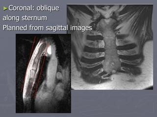
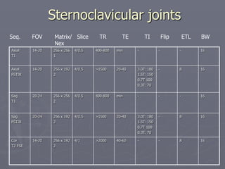
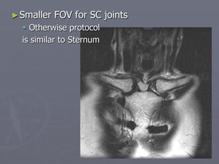
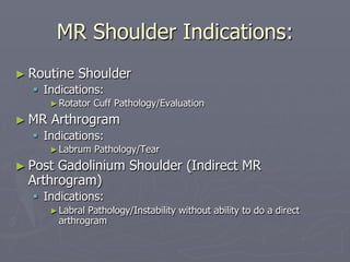
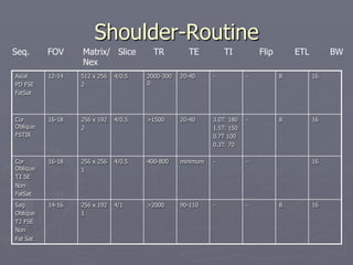
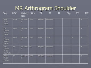
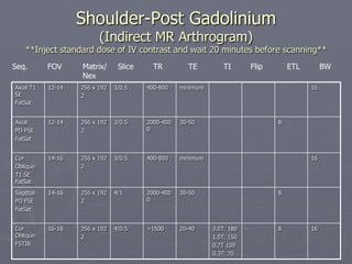
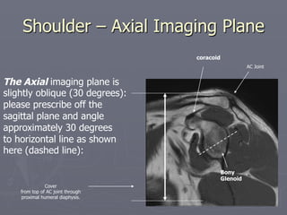
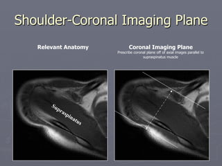
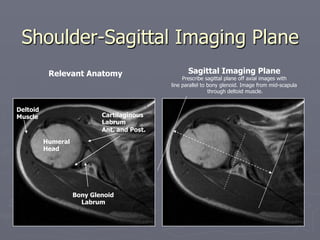
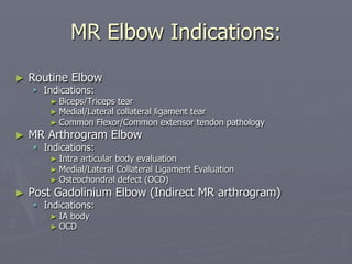
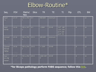
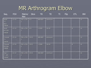
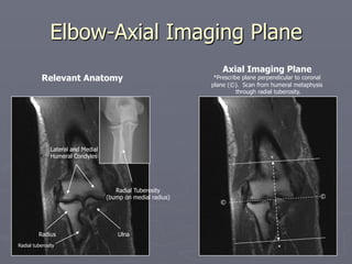
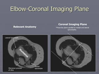
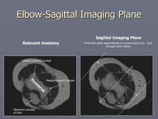
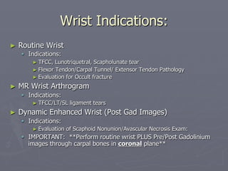
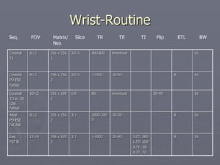
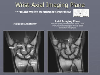
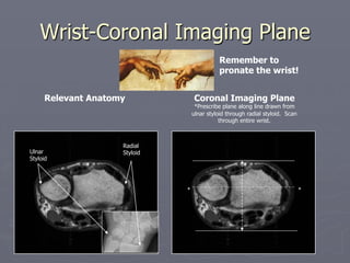
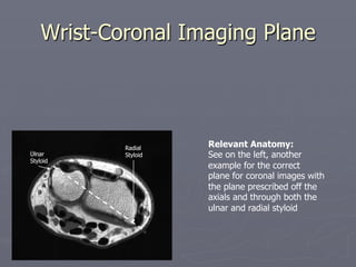
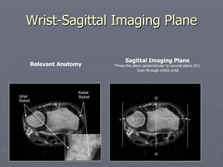
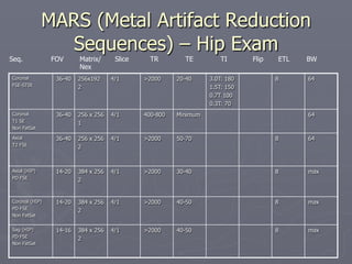
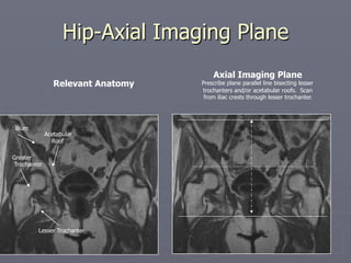
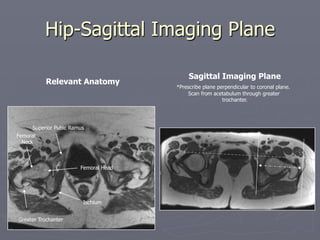
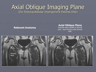
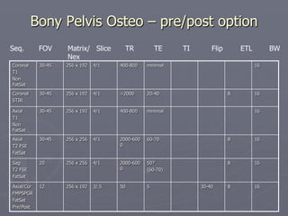
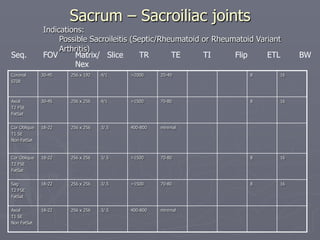
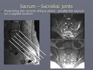
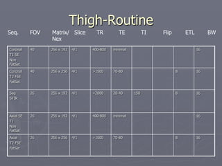
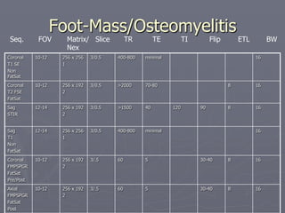
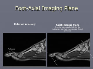
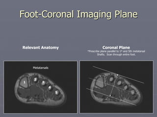
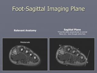
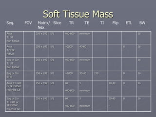
SlideShare a Scribd company logo
1 of 92
MSK MRI PROTOCOLS
Contents
► Upper Extremity Page
► Shoulder
► Elbow
► Wrist
► Finger
► Thumb
► Lower Extremity
► Hip
► Pelvis
► Thigh
► Knee
► Lower Extremity/Shin
► Ankle
► Foot
► Special Cases
► Soft Tissue Mass
► Metal Protocol
MSK CHEST
MR MSK Chest Indications:
►Pectoralis Major
§ Indications:
►Pec tear
►Sternum / SC joints
§ Indications:
►Tumor, infection, arthritis, trauma
►Chest wall
§ Indications:
►Trauma, tumor
Pectoralis Major
►Use large FOV
§ Medial-lateral: cover to midline chest
§ Superior-inferior: cover down to mid-humeral
shaft
FOV
Pectoralis Major
Axial
T1
30-36 256 x 256
1
4/0.5 400-800 min - - - 16
Axial
FSTIR
30-36 256 x 192
2
4/0.5 >1500 20-40 3.0T: 180
1.5T: 150
0.7T 100
0.3T: 70
- 8 16
Axial
T2 FSE
30-36 256 x 256
2
4/0.5 >2000 80-100 - - 8 16
Cor Obl
FSTIR
36-48 256 x 192
2
4/0.5 >1500 20-40 3.0T: 180
1.5T: 150
0.7T 100
0.3T: 70
- 8 16
Sag
Oblique
T2 FSE
Fat Sat
30-36 256 x 192
2
4/1 >2000 40-60 - - 8 16
Seq. FOV Matrix/ Slice TR TE TI Flip ETL BW
Nex
Sternum
Axial
T1
20-24 256 x 256
1
4/0.5 400-800 min - - - 16
Axial
FSTIR
24 256 x 192
2
4/0.5 >1500 20-40 3.0T: 180
1.5T: 150
0.7T 100
0.3T: 70
- 8 16
Sag
T1
20-30 256 x 256
2
4/0.5 400-800 min - - - 16
Sag
FSTIR
20-30 256 x 192
2
4/0.5 >1500 20-40 3.0T: 180
1.5T: 150
0.7T 100
0.3T: 70
- 8 16
Cor
oblique
T2 FSE
20-24 256 x 192
2
4/1 >2000 40-60 - - 8 16
Seq. FOV Matrix/ Slice TR TE TI Flip ETL BW
Nex
►Coronal: oblique
along sternum
Planned from sagittal images
Sternoclavicular joints
Axial
T1
14-20 256 x 256
1
4/0.5 400-800 min - - - 16
Axial
FSTIR
14-20 256 x 192
2
4/0.5 >1500 20-40 3.0T: 180
1.5T: 150
0.7T 100
0.3T: 70
- 8 16
Sag
T1
20-24 256 x 256
2
4/0.5 400-800 min - - - 16
Sag
FSTIR
20-24 256 x 192
2
4/0.5 >1500 20-40 3.0T: 180
1.5T: 150
0.7T 100
0.3T: 70
- 8 16
Cor
T2 FSE
14-20 256 x 192
2
4/1 >2000 40-60 - - 8 16
Seq. FOV Matrix/ Slice TR TE TI Flip ETL BW
Nex
►Smaller FOV for SC joints
§ Otherwise protocol
is similar to Sternum
MSK - Chest Wall
UPPER EXTREMITY
MR Shoulder Indications:
► Routine Shoulder
§ Indications:
►Rotator Cuff Pathology/Evaluation
► MR Arthrogram
§ Indications:
►Labrum Pathology/Tear
► Post Gadolinium Shoulder (Indirect MR
Arthrogram)
§ Indications:
►Labral Pathology/Instability without ability to do a direct
arthrogram
Shoulder-Routine
Axial
PD FSE
FatSat
12-14 512 x 256
2
4/0.5 2000-300
0
20-40 - - 8 16
Cor
Oblique
FSTIR
16-18 256 x 192
2
4/0.5 >1500 20-40 3.0T: 180
1.5T: 150
0.7T 100
0.3T: 70
- 8 16
Cor
Oblique
T1 SE
Non
FatSat
16-18 256 x 256
1
4/0.5 400-800 minimum - - 16
Sag
Oblique
T2 FSE
Non
Fat Sat
14-16 256 x 192
1
4/1 >2000 90-110 - - 8 16
Seq. FOV Matrix/ Slice TR TE TI Flip ETL BW
Nex
MR Arthrogram Shoulder
Axial
T1 SE
FatSat
12-14 256 x 192
2
3/0.5 400-800 minimum 16
Cor
Oblique
T1 SE
FatSat
14-16 256 x 192
2
3/0.5 400-800 minimum 16
Cor
Oblique
PD FSE
FatSat
14-16 256 x 192
2
3/0.5 >1500 30-50 8 16
Sag
Oblique
T1 SE
Non FatSat
14 256 x 192
1
4/1 400-800 minimum 16
ABER
T1 SE
Fat Sat
14 256 x 192
2
3/0.5 400-800 minimum 16
Seq. FOV Matrix/ Slice TR TE TI Flip ETL BW
Nex
Shoulder-Post Gadolinium
(Indirect MR Arthrogram)
**Inject standard dose of IV contrast and wait 20 minutes before scanning**
Axial T1
SE
FatSat
12-14 256 x 192
2
3/0.5 400-800 minimum 16
Axial
PD FSE
FatSat
12-14 256 x 192
2
3/0.5 2000-400
0
30-50 8
Cor
Oblique
T1 SE
FatSat
14-16 256 x 192
2
3/0.5 400-800 minimum 16
Sagittal
PD FSE
FatSat
14-16 256 x 192
2
4/1 2000-400
0
30-50 8
Cor
Oblique
FSTIR
16-18 256 x 192
2
4/0.5 >1500 20-40 3.0T: 180
1.5T: 150
0.7T 100
0.3T: 70
- 8 16
Seq. FOV Matrix/ Slice TR TE TI Flip ETL BW
Nex
Shoulder – Axial Imaging Plane
The Axial imaging plane is
slightly oblique (30 degrees):
please prescribe off the
sagittal plane and angle
approximately 30 degrees
to horizontal line as shown
here (dashed line):
Bony
Glenoid
coracoid
AC Joint
Cover
from top of AC joint through
proximal humeral diaphysis.
Shoulder-Coronal Imaging Plane
Coronal Imaging Plane
Prescribe coronal plane off of axial images parallel to
supraspinatus muscle
Relevant Anatomy
Shoulder-Sagittal Imaging Plane
Humeral
Head
Bony Glenoid
Labrum
Cartilaginous
Labrum
Ant. and Post.
Relevant Anatomy Sagittal Imaging Plane
Prescribe sagittal plane off axial images with
line parallel to bony glenoid. Image from mid-scapula
through deltoid muscle.
Deltoid
Muscle
MR Elbow Indications:
► Routine Elbow
§ Indications:
► Biceps/Triceps tear
► Medial/Lateral collateral ligament tear
► Common Flexor/Common extensor tendon pathology
► MR Arthrogram Elbow
§ Indications:
► Intra articular body evaluation
► Medial/Lateral Collateral Ligament Evaluation
► Osteochondral defect (OCD)
► Post Gadolinium Elbow (Indirect MR arthrogram)
§ Indications:
► IA body
► OCD
Elbow-Routine*
Axial
T1
12-14 256 x 256
1
4/1 400-800 minimum 16
Axial
FSTIR
14-16 256 x 192
2
4/1 >2000 20-40 3.0T: 180
1.5T: 150
0.7T 100
0.3T: 70
8 16
Coronal
T1
14-16 256 x 256
1
3/0.5 400-800 minimum 16
Coronal
PD FSE
FatSat
14-16 256 x 256
2
3/0.5 > 1500 20-40 8 16
Sag
PD FSE
FatSat
12-14 256 x 256
2
3/0.5 1500-300
0
20-40 8 16
Seq. FOV Matrix/ Slice TR TE TI Flip ETL BW
Nex
*for Biceps pathology perform FABS sequence; follow this link.
MR Arthrogram Elbow
Axial
T1
Non
FatSat
12-14 256 x 256
1
4/1 400-800 minimum 16
Axial
PD FSE
FatSat
12-14 256 x 256
2
4/1 >1500 30-50 8 16
Coronal
T1
FatSat
12-14 256 x 256
2
3/0.5 400-800 minimum 16
Coronal
PD FSE
FatSat
12-14 256 x 256
2
3/0.5 >1500 30-50 8 16
Sag
T1 SE
FatSat
12-14 256 x 256
2
3/0.5 400-800 minimum 16
Seq. FOV Matrix/ Slice TR TE TI Flip ETL BW
Nex
Elbow-Axial Imaging Plane
Relevant Anatomy
Axial Imaging Plane
*Prescribe plane perpendicular to coronal
plane (©). Scan from humeral metaphysis
through radial tuberosity.
©
©
*
*
Radial Tuberosity
(bump on medial radius)
Lateral and Medial
Humeral Condyles
Ulna
Radius
Radial tuberosity
Elbow-Coronal Imaging Plane
Relevant Anatomy
Coronal Imaging Plane
*Prescribe plane parallel to medial and lateral
epicondyles.
*
*
Lateral Epicondyle
Medial
Epicondyle
Olecranon process
of Ulna
Elbow-Sagittal Imaging Plane
Sagittal Imaging Plane
*Prescribe plane perpendicular to coronal plane (©). Scan
through entire elbow.
©
©
*
*
Lateral Humeral Condyle
Medial Humeral Condyle
Olecranon process
of Ulna
Relevant Anatomy
FABS Sequence
►For Biceps pathology
§ Acquire T1 and T2 FS
Wrist Indications:
► Routine Wrist
§ Indications:
► TFCC, Lunotriquetral, Scapholunate tear
► Flexor Tendon/Carpal Tunnel/ Extensor Tendon Pathology
► Evaluation for Occult fracture
► MR Wrist Arthrogram
§ Indications:
► TFCC/LT/SL ligament tears
► Dynamic Enhanced Wrist (Post Gad Images)
§ Indications:
► Evaluation of Scaphoid Nonunion/Avascular Necrosis Exam:
§ IMPORTANT: **Perform routine wrist PLUS Pre/Post Gadolinium
images through carpal bones in coronal plane**
Wrist-Routine
Coronal
T1
8-12 256 x 256
1
3/0.5 400-800 minimum 16
Coronal
PD FSE
FatSat
8-12 256 x 256
2
3/0.5 >1500 30-50 8 16
Coronal
2D or 3D
GRE
FatSat
10-12 256 x 192
2
1/0 60 minimum 20-40 16
Axial
PD FSE
Fat Sat
8-12 256 x 256
2
3/1 2000-300
0
30-50 8 16
Sag
FSTIR
12-14 256 x 192
2
3/1 >1500 20-40 3.0T: 180
1.5T: 150
0.7T 100
0.3T: 70
8 16
Seq. FOV Matrix/ Slice TR TE TI Flip ETL BW
Nex
MR Arthrogram Wrist (direct or indirect)
Coronal
T1 SE
FatSat
8-10 256 x 256
2
3/0.5 400-800 minimum 16
Coronal
PD FSE
FatSat
8-12 256 x 256
2
3/0.5 >1500 30-50 8 16
Coronal
2D or 3D
GRE
FatSat
10-12 256 x 192
2
1/0 60 minimum 45-60 16
Axial
PD FSE
FatSat
8-12 256 x 256
2
3/1 >1500 30-50 8 16
Axial
T1
Non-
FatSat
8-12 256 x 192
1
3/1 400-800 minimum 16
Sag
PD FSE
FatSat
10-12 3/1 >1500 30-50 8 16
Seq. FOV Matrix/ Slice TR TE TI Flip ETL BW
Nex
Wrist-Axial Imaging Plane
Distal
ulna
cap
Dist
radius
trapm
trapz ham
Relevant Anatomy
Axial Imaging Plane
Prescribe plane parallel to distal radius. Scan
from proximal metacarpals through distal
radial/ulnar metaphysis.
***IMAGE WRIST IN PRONATED POSITION!
SUPINATED PRONATED
Wrist-Coronal Imaging Plane
Relevant Anatomy Coronal Imaging Plane
*Prescribe plane along line drawn from
ulnar styloid through radial styloid. Scan
through entire wrist.
* *
Ulnar
Styloid
Radial
Styloid
Remember to
pronate the wrist!
Wrist-Coronal Imaging Plane
Ulnar
Styloid
Radial
Styloid
Relevant Anatomy:
See on the left, another
example for the correct
plane for coronal images with
the plane prescribed off the
axials and through both the
ulnar and radial styloid
Ulnar
Styloid
Radial
Styloid
Wrist-Sagittal Imaging Plane
Ulnar
Styloid
Radial
Styloid
Relevant Anatomy
Sagittal Imaging Plane
*Prescribe plane perpendicular to coronal plane (©).
Scan through entire wrist.
©
©
*
*
Ulnar
Styloid
Radial
Styloid
Hint: if the ulnar styloid is poking
out to the side, the wrist is
in pronated position
Thumb Indications:
►Routine Thumb
§ Indications:
►Gamekeeper’s thumb (Ulnar Collateral Ligament
tear)
►Flexor/Extensor Tendon Tear
►R/O Occult Fracture
Thumb
Coronal
PD FSE
10 256 x 256
2
3/0.3 >1500 30-50 4
Coronal
T2 FSE
Fat Sat
10 256 x 192
2
3/0.3 2000-600
0
50-70 8 16
Sag FSE
STIR
10-14 256 x 192
2
3/0.3 >1500 20-40 3.0T: 180
1.5T: 150
0.7T 100
0.3T: 70
8 16
Axial
T1 SE
10 256 x 192
1
3/0.3 400-800 minimal
Axial
T2 FSE
Fat Sat
10 256 x 192
2
3/0.3 2000-600
0
50-70 8 16
Seq. FOV Matrix/ Slice TR TE TI Flip ETL BW
Nex
Thumb-Axial Imaging Plane
Relevant Anatomy
Axial Imaging Plane
Prescribe plane perpendicular to midshaft of
proximal 1st phalanx. Scan from CMC joint
through thumb.
Thumb-Coronal Imaging Plane
Relevant Anatomy
Coronal Imaging Plane
*Prescribe plane along line bisecting
sesamoid bones or if sesamoids are not well seen along line
bisecting the 1st metatarsal head
(red lines through the yellow square shown below).
Scan through entire thumb.
Sesamoids
Thumb
*
Thumb-Sagittal Imaging Plane
Sesamoids
Thumb
Relevant Anatomy Sagittal Imaging Plane
*Prescribe plane perpendicular to coronal
imaging plane (©). Scan through entire thumb.
©
*
Finger Indications:
► Routine Finger
§ Indications:
►Pulley rupture/Flexor or Extensor Tendon Injury
► Post Gadolinium Finger
§ Indications:
►Mass
►**Perform routine finger plus Axial and either Coronal or
Sagittal (whichever plane mass best seen) pre/post gadolinium
FatSat fast GRE or T1 SE images. See “mass” protocol and
adjust FOV and other parameters as needed.
Finger-Routine
Sag
T1 SE
10 256 x 192
1
3/0.3 400-800 minimum 16
Sag
T2 FSE
FatSat
10 256 x 192
2
3/0.3 2000-600
0
50-70 8 16
Axial
T1 SE
10 256 x 192
2
3/0.3 400-800 minimum 16
Axial
PD FSE
FatSat
10 256 x256
2
3/0.3 2000-600
0
30-50 4 16
Coronal
STIR
10-14 256 x256
2
3/0.3 >1500 20-40 3.0T: 180
1.5T: 150
0.7T 100
0.3T: 70
8 16
Seq. FOV Matrix/ Slice TR TE TI Flip ETL BW
Nex
Finger-Axial Imaging Plane
Distal
Phalanx
Mid
Phalanx
Metacarpal
Proximal
Phalanx
Relevant
Anatomy
Axial Imaging Plane
Prescribe best fit line. Scan from
proximal metacarpal through entire
finger.
Finger-Coronal Imaging Plane
Relevant Anatomy Coronal Imaging Plane
*Prescribe plane parallel to anterior
metacarpal head. Scan through entire
finger. Include 2 adjacent fingers.
*
Thumb
Extensor Tendon
Finger-Sagittal Imaging Plane
Relevant Anatomy
Sagittal Imaging Plane
*Prescribe plane perpendicular to
coronal plane (©). Scan through entire
finger. Include 2 adjacent fingers.
*
©
Thumb
Extensor Tendon
LOWER EXTREMITY
Bony pelvis
► Indication: AVN, Mets, transient osteoporosis, bursitis, arthritis,
tendonitis, hip pain over age 50
► PA Torso Coil is 1st choice
Coronal
FSE-STIR
36-40 256x192
2-3
4/1 >2000 20-40 150 8 16
Axial
T2 FSE
FatSat
36-40 256 x 256
2
5/1.5 3000 30-40 8 16
Coronal
T1 SE
Non FatSat
36-40 256 x 256
1
4/1 400-800 Minimum 16
Sag
T2 FSE
FatSat
(Hip to Hip)
12-16 256 x 256
1-2
5/1 >2000 40-50 8 16
Coronal in/
out of phase
T1 GRE
Seq. FOV Matrix/ Slice TR TE TI Flip ETL BW
Nex
ER Hip
(Hip fracture screening)
Coronal
FSE-STIR
36-40 256x192
2
4/1 >2000 20-40 3.0T: 180
1.5T: 150
0.7T 100
0.3T: 70
8 16
Coronal
T1 SE
Non FatSat
36-40 256 x 256
1
4/1 400-800 Minimum 16
Axial
T2 FSE
FatSat
36-40 256 x 256
2
4/1 >2000 80-110 8 16
Seq. FOV Matrix/ Slice TR TE TI Flip ETL BW
Nex
Coronal (PELVIS)
T1 SE
Non FatSat
36-40 256 x 256
1
4/1 400-800 Minimum 16
Coronal (PELVIS)
FSE-STIR
36-40 256x192
2
4/1 >2000 20-40 3.0T: 180
1.5T: 150
0.7T 100
0.3T: 70
8 16
Axial (PELVIS)
T2 FSE
FatSat
36-40 256 x 256
2
4/1 >2000 40-50 8 16
Ax oblique (HIP)
T1 FatSat
14-20 384 x 256
2
4/0.5 400-800 Minimum 16
Coronal (HIP)
T1 FatSat
14-20 384 x 256
2
4/0.5 400-800 Minimum 16
Sag (HIP)
T1 FatSat
14-16 384 x 256
2
4/0.5 400-800 Minimum 16
Seq. FOV Matrix/ Slice TR TE TI Flip ETL BW
Nex
Direct arthrogram hip
► Indication: hip labrum tear, FAI or dysplasia, hip pain under age 50
► PA Torso coil is 1st choice
► Prescribe obliques along femoral neck from coronal localizer
Coronal (PELVIS)
T1 SE
Non FatSat
36-40 256 x 256
1
4/1 400-800 Minimum 16
Coronal (PELVIS)
FSE-STIR
36-40 256x192
2
4/1 >2000 20-40 3.0T: 180
1.5T: 150
0.7T 100
0.3T: 70
8 16
Axial (PELVIS)
T2 FSE
FatSat
36-40 256 x 256
2
4/1 >2000 40-50 8 16
Ax oblique (HIP)
PD FSE
FatSat
14-20 384 x 256
2
4/1 >2000 30-40 8 16
Coronal (HIP)
PD FSE
FatSat
14-20 384 x 256
2
4/1 >2000 40-50 8 16
Sag (HIP)
PD FSE
FatSat
14-16 384 x 256
2
4/1 >2000 40-50 8 16
Seq. FOV Matrix/ Slice TR TE TI Flip ETL BW
Nex
Noncontrast hip
► Indication: Unilateral hip pain
► PA Torso coil is 1st choice
► Prescribe ax obliques along femoral neck from coronal localizer
Metal Protocol – general
recommendations
►Use FSE instead of conventional SE
►Maximize BW (bandwidth)
►Lower TE for T2 and STIR
►Remove fat suppression
►Avoid GRE
►Use STIR instead of T2w fat sat
MARS (Metal Artifact Reduction
Sequences) – Hip Exam
Coronal
FSE-STIR
36-40 256x192
2
4/1 >2000 20-40 3.0T: 180
1.5T: 150
0.7T 100
0.3T: 70
8 64
Coronal
T1 SE
Non FatSat
36-40 256 x 256
1
4/1 400-800 Minimum 64
Axial
T2 FSE
36-40 256 x 256
2
4/1 >2000 50-70 8 64
Axial (HIP)
PD FSE
14-20 384 x 256
2
4/1 >2000 30-40 8 max
Coronal (HIP)
PD FSE
Non FatSat
14-20 384 x 256
2
4/1 >2000 40-50 8 max
Sag (HIP)
PD FSE
Non FatSat
14-16 384 x 256
2
4/1 >2000 40-50 8 max
Seq. FOV Matrix/ Slice TR TE TI Flip ETL BW
Nex
Hip-Axial Imaging Plane
Lesser Trochanter
Greater
Trochanter
Ilium
Acetabular
Roof
Relevant Anatomy
Axial Imaging Plane
Prescribe plane parallel line bisecting lesser
trochanters and/or acetabular roofs. Scan
from iliac crests through lesser trochanter.
Hip-Coronal Imaging Plane
Greater Trochanter
Femoral
Neck
Superior Pubic Ramus
Relevant Anatomy
Coronal Imaging Plane
*Prescribe plane parallel femoral heads.
Scan from ischium through pubic
symphyses.
Ischium
*
Femoral
Head
Hip-Sagittal Imaging Plane
Greater Trochanter
Femoral
Neck
Superior Pubic Ramus
Femoral Head
Ischium
Relevant Anatomy
Sagittal Imaging Plane
*Prescribe plane perpendicular to coronal plane.
Scan from acetabulum through greater
trochanter.
*
Axial Oblique Imaging Plane
(For Femoracetabular Impingement Patients Only)
Axial Oblique Plane
Prescribe plane parallel to femoral
neck. Scan through entire femoral
neck.
Relevant Anatomy
Femoral
Neck
Femoral
Head
Coronal
STIR
28-36
(Both hips)
256x192
2-3
4/1 >2000 20-40 150 8 16
Coronal
T1 SE
28
(Both hips)
256x256
1-2
4/1 400-800 minimum 16
Axial T2 FSE
Fat Sat
28
(Both hips)
256x256
2-3
5/1 >2000 50-60 8 16
Axial Obl PD FSE
Nonfatsat
20 256x192
1-2
4/.5 3000
(max)
25-30 4 16
Axial Obl T2 FSE
Fat Sat
20 256x192
2-3
4/.5 >2000 50-60 8 16
Sag T2 FSE
Fat Sat
20-22 256x192
2-3
4/.5 >2000 50-60 8 16
Sag PD FSE
Nonfatsat
(optional)
20-22 256x256
2-3
4/.5 >2000 20-30 8 16
Seq. FOV Matrix/NEX Slice TR TE TI ETL BW
TJUH Athletic Pubalgia MR Protocol
► Indication: Athletic Pubalgia, Sports Hernia, Sportsman’s Hernia, Adductor tear/
strain, Rectus Abdominis Injury
► PA Torso coil is 1st choice
► Prescribe obliques along anterior iliac crest from sagittal localizer
Axial Oblique Imaging Plane
(Adductor unfolding plane)
Relevant Anatomy
Axial Oblique Imaging Plane
*Prescribe plane to line paralleling anterior
Iliac crest*. Be sure to scan across pubic
symphysis at midline
*
*
Hip joint
Axial Oblique Imaging Plane
(Adductor unfolding plane)
Bony Pelvis
(Special Cases)
*Follow Hip Planes*
► Post Gadolinium Pelvis
§ Indications:
►Osteomylitis
§ IMPORTANT:
►Same as Routine Hip Protocol but perform axial and coronal
images on both sides.
►In addition, perform FMPSPGR fat saturated images pre/post in
both axial and coronal planes.
► In/Out of Phase Pelvis
§ Indications:
►Possible Bony Metastases
§ IMPORTANT:
►Perform In/Out of Phase images in Coronal Plane
Bony Pelvis Osteo – pre/post option
Coronal
T1
Non
FatSat
30-45 256 x 192 4/1 400-800 minimal 16
Coronal
STIR
30-45 256 x 192 4/1 >2000 20-40 8 16
Axial
T1
Non
FatSat
30-45 256 x 192 4/1 400-800 minimal 16
Axial
T2 FSE
FatSat
30-45 256 x 256 4/1 2000-600
0
60-70 8 16
Sag
T2 FSE
FatSat
20 256 x 256 4/1 2000-600
0
50?
(60-70)
8 16
Axial/Cor
FMPSPGR
FatSat
Pre/Post
12 256 x 192 3/.5 50 5 30-40 8 16
Seq. FOV Matrix/ Slice TR TE TI Flip ETL BW
Nex
Sacrum – Sacroiliac joints
Coronal
STIR
30-45 256 x 192 4/1 >2000 20-40 8 16
Axial
T2 FSE
FatSat
30-45 256 x 256 4/1 >1500 70-80 8 16
Cor Oblique
T1 SE
Non FatSat
18-22 256 x 256 3/.5 400-800 minimal
Cor Oblique
T2 FSE
FatSat
18-22 256 x 256 3/.5 >1500 70-80 8 16
Sag
T2 FSE
FatSat
18-22 256 x 256 3/.5 >1500 70-80 8 16
Axial
T1 SE
Non FatSat
18-22 256 x 256 3/.5 400-800 minimal
Seq. FOV Matrix/ Slice TR TE TI Flip ETL BW
Nex
Indications:
Possible Sacroileitis (Septic/Rheumatoid or Rheumatoid Variant
Arthritis)
Sacrum – Sacroiliac joints
► Prescribing the coronal oblique plane: parallel the sacrum
on a sagittal localizer
Routine Thigh
(Follow Hip Imaging Planes)
►Routine Thigh
§ Indications:
►Polymyositis/Diabetic Myonecrosis
Thigh-Routine
Coronal
T1 SE
Non
FatSat
40 256 x 192 4/1 400-800 minimal 16
Coronal
T2 FSE
FatSat
40 256 x 256 4/1 >1500 70-80 8 16
Sag
STIR
26 256 x 192 4/1 >2000 20-40 150 8 16
Axial SE
T1
Non
FatSat
26 256 x 192 4/1 400-800 minimal 16
Axial
T2 FSE
FatSat
26 256 x 256 4/1 >1500 70-80 8 16
Seq. FOV Matrix/ Slice TR TE TI Flip ETL BW
Nex
Knee Indications
► Routine Knee
§ Indications:
►Meniscal Tear/Medial or Lateral Ligament Tear/ACL/PCL
► Direct Arthrogram
§ Indications:
►Meniscal Re-tear
►Intra articular Body
► Post Gadolinium Knee
§ Indications
►Meniscal Re-tear
§ IMPORTANT: Image 20 minutes post gadolinium
Knee-Routine
Sag
PD FSE
NonFatSat
14-16 512 x 256
2
4/0.5 3000 15-20 8 16
Sag
T2 FSE
FatSat
14-16 256 x 256
2
4/0.5 2000 70-80 8 16
Cor
T1 SE
Non FatSat
16-18 256 x 192
1
3/0.5 400-800 Minimal 16
Coronal
T2 FSE
Fat Sat
16-18 256 x 256
2
3/0.5 >2000 70-80 8 16
Axial
T2 FSE
FatSat
14-16 256 x 256
2
3/0.5 >2000 70-80 8 16
Seq. FOV Matrix/ Slice TR TE TI Flip ETL BW
Nex
MR Arthrogram Knee (dir or ind)
Sag
T1 Se
FatSat
14-16 256 x 192 4/1 400-800 Minimal 16
Sag
PD FSE
NonFatSat
14-16 512 x 256
2
4/0.5 3000 15-20 8 16
Coronal
T2 FSE
FatSat
16-18 256 x 256
2
4/1 >1500 70-80 8 16
Coronal
T1 SE
FatSat
16-18 256 x 192
1
4/1 400-800 Minimal 16
Axial
T2 FSE
FatSat
14-16 256 x 256 4/1 >1500 70-80 8 16
Axial
T1 SE
FatSat
14-16 256 x 192 4/1 400-800 Minimal 16
Seq. FOV Matrix/ Slice TR TE TI Flip ETL BW
Nex
Knee-Axial Imaging Plane
P
A
T
Tibia
Femur
Patellar
Tendon
Insertion
Relevant Anatomy Axial Imaging Plane
Image from distal quad tendon
through patellar tendon insertion
Distal Quadriceps tendon
Knee-Coronal Imaging
Relevant Anatomy
Med
Fem
Condyle
Lat
Fem
Condyle
Patella
Coronal Imaging Plane
Prescribe plane with line parallel to
femoral condyles. Image entire knee.
Knee-Sagittal Imaging Plane
Med
Fem
Condyle
Lat
Fem
Condyle
Patella
Relevant Anatomy
Sagittal Imaging Plane
*Prescribe plane perpendicular to coronal plane (©).
Scan from the medial to the lateral femoral condyle.
©
©
*
*
Lower Extremity/Shin
►Indication:
§ Shin Splints
►IMPORTANT:
§ Acquire coronal and axial (STIR) sequences
covering both shins, but sagittal and axial (t2
FatSat only of side in question
§ Place a marker on pain / tenderness
Lower Extremity/Shin Area
Coronal
T1 SE
Non
FatSat
35-40 256 x 256 4/1 400-800 minimal 16
Coronal
STIR
35-40 256 x 192 4/1 >2000 20-40 150 8 16
Axial
STIR
35-40 256 x 192 4/1 >2000 20-40 150 8 16
Axial
T2 FSE
FatSat
(through
marker
region)
14-16 256 x 256 4/1 >1500 70-80 8 16
Sag
T2 FSE
FatSat
256 x 256 4/1 >1500 70-80 8 16
Seq. FOV Matrix/ Slice TR TE TI Flip ETL BW
Nex
Ankle Indications
►Routine Ankle
§ Ligament Sprain/Tendon pathology/Tarsal
Tunnel/Sinus Tarsi/Occult fracture, PTT, Plantar
fasciitis
►Ankle Arthrogram
§ Indications:
►Intra-articular Body
►Post Gadolinium Ankle
Ankle-Routine
Sag
T1 SE
Non
FatSat
16-18 256 x 256
1
3/1 400-800 Minimal 16
Sag
STIR
16-18 256 x 192
3
3/1 >1500 40 120 90 8 16
Axial
PD FSE
Non
FatSat
14-16 384 x 256
2
4/1 3000 40 8 16
Axial
T2 FSE
FatSat
14-16 256 x 256
2
4/1 >2000 70-80 8 16
Coronal
T2 FSE
FatSat
14 256 x 256
3
3/1 >2000 40-55 8 16
Seq. FOV Matrix/ Slice TR TE TI Flip ETL BW
Nex
MR Arthrogram Ankle (dir or ind)
Sag
T1 SE
FatSat
16 256 x 192 4/1 400-800 minimal 16
Sag
STIR
18 256 x 192 4/1 >2000 20-40 150 8 16
Axial
T1 SE
FatSat
14 256 x 256 4/1 800 min 16
Axial
PD FSE
Non
FatSat
14-16 513 x 256
2
4/1 3000 40 8 16
Coronal
T1 SE
FatSat
14 256 x 192 4/1 400-800 minimal 16
Coronal
T2 FSE
FatSat
14 256 x 256 4/1 >1500 70-80 8 16
Seq. FOV Matrix/ Slice TR TE TI Flip ETL BW
Nex
Ankle-Post Contrast
Axial
FMPSPGR
FatSat
Pre/Post
14 256 x XX 200 ? 4 ? 16
Sag
T1 SE
Non
FatSat
16 256 x 192 4/1 400-800 minimal 16
Axial
T1 SE
FatSat
12 256 x 256 4/1 ?800 Minimal 16
Axial
PD FSE
FatSat
14 256 x 256 4/1 >2000 40-50 4 16
Cor
T1 SE
FatSat
14 256 x 256 4/1 400-800 minimal 16
Seq. FOV Matrix/ Slice TR TE TI Flip ETL BW
Nex
Ankle-Axial Imaging Plane
Tibia
Talus
Calcaneus
Relevant Anatomy
Axial Imaging Plane
Prescribe plane parallel to axis of calcaneus.
Scan ankle from distal tibia through subcutaneous
soft tissues (include plantar fascia).
Black band is plantar fascia
Ankle-Coronal Imaging Plane
Coronal Imaging Plane
Prescribe plane perpendicular
to axial imaging plane. Scan ankle
from calcaneus through metatarsal bases.
Calcaneus
Talus
Cuboid
Relevant Anatomy
Ankle-Sagittal Imaging Plane
Talus
Sagittal Imaging Plane
Prescribe plane with line parallel
to talus. Cover ankle from medial through lateral
malleolus.
Relevant Anatomy
Midfoot
Forefoot
Foot-Indications
► Routine Foot
§ Indications
►Plantar Plate Injury, R/O fracture, Lisfranc injury, tarsal/
metatarsal fracture
► Post Gadolinium Foot
§ Indications:
►Morton’s Neuroma
►Osteomyelitis
§ IMPORTANT: Perform routine foot plus coronal
FMPSPGR fat saturated pre and post gad images and
axial POST gad FMPSPGR fat saturated images.
Foot-Routine
Coronal
(short axis)
T1
Non FatSat
10 256 x 256
1
3/0.5 400-800 minimal 16
Coronal
(short axis)
T2 FSE
FatSat
10 256 x 256
2
3/0.5 >2000 70-80 8 16
Sag
STIR
12-14 256 x 192
3
3/0.5 >1500 40 120 90 8 16
Sag
T1
Non
FatSat
12-14 256 x 256
1
3/0.5 400-800 minimal 16
Axial
(long axis)
PD FSE
Non FatSat
12-14 256 x 256
2
3/0.5 >2000 30 8 16
Axial
(long axis)
T2 FSE
FatSat
12-14 256 x 256
2
3/0.5 >2000 90 8 16
Seq. FOV Matrix/ Slice TR TE TI Flip ETL BW
Nex
Foot-Mass/Osteomyelitis
Coronal
T1 SE
Non
FatSat
10-12 256 x 256
1
3/0.5 400-800 minimal 16
Coronal
T2 FSE
FatSat
10-12 256 x 192
2
3/0.5 >2000 70-80 8 16
Sag
STIR
12-14 256 x 192
2
3/0.5 >1500 40 120 90 8 16
Sag
T1
Non
FatSat
12-14 256 x 256
1
3/0.5 400-800 minimal 16
Coronal
FMPSPGR
FatSat
Pre/Post
10-12 256 x 192
2
3/.5 60 5 30-40 8 16
Axial
FMPSPGR
FatSat
Post
10-12 256 x 192
2
3/.5 60 5 30-40 8 16
Seq. FOV Matrix/ Slice TR TE TI Flip ETL BW
Nex
Foot-Axial Imaging Plane
Relevant Anatomy Axial Imaging Plane
Prescribe plane parallel to 2rd or 3rd
metatarsal. Scan foot from navicular through
phalanges.
N
A
V
Phalanges
Foot-Coronal Imaging Plane
Relevant Anatomy
Metatarsals
1
2
3
4
5
Coronal Plane
*Prescribe plane parallel to 1st and 5th metatarsal
Shafts. Scan through entire foot.
*
Foot-Sagittal Imaging Plane
*
*
Metatarsals
1
2
3
4
5
Sagittal Plane
*Prescribe plane perpendicular to coronal
Plane (©). Scan through entire foot.
Relevant Anatomy
©
©
*
Soft Tissue Mass Protocol
General Recommendations
►Place Vitamin E capsule LIGHTLY on skin
(do not depress skin with capsule)
§ If post-operative: place markers at each end of
surgical scar
►FOV determined by mass size / location
►Try to include adjacent joint for reference
►Axial always; Sag or Cor depending on
location of mass (speak with radiologist)
Soft Tissue Mass
Axial
T1 SE
Non FatSat
256 x 192 5/1 400-800 minimum 16
Axial
T2 FSE
FatSat
256 x 192 5/1 >2000 40-60 8 16
Sag or Cor
T1 SE
Non FatSat
256 x 192 5/1 400-800 minimum 16
Sag or Cor
STIR
256 x 192 5/1 >2000 30-40 150 8 16
Axial T1 GRE
or SE FatSat
Pre/Post Gd
256 x 192 5/1 60
400-800
5
minimum
30-40
-
8 16
Sag or Cor
T1 GRE or
SE FatSat
Pre/Post Gd
256 x 192 5/1 60
400-800
5
minimum
30-40
-
8 16
Seq. FOV Matrix/ Slice TR TE TI Flip ETL BW
Nex
MR Neurography Pelvis
Coronal
(PELVIS) T1 SE
Non FatSat
36-40 256 x 256
1
4/1 400-800 Minimum 16
Coronal
(PELVIS)
FSE-STIR
36-40 256x192
2
4/1 >2000 20-40 3.0T: 180
1.5T: 150
8 16
Axial (PELVIS)
T2 FSE
FatSat
24 (hip
to hip)
256 x 256
2
3.5/1 >2000 70-80 >8 16
Coronal T2 vista
(or equivalent)
30-34 232x345
1
2/1 2800 288 90 150
Axial T1 3D FFE 24 276 x276
1
3/1.5 28 2.3 30 1
Axial M FFE 24 240x160
1
3/0 3570 4 45 4
Sagittal PD
SPAIR
24-28 282x282
1
3.5/1 Max 45 90 >8
Seq. FOV Matrix/ Slice TR TE TI Flip ETL BW
Nex
Marrow Survey
ER / Inpatient Protocols
►Hip / pelvis fracture
►Joint: survey exam
►Non-contrast “R/O osteomyelitis”
►Chest wall / Abdominal wall
►Spine survey

More Related Content

Similar to MRI protocol complete may 2016 musculoskeletal

Presentation1.pptx, ultrasound examination of the knee joint.
Presentation1.pptx, ultrasound examination of the knee joint.Presentation1.pptx, ultrasound examination of the knee joint.
Presentation1.pptx, ultrasound examination of the knee joint.Abdellah Nazeer
 
Presentation1.pptx mri of elbow joint
Presentation1.pptx mri of elbow jointPresentation1.pptx mri of elbow joint
Presentation1.pptx mri of elbow jointAbdellah Nazeer
 
Presentation1, artifact and pitfalls of the knee, hip and ankle joints.
Presentation1, artifact and pitfalls of the knee, hip and ankle joints.Presentation1, artifact and pitfalls of the knee, hip and ankle joints.
Presentation1, artifact and pitfalls of the knee, hip and ankle joints.Abdellah Nazeer
 
Introduction to musculoskeletal radiology
Introduction to musculoskeletal radiologyIntroduction to musculoskeletal radiology
Introduction to musculoskeletal radiologySubhanjan Das
 
Ac dislocation dangtoandhy
Ac dislocation dangtoandhyAc dislocation dangtoandhy
Ac dislocation dangtoandhyDangToan8
 
26. acetabular fractures anatomy, evaluation and classification - muhammad...
26. acetabular fractures   anatomy, evaluation and classification  - muhammad...26. acetabular fractures   anatomy, evaluation and classification  - muhammad...
26. acetabular fractures anatomy, evaluation and classification - muhammad...Muhammad Abdelghani
 
Imaging of shoulder - Dr. Vishal Sankpal
Imaging of shoulder - Dr. Vishal SankpalImaging of shoulder - Dr. Vishal Sankpal
Imaging of shoulder - Dr. Vishal SankpalVishal Sankpal
 
CRANIOVERTEBRAL JUNCTION ANATOMY, CRANIOMETRY, ANAMOLIES AND RADIOLOGY dr sum...
CRANIOVERTEBRAL JUNCTION ANATOMY, CRANIOMETRY, ANAMOLIES AND RADIOLOGY dr sum...CRANIOVERTEBRAL JUNCTION ANATOMY, CRANIOMETRY, ANAMOLIES AND RADIOLOGY dr sum...
CRANIOVERTEBRAL JUNCTION ANATOMY, CRANIOMETRY, ANAMOLIES AND RADIOLOGY dr sum...SUMIT KUMAR
 
Applied surgical anatomy of the craniovertebral spine
Applied surgical anatomy of the craniovertebral spineApplied surgical anatomy of the craniovertebral spine
Applied surgical anatomy of the craniovertebral spineKshitij Chaudhary
 
Presentation1.pptx, ultrasound examination of the wrist joint.
Presentation1.pptx, ultrasound examination of the wrist joint.Presentation1.pptx, ultrasound examination of the wrist joint.
Presentation1.pptx, ultrasound examination of the wrist joint.Abdellah Nazeer
 
MRI WRIST SCAN PLANE AND LOCATION
MRI WRIST SCAN PLANE AND LOCATIONMRI WRIST SCAN PLANE AND LOCATION
MRI WRIST SCAN PLANE AND LOCATIONkina shah
 
The elbow joint in concern of diagnostic imaging .pptx 1
The elbow joint in concern of diagnostic imaging .pptx 1The elbow joint in concern of diagnostic imaging .pptx 1
The elbow joint in concern of diagnostic imaging .pptx 1DR Laith
 
Knee Problems and Knee Injuries Overview
Knee Problems and Knee Injuries OverviewKnee Problems and Knee Injuries Overview
Knee Problems and Knee Injuries OverviewKunal Shah
 
MRI of Knee joint-- hossam massoud
MRI of Knee joint-- hossam massoudMRI of Knee joint-- hossam massoud
MRI of Knee joint-- hossam massoudHossam Massoud
 
imaging of the craniovertebral junction
imaging of the craniovertebral junction imaging of the craniovertebral junction
imaging of the craniovertebral junction taraprasad tripathy
 

Similar to MRI protocol complete may 2016 musculoskeletal (20)

Presentation1.pptx, ultrasound examination of the knee joint.
Presentation1.pptx, ultrasound examination of the knee joint.Presentation1.pptx, ultrasound examination of the knee joint.
Presentation1.pptx, ultrasound examination of the knee joint.
 
Cervical spine trauma
Cervical spine traumaCervical spine trauma
Cervical spine trauma
 
Presentation1.pptx mri of elbow joint
Presentation1.pptx mri of elbow jointPresentation1.pptx mri of elbow joint
Presentation1.pptx mri of elbow joint
 
Presentation1, artifact and pitfalls of the knee, hip and ankle joints.
Presentation1, artifact and pitfalls of the knee, hip and ankle joints.Presentation1, artifact and pitfalls of the knee, hip and ankle joints.
Presentation1, artifact and pitfalls of the knee, hip and ankle joints.
 
Mri knee
Mri kneeMri knee
Mri knee
 
Introduction to musculoskeletal radiology
Introduction to musculoskeletal radiologyIntroduction to musculoskeletal radiology
Introduction to musculoskeletal radiology
 
Ac dislocation dangtoandhy
Ac dislocation dangtoandhyAc dislocation dangtoandhy
Ac dislocation dangtoandhy
 
26. acetabular fractures anatomy, evaluation and classification - muhammad...
26. acetabular fractures   anatomy, evaluation and classification  - muhammad...26. acetabular fractures   anatomy, evaluation and classification  - muhammad...
26. acetabular fractures anatomy, evaluation and classification - muhammad...
 
Ct&Mri
Ct&MriCt&Mri
Ct&Mri
 
Imaging of shoulder - Dr. Vishal Sankpal
Imaging of shoulder - Dr. Vishal SankpalImaging of shoulder - Dr. Vishal Sankpal
Imaging of shoulder - Dr. Vishal Sankpal
 
CRANIOVERTEBRAL JUNCTION ANATOMY, CRANIOMETRY, ANAMOLIES AND RADIOLOGY dr sum...
CRANIOVERTEBRAL JUNCTION ANATOMY, CRANIOMETRY, ANAMOLIES AND RADIOLOGY dr sum...CRANIOVERTEBRAL JUNCTION ANATOMY, CRANIOMETRY, ANAMOLIES AND RADIOLOGY dr sum...
CRANIOVERTEBRAL JUNCTION ANATOMY, CRANIOMETRY, ANAMOLIES AND RADIOLOGY dr sum...
 
Applied surgical anatomy of the craniovertebral spine
Applied surgical anatomy of the craniovertebral spineApplied surgical anatomy of the craniovertebral spine
Applied surgical anatomy of the craniovertebral spine
 
Presentation1.pptx, ultrasound examination of the wrist joint.
Presentation1.pptx, ultrasound examination of the wrist joint.Presentation1.pptx, ultrasound examination of the wrist joint.
Presentation1.pptx, ultrasound examination of the wrist joint.
 
Msk signs edited
Msk signs   editedMsk signs   edited
Msk signs edited
 
MRI WRIST SCAN PLANE AND LOCATION
MRI WRIST SCAN PLANE AND LOCATIONMRI WRIST SCAN PLANE AND LOCATION
MRI WRIST SCAN PLANE AND LOCATION
 
The elbow joint in concern of diagnostic imaging .pptx 1
The elbow joint in concern of diagnostic imaging .pptx 1The elbow joint in concern of diagnostic imaging .pptx 1
The elbow joint in concern of diagnostic imaging .pptx 1
 
Knee Problems and Knee Injuries Overview
Knee Problems and Knee Injuries OverviewKnee Problems and Knee Injuries Overview
Knee Problems and Knee Injuries Overview
 
MRI of Knee joint-- hossam massoud
MRI of Knee joint-- hossam massoudMRI of Knee joint-- hossam massoud
MRI of Knee joint-- hossam massoud
 
Nof fracture
Nof fractureNof fracture
Nof fracture
 
imaging of the craniovertebral junction
imaging of the craniovertebral junction imaging of the craniovertebral junction
imaging of the craniovertebral junction
 

Recently uploaded

Organic Name Reactions for the students and aspirants of Chemistry12th.pptx
Organic Name Reactions  for the students and aspirants of Chemistry12th.pptxOrganic Name Reactions  for the students and aspirants of Chemistry12th.pptx
Organic Name Reactions for the students and aspirants of Chemistry12th.pptxVS Mahajan Coaching Centre
 
“Oh GOSH! Reflecting on Hackteria's Collaborative Practices in a Global Do-It...
“Oh GOSH! Reflecting on Hackteria's Collaborative Practices in a Global Do-It...“Oh GOSH! Reflecting on Hackteria's Collaborative Practices in a Global Do-It...
“Oh GOSH! Reflecting on Hackteria's Collaborative Practices in a Global Do-It...Marc Dusseiller Dusjagr
 
Science 7 - LAND and SEA BREEZE and its Characteristics
Science 7 - LAND and SEA BREEZE and its CharacteristicsScience 7 - LAND and SEA BREEZE and its Characteristics
Science 7 - LAND and SEA BREEZE and its CharacteristicsKarinaGenton
 
Separation of Lanthanides/ Lanthanides and Actinides
Separation of Lanthanides/ Lanthanides and ActinidesSeparation of Lanthanides/ Lanthanides and Actinides
Separation of Lanthanides/ Lanthanides and ActinidesFatimaKhan178732
 
Crayon Activity Handout For the Crayon A
Crayon Activity Handout For the Crayon ACrayon Activity Handout For the Crayon A
Crayon Activity Handout For the Crayon AUnboundStockton
 
Industrial Policy - 1948, 1956, 1973, 1977, 1980, 1991
Industrial Policy - 1948, 1956, 1973, 1977, 1980, 1991Industrial Policy - 1948, 1956, 1973, 1977, 1980, 1991
Industrial Policy - 1948, 1956, 1973, 1977, 1980, 1991RKavithamani
 
BASLIQ CURRENT LOOKBOOK LOOKBOOK(1) (1).pdf
BASLIQ CURRENT LOOKBOOK  LOOKBOOK(1) (1).pdfBASLIQ CURRENT LOOKBOOK  LOOKBOOK(1) (1).pdf
BASLIQ CURRENT LOOKBOOK LOOKBOOK(1) (1).pdfSoniaTolstoy
 
Contemporary philippine arts from the regions_PPT_Module_12 [Autosaved] (1).pptx
Contemporary philippine arts from the regions_PPT_Module_12 [Autosaved] (1).pptxContemporary philippine arts from the regions_PPT_Module_12 [Autosaved] (1).pptx
Contemporary philippine arts from the regions_PPT_Module_12 [Autosaved] (1).pptxRoyAbrique
 
Sanyam Choudhary Chemistry practical.pdf
Sanyam Choudhary Chemistry practical.pdfSanyam Choudhary Chemistry practical.pdf
Sanyam Choudhary Chemistry practical.pdfsanyamsingh5019
 
Employee wellbeing at the workplace.pptx
Employee wellbeing at the workplace.pptxEmployee wellbeing at the workplace.pptx
Employee wellbeing at the workplace.pptxNirmalaLoungPoorunde1
 
SOCIAL AND HISTORICAL CONTEXT - LFTVD.pptx
SOCIAL AND HISTORICAL CONTEXT - LFTVD.pptxSOCIAL AND HISTORICAL CONTEXT - LFTVD.pptx
SOCIAL AND HISTORICAL CONTEXT - LFTVD.pptxiammrhaywood
 
Alper Gobel In Media Res Media Component
Alper Gobel In Media Res Media ComponentAlper Gobel In Media Res Media Component
Alper Gobel In Media Res Media ComponentInMediaRes1
 
How to Make a Pirate ship Primary Education.pptx
How to Make a Pirate ship Primary Education.pptxHow to Make a Pirate ship Primary Education.pptx
How to Make a Pirate ship Primary Education.pptxmanuelaromero2013
 
A Critique of the Proposed National Education Policy Reform
A Critique of the Proposed National Education Policy ReformA Critique of the Proposed National Education Policy Reform
A Critique of the Proposed National Education Policy ReformChameera Dedduwage
 
Measures of Central Tendency: Mean, Median and Mode
Measures of Central Tendency: Mean, Median and ModeMeasures of Central Tendency: Mean, Median and Mode
Measures of Central Tendency: Mean, Median and ModeThiyagu K
 
microwave assisted reaction. General introduction
microwave assisted reaction. General introductionmicrowave assisted reaction. General introduction
microwave assisted reaction. General introductionMaksud Ahmed
 
CARE OF CHILD IN INCUBATOR..........pptx
CARE OF CHILD IN INCUBATOR..........pptxCARE OF CHILD IN INCUBATOR..........pptx
CARE OF CHILD IN INCUBATOR..........pptxGaneshChakor2
 
Kisan Call Centre - To harness potential of ICT in Agriculture by answer farm...
Kisan Call Centre - To harness potential of ICT in Agriculture by answer farm...Kisan Call Centre - To harness potential of ICT in Agriculture by answer farm...
Kisan Call Centre - To harness potential of ICT in Agriculture by answer farm...Krashi Coaching
 
Solving Puzzles Benefits Everyone (English).pptx
Solving Puzzles Benefits Everyone (English).pptxSolving Puzzles Benefits Everyone (English).pptx
Solving Puzzles Benefits Everyone (English).pptxOH TEIK BIN
 

Recently uploaded (20)

Organic Name Reactions for the students and aspirants of Chemistry12th.pptx
Organic Name Reactions  for the students and aspirants of Chemistry12th.pptxOrganic Name Reactions  for the students and aspirants of Chemistry12th.pptx
Organic Name Reactions for the students and aspirants of Chemistry12th.pptx
 
“Oh GOSH! Reflecting on Hackteria's Collaborative Practices in a Global Do-It...
“Oh GOSH! Reflecting on Hackteria's Collaborative Practices in a Global Do-It...“Oh GOSH! Reflecting on Hackteria's Collaborative Practices in a Global Do-It...
“Oh GOSH! Reflecting on Hackteria's Collaborative Practices in a Global Do-It...
 
Science 7 - LAND and SEA BREEZE and its Characteristics
Science 7 - LAND and SEA BREEZE and its CharacteristicsScience 7 - LAND and SEA BREEZE and its Characteristics
Science 7 - LAND and SEA BREEZE and its Characteristics
 
Staff of Color (SOC) Retention Efforts DDSD
Staff of Color (SOC) Retention Efforts DDSDStaff of Color (SOC) Retention Efforts DDSD
Staff of Color (SOC) Retention Efforts DDSD
 
Separation of Lanthanides/ Lanthanides and Actinides
Separation of Lanthanides/ Lanthanides and ActinidesSeparation of Lanthanides/ Lanthanides and Actinides
Separation of Lanthanides/ Lanthanides and Actinides
 
Crayon Activity Handout For the Crayon A
Crayon Activity Handout For the Crayon ACrayon Activity Handout For the Crayon A
Crayon Activity Handout For the Crayon A
 
Industrial Policy - 1948, 1956, 1973, 1977, 1980, 1991
Industrial Policy - 1948, 1956, 1973, 1977, 1980, 1991Industrial Policy - 1948, 1956, 1973, 1977, 1980, 1991
Industrial Policy - 1948, 1956, 1973, 1977, 1980, 1991
 
BASLIQ CURRENT LOOKBOOK LOOKBOOK(1) (1).pdf
BASLIQ CURRENT LOOKBOOK  LOOKBOOK(1) (1).pdfBASLIQ CURRENT LOOKBOOK  LOOKBOOK(1) (1).pdf
BASLIQ CURRENT LOOKBOOK LOOKBOOK(1) (1).pdf
 
Contemporary philippine arts from the regions_PPT_Module_12 [Autosaved] (1).pptx
Contemporary philippine arts from the regions_PPT_Module_12 [Autosaved] (1).pptxContemporary philippine arts from the regions_PPT_Module_12 [Autosaved] (1).pptx
Contemporary philippine arts from the regions_PPT_Module_12 [Autosaved] (1).pptx
 
Sanyam Choudhary Chemistry practical.pdf
Sanyam Choudhary Chemistry practical.pdfSanyam Choudhary Chemistry practical.pdf
Sanyam Choudhary Chemistry practical.pdf
 
Employee wellbeing at the workplace.pptx
Employee wellbeing at the workplace.pptxEmployee wellbeing at the workplace.pptx
Employee wellbeing at the workplace.pptx
 
SOCIAL AND HISTORICAL CONTEXT - LFTVD.pptx
SOCIAL AND HISTORICAL CONTEXT - LFTVD.pptxSOCIAL AND HISTORICAL CONTEXT - LFTVD.pptx
SOCIAL AND HISTORICAL CONTEXT - LFTVD.pptx
 
Alper Gobel In Media Res Media Component
Alper Gobel In Media Res Media ComponentAlper Gobel In Media Res Media Component
Alper Gobel In Media Res Media Component
 
How to Make a Pirate ship Primary Education.pptx
How to Make a Pirate ship Primary Education.pptxHow to Make a Pirate ship Primary Education.pptx
How to Make a Pirate ship Primary Education.pptx
 
A Critique of the Proposed National Education Policy Reform
A Critique of the Proposed National Education Policy ReformA Critique of the Proposed National Education Policy Reform
A Critique of the Proposed National Education Policy Reform
 
Measures of Central Tendency: Mean, Median and Mode
Measures of Central Tendency: Mean, Median and ModeMeasures of Central Tendency: Mean, Median and Mode
Measures of Central Tendency: Mean, Median and Mode
 
microwave assisted reaction. General introduction
microwave assisted reaction. General introductionmicrowave assisted reaction. General introduction
microwave assisted reaction. General introduction
 
CARE OF CHILD IN INCUBATOR..........pptx
CARE OF CHILD IN INCUBATOR..........pptxCARE OF CHILD IN INCUBATOR..........pptx
CARE OF CHILD IN INCUBATOR..........pptx
 
Kisan Call Centre - To harness potential of ICT in Agriculture by answer farm...
Kisan Call Centre - To harness potential of ICT in Agriculture by answer farm...Kisan Call Centre - To harness potential of ICT in Agriculture by answer farm...
Kisan Call Centre - To harness potential of ICT in Agriculture by answer farm...
 
Solving Puzzles Benefits Everyone (English).pptx
Solving Puzzles Benefits Everyone (English).pptxSolving Puzzles Benefits Everyone (English).pptx
Solving Puzzles Benefits Everyone (English).pptx
 

MRI protocol complete may 2016 musculoskeletal

  • 2. Contents ► Upper Extremity Page ► Shoulder ► Elbow ► Wrist ► Finger ► Thumb ► Lower Extremity ► Hip ► Pelvis ► Thigh ► Knee ► Lower Extremity/Shin ► Ankle ► Foot ► Special Cases ► Soft Tissue Mass ► Metal Protocol
  • 4. MR MSK Chest Indications: ►Pectoralis Major § Indications: ►Pec tear ►Sternum / SC joints § Indications: ►Tumor, infection, arthritis, trauma ►Chest wall § Indications: ►Trauma, tumor
  • 5. Pectoralis Major ►Use large FOV § Medial-lateral: cover to midline chest § Superior-inferior: cover down to mid-humeral shaft FOV
  • 6. Pectoralis Major Axial T1 30-36 256 x 256 1 4/0.5 400-800 min - - - 16 Axial FSTIR 30-36 256 x 192 2 4/0.5 >1500 20-40 3.0T: 180 1.5T: 150 0.7T 100 0.3T: 70 - 8 16 Axial T2 FSE 30-36 256 x 256 2 4/0.5 >2000 80-100 - - 8 16 Cor Obl FSTIR 36-48 256 x 192 2 4/0.5 >1500 20-40 3.0T: 180 1.5T: 150 0.7T 100 0.3T: 70 - 8 16 Sag Oblique T2 FSE Fat Sat 30-36 256 x 192 2 4/1 >2000 40-60 - - 8 16 Seq. FOV Matrix/ Slice TR TE TI Flip ETL BW Nex
  • 7. Sternum Axial T1 20-24 256 x 256 1 4/0.5 400-800 min - - - 16 Axial FSTIR 24 256 x 192 2 4/0.5 >1500 20-40 3.0T: 180 1.5T: 150 0.7T 100 0.3T: 70 - 8 16 Sag T1 20-30 256 x 256 2 4/0.5 400-800 min - - - 16 Sag FSTIR 20-30 256 x 192 2 4/0.5 >1500 20-40 3.0T: 180 1.5T: 150 0.7T 100 0.3T: 70 - 8 16 Cor oblique T2 FSE 20-24 256 x 192 2 4/1 >2000 40-60 - - 8 16 Seq. FOV Matrix/ Slice TR TE TI Flip ETL BW Nex
  • 9. Sternoclavicular joints Axial T1 14-20 256 x 256 1 4/0.5 400-800 min - - - 16 Axial FSTIR 14-20 256 x 192 2 4/0.5 >1500 20-40 3.0T: 180 1.5T: 150 0.7T 100 0.3T: 70 - 8 16 Sag T1 20-24 256 x 256 2 4/0.5 400-800 min - - - 16 Sag FSTIR 20-24 256 x 192 2 4/0.5 >1500 20-40 3.0T: 180 1.5T: 150 0.7T 100 0.3T: 70 - 8 16 Cor T2 FSE 14-20 256 x 192 2 4/1 >2000 40-60 - - 8 16 Seq. FOV Matrix/ Slice TR TE TI Flip ETL BW Nex
  • 10. ►Smaller FOV for SC joints § Otherwise protocol is similar to Sternum
  • 11. MSK - Chest Wall
  • 13. MR Shoulder Indications: ► Routine Shoulder § Indications: ►Rotator Cuff Pathology/Evaluation ► MR Arthrogram § Indications: ►Labrum Pathology/Tear ► Post Gadolinium Shoulder (Indirect MR Arthrogram) § Indications: ►Labral Pathology/Instability without ability to do a direct arthrogram
  • 14. Shoulder-Routine Axial PD FSE FatSat 12-14 512 x 256 2 4/0.5 2000-300 0 20-40 - - 8 16 Cor Oblique FSTIR 16-18 256 x 192 2 4/0.5 >1500 20-40 3.0T: 180 1.5T: 150 0.7T 100 0.3T: 70 - 8 16 Cor Oblique T1 SE Non FatSat 16-18 256 x 256 1 4/0.5 400-800 minimum - - 16 Sag Oblique T2 FSE Non Fat Sat 14-16 256 x 192 1 4/1 >2000 90-110 - - 8 16 Seq. FOV Matrix/ Slice TR TE TI Flip ETL BW Nex
  • 15. MR Arthrogram Shoulder Axial T1 SE FatSat 12-14 256 x 192 2 3/0.5 400-800 minimum 16 Cor Oblique T1 SE FatSat 14-16 256 x 192 2 3/0.5 400-800 minimum 16 Cor Oblique PD FSE FatSat 14-16 256 x 192 2 3/0.5 >1500 30-50 8 16 Sag Oblique T1 SE Non FatSat 14 256 x 192 1 4/1 400-800 minimum 16 ABER T1 SE Fat Sat 14 256 x 192 2 3/0.5 400-800 minimum 16 Seq. FOV Matrix/ Slice TR TE TI Flip ETL BW Nex
  • 16. Shoulder-Post Gadolinium (Indirect MR Arthrogram) **Inject standard dose of IV contrast and wait 20 minutes before scanning** Axial T1 SE FatSat 12-14 256 x 192 2 3/0.5 400-800 minimum 16 Axial PD FSE FatSat 12-14 256 x 192 2 3/0.5 2000-400 0 30-50 8 Cor Oblique T1 SE FatSat 14-16 256 x 192 2 3/0.5 400-800 minimum 16 Sagittal PD FSE FatSat 14-16 256 x 192 2 4/1 2000-400 0 30-50 8 Cor Oblique FSTIR 16-18 256 x 192 2 4/0.5 >1500 20-40 3.0T: 180 1.5T: 150 0.7T 100 0.3T: 70 - 8 16 Seq. FOV Matrix/ Slice TR TE TI Flip ETL BW Nex
  • 17. Shoulder – Axial Imaging Plane The Axial imaging plane is slightly oblique (30 degrees): please prescribe off the sagittal plane and angle approximately 30 degrees to horizontal line as shown here (dashed line): Bony Glenoid coracoid AC Joint Cover from top of AC joint through proximal humeral diaphysis.
  • 18. Shoulder-Coronal Imaging Plane Coronal Imaging Plane Prescribe coronal plane off of axial images parallel to supraspinatus muscle Relevant Anatomy
  • 19. Shoulder-Sagittal Imaging Plane Humeral Head Bony Glenoid Labrum Cartilaginous Labrum Ant. and Post. Relevant Anatomy Sagittal Imaging Plane Prescribe sagittal plane off axial images with line parallel to bony glenoid. Image from mid-scapula through deltoid muscle. Deltoid Muscle
  • 20. MR Elbow Indications: ► Routine Elbow § Indications: ► Biceps/Triceps tear ► Medial/Lateral collateral ligament tear ► Common Flexor/Common extensor tendon pathology ► MR Arthrogram Elbow § Indications: ► Intra articular body evaluation ► Medial/Lateral Collateral Ligament Evaluation ► Osteochondral defect (OCD) ► Post Gadolinium Elbow (Indirect MR arthrogram) § Indications: ► IA body ► OCD
  • 21. Elbow-Routine* Axial T1 12-14 256 x 256 1 4/1 400-800 minimum 16 Axial FSTIR 14-16 256 x 192 2 4/1 >2000 20-40 3.0T: 180 1.5T: 150 0.7T 100 0.3T: 70 8 16 Coronal T1 14-16 256 x 256 1 3/0.5 400-800 minimum 16 Coronal PD FSE FatSat 14-16 256 x 256 2 3/0.5 > 1500 20-40 8 16 Sag PD FSE FatSat 12-14 256 x 256 2 3/0.5 1500-300 0 20-40 8 16 Seq. FOV Matrix/ Slice TR TE TI Flip ETL BW Nex *for Biceps pathology perform FABS sequence; follow this link.
  • 22. MR Arthrogram Elbow Axial T1 Non FatSat 12-14 256 x 256 1 4/1 400-800 minimum 16 Axial PD FSE FatSat 12-14 256 x 256 2 4/1 >1500 30-50 8 16 Coronal T1 FatSat 12-14 256 x 256 2 3/0.5 400-800 minimum 16 Coronal PD FSE FatSat 12-14 256 x 256 2 3/0.5 >1500 30-50 8 16 Sag T1 SE FatSat 12-14 256 x 256 2 3/0.5 400-800 minimum 16 Seq. FOV Matrix/ Slice TR TE TI Flip ETL BW Nex
  • 23. Elbow-Axial Imaging Plane Relevant Anatomy Axial Imaging Plane *Prescribe plane perpendicular to coronal plane (©). Scan from humeral metaphysis through radial tuberosity. © © * * Radial Tuberosity (bump on medial radius) Lateral and Medial Humeral Condyles Ulna Radius Radial tuberosity
  • 24. Elbow-Coronal Imaging Plane Relevant Anatomy Coronal Imaging Plane *Prescribe plane parallel to medial and lateral epicondyles. * * Lateral Epicondyle Medial Epicondyle Olecranon process of Ulna
  • 25. Elbow-Sagittal Imaging Plane Sagittal Imaging Plane *Prescribe plane perpendicular to coronal plane (©). Scan through entire elbow. © © * * Lateral Humeral Condyle Medial Humeral Condyle Olecranon process of Ulna Relevant Anatomy
  • 26. FABS Sequence ►For Biceps pathology § Acquire T1 and T2 FS
  • 27. Wrist Indications: ► Routine Wrist § Indications: ► TFCC, Lunotriquetral, Scapholunate tear ► Flexor Tendon/Carpal Tunnel/ Extensor Tendon Pathology ► Evaluation for Occult fracture ► MR Wrist Arthrogram § Indications: ► TFCC/LT/SL ligament tears ► Dynamic Enhanced Wrist (Post Gad Images) § Indications: ► Evaluation of Scaphoid Nonunion/Avascular Necrosis Exam: § IMPORTANT: **Perform routine wrist PLUS Pre/Post Gadolinium images through carpal bones in coronal plane**
  • 28. Wrist-Routine Coronal T1 8-12 256 x 256 1 3/0.5 400-800 minimum 16 Coronal PD FSE FatSat 8-12 256 x 256 2 3/0.5 >1500 30-50 8 16 Coronal 2D or 3D GRE FatSat 10-12 256 x 192 2 1/0 60 minimum 20-40 16 Axial PD FSE Fat Sat 8-12 256 x 256 2 3/1 2000-300 0 30-50 8 16 Sag FSTIR 12-14 256 x 192 2 3/1 >1500 20-40 3.0T: 180 1.5T: 150 0.7T 100 0.3T: 70 8 16 Seq. FOV Matrix/ Slice TR TE TI Flip ETL BW Nex
  • 29. MR Arthrogram Wrist (direct or indirect) Coronal T1 SE FatSat 8-10 256 x 256 2 3/0.5 400-800 minimum 16 Coronal PD FSE FatSat 8-12 256 x 256 2 3/0.5 >1500 30-50 8 16 Coronal 2D or 3D GRE FatSat 10-12 256 x 192 2 1/0 60 minimum 45-60 16 Axial PD FSE FatSat 8-12 256 x 256 2 3/1 >1500 30-50 8 16 Axial T1 Non- FatSat 8-12 256 x 192 1 3/1 400-800 minimum 16 Sag PD FSE FatSat 10-12 3/1 >1500 30-50 8 16 Seq. FOV Matrix/ Slice TR TE TI Flip ETL BW Nex
  • 30. Wrist-Axial Imaging Plane Distal ulna cap Dist radius trapm trapz ham Relevant Anatomy Axial Imaging Plane Prescribe plane parallel to distal radius. Scan from proximal metacarpals through distal radial/ulnar metaphysis. ***IMAGE WRIST IN PRONATED POSITION! SUPINATED PRONATED
  • 31. Wrist-Coronal Imaging Plane Relevant Anatomy Coronal Imaging Plane *Prescribe plane along line drawn from ulnar styloid through radial styloid. Scan through entire wrist. * * Ulnar Styloid Radial Styloid Remember to pronate the wrist!
  • 32. Wrist-Coronal Imaging Plane Ulnar Styloid Radial Styloid Relevant Anatomy: See on the left, another example for the correct plane for coronal images with the plane prescribed off the axials and through both the ulnar and radial styloid Ulnar Styloid Radial Styloid
  • 33. Wrist-Sagittal Imaging Plane Ulnar Styloid Radial Styloid Relevant Anatomy Sagittal Imaging Plane *Prescribe plane perpendicular to coronal plane (©). Scan through entire wrist. © © * * Ulnar Styloid Radial Styloid
  • 34. Hint: if the ulnar styloid is poking out to the side, the wrist is in pronated position
  • 35. Thumb Indications: ►Routine Thumb § Indications: ►Gamekeeper’s thumb (Ulnar Collateral Ligament tear) ►Flexor/Extensor Tendon Tear ►R/O Occult Fracture
  • 36. Thumb Coronal PD FSE 10 256 x 256 2 3/0.3 >1500 30-50 4 Coronal T2 FSE Fat Sat 10 256 x 192 2 3/0.3 2000-600 0 50-70 8 16 Sag FSE STIR 10-14 256 x 192 2 3/0.3 >1500 20-40 3.0T: 180 1.5T: 150 0.7T 100 0.3T: 70 8 16 Axial T1 SE 10 256 x 192 1 3/0.3 400-800 minimal Axial T2 FSE Fat Sat 10 256 x 192 2 3/0.3 2000-600 0 50-70 8 16 Seq. FOV Matrix/ Slice TR TE TI Flip ETL BW Nex
  • 37. Thumb-Axial Imaging Plane Relevant Anatomy Axial Imaging Plane Prescribe plane perpendicular to midshaft of proximal 1st phalanx. Scan from CMC joint through thumb.
  • 38. Thumb-Coronal Imaging Plane Relevant Anatomy Coronal Imaging Plane *Prescribe plane along line bisecting sesamoid bones or if sesamoids are not well seen along line bisecting the 1st metatarsal head (red lines through the yellow square shown below). Scan through entire thumb. Sesamoids Thumb *
  • 39. Thumb-Sagittal Imaging Plane Sesamoids Thumb Relevant Anatomy Sagittal Imaging Plane *Prescribe plane perpendicular to coronal imaging plane (©). Scan through entire thumb. © *
  • 40. Finger Indications: ► Routine Finger § Indications: ►Pulley rupture/Flexor or Extensor Tendon Injury ► Post Gadolinium Finger § Indications: ►Mass ►**Perform routine finger plus Axial and either Coronal or Sagittal (whichever plane mass best seen) pre/post gadolinium FatSat fast GRE or T1 SE images. See “mass” protocol and adjust FOV and other parameters as needed.
  • 41. Finger-Routine Sag T1 SE 10 256 x 192 1 3/0.3 400-800 minimum 16 Sag T2 FSE FatSat 10 256 x 192 2 3/0.3 2000-600 0 50-70 8 16 Axial T1 SE 10 256 x 192 2 3/0.3 400-800 minimum 16 Axial PD FSE FatSat 10 256 x256 2 3/0.3 2000-600 0 30-50 4 16 Coronal STIR 10-14 256 x256 2 3/0.3 >1500 20-40 3.0T: 180 1.5T: 150 0.7T 100 0.3T: 70 8 16 Seq. FOV Matrix/ Slice TR TE TI Flip ETL BW Nex
  • 42. Finger-Axial Imaging Plane Distal Phalanx Mid Phalanx Metacarpal Proximal Phalanx Relevant Anatomy Axial Imaging Plane Prescribe best fit line. Scan from proximal metacarpal through entire finger.
  • 43. Finger-Coronal Imaging Plane Relevant Anatomy Coronal Imaging Plane *Prescribe plane parallel to anterior metacarpal head. Scan through entire finger. Include 2 adjacent fingers. * Thumb Extensor Tendon
  • 44. Finger-Sagittal Imaging Plane Relevant Anatomy Sagittal Imaging Plane *Prescribe plane perpendicular to coronal plane (©). Scan through entire finger. Include 2 adjacent fingers. * © Thumb Extensor Tendon
  • 46. Bony pelvis ► Indication: AVN, Mets, transient osteoporosis, bursitis, arthritis, tendonitis, hip pain over age 50 ► PA Torso Coil is 1st choice Coronal FSE-STIR 36-40 256x192 2-3 4/1 >2000 20-40 150 8 16 Axial T2 FSE FatSat 36-40 256 x 256 2 5/1.5 3000 30-40 8 16 Coronal T1 SE Non FatSat 36-40 256 x 256 1 4/1 400-800 Minimum 16 Sag T2 FSE FatSat (Hip to Hip) 12-16 256 x 256 1-2 5/1 >2000 40-50 8 16 Coronal in/ out of phase T1 GRE Seq. FOV Matrix/ Slice TR TE TI Flip ETL BW Nex
  • 47. ER Hip (Hip fracture screening) Coronal FSE-STIR 36-40 256x192 2 4/1 >2000 20-40 3.0T: 180 1.5T: 150 0.7T 100 0.3T: 70 8 16 Coronal T1 SE Non FatSat 36-40 256 x 256 1 4/1 400-800 Minimum 16 Axial T2 FSE FatSat 36-40 256 x 256 2 4/1 >2000 80-110 8 16 Seq. FOV Matrix/ Slice TR TE TI Flip ETL BW Nex
  • 48. Coronal (PELVIS) T1 SE Non FatSat 36-40 256 x 256 1 4/1 400-800 Minimum 16 Coronal (PELVIS) FSE-STIR 36-40 256x192 2 4/1 >2000 20-40 3.0T: 180 1.5T: 150 0.7T 100 0.3T: 70 8 16 Axial (PELVIS) T2 FSE FatSat 36-40 256 x 256 2 4/1 >2000 40-50 8 16 Ax oblique (HIP) T1 FatSat 14-20 384 x 256 2 4/0.5 400-800 Minimum 16 Coronal (HIP) T1 FatSat 14-20 384 x 256 2 4/0.5 400-800 Minimum 16 Sag (HIP) T1 FatSat 14-16 384 x 256 2 4/0.5 400-800 Minimum 16 Seq. FOV Matrix/ Slice TR TE TI Flip ETL BW Nex Direct arthrogram hip ► Indication: hip labrum tear, FAI or dysplasia, hip pain under age 50 ► PA Torso coil is 1st choice ► Prescribe obliques along femoral neck from coronal localizer
  • 49. Coronal (PELVIS) T1 SE Non FatSat 36-40 256 x 256 1 4/1 400-800 Minimum 16 Coronal (PELVIS) FSE-STIR 36-40 256x192 2 4/1 >2000 20-40 3.0T: 180 1.5T: 150 0.7T 100 0.3T: 70 8 16 Axial (PELVIS) T2 FSE FatSat 36-40 256 x 256 2 4/1 >2000 40-50 8 16 Ax oblique (HIP) PD FSE FatSat 14-20 384 x 256 2 4/1 >2000 30-40 8 16 Coronal (HIP) PD FSE FatSat 14-20 384 x 256 2 4/1 >2000 40-50 8 16 Sag (HIP) PD FSE FatSat 14-16 384 x 256 2 4/1 >2000 40-50 8 16 Seq. FOV Matrix/ Slice TR TE TI Flip ETL BW Nex Noncontrast hip ► Indication: Unilateral hip pain ► PA Torso coil is 1st choice ► Prescribe ax obliques along femoral neck from coronal localizer
  • 50. Metal Protocol – general recommendations ►Use FSE instead of conventional SE ►Maximize BW (bandwidth) ►Lower TE for T2 and STIR ►Remove fat suppression ►Avoid GRE ►Use STIR instead of T2w fat sat
  • 51. MARS (Metal Artifact Reduction Sequences) – Hip Exam Coronal FSE-STIR 36-40 256x192 2 4/1 >2000 20-40 3.0T: 180 1.5T: 150 0.7T 100 0.3T: 70 8 64 Coronal T1 SE Non FatSat 36-40 256 x 256 1 4/1 400-800 Minimum 64 Axial T2 FSE 36-40 256 x 256 2 4/1 >2000 50-70 8 64 Axial (HIP) PD FSE 14-20 384 x 256 2 4/1 >2000 30-40 8 max Coronal (HIP) PD FSE Non FatSat 14-20 384 x 256 2 4/1 >2000 40-50 8 max Sag (HIP) PD FSE Non FatSat 14-16 384 x 256 2 4/1 >2000 40-50 8 max Seq. FOV Matrix/ Slice TR TE TI Flip ETL BW Nex
  • 52. Hip-Axial Imaging Plane Lesser Trochanter Greater Trochanter Ilium Acetabular Roof Relevant Anatomy Axial Imaging Plane Prescribe plane parallel line bisecting lesser trochanters and/or acetabular roofs. Scan from iliac crests through lesser trochanter.
  • 53. Hip-Coronal Imaging Plane Greater Trochanter Femoral Neck Superior Pubic Ramus Relevant Anatomy Coronal Imaging Plane *Prescribe plane parallel femoral heads. Scan from ischium through pubic symphyses. Ischium * Femoral Head
  • 54. Hip-Sagittal Imaging Plane Greater Trochanter Femoral Neck Superior Pubic Ramus Femoral Head Ischium Relevant Anatomy Sagittal Imaging Plane *Prescribe plane perpendicular to coronal plane. Scan from acetabulum through greater trochanter. *
  • 55. Axial Oblique Imaging Plane (For Femoracetabular Impingement Patients Only) Axial Oblique Plane Prescribe plane parallel to femoral neck. Scan through entire femoral neck. Relevant Anatomy Femoral Neck Femoral Head
  • 56. Coronal STIR 28-36 (Both hips) 256x192 2-3 4/1 >2000 20-40 150 8 16 Coronal T1 SE 28 (Both hips) 256x256 1-2 4/1 400-800 minimum 16 Axial T2 FSE Fat Sat 28 (Both hips) 256x256 2-3 5/1 >2000 50-60 8 16 Axial Obl PD FSE Nonfatsat 20 256x192 1-2 4/.5 3000 (max) 25-30 4 16 Axial Obl T2 FSE Fat Sat 20 256x192 2-3 4/.5 >2000 50-60 8 16 Sag T2 FSE Fat Sat 20-22 256x192 2-3 4/.5 >2000 50-60 8 16 Sag PD FSE Nonfatsat (optional) 20-22 256x256 2-3 4/.5 >2000 20-30 8 16 Seq. FOV Matrix/NEX Slice TR TE TI ETL BW TJUH Athletic Pubalgia MR Protocol ► Indication: Athletic Pubalgia, Sports Hernia, Sportsman’s Hernia, Adductor tear/ strain, Rectus Abdominis Injury ► PA Torso coil is 1st choice ► Prescribe obliques along anterior iliac crest from sagittal localizer
  • 57. Axial Oblique Imaging Plane (Adductor unfolding plane) Relevant Anatomy Axial Oblique Imaging Plane *Prescribe plane to line paralleling anterior Iliac crest*. Be sure to scan across pubic symphysis at midline * * Hip joint
  • 58. Axial Oblique Imaging Plane (Adductor unfolding plane)
  • 59. Bony Pelvis (Special Cases) *Follow Hip Planes* ► Post Gadolinium Pelvis § Indications: ►Osteomylitis § IMPORTANT: ►Same as Routine Hip Protocol but perform axial and coronal images on both sides. ►In addition, perform FMPSPGR fat saturated images pre/post in both axial and coronal planes. ► In/Out of Phase Pelvis § Indications: ►Possible Bony Metastases § IMPORTANT: ►Perform In/Out of Phase images in Coronal Plane
  • 60. Bony Pelvis Osteo – pre/post option Coronal T1 Non FatSat 30-45 256 x 192 4/1 400-800 minimal 16 Coronal STIR 30-45 256 x 192 4/1 >2000 20-40 8 16 Axial T1 Non FatSat 30-45 256 x 192 4/1 400-800 minimal 16 Axial T2 FSE FatSat 30-45 256 x 256 4/1 2000-600 0 60-70 8 16 Sag T2 FSE FatSat 20 256 x 256 4/1 2000-600 0 50? (60-70) 8 16 Axial/Cor FMPSPGR FatSat Pre/Post 12 256 x 192 3/.5 50 5 30-40 8 16 Seq. FOV Matrix/ Slice TR TE TI Flip ETL BW Nex
  • 61. Sacrum – Sacroiliac joints Coronal STIR 30-45 256 x 192 4/1 >2000 20-40 8 16 Axial T2 FSE FatSat 30-45 256 x 256 4/1 >1500 70-80 8 16 Cor Oblique T1 SE Non FatSat 18-22 256 x 256 3/.5 400-800 minimal Cor Oblique T2 FSE FatSat 18-22 256 x 256 3/.5 >1500 70-80 8 16 Sag T2 FSE FatSat 18-22 256 x 256 3/.5 >1500 70-80 8 16 Axial T1 SE Non FatSat 18-22 256 x 256 3/.5 400-800 minimal Seq. FOV Matrix/ Slice TR TE TI Flip ETL BW Nex Indications: Possible Sacroileitis (Septic/Rheumatoid or Rheumatoid Variant Arthritis)
  • 62. Sacrum – Sacroiliac joints ► Prescribing the coronal oblique plane: parallel the sacrum on a sagittal localizer
  • 63. Routine Thigh (Follow Hip Imaging Planes) ►Routine Thigh § Indications: ►Polymyositis/Diabetic Myonecrosis
  • 64. Thigh-Routine Coronal T1 SE Non FatSat 40 256 x 192 4/1 400-800 minimal 16 Coronal T2 FSE FatSat 40 256 x 256 4/1 >1500 70-80 8 16 Sag STIR 26 256 x 192 4/1 >2000 20-40 150 8 16 Axial SE T1 Non FatSat 26 256 x 192 4/1 400-800 minimal 16 Axial T2 FSE FatSat 26 256 x 256 4/1 >1500 70-80 8 16 Seq. FOV Matrix/ Slice TR TE TI Flip ETL BW Nex
  • 65. Knee Indications ► Routine Knee § Indications: ►Meniscal Tear/Medial or Lateral Ligament Tear/ACL/PCL ► Direct Arthrogram § Indications: ►Meniscal Re-tear ►Intra articular Body ► Post Gadolinium Knee § Indications ►Meniscal Re-tear § IMPORTANT: Image 20 minutes post gadolinium
  • 66. Knee-Routine Sag PD FSE NonFatSat 14-16 512 x 256 2 4/0.5 3000 15-20 8 16 Sag T2 FSE FatSat 14-16 256 x 256 2 4/0.5 2000 70-80 8 16 Cor T1 SE Non FatSat 16-18 256 x 192 1 3/0.5 400-800 Minimal 16 Coronal T2 FSE Fat Sat 16-18 256 x 256 2 3/0.5 >2000 70-80 8 16 Axial T2 FSE FatSat 14-16 256 x 256 2 3/0.5 >2000 70-80 8 16 Seq. FOV Matrix/ Slice TR TE TI Flip ETL BW Nex
  • 67. MR Arthrogram Knee (dir or ind) Sag T1 Se FatSat 14-16 256 x 192 4/1 400-800 Minimal 16 Sag PD FSE NonFatSat 14-16 512 x 256 2 4/0.5 3000 15-20 8 16 Coronal T2 FSE FatSat 16-18 256 x 256 2 4/1 >1500 70-80 8 16 Coronal T1 SE FatSat 16-18 256 x 192 1 4/1 400-800 Minimal 16 Axial T2 FSE FatSat 14-16 256 x 256 4/1 >1500 70-80 8 16 Axial T1 SE FatSat 14-16 256 x 192 4/1 400-800 Minimal 16 Seq. FOV Matrix/ Slice TR TE TI Flip ETL BW Nex
  • 68. Knee-Axial Imaging Plane P A T Tibia Femur Patellar Tendon Insertion Relevant Anatomy Axial Imaging Plane Image from distal quad tendon through patellar tendon insertion Distal Quadriceps tendon
  • 69. Knee-Coronal Imaging Relevant Anatomy Med Fem Condyle Lat Fem Condyle Patella Coronal Imaging Plane Prescribe plane with line parallel to femoral condyles. Image entire knee.
  • 70. Knee-Sagittal Imaging Plane Med Fem Condyle Lat Fem Condyle Patella Relevant Anatomy Sagittal Imaging Plane *Prescribe plane perpendicular to coronal plane (©). Scan from the medial to the lateral femoral condyle. © © * *
  • 71. Lower Extremity/Shin ►Indication: § Shin Splints ►IMPORTANT: § Acquire coronal and axial (STIR) sequences covering both shins, but sagittal and axial (t2 FatSat only of side in question § Place a marker on pain / tenderness
  • 72. Lower Extremity/Shin Area Coronal T1 SE Non FatSat 35-40 256 x 256 4/1 400-800 minimal 16 Coronal STIR 35-40 256 x 192 4/1 >2000 20-40 150 8 16 Axial STIR 35-40 256 x 192 4/1 >2000 20-40 150 8 16 Axial T2 FSE FatSat (through marker region) 14-16 256 x 256 4/1 >1500 70-80 8 16 Sag T2 FSE FatSat 256 x 256 4/1 >1500 70-80 8 16 Seq. FOV Matrix/ Slice TR TE TI Flip ETL BW Nex
  • 73. Ankle Indications ►Routine Ankle § Ligament Sprain/Tendon pathology/Tarsal Tunnel/Sinus Tarsi/Occult fracture, PTT, Plantar fasciitis ►Ankle Arthrogram § Indications: ►Intra-articular Body ►Post Gadolinium Ankle
  • 74. Ankle-Routine Sag T1 SE Non FatSat 16-18 256 x 256 1 3/1 400-800 Minimal 16 Sag STIR 16-18 256 x 192 3 3/1 >1500 40 120 90 8 16 Axial PD FSE Non FatSat 14-16 384 x 256 2 4/1 3000 40 8 16 Axial T2 FSE FatSat 14-16 256 x 256 2 4/1 >2000 70-80 8 16 Coronal T2 FSE FatSat 14 256 x 256 3 3/1 >2000 40-55 8 16 Seq. FOV Matrix/ Slice TR TE TI Flip ETL BW Nex
  • 75. MR Arthrogram Ankle (dir or ind) Sag T1 SE FatSat 16 256 x 192 4/1 400-800 minimal 16 Sag STIR 18 256 x 192 4/1 >2000 20-40 150 8 16 Axial T1 SE FatSat 14 256 x 256 4/1 800 min 16 Axial PD FSE Non FatSat 14-16 513 x 256 2 4/1 3000 40 8 16 Coronal T1 SE FatSat 14 256 x 192 4/1 400-800 minimal 16 Coronal T2 FSE FatSat 14 256 x 256 4/1 >1500 70-80 8 16 Seq. FOV Matrix/ Slice TR TE TI Flip ETL BW Nex
  • 76. Ankle-Post Contrast Axial FMPSPGR FatSat Pre/Post 14 256 x XX 200 ? 4 ? 16 Sag T1 SE Non FatSat 16 256 x 192 4/1 400-800 minimal 16 Axial T1 SE FatSat 12 256 x 256 4/1 ?800 Minimal 16 Axial PD FSE FatSat 14 256 x 256 4/1 >2000 40-50 4 16 Cor T1 SE FatSat 14 256 x 256 4/1 400-800 minimal 16 Seq. FOV Matrix/ Slice TR TE TI Flip ETL BW Nex
  • 77. Ankle-Axial Imaging Plane Tibia Talus Calcaneus Relevant Anatomy Axial Imaging Plane Prescribe plane parallel to axis of calcaneus. Scan ankle from distal tibia through subcutaneous soft tissues (include plantar fascia). Black band is plantar fascia
  • 78. Ankle-Coronal Imaging Plane Coronal Imaging Plane Prescribe plane perpendicular to axial imaging plane. Scan ankle from calcaneus through metatarsal bases. Calcaneus Talus Cuboid Relevant Anatomy
  • 79. Ankle-Sagittal Imaging Plane Talus Sagittal Imaging Plane Prescribe plane with line parallel to talus. Cover ankle from medial through lateral malleolus. Relevant Anatomy
  • 82. Foot-Indications ► Routine Foot § Indications ►Plantar Plate Injury, R/O fracture, Lisfranc injury, tarsal/ metatarsal fracture ► Post Gadolinium Foot § Indications: ►Morton’s Neuroma ►Osteomyelitis § IMPORTANT: Perform routine foot plus coronal FMPSPGR fat saturated pre and post gad images and axial POST gad FMPSPGR fat saturated images.
  • 83. Foot-Routine Coronal (short axis) T1 Non FatSat 10 256 x 256 1 3/0.5 400-800 minimal 16 Coronal (short axis) T2 FSE FatSat 10 256 x 256 2 3/0.5 >2000 70-80 8 16 Sag STIR 12-14 256 x 192 3 3/0.5 >1500 40 120 90 8 16 Sag T1 Non FatSat 12-14 256 x 256 1 3/0.5 400-800 minimal 16 Axial (long axis) PD FSE Non FatSat 12-14 256 x 256 2 3/0.5 >2000 30 8 16 Axial (long axis) T2 FSE FatSat 12-14 256 x 256 2 3/0.5 >2000 90 8 16 Seq. FOV Matrix/ Slice TR TE TI Flip ETL BW Nex
  • 84. Foot-Mass/Osteomyelitis Coronal T1 SE Non FatSat 10-12 256 x 256 1 3/0.5 400-800 minimal 16 Coronal T2 FSE FatSat 10-12 256 x 192 2 3/0.5 >2000 70-80 8 16 Sag STIR 12-14 256 x 192 2 3/0.5 >1500 40 120 90 8 16 Sag T1 Non FatSat 12-14 256 x 256 1 3/0.5 400-800 minimal 16 Coronal FMPSPGR FatSat Pre/Post 10-12 256 x 192 2 3/.5 60 5 30-40 8 16 Axial FMPSPGR FatSat Post 10-12 256 x 192 2 3/.5 60 5 30-40 8 16 Seq. FOV Matrix/ Slice TR TE TI Flip ETL BW Nex
  • 85. Foot-Axial Imaging Plane Relevant Anatomy Axial Imaging Plane Prescribe plane parallel to 2rd or 3rd metatarsal. Scan foot from navicular through phalanges. N A V Phalanges
  • 86. Foot-Coronal Imaging Plane Relevant Anatomy Metatarsals 1 2 3 4 5 Coronal Plane *Prescribe plane parallel to 1st and 5th metatarsal Shafts. Scan through entire foot. *
  • 87. Foot-Sagittal Imaging Plane * * Metatarsals 1 2 3 4 5 Sagittal Plane *Prescribe plane perpendicular to coronal Plane (©). Scan through entire foot. Relevant Anatomy © © *
  • 88. Soft Tissue Mass Protocol General Recommendations ►Place Vitamin E capsule LIGHTLY on skin (do not depress skin with capsule) § If post-operative: place markers at each end of surgical scar ►FOV determined by mass size / location ►Try to include adjacent joint for reference ►Axial always; Sag or Cor depending on location of mass (speak with radiologist)
  • 89. Soft Tissue Mass Axial T1 SE Non FatSat 256 x 192 5/1 400-800 minimum 16 Axial T2 FSE FatSat 256 x 192 5/1 >2000 40-60 8 16 Sag or Cor T1 SE Non FatSat 256 x 192 5/1 400-800 minimum 16 Sag or Cor STIR 256 x 192 5/1 >2000 30-40 150 8 16 Axial T1 GRE or SE FatSat Pre/Post Gd 256 x 192 5/1 60 400-800 5 minimum 30-40 - 8 16 Sag or Cor T1 GRE or SE FatSat Pre/Post Gd 256 x 192 5/1 60 400-800 5 minimum 30-40 - 8 16 Seq. FOV Matrix/ Slice TR TE TI Flip ETL BW Nex
  • 90. MR Neurography Pelvis Coronal (PELVIS) T1 SE Non FatSat 36-40 256 x 256 1 4/1 400-800 Minimum 16 Coronal (PELVIS) FSE-STIR 36-40 256x192 2 4/1 >2000 20-40 3.0T: 180 1.5T: 150 8 16 Axial (PELVIS) T2 FSE FatSat 24 (hip to hip) 256 x 256 2 3.5/1 >2000 70-80 >8 16 Coronal T2 vista (or equivalent) 30-34 232x345 1 2/1 2800 288 90 150 Axial T1 3D FFE 24 276 x276 1 3/1.5 28 2.3 30 1 Axial M FFE 24 240x160 1 3/0 3570 4 45 4 Sagittal PD SPAIR 24-28 282x282 1 3.5/1 Max 45 90 >8 Seq. FOV Matrix/ Slice TR TE TI Flip ETL BW Nex
  • 92. ER / Inpatient Protocols ►Hip / pelvis fracture ►Joint: survey exam ►Non-contrast “R/O osteomyelitis” ►Chest wall / Abdominal wall ►Spine survey