SlideShare a Scribd company logo
1 of 20
Download to read offline
WHITE PAPER
Moving from CR to DR
Optimizing Image Quality and Dose
WHITE PAPER
2 – CR to DR – Optimizing Image Quality and Dose
Table of contents
1.	Introduction . . . . . . . . . . . . . . . . . . . . . . . . . . . . . . . . . . . . . . . . . . . . . . . . . . . . . . . . . .  3
2.	 CR and DR: similarities and differences  . . . . . . . . . . . . . . . . . . . . . . . . . . . . . . . . .  4
3.	 Image capture technologies . . . . . . . . . . . . . . . . . . . . . . . . . . . . . . . . . . . . . . . . . . . .  5
	 3.1 DR panel technology  . . . . . . . . . . . . . . . . . . . . . . . . . . . . . . . . . . . . . . . . . . . . . . .  5
	 3.2 Phosphor technology . . . . . . . . . . . . . . . . . . . . . . . . . . . . . . . . . . . . . . . . . . . . . .  5
	 3.3 DR Panel read-out electronics  . . . . . . . . . . . . . . . . . . . . . . . . . . . . . . . . . . . . . .  7
	 3.4 Pixel fill factor  . . . . . . . . . . . . . . . . . . . . . . . . . . . . . . . . . . . . . . . . . . . . . . . . . . . .  7
	 3.5 Pixel size (resolution) considerations  . . . . . . . . . . . . . . . . . . . . . . . . . . . . . . . . .  7
4.	 Image processing . . . . . . . . . . . . . . . . . . . . . . . . . . . . . . . . . . . . . . . . . . . . . . . . . . . . .  8
	 4.1 Image Processing Performance Studies . . . . . . . . . . . . . . . . . . . . . . . . . . . . . .  8
	 4.2 What to look for in image processing software  . . . . . . . . . . . . . . . . . . . . . . . .  9
5.	 Anti-scatter grids  . . . . . . . . . . . . . . . . . . . . . . . . . . . . . . . . . . . . . . . . . . . . . . . . . . . . .  9
	 5.1 Grid selection and specifications  . . . . . . . . . . . . . . . . . . . . . . . . . . . . . . . . . . . .  9
	 5.2 Grid line suppression software  . . . . . . . . . . . . . . . . . . . . . . . . . . . . . . . . . . . . .  10
	 5.3 Grid alignment  . . . . . . . . . . . . . . . . . . . . . . . . . . . . . . . . . . . . . . . . . . . . . . . . . . .  11
	 5.4 Focused grids  . . . . . . . . . . . . . . . . . . . . . . . . . . . . . . . . . . . . . . . . . . . . . . . . . . .  12
	 5.5 Grid line orientation  . . . . . . . . . . . . . . . . . . . . . . . . . . . . . . . . . . . . . . . . . . . . . .  13
	 5.6 Non-grid scatter suppression software . . . . . . . . . . . . . . . . . . . . . . . . . . . . . .  14
6.	 Exposure and dose  . . . . . . . . . . . . . . . . . . . . . . . . . . . . . . . . . . . . . . . . . . . . . . . . . .  15
	 6.1 Dynamic range  . . . . . . . . . . . . . . . . . . . . . . . . . . . . . . . . . . . . . . . . . . . . . . . . . .  15
	 6.2 The International Exposure Index Standard  . . . . . . . . . . . . . . . . . . . . . . . . . .  16
	 6.3 DICOM mapping of EI, TEI, DI and DAP . . . . . . . . . . . . . . . . . . . . . . . . . . . . . .  18
	 6.4 Collimation  . . . . . . . . . . . . . . . . . . . . . . . . . . . . . . . . . . . . . . . . . . . . . . . . . . . . . .  18
	 6.5 DR repeat rates  . . . . . . . . . . . . . . . . . . . . . . . . . . . . . . . . . . . . . . . . . . . . . . . . . .  18
7.	Conclusions  . . . . . . . . . . . . . . . . . . . . . . . . . . . . . . . . . . . . . . . . . . . . . . . . . . . . . . . .  18
8.	 Making the move from CR to DR: further reading  . . . . . . . . . . . . . . . . . . . . . . . .  19
WHITE PAPER
 CR to DR – Optimizing Image Quality and Dose – 3
Introduction
Many imaging departments are making the move from computed radiography (CR) to digital radiography (DR) as
DR is becoming an increasingly attractive choice. While some facilities are in the midst of this conversion, others
are still evaluating their options. In both situations, there are several factors that require attention to ensure a
smooth transition from CR to DR. The technologies do have certain similarities, but often the differences between
them may not be evident until after the CR has been replaced with DR in a facility. The purpose of this paper is to
explain some of these differences and assist imaging providers in managing their migration to DR.
Incremental increases in productivity are critical to help healthcare organizations handle ever-larger
numbers of patients while enhancing patient satisfaction, balancing staffing requirements, and
successfully providing value-based care. The workflow improvements and automation possible with DR
enable hospitals and imaging facilities to care for more patients without increasing staff levels.
Digital radiography also helps facilities move closer to ALARA radiation doses (ALARA = As Low As Reasonably
Achievable) – which is important for all patients, but especially in pediatrics. The dose reduction potential
with DR conversion likewise provides the potential for a reduction in occupational dose for imaging providers.
The improved image quality possible with DR supports greater diagnostic capability and confidence, further
enhancing the role of radiology as the hub of patient care.
From an investment point of view, the cost of DR continues to decrease. As departmental productivity has
increased with DR, the return on investment (ROI) has also improved. Modern DR detectors can be shared
between rooms, devices and operational units, allowing the healthcare enterprise to creatively maximize
investments. However, to fully maximize the DR investment, technologists and facility administrators need
to understand how the technology differs from CR.
This white paper discusses current DR technology and its appropriate utilization to achieve high
image quality at reduced dose while increasing productivity. Topics include DR detector panel
technology, DR image processing, appropriate grid selection, proper panel exposure, exposure
monitoring and X-ray and electronic collimation.
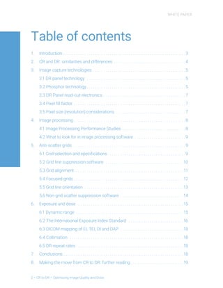
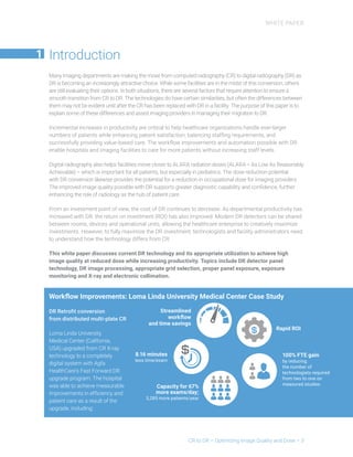
Workflow Improvements: Loma Linda University Medical Center Case Study
DR Retrofit conversion
from distributed multi-plate CR
Loma Linda University
Medical Center (California,
USA) upgraded from CR X-ray
technology to a completely
digital system with Agfa
HealthCare’s Fast Forward DR
upgrade program. The hospital
was able to achieve measurable
improvements in efficiency and
patient care as a result of the
upgrade, including:
1
8.16 minutes
less time/exam
Streamlined
workflow
and time savings
100% FTE gain
by reducing
the number of
technologists required
from two to one on
measured studies
Capacity for 67%
more exams/day;
3,285 more patients/year
Rapid ROI
WHITE PAPER
4 – CR to DR – Optimizing Image Quality and Dose
CR and DR: similarities and differences
CR and DR both use a standard X-ray generator. With CR, the X-rays are captured using a photostimulable
phosphor (PSP) plate in a cassette. After the X-ray exposure, the cassette is placed in a special scanner/
reader where the latent image is retrieved pixel by pixel, and digitized. The result is an extremely accurate
image that appears on the CR workstation 30 to 60 seconds after the PSP plate is scanned.
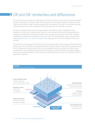
DR captures images directly, using a flat panel detector. DR detectors may be integrated into the
equipment or they may be “cassette sized” (and most often wireless) to work with existing analog X-ray
equipment. DR detectors completely eliminate the step of digitizing the image in a CR reader. Instead, a
scintillator in the DR panel immediately converts the X-rays into visible light that is then converted into a
digital signal (see figure 1 for additional details). The image appears on the DR workstation in just a few
seconds.
Today, there are a broad range of DR units to fit the needs and budget of every imaging facility. Retrofit DR
panels, which come in different sizes and phosphor technologies, enable “Instant DR” by upgrading analog
film or CR-based X-ray systems to DR. DR rooms are available with floor mounted X-ray tubes, ceiling
mounted tubes, and radiography/fluoroscopy (R/F) DR systems, while mobile DR units enable imaging to
be done at the patient bedside in critical care units. Analog mobile units can also be retrofitted with DR to
extend their useful life.
2 
FIGURE 1
DR panel image capture technology
X-ray scintillator screen
Contains phosphors
which convert X-Rays to light
Electronic control
Triggers the
TFT switches
Readout electronics
Capture and amplify
the electronic signals
TFT switching circuit
Connects each pixel
to readout device
TFT array
Collects charges
from photodiodes
Photodiode layer
Collects light and converts
it into electric charges
Analog-to-digital
conversion
WHITE PAPER
 CR to DR – Optimizing Image Quality and Dose – 5
Image capture technologies
The choice of panel and phosphor technologies can facilitate improved image quality and a dose
reduction of up to 60%, so careful selection is critical.
3.1 DR PANEL TECHNOLOGY
DR uses flat panel detectors to capture images. First, X-rays are absorbed in a phosphor screen layer, inside the
flat panel detector. The X-rays are then converted into visible light. A photodiode converts this light into photo-
charges that are collected via the active matrix TFT sensor of the flat panel detector, creating a signal from each
pixel. These signals are amplified, digitized, processed and sent to the acquisition workstation. From the DR
acquisition station, they are sent to a display, distribution and archival system (commonly referred to as a picture
archive and communication system, or PACS). The digital image can be displayed on a monitor or a hardcopy
image can be printed.
3.2 PHOSPHOR TECHNOLOGY
For both CR and DR, image quality is impacted by the phosphor technology used to convert the X-ray
energy into light. Either powder phosphors (the ‘traditional’ technology) or needle phosphors (the high-
efficiency choice) can be used. CR may use powder phosphors composed of Barium Fluoride Bromide
(BaFBr) or needle phosphors composed of Cesium Bromide (CsBr)1
. See figure 2.
For DR, the scintillation layer of the detector can also be made of powder phosphor composed of Gadolinium
Oxysulfide (GOS or Gadox) or needle phosphors composed of Cesium Iodide (CsI). See figure 2.
To give an example of how the selection of phosphor technology makes a difference: for a high level of X-ray
absorption in the phosphor layer, a thick phosphor layer is needed. When using a powder phosphor, light
scattering in the phosphor layer reduces the sharpness, limiting the image quality. The optimum compromise
of resolution and X-ray absorption is reached for a layer thickness of less than ~300 ”m. With a needle
phosphor however, a thicker phosphor layer can be used without jeopardizing the sharpness due to the low
light scattering. With needle phosphor technology, higher X-ray absorption is possible, resulting in lower dose
and better image quality (i.e.) higher detective quantum efficiency or DQE*). A CsI needle phosphor in a DR
system of ~500 ”m thickness can have up to 50% more X-ray absorption than a powder phosphor.**
3
FIGURE 2
Needle phosphors reduce light scattering and improve image quality
CR-BaFBr DR-Csl
300”
500”
*	 Detective quantum efficiency (DQE) is a measure of the ability of the imaging system to preserve the signal-to-noise ratio
from the radiation field to the resulting digital image, and thus of the combined effect of sharpness and noise performance.
This value is generally accepted as the best measure of overall performance of imaging detectors in medical radiography.
**	 CR systems with CsBr needle phosphor plates can achieve similar results, when compared to BaFBr phosphor CR systems.
1
	 Leblans P.J.R. Vandenbroucke D.A.N., Willems P. “Storage Phosphors for Medical Imaging”, Materials 4(6):1034-
1086 · December 2011. DOI: 10.3390/ma4061034
WHITE PAPER
6 – CR to DR – Optimizing Image Quality and Dose
It is important to note that even though Cesium Iodide detectors normally reduce dose compared to
powder phosphor technology, not all CsI phosphors are the same. Some manufacturers offer less
expensive CsI detectors for the market segments where dose and image quality are secondary to price.
These CsI detectors may use thinner phosphor layers with lower quality phosphors.
3.3 DR PANEL READ-OUT ELECTRONICS
During the read-out process, driver electronics, amplifiers, multiplexers and analog-to-digital convertors
can introduce additional pixel noise. Recent designs of these active components have enhanced noise
management properties, improving image quality at lower doses and allowing for further dose reduction.
3.4 PIXEL FILL FACTOR
Each pixel in a DR detector has an active sensing area (photodiode) and a switching circuit. The “fill factor”
(FF) is the percentage of the pixel that makes up the active sensing area.
Lower quality sensors with larger switching circuits (TFT – thin film transistor) and lines will have lower fill
factors and less active area within each pixel. DR panels with lower fill factors result in lower efficiency and
thus higher image noise and lower overall image quality, compared to DR panels with smaller switching
circuits and better fill factors (see figure 3).
3.5 PIXEL SIZE (RESOLUTION) CONSIDERATIONS
When selecting a DR panel, choosing the appropriate pixel size (sometimes referred to as ‘pixel pitch’) is
important. Factors that should be considered include the type of examination being done (pediatric, adult,
extremities), the dose requirements and the image quality needs.
Needle Cesium Iodide (CsI) phosphors technology (figure 2):
 
  Enable thicker phosphor layers
 
  Significantly reduce internal light scatter
 
  Improve image sharpness
 
  Improve X-ray absorption
 
  Reduce dose by approximately 50%
 
  Improve image quality
WHITE PAPER
 CR to DR – Optimizing Image Quality and Dose – 7
FIGURE 3
At equal resolution, the smaller switching circuit area (TFT) in pixel B
will result in a larger active area with better DQE and better overall image quality than pixel A
Row line
Photodiode
Data line
Bias line
TFT switch
One pixel
One pixel
Pixel A = Pixel B in “Resolution”
but not in image quality
 Switching circuit area of
Pixel A  Pixel B
 Active area of Pixel B  Pixel A
 Thus fill factor and DQE of
Pixel B  Pixel A
Scintilator
Pixel A Pixel B
Photodiode
Switching circuit
While smaller pixel sizes have potential for higher resolution, larger pixel sizes usually have a higher fill factor
and thus a higher collection efficiency. Due to the larger pixel area, more X-ray photons per pixel contribute
to the pixel value, resulting in lower quantum noise. Pixel sizes that are smaller than the resolution
needed for a given examination may actually increase the noise in the image depending on the type of
technology utilized. Using a larger (appropriate) pixel size that still meets the resolution requirements of
the examination can reduce visible noise in the image and offers the potential to lower patient dose.
WHITE PAPER
8 – CR to DR – Optimizing Image Quality and Dose
Image processing
4.1 IMAGE PROCESSING PERFORMANCE STUDIES
Studies have demonstrated that image processing can significantly affect perceived image quality at
reduced dose. Multi-scale image processing can improve usable diagnostic information at lower doses2
.
(see figure 4). Fractional Multi-scale Processing (FMP) with active noise reduction, provides the potential
for further reductions in dose3
.
4
FIGURE 4
MUSICA multi-scale image processing can improve image quality and reduce dose
2
	 Sensakovic W.F., O’Dell M.C., Letter H., Kohler N., Rop B., Cook J., Logsdon G., Varich L. Image quality and dose differences
caused by vendor-specific image processing of neonatal radiographs. Pediatr Radiol. 2016 Oct;46(11):1606-13. doi: 10.1007
s00247-016-3663-2. Epub 2016 Aug 3.
3
	 Vandenbroucke D.A.N., Apgar B.K., Bertens T. Optimizing Patient Dose. Agfa HealthCare White Paper Dec 2014
Fractional Multiscale Processing (FMP)
FMP is the mathematical substructure of Agfa HealthCare’s latest MUSICA image processing
software, which further decomposes image components into elementary fractions for separate
processing. FMP results in a more accurate multi-scale enhancement model, a balanced
participation of all filter kernel pixels in the enhancement process, and better preservation of
high-resolution, low-contrast details next to high-contrast structures.
Image processing can improve usable diagnostic information at lower dose
Standard
processing
14”Gy Multi-scale neonatal
processing
WHITE PAPER
 CR to DR – Optimizing Image Quality and Dose – 9
4.2 WHAT TO LOOK FOR IN IMAGE PROCESSING SOFTWARE
Image processing software should provide consistent performance, for all body types and patient ages
(neonatal, pediatric, adult, bariatric, etc.), over a wide range of exposure factors. It should not create
artifacts, should be tolerant of over and underexposure, and should especially be low-dose friendly.
The software should increase productivity: reducing, not increasing, work for radiology staff. This means
little to no post-processing, automatic window/level adjustments, automatic electronic masking and
excellent area of interest (AOI) accuracy. Configuration and set-up should be easy: the software should
work well out of the box with little or no ongoing maintenance, include simple and understandable
adjustment settings, and avoid complex parameter adjustments that require set-up and maintenance by
imaging specialists.
Anti-scatter grids
5.1 GRID SELECTION AND SPECIFICATIONS
Grid performance factors can also have a significant impact on the digital image. Some of the most
important factors include:
 
  Grid ratio – impacts image quality
 
  Bucky factor, or the amount by which the exposure must be increased or decreased when using a grid
– impacts dose
 
  Reciprocating (moving) versus stationary – impacts visibility of gridlines
(it is important that the gridlines are not visible)
 
  Line rate (frequency) (in lines/cm or inch) – impacts artifact minimization
 
  Focal distance – impacts artifact minimization and grid cut off
 
  Grid positioning, including angle and distance – impacts image quality
 
  Grid line direction – impacts positioning flexibility
5
FIGURE 5
Example of anti-scatter grid label displaying specifications
WHITE PAPER
10 – CR to DR – Optimizing Image Quality and Dose
5.2 GRID LINE SUPPRESSION SOFTWARE
Most newer DR systems use stationary grids instead of reciprocating grids. To remove grid lines from
the final image, grid line suppression software (GLS) is used. Grid line suppression software automatically
identifies repeating patterns caused by the grid-panel interference, and removes them. The result is
improved viewing conditions and workflow options.
To ensure the grid line suppression software works correctly, it is important to follow the manufacturer’s
recommendations when selecting a grid. The pixel pitch of the panel, the grid type and lines per inch can
influence the appearance of grid lines. Improper grid selection may result in image artifacts caused by
the interference between the DR panel and grid (see images, figure 6). The chart below (figure 7) shows
the results of an image quality evaluation using Agfa HealthCare’s GLS grid line suppression software
in combination with different DR and CR plates and grid specifications. The best results are indicated in
green font.
FIGURE 6
Grid line artifacts
(aliasing or moiré patterns)
Grid line suppression software
removes artifacts
WHITE PAPER
 CR to DR – Optimizing Image Quality and Dose – 11
Agfa HealthCare DR Panel Type
Grid Line
Frequency
DR 10S/14S DX-D 30/35C DX-D 40C DX-D 45C
CR Plate
100 to 150 micron
32 lines/cm
80 lines/inch
Poor results
Not recommended
Poor results
Not recommended
Poor results
Not recommended
Poor results
Not recommended
Poor results
Not recommended
36 lines/cm
90 lines/inch
Poor results
Not recommended
Poor results
Not recommended
Poor results
Not recommended
Poor results
Not recommended
Good Results
Acceptable for use
40 lines/cm
103 lines/inch
Good Results
Acceptable for use
Good Results
Acceptable for use
Good Results
Acceptable for use
Good Results
Acceptable for use
Poor results
Not recommended
50 lines/cm
132 lines/inch
Best results
Recommended for use
Best results
Recommended for use
Best results
Recommended for use
Best results
Recommended for use
Better results
Recommended for use
70 lines/cm
178 lines/inch
Poor results
Not recommended
Poor results
Not recommended
Poor results
Not recommended
Poor results
Not recommended
Best results
Recommended for use
80 lines/cm
215 lines/inch
Better results
Recommended for use
Better results
Recommended for use
Better results
Recommended for use
Better results
Recommended for use
Better results
Recommended for use
5.3 GRID ALIGNMENT
Incorrect grid alignment can lead to poor image quality. This is a common problem in portable/bedside
imaging and can be the source of many image quality complaints. Correct grid alignment requires
the angle of the tube/collimator to be the same as that of the grid/panel. The tube/collimator should be
parallel to the plane of the anti-scatter grid and the appropriate distance used for the recommended grid
type. Improper alignment will result in increased scatter, grid cut-off and overall poor image quality.
FIGURE 7
Agfa HealthCare recommended grid lines/cm for various resolution CR plates and DR Panels
FIGURE 8
Proper tube distance and angle is required relative to the grid used to achieve correct image quality
Distance OK
Tube centered
Too high
Tube centered
Too low
Tube centered
Distance OK
Tube offset
Too high
Tube offset
WHITE PAPER
12 – CR to DR – Optimizing Image Quality and Dose
5.4 FOCUSED GRIDS
Some grids are labelled as ‘multi-focus’, providing a focal range rather than a single focal distance. This
focal range is always a compromise; the actual focus falls somewhere within the range. At the extremes
of the range, the image will experience grid cut-off and grid lines may be visible at the edges of the image
(see figure 8). Many DR systems offer multiple grid options depending on the distance required for the
examination (Figure 11).
FIGURE 9
Tube collimator and grid are NOT properly aligned (not
parallel). This results in increased scatter causing poor
lung and spine detail
FIGURE 10
Tube collimator and grid are properly aligned.
This results in good scatter removal with excellent
image detail
FIGURE 11
For the best results, use the
correct SID and anti-scatter grid
with the right focal distance for
the exam.
For example: 72 inches for chest
imaging, 40 inches for abdomen,
spine, shoulders etc.
100 cm / 40 inches
150 cm / 60 inches
180 cm / 72 inches
WHITE PAPER
 CR to DR – Optimizing Image Quality and Dose – 13
5.5 GRID LINE ORIENTATION
 
  Most stationary grids used in portable/mobile radiography are the same size as the DR panel being used.
 
  Grid lines are often oriented along the long dimension, but may be oriented along the short dimension
(aka “decubitus” grids). Decubitus grids may be preferable for chest images done with the detector in
the landscape orientation.
 
  Grids in tables and upright buckys are usually 17-20” square grids.
5.6 NON-GRID SCATTER SUPPRESSION SOFTWARE
Although the use of grids is optimal from a physics standpoint, as previously stated, when using a grid
several items must be monitored to ensure proper image quality.
 
  Grids need to be properly centered and positioned to improve image quality. If they are not,
they can actually reduce image quality and this can easily occur during mobile radiography.
 
  Grids can become damaged over time.
 
  Grids may create artifacts in the images (known as aliasing or moiré patterns).
 
  Grids typically require a higher radiation dose.
 
  Grids may require longer exposure times.
 
  Grids add weight to the detector and increase muscle strain for technologists,
especially during bedside/portable radiography.
Because of the time and effort required, in certain cases it may be preferable to avoid using grids,
for example in bedside chest imaging.
FIGURE 12
Grid line orientation
Typical grid line
orientation
“Portrait”
“Decubitus”
grid line orientation
Square table or upright
bucky grid
WHITE PAPER
14 – CR to DR – Optimizing Image Quality and Dose
Recently “non-grid” scatter suppression software has become available which uses advanced image
processing to reduce (not eliminate) the need for a grid. Since scatter radiation is primarily visible in the
low frequency component of an image, scatter suppression software extracts the low frequency scatter
information from the image, while enhancing the medium to high frequencies in the image. This results in
enhancement of the relevant clinical information while reducing the visualization of scatter. For example,
scatter suppression software can improve lung field detail without the use of an anti-scatter grid.  
Scatter suppression software may also be used with a grid in some cases, to provide the best overall
result, for example with bariatric patients. In these cases, high amounts of scatter can be present in the
image even when using a grid, depending on the patient size. Thus, scatter suppression software can
improve image quality.
When using scatter suppression software, each department should establish guidelines for the
appropriate use (or not) of grids, particularly with mobile or portable examinations. The patient type
(pediatric, normal or bariatric) should be considered, as well as the examination criteria (such as ruling out
foreign bodies or providing more prominent visualization of catheters and fine needles) when determining
what type of grid and image processing should be used.
While a grid will increase image quality, grid techniques require proper positioning and a higher overall
dose (up to 50% increase), compared to non-grid exposures.
FIGURE 13
Non-grid chest with standard processing Non-grid chest with MUSICA Chest+ software
WHITE PAPER
 CR to DR – Optimizing Image Quality and Dose – 15
In summary, image processing software may be able to eliminate the need for a grid with DR depending on:
 
  The application: mobile or in-room
 
  The patient size/type: pediatric, normal, obese, bariatric, etc.
 
  The workflow requirements: grid + panel weight and correct alignment, SID
 
  The examination criteria: image quality, dose
Generally, “non-grid” image processing should be seen as an option in the DR “toolbox”. It should be
considered and used when appropriate in order to improve image quality and workflow, and reduce dose.
Exposure and dose
6.1 DYNAMIC RANGE
DR images can offer higher contrast and sharpness. DR panels also normally require less exposure (dose)
to achieve equal or better image quality, especially with cesium-based detectors. However, there is
significantly less exposure latitude with DR because of the smaller dynamic range compared to CR.
The dynamic range is the ratio between the highest exposure level without saturation artifacts and the
lowest exposure level detectable above the intrinsic noise level. CR typically has a dynamic range of
approximately 10,000:1. The dynamic range of DR systems is about 200:1 for older systems, and up to
1500:1 for newer, 16-bit systems. Traditional film screen systems have a dynamic range of about 25:1.
Thus, DR systems offer a larger dynamic range than film screen systems, but a much smaller range than
CR systems.
The exposure latitude of a system indicates to what degree the mAs can be changed from the ideal
exposure for a single patient, and still achieve acceptable image quality. The exposure latitude depends
on the type of system used (film, CR or DR), the dynamic range of that system, and the type of body part
being imaged. The acceptable exposure latitude is often expressed as the change in milli-amperage
seconds or mAs, which corresponds to a change in dose.
The exposure latitude of a CR system is much greater than that of a DR or film screen system. For
example, for a lateral skull examination, CR typically has an acceptable exposure range of -4X mAs to
+16X mAs (or more). DR has an acceptable exposure range of about ±4X mAs from the ideal exposure.
A DR exposure variation greater than +4X mAs can result in image saturation, and the data is not usually
recoverable. Therefore, with DR systems, great attention must be paid to exposure accuracy in order to
prevent image saturation and overexposure (see figure 14).
6
WHITE PAPER
16 – CR to DR – Optimizing Image Quality and Dose
6.2 THE INTERNATIONAL EXPOSURE INDEX STANDARD
In 2008 the International Electrotechnical Commission (IEC) published the IEC 62494-1 standard,
“Exposure index of digital X-ray imaging systems”. It outlines a methodology for monitoring exposure
consistency within an exam type, and provides a standard way to measure the exposure to a digital
detector.
The index consists of three values: Exposure Index (EI), Target Exposure Index (TEI) and
Deviation Index (DI)4
.
 
  The Exposure Index (EI) is related to the exposure reaching the receptor. If the mAs is doubled, the
exposure index is doubled; if the mAs is halved, the EI is also halved. The relationship is therefore
linear under all conditions. The EI is a relative exposure measurement, within each exam type. It is not
intended (and should not be used) as a calibrated dose meter or a measurement of dose. To confirm the
performance of the exposure index, a flat field exposure can be made with a calibrated (RQA-5) beam. The
IEC standard indicates that the exposure index results should fall within ± 20% under these conditions.
 
  The Target Exposure Index (TEI) is the reference (e.g. ideal) exposure index for a particular examination
view. Various exams will have different TEI values, depending on the detector type and image quality
needs. For example, the TEI for extremities may be 900; for chest, the TEI may be 250; an abdominal
TEI may be 350; etc. The TEI is used to calculate the Deviation Index (DI).
	 The goal when selecting the TEI should be to achieve acceptable image quality at the lowest possible
dose (ALARA). Lower TEI values will require less dose, but will reduce image quality. Once a TEI value is
selected, individual EI values may fall outside of these ranges due to normal variations in exposure.
FIGURE 14
DR panel saturation at high exposure
CR 70 kVp 160 mAs DR 70 kVp 160 mAs
4
	 Don Steven, Whiting Bruce R., Rutz Lois Jo, Apgar Bruce K. New Exposure Indicators for Digital Radiography Simplified for
Radiologists and Technologists. American Journal of Roentgenology. Dec 2012
WHITE PAPER
 CR to DR – Optimizing Image Quality and Dose – 17
The TEI can be set by an applications specialist with input and recommendations from the hospital, or
can be determined based on the average of a number of exposures. The TEI should never be changed
based on a single image exposure, but rather on statistics from multiple exposures. Check with your
manufacturer for initial TEI recommendations.
Examination
General work
(chest, abdomen, etc)
Shoulders, spines* Extremities
Detector
type
Starting
point
Min. Max.
Starting
point
Min. Max.
Starting
point
Min. Max.
DR-Csl
(needle)
350 150 500 450 200 800 700 400 1000
DR-GOS
(powder)
700 300 1000 900 400 1600 1400 800 2000
*If the image quality is acceptable, lower TEI values (100 to 150) may be used on repeated scoliosis studies to minimize dose.
 
  The Deviation Index (DI) expresses how far a single exposure is from the TEI (the reference). It thus
provides a relative indication of under or overexposure. The DI is equal to 10x the logarithm of the ratio
of EI for a given exam view to the TEI for the exam view. One deviation unit equals ~25% (+1 or -1) over
or underexposure (similar to an automatic exposure control (AEC)). Three deviation units equals 2x or
Âœx of the target exposure (+3 or -3). While in a perfect world, DI would be 0, this is of course rarely the
case. Studies have shown that when the TEI is properly selected, 90 - 95% of the deviation index values
fall within -3 to +3 deviation units from the target for manual exposures and -2 to +2 deviation units
for AEC exposures. On the Agfa HealthCare DR acquisition station, dose monitoring software must be
active to display DI and TEI values and the associated color-coded graphic on the image.
FIGURE 15
Agfa HealthCare’s suggested Target Exposure Index (TEI) starting points for various examinations and Agfa
HealthCare DR panel types (CsI or GOS). The final TEI values used should be determined by the imaging
requirements of the radiologists, and normally should be somewhere between the minimum and maximum
values shown.
FIGURE 16
Exposure Index with Deviation Index display
Exposure Monitoring Software
Exposure Monitoring Software includes a color-
coded exposure (dose) bar that indicates how far
the image EI is from the TEI: the dose bar is green
when on/near the target EI, turns yellow when
over/underexposed by a factor of 2 and red when
over/underexposed by a factor of 4 (see graphic
display). While the bar gives a relative indication of
the exposure to the plate, and is a good measure
of the variation of the exposure to the plate
within a given exam type, it is not an absolute
measurement of patient dose or absorbed dose.
Overexposed far
outside the range
Greather than
4X exposure
Greater than 6.0 DI
Red significantly
overexposed
WHITE PAPER
18 – CR to DR – Optimizing Image Quality and Dose
FIGURE 17
Proper automatic image collimation
6.3 DICOM MAPPING OF EI, TEI, DI AND DAP
The EI, TEI, DI and DAP values can be displayed on the PACS workstation using the appropriate DICOM
tags. The DICOM committee has defined the following tags for EI, TEI, DI and DAP (Dose Area Product):
 
  EI: (0018,1411)
 
  TEI: (0018,1412)
 
  DI: (0018,1413)
 
  DAP: (0018,115E)
6.4 COLLIMATION
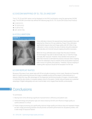
X-ray collimation reduces the exposed area, lowering patient dose and
reducing the influence of X-ray scattering. Proper X-ray collimation
significantly impacts dose and image quality with DR. When X-ray
collimation is done correctly, the area of interest should be detected
automatically, and minimal manual cropping should be necessary.
When the X-ray collimated area is larger than the area of interest,
the technologist may wish to electronically crop or mask the image
manually after exposure. However, many facilities have policies in
place that minimize or eliminate this practice, because when cropping
is done the radiologist may be unaware of the actual patient exposure,
both in terms of quantity and anatomy. Therefore, manual cropping or
masking after exposure should be the exception not the rule.
6.5 DR REPEAT RATES
Because of the ease of use, repeat rates with DR are actually increasing in some cases. Repeats are frequently
taken to modify positioning because the image is available quickly and the patient is still positioned on a
detector. While this may offer advantages for the diagnostic and technical quality of images, it should be kept
in mind that this also results in increased radiation dose for the patient. Overall, reduced repeats are a potential
advantage of digital radiography, and care must be taken not to negate these benefits unnecessarily.
Conclusions
To summarize,
1.	 Moving from CR to DR brings significant improvements in efficiency and patient care
2.	Panel technology and phosphor type can reduce dose by 50-60% and influence image quality, so
careful selection is critical.
3.	Proper image processing can significantly improve image quality and reduce dose and repeated images
as well. Image processing software should provide consistent performance for all patient profiles, over
a wide range of exposure factors.
 7
WHITE PAPER
 CR to DR – Optimizing Image Quality and Dose – 19
4.	Anti-scatter grids and their correct positioning can improve image quality. The required specifications
for grids used for DR may be different than for CR. Therefore, check with your manufacturer.
Depending on the examination, it may be preferable to avoid using anti-scatter grids. “Non-grid” scatter
suppression software can reduce the need for anti-scatter grids in many cases.
5.	Proper technique selection is more important than ever. The dynamic range of DR is lower than that of
CR, so DR images can be saturated and unrecoverable in some cases. DR systems should fully conform
to the IEC Exposure Index standard to insure proper monitoring and control of exposure.
6.	X-ray collimation influences scatter, image processing and overall image quality. Improper electronic
collimation, cropping or masking to correct for poor X-ray collimation reduces image quality, increases
patient dose, and may be against the healthcare facility policy. Certainly, manual masking/cropping is
not a best practice!
Making the move from CR to DR:
further reading
ASRT white paper: Best Practices in Digital Radiography
https://www.asrt.org/docs/default-source/publications/whitepapers/asrt12_bstpracdigradwhp_final.pdf
ASRT article: Radiation Safety Compliance
https://media.asrt.org/pdf/publications/RADT_Vol87_No5_CT.pdf (see page 511 and further)
Agfa HealthCare white paper: Optimizing Patient Dose
http://www.agfahealthcare.com/global/en/he/library/libraryopen?ID=47689266
Agfa HealthCare white paper: Non-grid Bedside Chest Imaging
http://global.agfahealthcare.com/int/non-grid-bedside-chest-imaging-white-paper/
About the authors:
Bruce Apgar is based in Greenville, South Carolina (USA). As Agfa HealthCare’s application lead for imaging
services, he is one of the company’s leading experts on dose reduction issues, especially in neonatal and pediatric
environments. He represents the company, and its views, at several leading technical committees, including
the task groups of the American Association of Physicists in Medicine (AAPM), and at the Medical Imaging and
Technology Alliance (MITA). He has a B.S. in Imaging Science from Rochester Institute of Technology.
George Curley RT(R) has been with Agfa HealthCare for 25 years. He is currently Senior Sales Marketing
Manager of Digital Imaging Products for North America. He is a radiographer and former radiology
manager with extensive experience in digital imaging clinically and commercially.
Dirk Vandenbroucke is an RD scientist investigating innovative technologies for Agfa HealthCare’s
medical imaging systems. As a senior researcher, he has contributed to the fundamental research
in conventional silver halide film screen systems and in the development of CR and DR systems. He
is an active member of various working groups in international standard committees (ISO, IEC). Dr.
Vandenbroucke has a PhD in physics from the University of Ghent.
8
Agfa HealthCare, present in one hospital out of two, is a leading provider of
eHealth  Digital Imaging solutions. Care organizations in over 100 countries
rely on Agfa HealthCare to optimize their efficiency and improve patient care.
Agfa, the Agfa rhombus and MUSICA are trademarks of Agfa-Gevaert N.V., Belgium, or its affiliates.
All other trademarks are held by their respective owners and are used in an editorial fashion with no intention
of infringement. The data in this publication are for illustration purposes only and do not necessarily represent
standards or specifications, which must be met by Agfa HealthCare. All information contained herein is intended
for guidance purposes only, and characteristics of the products and services described in this publication
can be changed at any time without notice. Products and services may not be available for your local area.
Please contact your local sales representative for availability information. Agfa HealthCare diligently strives to
provide as accurate information as possible, but shall not be responsible for any typographical error.
Copyright 2017
Agfa HealthCare NV
All rights reserved
Published by Agfa HealthCare NV
B-2640 Mortsel – Belgium
GB 201709

More Related Content

What's hot

Image Quality, Artifacts and it's Remedies in CT-Avinesh Shrestha
Image Quality, Artifacts and it's Remedies in CT-Avinesh ShresthaImage Quality, Artifacts and it's Remedies in CT-Avinesh Shrestha
Image Quality, Artifacts and it's Remedies in CT-Avinesh ShresthaAvinesh Shrestha
 
Cone beam computed tomography (2)
Cone beam computed tomography (2)Cone beam computed tomography (2)
Cone beam computed tomography (2)Mohit Kapoor
 
Image reconstruction in nuclear medicine
Image reconstruction in nuclear medicineImage reconstruction in nuclear medicine
Image reconstruction in nuclear medicineshokoofeh mousavi
 
Comparison of film sensitivity with epid for different doses.
Comparison of film sensitivity with epid for different doses.Comparison of film sensitivity with epid for different doses.
Comparison of film sensitivity with epid for different doses.Jyoti Bisht
 
Tube and Line and Pneumothorax Visualization Software
Tube and Line and Pneumothorax Visualization SoftwareTube and Line and Pneumothorax Visualization Software
Tube and Line and Pneumothorax Visualization SoftwareCarestream
 
Rician Noise Reduction with SVM and Iterative Bilateral Filter in Different T...
Rician Noise Reduction with SVM and Iterative Bilateral Filter in Different T...Rician Noise Reduction with SVM and Iterative Bilateral Filter in Different T...
Rician Noise Reduction with SVM and Iterative Bilateral Filter in Different T...IJMERJOURNAL
 
Bone Suppression for Chest Radiographic Images
Bone Suppression for Chest Radiographic ImagesBone Suppression for Chest Radiographic Images
Bone Suppression for Chest Radiographic ImagesCarestream
 
Image Quality - Radiologic Imaging
Image Quality - Radiologic ImagingImage Quality - Radiologic Imaging
Image Quality - Radiologic ImagingMaria Nicole Sicaja
 
Ct image quality artifacts and it remedy
Ct image quality artifacts and it remedyCt image quality artifacts and it remedy
Ct image quality artifacts and it remedyYashawant Yadav
 
äžŠæ”·ćż…ć’Œ Advancements in hyperspectral and multi-spectral imaè¶…ć…‰è°±é«˜ć…‰è°±ć€šć…‰è°±
äžŠæ”·ćż…ć’Œ Advancements in hyperspectral and multi-spectral imaè¶…ć…‰è°±é«˜ć…‰è°±ć€šć…‰è°±äžŠæ”·ćż…ć’Œ Advancements in hyperspectral and multi-spectral imaè¶…ć…‰è°±é«˜ć…‰è°±ć€šć…‰è°±
äžŠæ”·ćż…ć’Œ Advancements in hyperspectral and multi-spectral imaè¶…ć…‰è°±é«˜ć…‰è°±ć€šć…‰è°±algous
 
Chapter 6 image quality in ct
Chapter 6 image quality in ct Chapter 6 image quality in ct
Chapter 6 image quality in ct Muntaser S.Ahmad
 
Chapter 4 image display
Chapter 4 image displayChapter 4 image display
Chapter 4 image displayMuntaser S.Ahmad
 
EPID AND CBCT ON RADIATION THERAPY
EPID AND CBCT ON RADIATION THERAPYEPID AND CBCT ON RADIATION THERAPY
EPID AND CBCT ON RADIATION THERAPYanju k.v.
 
äžŠæ”·ćż…ć’Œ Advances-hyperspectral-imaging0409è¶…ć…‰è°±é«˜ć…‰è°±ć€šć…‰è°±
äžŠæ”·ćż…ć’Œ Advances-hyperspectral-imaging0409è¶…ć…‰è°±é«˜ć…‰è°±ć€šć…‰è°±äžŠæ”·ćż…ć’Œ Advances-hyperspectral-imaging0409è¶…ć…‰è°±é«˜ć…‰è°±ć€šć…‰è°±
äžŠæ”·ćż…ć’Œ Advances-hyperspectral-imaging0409è¶…ć…‰è°±é«˜ć…‰è°±ć€šć…‰è°±algous
 
Image reconstrsuction in ct pdf
Image reconstrsuction in ct pdfImage reconstrsuction in ct pdf
Image reconstrsuction in ct pdfmitians
 
Gamma Camera Image Quality
Gamma Camera Image QualityGamma Camera Image Quality
Gamma Camera Image QualityDavid Graff
 
Filtering Techniques to reduce Speckle Noise and Image Quality Enhancement me...
Filtering Techniques to reduce Speckle Noise and Image Quality Enhancement me...Filtering Techniques to reduce Speckle Noise and Image Quality Enhancement me...
Filtering Techniques to reduce Speckle Noise and Image Quality Enhancement me...IOSR Journals
 
Shadow Detection and Removal using Tricolor Attenuation Model Based on Featur...
Shadow Detection and Removal using Tricolor Attenuation Model Based on Featur...Shadow Detection and Removal using Tricolor Attenuation Model Based on Featur...
Shadow Detection and Removal using Tricolor Attenuation Model Based on Featur...ijtsrd
 
IJCER (www.ijceronline.com) International Journal of computational Engineerin...
IJCER (www.ijceronline.com) International Journal of computational Engineerin...IJCER (www.ijceronline.com) International Journal of computational Engineerin...
IJCER (www.ijceronline.com) International Journal of computational Engineerin...ijceronline
 

What's hot (20)

Image Quality, Artifacts and it's Remedies in CT-Avinesh Shrestha
Image Quality, Artifacts and it's Remedies in CT-Avinesh ShresthaImage Quality, Artifacts and it's Remedies in CT-Avinesh Shrestha
Image Quality, Artifacts and it's Remedies in CT-Avinesh Shrestha
 
Cone beam computed tomography (2)
Cone beam computed tomography (2)Cone beam computed tomography (2)
Cone beam computed tomography (2)
 
Image reconstruction in nuclear medicine
Image reconstruction in nuclear medicineImage reconstruction in nuclear medicine
Image reconstruction in nuclear medicine
 
Comparison of film sensitivity with epid for different doses.
Comparison of film sensitivity with epid for different doses.Comparison of film sensitivity with epid for different doses.
Comparison of film sensitivity with epid for different doses.
 
Tube and Line and Pneumothorax Visualization Software
Tube and Line and Pneumothorax Visualization SoftwareTube and Line and Pneumothorax Visualization Software
Tube and Line and Pneumothorax Visualization Software
 
Rician Noise Reduction with SVM and Iterative Bilateral Filter in Different T...
Rician Noise Reduction with SVM and Iterative Bilateral Filter in Different T...Rician Noise Reduction with SVM and Iterative Bilateral Filter in Different T...
Rician Noise Reduction with SVM and Iterative Bilateral Filter in Different T...
 
Bone Suppression for Chest Radiographic Images
Bone Suppression for Chest Radiographic ImagesBone Suppression for Chest Radiographic Images
Bone Suppression for Chest Radiographic Images
 
Image Quality - Radiologic Imaging
Image Quality - Radiologic ImagingImage Quality - Radiologic Imaging
Image Quality - Radiologic Imaging
 
Ct image quality artifacts and it remedy
Ct image quality artifacts and it remedyCt image quality artifacts and it remedy
Ct image quality artifacts and it remedy
 
äžŠæ”·ćż…ć’Œ Advancements in hyperspectral and multi-spectral imaè¶…ć…‰è°±é«˜ć…‰è°±ć€šć…‰è°±
äžŠæ”·ćż…ć’Œ Advancements in hyperspectral and multi-spectral imaè¶…ć…‰è°±é«˜ć…‰è°±ć€šć…‰è°±äžŠæ”·ćż…ć’Œ Advancements in hyperspectral and multi-spectral imaè¶…ć…‰è°±é«˜ć…‰è°±ć€šć…‰è°±
äžŠæ”·ćż…ć’Œ Advancements in hyperspectral and multi-spectral imaè¶…ć…‰è°±é«˜ć…‰è°±ć€šć…‰è°±
 
Chapter 6 image quality in ct
Chapter 6 image quality in ct Chapter 6 image quality in ct
Chapter 6 image quality in ct
 
Chapter 4 image display
Chapter 4 image displayChapter 4 image display
Chapter 4 image display
 
EPID AND CBCT ON RADIATION THERAPY
EPID AND CBCT ON RADIATION THERAPYEPID AND CBCT ON RADIATION THERAPY
EPID AND CBCT ON RADIATION THERAPY
 
SPECT
SPECTSPECT
SPECT
 
äžŠæ”·ćż…ć’Œ Advances-hyperspectral-imaging0409è¶…ć…‰è°±é«˜ć…‰è°±ć€šć…‰è°±
äžŠæ”·ćż…ć’Œ Advances-hyperspectral-imaging0409è¶…ć…‰è°±é«˜ć…‰è°±ć€šć…‰è°±äžŠæ”·ćż…ć’Œ Advances-hyperspectral-imaging0409è¶…ć…‰è°±é«˜ć…‰è°±ć€šć…‰è°±
äžŠæ”·ćż…ć’Œ Advances-hyperspectral-imaging0409è¶…ć…‰è°±é«˜ć…‰è°±ć€šć…‰è°±
 
Image reconstrsuction in ct pdf
Image reconstrsuction in ct pdfImage reconstrsuction in ct pdf
Image reconstrsuction in ct pdf
 
Gamma Camera Image Quality
Gamma Camera Image QualityGamma Camera Image Quality
Gamma Camera Image Quality
 
Filtering Techniques to reduce Speckle Noise and Image Quality Enhancement me...
Filtering Techniques to reduce Speckle Noise and Image Quality Enhancement me...Filtering Techniques to reduce Speckle Noise and Image Quality Enhancement me...
Filtering Techniques to reduce Speckle Noise and Image Quality Enhancement me...
 
Shadow Detection and Removal using Tricolor Attenuation Model Based on Featur...
Shadow Detection and Removal using Tricolor Attenuation Model Based on Featur...Shadow Detection and Removal using Tricolor Attenuation Model Based on Featur...
Shadow Detection and Removal using Tricolor Attenuation Model Based on Featur...
 
IJCER (www.ijceronline.com) International Journal of computational Engineerin...
IJCER (www.ijceronline.com) International Journal of computational Engineerin...IJCER (www.ijceronline.com) International Journal of computational Engineerin...
IJCER (www.ijceronline.com) International Journal of computational Engineerin...
 

Similar to Moving cr-to-dr

Im-ception - An exploration into facial PAD through the use of fine tuning de...
Im-ception - An exploration into facial PAD through the use of fine tuning de...Im-ception - An exploration into facial PAD through the use of fine tuning de...
Im-ception - An exploration into facial PAD through the use of fine tuning de...Cooper Wakefield
 
Man 00851 rev 001 understanding image checker 9.0
Man 00851 rev 001 understanding image checker 9.0Man 00851 rev 001 understanding image checker 9.0
Man 00851 rev 001 understanding image checker 9.0alex123123123
 
Data over dab
Data over dabData over dab
Data over dabDigris AG
 
1093012 l dailyqa3_ug_s
1093012 l dailyqa3_ug_s1093012 l dailyqa3_ug_s
1093012 l dailyqa3_ug_sRubén Quenhua
 
1093012 l dailyqa3_ug_s
1093012 l dailyqa3_ug_s1093012 l dailyqa3_ug_s
1093012 l dailyqa3_ug_sRubén Quenhua
 
論文
論文論文
論文monick hsieh
 
Masters' Thesis - Reza Pourramezan - 2017
Masters' Thesis - Reza Pourramezan - 2017Masters' Thesis - Reza Pourramezan - 2017
Masters' Thesis - Reza Pourramezan - 2017Reza Pourramezan
 
Venturini - X ray imaging for cheese
Venturini - X ray imaging for cheeseVenturini - X ray imaging for cheese
Venturini - X ray imaging for cheeseLorenzo Venturini
 
Docsis cmts receiver
Docsis cmts receiverDocsis cmts receiver
Docsis cmts receiverherooftit01
 
OFDM Based Cognitive radio
OFDM Based Cognitive radioOFDM Based Cognitive radio
OFDM Based Cognitive radioDeepesh Sinnya
 
Dissertation or Thesis on Efficient Clustering Scheme in Cognitive Radio Wire...
Dissertation or Thesis on Efficient Clustering Scheme in Cognitive Radio Wire...Dissertation or Thesis on Efficient Clustering Scheme in Cognitive Radio Wire...
Dissertation or Thesis on Efficient Clustering Scheme in Cognitive Radio Wire...aziznitham
 

Similar to Moving cr-to-dr (20)

main
mainmain
main
 
Im-ception - An exploration into facial PAD through the use of fine tuning de...
Im-ception - An exploration into facial PAD through the use of fine tuning de...Im-ception - An exploration into facial PAD through the use of fine tuning de...
Im-ception - An exploration into facial PAD through the use of fine tuning de...
 
Thesis
ThesisThesis
Thesis
 
AAPM-2005-TG18.pdf
AAPM-2005-TG18.pdfAAPM-2005-TG18.pdf
AAPM-2005-TG18.pdf
 
Man 00851 rev 001 understanding image checker 9.0
Man 00851 rev 001 understanding image checker 9.0Man 00851 rev 001 understanding image checker 9.0
Man 00851 rev 001 understanding image checker 9.0
 
Data over dab
Data over dabData over dab
Data over dab
 
1093012 l dailyqa3_ug_s
1093012 l dailyqa3_ug_s1093012 l dailyqa3_ug_s
1093012 l dailyqa3_ug_s
 
1093012 l dailyqa3_ug_s
1093012 l dailyqa3_ug_s1093012 l dailyqa3_ug_s
1093012 l dailyqa3_ug_s
 
Report
ReportReport
Report
 
論文
論文論文
論文
 
Thesis Report
Thesis ReportThesis Report
Thesis Report
 
thesis
thesisthesis
thesis
 
Masters' Thesis - Reza Pourramezan - 2017
Masters' Thesis - Reza Pourramezan - 2017Masters' Thesis - Reza Pourramezan - 2017
Masters' Thesis - Reza Pourramezan - 2017
 
T401
T401T401
T401
 
report
reportreport
report
 
Honours_Thesis2015_final
Honours_Thesis2015_finalHonours_Thesis2015_final
Honours_Thesis2015_final
 
Venturini - X ray imaging for cheese
Venturini - X ray imaging for cheeseVenturini - X ray imaging for cheese
Venturini - X ray imaging for cheese
 
Docsis cmts receiver
Docsis cmts receiverDocsis cmts receiver
Docsis cmts receiver
 
OFDM Based Cognitive radio
OFDM Based Cognitive radioOFDM Based Cognitive radio
OFDM Based Cognitive radio
 
Dissertation or Thesis on Efficient Clustering Scheme in Cognitive Radio Wire...
Dissertation or Thesis on Efficient Clustering Scheme in Cognitive Radio Wire...Dissertation or Thesis on Efficient Clustering Scheme in Cognitive Radio Wire...
Dissertation or Thesis on Efficient Clustering Scheme in Cognitive Radio Wire...
 

More from Maria Vergakh

00_master_document-KOY--πΔρÎčΔÎșτÎčÎșότητΔς ÎŽÎčÎ±Î»Ï…ÎŒÎŹÏ„Ï‰Îœ .pdf
00_master_document-KOY--πΔρÎčΔÎșτÎčÎșότητΔς ÎŽÎčÎ±Î»Ï…ÎŒÎŹÏ„Ï‰Îœ .pdf00_master_document-KOY--πΔρÎčΔÎșτÎčÎșότητΔς ÎŽÎčÎ±Î»Ï…ÎŒÎŹÏ„Ï‰Îœ .pdf
00_master_document-KOY--πΔρÎčΔÎșτÎčÎșότητΔς ÎŽÎčÎ±Î»Ï…ÎŒÎŹÏ„Ï‰Îœ .pdfMaria Vergakh
 
erotiseis_chem_c_gym .pdf
erotiseis_chem_c_gym                                 .pdferotiseis_chem_c_gym                                 .pdf
erotiseis_chem_c_gym .pdfMaria Vergakh
 
10. ΔπαΜαληπτÎčÎșÎŹ ΞέΌατα φυσÎčÎșÎź ÎČ΄Îșατ
10. ΔπαΜαληπτÎčÎșÎŹ ΞέΌατα φυσÎčÎșÎź ÎČ΄Îșατ10. ΔπαΜαληπτÎčÎșÎŹ ΞέΌατα φυσÎčÎșÎź ÎČ΄Îșατ
10. ΔπαΜαληπτÎčÎșÎŹ ΞέΌατα φυσÎčÎșÎź ÎČ΄ÎșατMaria Vergakh
 
1 2ÎșατΔύΞυΜση (2)
1 2ÎșατΔύΞυΜση (2)1 2ÎșατΔύΞυΜση (2)
1 2ÎșατΔύΞυΜση (2)Maria Vergakh
 

More from Maria Vergakh (11)

00_master_document-KOY--πΔρÎčΔÎșτÎčÎșότητΔς ÎŽÎčÎ±Î»Ï…ÎŒÎŹÏ„Ï‰Îœ .pdf
00_master_document-KOY--πΔρÎčΔÎșτÎčÎșότητΔς ÎŽÎčÎ±Î»Ï…ÎŒÎŹÏ„Ï‰Îœ .pdf00_master_document-KOY--πΔρÎčΔÎșτÎčÎșότητΔς ÎŽÎčÎ±Î»Ï…ÎŒÎŹÏ„Ï‰Îœ .pdf
00_master_document-KOY--πΔρÎčΔÎșτÎčÎșότητΔς ÎŽÎčÎ±Î»Ï…ÎŒÎŹÏ„Ï‰Îœ .pdf
 
erotiseis_chem_c_gym .pdf
erotiseis_chem_c_gym                                 .pdferotiseis_chem_c_gym                                 .pdf
erotiseis_chem_c_gym .pdf
 
10. ΔπαΜαληπτÎčÎșÎŹ ΞέΌατα φυσÎčÎșÎź ÎČ΄Îșατ
10. ΔπαΜαληπτÎčÎșÎŹ ΞέΌατα φυσÎčÎșÎź ÎČ΄Îșατ10. ΔπαΜαληπτÎčÎșÎŹ ΞέΌατα φυσÎčÎșÎź ÎČ΄Îșατ
10. ΔπαΜαληπτÎčÎșÎŹ ΞέΌατα φυσÎčÎșÎź ÎČ΄Îșατ
 
1 2ÎșατΔύΞυΜση (2)
1 2ÎșατΔύΞυΜση (2)1 2ÎșατΔύΞυΜση (2)
1 2ÎșατΔύΞυΜση (2)
 
Kef 5
Kef 5Kef 5
Kef 5
 
Kef 4
Kef 4Kef 4
Kef 4
 
Kef 3
Kef 3Kef 3
Kef 3
 
Kef 2
Kef 2Kef 2
Kef 2
 
Kef 1
Kef 1Kef 1
Kef 1
 
Eisagogh
EisagoghEisagogh
Eisagogh
 
Periexomena
PeriexomenaPeriexomena
Periexomena
 

Recently uploaded

Local Housewife and effective ☎ 8250192130 🍉🍓 Sexy Girls VIP Call Girls Chan...
Local Housewife and effective ☎ 8250192130 🍉🍓 Sexy Girls VIP Call Girls Chan...Local Housewife and effective ☎ 8250192130 🍉🍓 Sexy Girls VIP Call Girls Chan...
Local Housewife and effective ☎ 8250192130 🍉🍓 Sexy Girls VIP Call Girls Chan...Russian Call Girls Amritsar
 
Leading transformational change: inner and outer skills
Leading transformational change: inner and outer skillsLeading transformational change: inner and outer skills
Leading transformational change: inner and outer skillsHelenBevan4
 
pOOJA sexy Call Girls In Sector 49,9999965857 Young Female Escorts Service In...
pOOJA sexy Call Girls In Sector 49,9999965857 Young Female Escorts Service In...pOOJA sexy Call Girls In Sector 49,9999965857 Young Female Escorts Service In...
pOOJA sexy Call Girls In Sector 49,9999965857 Young Female Escorts Service In...Call Girls Noida
 
VIP Call Girls Hyderabad Megha 9907093804 Independent Escort Service Hyderabad
VIP Call Girls Hyderabad Megha 9907093804 Independent Escort Service HyderabadVIP Call Girls Hyderabad Megha 9907093804 Independent Escort Service Hyderabad
VIP Call Girls Hyderabad Megha 9907093804 Independent Escort Service Hyderabaddelhimodelshub1
 
Call Girl Raipur 9873940964 Book Hot And Sexy Girls
Call Girl Raipur 9873940964 Book Hot And Sexy GirlsCall Girl Raipur 9873940964 Book Hot And Sexy Girls
Call Girl Raipur 9873940964 Book Hot And Sexy Girlsddev2574
 
VIP Call Girl Sector 25 Gurgaon Just Call Me 9899900591
VIP Call Girl Sector 25 Gurgaon Just Call Me 9899900591VIP Call Girl Sector 25 Gurgaon Just Call Me 9899900591
VIP Call Girl Sector 25 Gurgaon Just Call Me 9899900591adityaroy0215
 
Hot Call Girl In Chandigarh đŸ‘…đŸ„” 9053'900678 Call Girls Service In Chandigarh
Hot  Call Girl In Chandigarh đŸ‘…đŸ„” 9053'900678 Call Girls Service In ChandigarhHot  Call Girl In Chandigarh đŸ‘…đŸ„” 9053'900678 Call Girls Service In Chandigarh
Hot Call Girl In Chandigarh đŸ‘…đŸ„” 9053'900678 Call Girls Service In ChandigarhVip call girls In Chandigarh
 
Vip Kolkata Call Girls Cossipore 👉 8250192130 âŁïžđŸ’Ż Available With Room 24×7
Vip Kolkata Call Girls Cossipore 👉 8250192130 âŁïžđŸ’Ż Available With Room 24×7Vip Kolkata Call Girls Cossipore 👉 8250192130 âŁïžđŸ’Ż Available With Room 24×7
Vip Kolkata Call Girls Cossipore 👉 8250192130 âŁïžđŸ’Ż Available With Room 24×7Miss joya
 
VIP Call Girls Sector 67 Gurgaon Just Call Me 9711199012
VIP Call Girls Sector 67 Gurgaon Just Call Me 9711199012VIP Call Girls Sector 67 Gurgaon Just Call Me 9711199012
VIP Call Girls Sector 67 Gurgaon Just Call Me 9711199012Call Girls Service Gurgaon
 
Call Girls Hyderabad Kirti 9907093804 Independent Escort Service Hyderabad
Call Girls Hyderabad Kirti 9907093804 Independent Escort Service HyderabadCall Girls Hyderabad Kirti 9907093804 Independent Escort Service Hyderabad
Call Girls Hyderabad Kirti 9907093804 Independent Escort Service Hyderabaddelhimodelshub1
 
Russian Call Girls in Raipur 9873940964 Book Hot And Sexy Girls
Russian Call Girls in Raipur 9873940964 Book Hot And Sexy GirlsRussian Call Girls in Raipur 9873940964 Book Hot And Sexy Girls
Russian Call Girls in Raipur 9873940964 Book Hot And Sexy Girlsddev2574
 
Call Girl Hyderabad Madhuri 9907093804 Independent Escort Service Hyderabad
Call Girl Hyderabad Madhuri 9907093804 Independent Escort Service HyderabadCall Girl Hyderabad Madhuri 9907093804 Independent Escort Service Hyderabad
Call Girl Hyderabad Madhuri 9907093804 Independent Escort Service Hyderabaddelhimodelshub1
 
Call Girls Secunderabad 7001305949 all area service COD available Any Time
Call Girls Secunderabad 7001305949 all area service COD available Any TimeCall Girls Secunderabad 7001305949 all area service COD available Any Time
Call Girls Secunderabad 7001305949 all area service COD available Any Timedelhimodelshub1
 
Basics of Anatomy- Language of Anatomy.pptx
Basics of Anatomy- Language of Anatomy.pptxBasics of Anatomy- Language of Anatomy.pptx
Basics of Anatomy- Language of Anatomy.pptxAyush Gupta
 
No Advance 9053900678 Chandigarh Call Girls , Indian Call Girls For Full Ni...
No Advance 9053900678 Chandigarh  Call Girls , Indian Call Girls  For Full Ni...No Advance 9053900678 Chandigarh  Call Girls , Indian Call Girls  For Full Ni...
No Advance 9053900678 Chandigarh Call Girls , Indian Call Girls For Full Ni...Vip call girls In Chandigarh
 
College Call Girls Hyderabad Sakshi 9907093804 Independent Escort Service Hyd...
College Call Girls Hyderabad Sakshi 9907093804 Independent Escort Service Hyd...College Call Girls Hyderabad Sakshi 9907093804 Independent Escort Service Hyd...
College Call Girls Hyderabad Sakshi 9907093804 Independent Escort Service Hyd...delhimodelshub1
 
Call Girl Chandigarh Mallika â€ïžđŸ‘ 9907093804 đŸ‘„đŸ«Š Independent Escort Service Cha...
Call Girl Chandigarh Mallika â€ïžđŸ‘ 9907093804 đŸ‘„đŸ«Š Independent Escort Service Cha...Call Girl Chandigarh Mallika â€ïžđŸ‘ 9907093804 đŸ‘„đŸ«Š Independent Escort Service Cha...
Call Girl Chandigarh Mallika â€ïžđŸ‘ 9907093804 đŸ‘„đŸ«Š Independent Escort Service Cha...High Profile Call Girls Chandigarh Aarushi
 
Call Girls LB Nagar 7001305949 all area service COD available Any Time
Call Girls LB Nagar 7001305949 all area service COD available Any TimeCall Girls LB Nagar 7001305949 all area service COD available Any Time
Call Girls LB Nagar 7001305949 all area service COD available Any Timedelhimodelshub1
 

Recently uploaded (20)

Local Housewife and effective ☎ 8250192130 🍉🍓 Sexy Girls VIP Call Girls Chan...
Local Housewife and effective ☎ 8250192130 🍉🍓 Sexy Girls VIP Call Girls Chan...Local Housewife and effective ☎ 8250192130 🍉🍓 Sexy Girls VIP Call Girls Chan...
Local Housewife and effective ☎ 8250192130 🍉🍓 Sexy Girls VIP Call Girls Chan...
 
Leading transformational change: inner and outer skills
Leading transformational change: inner and outer skillsLeading transformational change: inner and outer skills
Leading transformational change: inner and outer skills
 
pOOJA sexy Call Girls In Sector 49,9999965857 Young Female Escorts Service In...
pOOJA sexy Call Girls In Sector 49,9999965857 Young Female Escorts Service In...pOOJA sexy Call Girls In Sector 49,9999965857 Young Female Escorts Service In...
pOOJA sexy Call Girls In Sector 49,9999965857 Young Female Escorts Service In...
 
VIP Call Girls Hyderabad Megha 9907093804 Independent Escort Service Hyderabad
VIP Call Girls Hyderabad Megha 9907093804 Independent Escort Service HyderabadVIP Call Girls Hyderabad Megha 9907093804 Independent Escort Service Hyderabad
VIP Call Girls Hyderabad Megha 9907093804 Independent Escort Service Hyderabad
 
Call Girl Raipur 9873940964 Book Hot And Sexy Girls
Call Girl Raipur 9873940964 Book Hot And Sexy GirlsCall Girl Raipur 9873940964 Book Hot And Sexy Girls
Call Girl Raipur 9873940964 Book Hot And Sexy Girls
 
VIP Call Girl Sector 25 Gurgaon Just Call Me 9899900591
VIP Call Girl Sector 25 Gurgaon Just Call Me 9899900591VIP Call Girl Sector 25 Gurgaon Just Call Me 9899900591
VIP Call Girl Sector 25 Gurgaon Just Call Me 9899900591
 
Hot Call Girl In Chandigarh đŸ‘…đŸ„” 9053'900678 Call Girls Service In Chandigarh
Hot  Call Girl In Chandigarh đŸ‘…đŸ„” 9053'900678 Call Girls Service In ChandigarhHot  Call Girl In Chandigarh đŸ‘…đŸ„” 9053'900678 Call Girls Service In Chandigarh
Hot Call Girl In Chandigarh đŸ‘…đŸ„” 9053'900678 Call Girls Service In Chandigarh
 
Vip Kolkata Call Girls Cossipore 👉 8250192130 âŁïžđŸ’Ż Available With Room 24×7
Vip Kolkata Call Girls Cossipore 👉 8250192130 âŁïžđŸ’Ż Available With Room 24×7Vip Kolkata Call Girls Cossipore 👉 8250192130 âŁïžđŸ’Ż Available With Room 24×7
Vip Kolkata Call Girls Cossipore 👉 8250192130 âŁïžđŸ’Ż Available With Room 24×7
 
VIP Call Girls Sector 67 Gurgaon Just Call Me 9711199012
VIP Call Girls Sector 67 Gurgaon Just Call Me 9711199012VIP Call Girls Sector 67 Gurgaon Just Call Me 9711199012
VIP Call Girls Sector 67 Gurgaon Just Call Me 9711199012
 
Call Girls in Lucknow Esha 🔝 8923113531 🔝 đŸŽ¶ Independent Escort Service Lucknow
Call Girls in Lucknow Esha 🔝 8923113531  🔝 đŸŽ¶ Independent Escort Service LucknowCall Girls in Lucknow Esha 🔝 8923113531  🔝 đŸŽ¶ Independent Escort Service Lucknow
Call Girls in Lucknow Esha 🔝 8923113531 🔝 đŸŽ¶ Independent Escort Service Lucknow
 
Call Girls Hyderabad Kirti 9907093804 Independent Escort Service Hyderabad
Call Girls Hyderabad Kirti 9907093804 Independent Escort Service HyderabadCall Girls Hyderabad Kirti 9907093804 Independent Escort Service Hyderabad
Call Girls Hyderabad Kirti 9907093804 Independent Escort Service Hyderabad
 
Russian Call Girls in Raipur 9873940964 Book Hot And Sexy Girls
Russian Call Girls in Raipur 9873940964 Book Hot And Sexy GirlsRussian Call Girls in Raipur 9873940964 Book Hot And Sexy Girls
Russian Call Girls in Raipur 9873940964 Book Hot And Sexy Girls
 
Call Girl Hyderabad Madhuri 9907093804 Independent Escort Service Hyderabad
Call Girl Hyderabad Madhuri 9907093804 Independent Escort Service HyderabadCall Girl Hyderabad Madhuri 9907093804 Independent Escort Service Hyderabad
Call Girl Hyderabad Madhuri 9907093804 Independent Escort Service Hyderabad
 
Call Girls Secunderabad 7001305949 all area service COD available Any Time
Call Girls Secunderabad 7001305949 all area service COD available Any TimeCall Girls Secunderabad 7001305949 all area service COD available Any Time
Call Girls Secunderabad 7001305949 all area service COD available Any Time
 
Basics of Anatomy- Language of Anatomy.pptx
Basics of Anatomy- Language of Anatomy.pptxBasics of Anatomy- Language of Anatomy.pptx
Basics of Anatomy- Language of Anatomy.pptx
 
VIP Call Girls Lucknow Isha 🔝 9719455033 🔝 đŸŽ¶ Independent Escort Service Lucknow
VIP Call Girls Lucknow Isha 🔝 9719455033 🔝 đŸŽ¶ Independent Escort Service LucknowVIP Call Girls Lucknow Isha 🔝 9719455033 🔝 đŸŽ¶ Independent Escort Service Lucknow
VIP Call Girls Lucknow Isha 🔝 9719455033 🔝 đŸŽ¶ Independent Escort Service Lucknow
 
No Advance 9053900678 Chandigarh Call Girls , Indian Call Girls For Full Ni...
No Advance 9053900678 Chandigarh  Call Girls , Indian Call Girls  For Full Ni...No Advance 9053900678 Chandigarh  Call Girls , Indian Call Girls  For Full Ni...
No Advance 9053900678 Chandigarh Call Girls , Indian Call Girls For Full Ni...
 
College Call Girls Hyderabad Sakshi 9907093804 Independent Escort Service Hyd...
College Call Girls Hyderabad Sakshi 9907093804 Independent Escort Service Hyd...College Call Girls Hyderabad Sakshi 9907093804 Independent Escort Service Hyd...
College Call Girls Hyderabad Sakshi 9907093804 Independent Escort Service Hyd...
 
Call Girl Chandigarh Mallika â€ïžđŸ‘ 9907093804 đŸ‘„đŸ«Š Independent Escort Service Cha...
Call Girl Chandigarh Mallika â€ïžđŸ‘ 9907093804 đŸ‘„đŸ«Š Independent Escort Service Cha...Call Girl Chandigarh Mallika â€ïžđŸ‘ 9907093804 đŸ‘„đŸ«Š Independent Escort Service Cha...
Call Girl Chandigarh Mallika â€ïžđŸ‘ 9907093804 đŸ‘„đŸ«Š Independent Escort Service Cha...
 
Call Girls LB Nagar 7001305949 all area service COD available Any Time
Call Girls LB Nagar 7001305949 all area service COD available Any TimeCall Girls LB Nagar 7001305949 all area service COD available Any Time
Call Girls LB Nagar 7001305949 all area service COD available Any Time
 

Moving cr-to-dr

  • 1. WHITE PAPER Moving from CR to DR Optimizing Image Quality and Dose
  • 2. WHITE PAPER 2 – CR to DR – Optimizing Image Quality and Dose Table of contents 1. Introduction . . . . . . . . . . . . . . . . . . . . . . . . . . . . . . . . . . . . . . . . . . . . . . . . . . . . . . . . . . 3 2. CR and DR: similarities and differences . . . . . . . . . . . . . . . . . . . . . . . . . . . . . . . . . 4 3. Image capture technologies . . . . . . . . . . . . . . . . . . . . . . . . . . . . . . . . . . . . . . . . . . . . 5 3.1 DR panel technology . . . . . . . . . . . . . . . . . . . . . . . . . . . . . . . . . . . . . . . . . . . . . . . 5 3.2 Phosphor technology . . . . . . . . . . . . . . . . . . . . . . . . . . . . . . . . . . . . . . . . . . . . . . 5 3.3 DR Panel read-out electronics . . . . . . . . . . . . . . . . . . . . . . . . . . . . . . . . . . . . . . 7 3.4 Pixel fill factor . . . . . . . . . . . . . . . . . . . . . . . . . . . . . . . . . . . . . . . . . . . . . . . . . . . . 7 3.5 Pixel size (resolution) considerations . . . . . . . . . . . . . . . . . . . . . . . . . . . . . . . . . 7 4. Image processing . . . . . . . . . . . . . . . . . . . . . . . . . . . . . . . . . . . . . . . . . . . . . . . . . . . . . 8 4.1 Image Processing Performance Studies . . . . . . . . . . . . . . . . . . . . . . . . . . . . . . 8 4.2 What to look for in image processing software . . . . . . . . . . . . . . . . . . . . . . . . 9 5. Anti-scatter grids . . . . . . . . . . . . . . . . . . . . . . . . . . . . . . . . . . . . . . . . . . . . . . . . . . . . . 9 5.1 Grid selection and specifications . . . . . . . . . . . . . . . . . . . . . . . . . . . . . . . . . . . . 9 5.2 Grid line suppression software . . . . . . . . . . . . . . . . . . . . . . . . . . . . . . . . . . . . . 10 5.3 Grid alignment . . . . . . . . . . . . . . . . . . . . . . . . . . . . . . . . . . . . . . . . . . . . . . . . . . . 11 5.4 Focused grids . . . . . . . . . . . . . . . . . . . . . . . . . . . . . . . . . . . . . . . . . . . . . . . . . . . 12 5.5 Grid line orientation . . . . . . . . . . . . . . . . . . . . . . . . . . . . . . . . . . . . . . . . . . . . . . 13 5.6 Non-grid scatter suppression software . . . . . . . . . . . . . . . . . . . . . . . . . . . . . . 14 6. Exposure and dose . . . . . . . . . . . . . . . . . . . . . . . . . . . . . . . . . . . . . . . . . . . . . . . . . . 15 6.1 Dynamic range . . . . . . . . . . . . . . . . . . . . . . . . . . . . . . . . . . . . . . . . . . . . . . . . . . 15 6.2 The International Exposure Index Standard . . . . . . . . . . . . . . . . . . . . . . . . . . 16 6.3 DICOM mapping of EI, TEI, DI and DAP . . . . . . . . . . . . . . . . . . . . . . . . . . . . . . 18 6.4 Collimation . . . . . . . . . . . . . . . . . . . . . . . . . . . . . . . . . . . . . . . . . . . . . . . . . . . . . . 18 6.5 DR repeat rates . . . . . . . . . . . . . . . . . . . . . . . . . . . . . . . . . . . . . . . . . . . . . . . . . . 18 7. Conclusions . . . . . . . . . . . . . . . . . . . . . . . . . . . . . . . . . . . . . . . . . . . . . . . . . . . . . . . . 18 8. Making the move from CR to DR: further reading . . . . . . . . . . . . . . . . . . . . . . . . 19
  • 3. WHITE PAPER CR to DR – Optimizing Image Quality and Dose – 3 Introduction Many imaging departments are making the move from computed radiography (CR) to digital radiography (DR) as DR is becoming an increasingly attractive choice. While some facilities are in the midst of this conversion, others are still evaluating their options. In both situations, there are several factors that require attention to ensure a smooth transition from CR to DR. The technologies do have certain similarities, but often the differences between them may not be evident until after the CR has been replaced with DR in a facility. The purpose of this paper is to explain some of these differences and assist imaging providers in managing their migration to DR. Incremental increases in productivity are critical to help healthcare organizations handle ever-larger numbers of patients while enhancing patient satisfaction, balancing staffing requirements, and successfully providing value-based care. The workflow improvements and automation possible with DR enable hospitals and imaging facilities to care for more patients without increasing staff levels. Digital radiography also helps facilities move closer to ALARA radiation doses (ALARA = As Low As Reasonably Achievable) – which is important for all patients, but especially in pediatrics. The dose reduction potential with DR conversion likewise provides the potential for a reduction in occupational dose for imaging providers. The improved image quality possible with DR supports greater diagnostic capability and confidence, further enhancing the role of radiology as the hub of patient care. From an investment point of view, the cost of DR continues to decrease. As departmental productivity has increased with DR, the return on investment (ROI) has also improved. Modern DR detectors can be shared between rooms, devices and operational units, allowing the healthcare enterprise to creatively maximize investments. However, to fully maximize the DR investment, technologists and facility administrators need to understand how the technology differs from CR. This white paper discusses current DR technology and its appropriate utilization to achieve high image quality at reduced dose while increasing productivity. Topics include DR detector panel technology, DR image processing, appropriate grid selection, proper panel exposure, exposure monitoring and X-ray and electronic collimation. Workflow Improvements: Loma Linda University Medical Center Case Study DR Retrofit conversion from distributed multi-plate CR Loma Linda University Medical Center (California, USA) upgraded from CR X-ray technology to a completely digital system with Agfa HealthCare’s Fast Forward DR upgrade program. The hospital was able to achieve measurable improvements in efficiency and patient care as a result of the upgrade, including: 1 8.16 minutes less time/exam Streamlined workflow and time savings 100% FTE gain by reducing the number of technologists required from two to one on measured studies Capacity for 67% more exams/day; 3,285 more patients/year Rapid ROI
  • 4. WHITE PAPER 4 – CR to DR – Optimizing Image Quality and Dose CR and DR: similarities and differences CR and DR both use a standard X-ray generator. With CR, the X-rays are captured using a photostimulable phosphor (PSP) plate in a cassette. After the X-ray exposure, the cassette is placed in a special scanner/ reader where the latent image is retrieved pixel by pixel, and digitized. The result is an extremely accurate image that appears on the CR workstation 30 to 60 seconds after the PSP plate is scanned. DR captures images directly, using a flat panel detector. DR detectors may be integrated into the equipment or they may be “cassette sized” (and most often wireless) to work with existing analog X-ray equipment. DR detectors completely eliminate the step of digitizing the image in a CR reader. Instead, a scintillator in the DR panel immediately converts the X-rays into visible light that is then converted into a digital signal (see figure 1 for additional details). The image appears on the DR workstation in just a few seconds. Today, there are a broad range of DR units to fit the needs and budget of every imaging facility. Retrofit DR panels, which come in different sizes and phosphor technologies, enable “Instant DR” by upgrading analog film or CR-based X-ray systems to DR. DR rooms are available with floor mounted X-ray tubes, ceiling mounted tubes, and radiography/fluoroscopy (R/F) DR systems, while mobile DR units enable imaging to be done at the patient bedside in critical care units. Analog mobile units can also be retrofitted with DR to extend their useful life. 2 FIGURE 1 DR panel image capture technology X-ray scintillator screen Contains phosphors which convert X-Rays to light Electronic control Triggers the TFT switches Readout electronics Capture and amplify the electronic signals TFT switching circuit Connects each pixel to readout device TFT array Collects charges from photodiodes Photodiode layer Collects light and converts it into electric charges Analog-to-digital conversion
  • 5. WHITE PAPER CR to DR – Optimizing Image Quality and Dose – 5 Image capture technologies The choice of panel and phosphor technologies can facilitate improved image quality and a dose reduction of up to 60%, so careful selection is critical. 3.1 DR PANEL TECHNOLOGY DR uses flat panel detectors to capture images. First, X-rays are absorbed in a phosphor screen layer, inside the flat panel detector. The X-rays are then converted into visible light. A photodiode converts this light into photo- charges that are collected via the active matrix TFT sensor of the flat panel detector, creating a signal from each pixel. These signals are amplified, digitized, processed and sent to the acquisition workstation. From the DR acquisition station, they are sent to a display, distribution and archival system (commonly referred to as a picture archive and communication system, or PACS). The digital image can be displayed on a monitor or a hardcopy image can be printed. 3.2 PHOSPHOR TECHNOLOGY For both CR and DR, image quality is impacted by the phosphor technology used to convert the X-ray energy into light. Either powder phosphors (the ‘traditional’ technology) or needle phosphors (the high- efficiency choice) can be used. CR may use powder phosphors composed of Barium Fluoride Bromide (BaFBr) or needle phosphors composed of Cesium Bromide (CsBr)1 . See figure 2. For DR, the scintillation layer of the detector can also be made of powder phosphor composed of Gadolinium Oxysulfide (GOS or Gadox) or needle phosphors composed of Cesium Iodide (CsI). See figure 2. To give an example of how the selection of phosphor technology makes a difference: for a high level of X-ray absorption in the phosphor layer, a thick phosphor layer is needed. When using a powder phosphor, light scattering in the phosphor layer reduces the sharpness, limiting the image quality. The optimum compromise of resolution and X-ray absorption is reached for a layer thickness of less than ~300 ”m. With a needle phosphor however, a thicker phosphor layer can be used without jeopardizing the sharpness due to the low light scattering. With needle phosphor technology, higher X-ray absorption is possible, resulting in lower dose and better image quality (i.e.) higher detective quantum efficiency or DQE*). A CsI needle phosphor in a DR system of ~500 ”m thickness can have up to 50% more X-ray absorption than a powder phosphor.** 3 FIGURE 2 Needle phosphors reduce light scattering and improve image quality CR-BaFBr DR-Csl 300” 500” * Detective quantum efficiency (DQE) is a measure of the ability of the imaging system to preserve the signal-to-noise ratio from the radiation field to the resulting digital image, and thus of the combined effect of sharpness and noise performance. This value is generally accepted as the best measure of overall performance of imaging detectors in medical radiography. ** CR systems with CsBr needle phosphor plates can achieve similar results, when compared to BaFBr phosphor CR systems. 1 Leblans P.J.R. Vandenbroucke D.A.N., Willems P. “Storage Phosphors for Medical Imaging”, Materials 4(6):1034- 1086 · December 2011. DOI: 10.3390/ma4061034
  • 6. WHITE PAPER 6 – CR to DR – Optimizing Image Quality and Dose It is important to note that even though Cesium Iodide detectors normally reduce dose compared to powder phosphor technology, not all CsI phosphors are the same. Some manufacturers offer less expensive CsI detectors for the market segments where dose and image quality are secondary to price. These CsI detectors may use thinner phosphor layers with lower quality phosphors. 3.3 DR PANEL READ-OUT ELECTRONICS During the read-out process, driver electronics, amplifiers, multiplexers and analog-to-digital convertors can introduce additional pixel noise. Recent designs of these active components have enhanced noise management properties, improving image quality at lower doses and allowing for further dose reduction. 3.4 PIXEL FILL FACTOR Each pixel in a DR detector has an active sensing area (photodiode) and a switching circuit. The “fill factor” (FF) is the percentage of the pixel that makes up the active sensing area. Lower quality sensors with larger switching circuits (TFT – thin film transistor) and lines will have lower fill factors and less active area within each pixel. DR panels with lower fill factors result in lower efficiency and thus higher image noise and lower overall image quality, compared to DR panels with smaller switching circuits and better fill factors (see figure 3). 3.5 PIXEL SIZE (RESOLUTION) CONSIDERATIONS When selecting a DR panel, choosing the appropriate pixel size (sometimes referred to as ‘pixel pitch’) is important. Factors that should be considered include the type of examination being done (pediatric, adult, extremities), the dose requirements and the image quality needs. Needle Cesium Iodide (CsI) phosphors technology (figure 2):     Enable thicker phosphor layers     Significantly reduce internal light scatter     Improve image sharpness     Improve X-ray absorption     Reduce dose by approximately 50%     Improve image quality
  • 7. WHITE PAPER CR to DR – Optimizing Image Quality and Dose – 7 FIGURE 3 At equal resolution, the smaller switching circuit area (TFT) in pixel B will result in a larger active area with better DQE and better overall image quality than pixel A Row line Photodiode Data line Bias line TFT switch One pixel One pixel Pixel A = Pixel B in “Resolution” but not in image quality  Switching circuit area of Pixel A Pixel B  Active area of Pixel B Pixel A  Thus fill factor and DQE of Pixel B Pixel A Scintilator Pixel A Pixel B Photodiode Switching circuit While smaller pixel sizes have potential for higher resolution, larger pixel sizes usually have a higher fill factor and thus a higher collection efficiency. Due to the larger pixel area, more X-ray photons per pixel contribute to the pixel value, resulting in lower quantum noise. Pixel sizes that are smaller than the resolution needed for a given examination may actually increase the noise in the image depending on the type of technology utilized. Using a larger (appropriate) pixel size that still meets the resolution requirements of the examination can reduce visible noise in the image and offers the potential to lower patient dose.
  • 8. WHITE PAPER 8 – CR to DR – Optimizing Image Quality and Dose Image processing 4.1 IMAGE PROCESSING PERFORMANCE STUDIES Studies have demonstrated that image processing can significantly affect perceived image quality at reduced dose. Multi-scale image processing can improve usable diagnostic information at lower doses2 . (see figure 4). Fractional Multi-scale Processing (FMP) with active noise reduction, provides the potential for further reductions in dose3 . 4 FIGURE 4 MUSICA multi-scale image processing can improve image quality and reduce dose 2 Sensakovic W.F., O’Dell M.C., Letter H., Kohler N., Rop B., Cook J., Logsdon G., Varich L. Image quality and dose differences caused by vendor-specific image processing of neonatal radiographs. Pediatr Radiol. 2016 Oct;46(11):1606-13. doi: 10.1007 s00247-016-3663-2. Epub 2016 Aug 3. 3 Vandenbroucke D.A.N., Apgar B.K., Bertens T. Optimizing Patient Dose. Agfa HealthCare White Paper Dec 2014 Fractional Multiscale Processing (FMP) FMP is the mathematical substructure of Agfa HealthCare’s latest MUSICA image processing software, which further decomposes image components into elementary fractions for separate processing. FMP results in a more accurate multi-scale enhancement model, a balanced participation of all filter kernel pixels in the enhancement process, and better preservation of high-resolution, low-contrast details next to high-contrast structures. Image processing can improve usable diagnostic information at lower dose Standard processing 14”Gy Multi-scale neonatal processing
  • 9. WHITE PAPER CR to DR – Optimizing Image Quality and Dose – 9 4.2 WHAT TO LOOK FOR IN IMAGE PROCESSING SOFTWARE Image processing software should provide consistent performance, for all body types and patient ages (neonatal, pediatric, adult, bariatric, etc.), over a wide range of exposure factors. It should not create artifacts, should be tolerant of over and underexposure, and should especially be low-dose friendly. The software should increase productivity: reducing, not increasing, work for radiology staff. This means little to no post-processing, automatic window/level adjustments, automatic electronic masking and excellent area of interest (AOI) accuracy. Configuration and set-up should be easy: the software should work well out of the box with little or no ongoing maintenance, include simple and understandable adjustment settings, and avoid complex parameter adjustments that require set-up and maintenance by imaging specialists. Anti-scatter grids 5.1 GRID SELECTION AND SPECIFICATIONS Grid performance factors can also have a significant impact on the digital image. Some of the most important factors include:     Grid ratio – impacts image quality     Bucky factor, or the amount by which the exposure must be increased or decreased when using a grid – impacts dose     Reciprocating (moving) versus stationary – impacts visibility of gridlines (it is important that the gridlines are not visible)     Line rate (frequency) (in lines/cm or inch) – impacts artifact minimization     Focal distance – impacts artifact minimization and grid cut off     Grid positioning, including angle and distance – impacts image quality     Grid line direction – impacts positioning flexibility 5 FIGURE 5 Example of anti-scatter grid label displaying specifications
  • 10. WHITE PAPER 10 – CR to DR – Optimizing Image Quality and Dose 5.2 GRID LINE SUPPRESSION SOFTWARE Most newer DR systems use stationary grids instead of reciprocating grids. To remove grid lines from the final image, grid line suppression software (GLS) is used. Grid line suppression software automatically identifies repeating patterns caused by the grid-panel interference, and removes them. The result is improved viewing conditions and workflow options. To ensure the grid line suppression software works correctly, it is important to follow the manufacturer’s recommendations when selecting a grid. The pixel pitch of the panel, the grid type and lines per inch can influence the appearance of grid lines. Improper grid selection may result in image artifacts caused by the interference between the DR panel and grid (see images, figure 6). The chart below (figure 7) shows the results of an image quality evaluation using Agfa HealthCare’s GLS grid line suppression software in combination with different DR and CR plates and grid specifications. The best results are indicated in green font. FIGURE 6 Grid line artifacts (aliasing or moirĂ© patterns) Grid line suppression software removes artifacts
  • 11. WHITE PAPER CR to DR – Optimizing Image Quality and Dose – 11 Agfa HealthCare DR Panel Type Grid Line Frequency DR 10S/14S DX-D 30/35C DX-D 40C DX-D 45C CR Plate 100 to 150 micron 32 lines/cm 80 lines/inch Poor results Not recommended Poor results Not recommended Poor results Not recommended Poor results Not recommended Poor results Not recommended 36 lines/cm 90 lines/inch Poor results Not recommended Poor results Not recommended Poor results Not recommended Poor results Not recommended Good Results Acceptable for use 40 lines/cm 103 lines/inch Good Results Acceptable for use Good Results Acceptable for use Good Results Acceptable for use Good Results Acceptable for use Poor results Not recommended 50 lines/cm 132 lines/inch Best results Recommended for use Best results Recommended for use Best results Recommended for use Best results Recommended for use Better results Recommended for use 70 lines/cm 178 lines/inch Poor results Not recommended Poor results Not recommended Poor results Not recommended Poor results Not recommended Best results Recommended for use 80 lines/cm 215 lines/inch Better results Recommended for use Better results Recommended for use Better results Recommended for use Better results Recommended for use Better results Recommended for use 5.3 GRID ALIGNMENT Incorrect grid alignment can lead to poor image quality. This is a common problem in portable/bedside imaging and can be the source of many image quality complaints. Correct grid alignment requires the angle of the tube/collimator to be the same as that of the grid/panel. The tube/collimator should be parallel to the plane of the anti-scatter grid and the appropriate distance used for the recommended grid type. Improper alignment will result in increased scatter, grid cut-off and overall poor image quality. FIGURE 7 Agfa HealthCare recommended grid lines/cm for various resolution CR plates and DR Panels FIGURE 8 Proper tube distance and angle is required relative to the grid used to achieve correct image quality Distance OK Tube centered Too high Tube centered Too low Tube centered Distance OK Tube offset Too high Tube offset
  • 12. WHITE PAPER 12 – CR to DR – Optimizing Image Quality and Dose 5.4 FOCUSED GRIDS Some grids are labelled as ‘multi-focus’, providing a focal range rather than a single focal distance. This focal range is always a compromise; the actual focus falls somewhere within the range. At the extremes of the range, the image will experience grid cut-off and grid lines may be visible at the edges of the image (see figure 8). Many DR systems offer multiple grid options depending on the distance required for the examination (Figure 11). FIGURE 9 Tube collimator and grid are NOT properly aligned (not parallel). This results in increased scatter causing poor lung and spine detail FIGURE 10 Tube collimator and grid are properly aligned. This results in good scatter removal with excellent image detail FIGURE 11 For the best results, use the correct SID and anti-scatter grid with the right focal distance for the exam. For example: 72 inches for chest imaging, 40 inches for abdomen, spine, shoulders etc. 100 cm / 40 inches 150 cm / 60 inches 180 cm / 72 inches
  • 13. WHITE PAPER CR to DR – Optimizing Image Quality and Dose – 13 5.5 GRID LINE ORIENTATION     Most stationary grids used in portable/mobile radiography are the same size as the DR panel being used.     Grid lines are often oriented along the long dimension, but may be oriented along the short dimension (aka “decubitus” grids). Decubitus grids may be preferable for chest images done with the detector in the landscape orientation.     Grids in tables and upright buckys are usually 17-20” square grids. 5.6 NON-GRID SCATTER SUPPRESSION SOFTWARE Although the use of grids is optimal from a physics standpoint, as previously stated, when using a grid several items must be monitored to ensure proper image quality.     Grids need to be properly centered and positioned to improve image quality. If they are not, they can actually reduce image quality and this can easily occur during mobile radiography.     Grids can become damaged over time.     Grids may create artifacts in the images (known as aliasing or moirĂ© patterns).     Grids typically require a higher radiation dose.     Grids may require longer exposure times.     Grids add weight to the detector and increase muscle strain for technologists, especially during bedside/portable radiography. Because of the time and effort required, in certain cases it may be preferable to avoid using grids, for example in bedside chest imaging. FIGURE 12 Grid line orientation Typical grid line orientation “Portrait” “Decubitus” grid line orientation Square table or upright bucky grid
  • 14. WHITE PAPER 14 – CR to DR – Optimizing Image Quality and Dose Recently “non-grid” scatter suppression software has become available which uses advanced image processing to reduce (not eliminate) the need for a grid. Since scatter radiation is primarily visible in the low frequency component of an image, scatter suppression software extracts the low frequency scatter information from the image, while enhancing the medium to high frequencies in the image. This results in enhancement of the relevant clinical information while reducing the visualization of scatter. For example, scatter suppression software can improve lung field detail without the use of an anti-scatter grid. Scatter suppression software may also be used with a grid in some cases, to provide the best overall result, for example with bariatric patients. In these cases, high amounts of scatter can be present in the image even when using a grid, depending on the patient size. Thus, scatter suppression software can improve image quality. When using scatter suppression software, each department should establish guidelines for the appropriate use (or not) of grids, particularly with mobile or portable examinations. The patient type (pediatric, normal or bariatric) should be considered, as well as the examination criteria (such as ruling out foreign bodies or providing more prominent visualization of catheters and fine needles) when determining what type of grid and image processing should be used. While a grid will increase image quality, grid techniques require proper positioning and a higher overall dose (up to 50% increase), compared to non-grid exposures. FIGURE 13 Non-grid chest with standard processing Non-grid chest with MUSICA Chest+ software
  • 15. WHITE PAPER CR to DR – Optimizing Image Quality and Dose – 15 In summary, image processing software may be able to eliminate the need for a grid with DR depending on:     The application: mobile or in-room     The patient size/type: pediatric, normal, obese, bariatric, etc.     The workflow requirements: grid + panel weight and correct alignment, SID     The examination criteria: image quality, dose Generally, “non-grid” image processing should be seen as an option in the DR “toolbox”. It should be considered and used when appropriate in order to improve image quality and workflow, and reduce dose. Exposure and dose 6.1 DYNAMIC RANGE DR images can offer higher contrast and sharpness. DR panels also normally require less exposure (dose) to achieve equal or better image quality, especially with cesium-based detectors. However, there is significantly less exposure latitude with DR because of the smaller dynamic range compared to CR. The dynamic range is the ratio between the highest exposure level without saturation artifacts and the lowest exposure level detectable above the intrinsic noise level. CR typically has a dynamic range of approximately 10,000:1. The dynamic range of DR systems is about 200:1 for older systems, and up to 1500:1 for newer, 16-bit systems. Traditional film screen systems have a dynamic range of about 25:1. Thus, DR systems offer a larger dynamic range than film screen systems, but a much smaller range than CR systems. The exposure latitude of a system indicates to what degree the mAs can be changed from the ideal exposure for a single patient, and still achieve acceptable image quality. The exposure latitude depends on the type of system used (film, CR or DR), the dynamic range of that system, and the type of body part being imaged. The acceptable exposure latitude is often expressed as the change in milli-amperage seconds or mAs, which corresponds to a change in dose. The exposure latitude of a CR system is much greater than that of a DR or film screen system. For example, for a lateral skull examination, CR typically has an acceptable exposure range of -4X mAs to +16X mAs (or more). DR has an acceptable exposure range of about ±4X mAs from the ideal exposure. A DR exposure variation greater than +4X mAs can result in image saturation, and the data is not usually recoverable. Therefore, with DR systems, great attention must be paid to exposure accuracy in order to prevent image saturation and overexposure (see figure 14). 6
  • 16. WHITE PAPER 16 – CR to DR – Optimizing Image Quality and Dose 6.2 THE INTERNATIONAL EXPOSURE INDEX STANDARD In 2008 the International Electrotechnical Commission (IEC) published the IEC 62494-1 standard, “Exposure index of digital X-ray imaging systems”. It outlines a methodology for monitoring exposure consistency within an exam type, and provides a standard way to measure the exposure to a digital detector. The index consists of three values: Exposure Index (EI), Target Exposure Index (TEI) and Deviation Index (DI)4 .     The Exposure Index (EI) is related to the exposure reaching the receptor. If the mAs is doubled, the exposure index is doubled; if the mAs is halved, the EI is also halved. The relationship is therefore linear under all conditions. The EI is a relative exposure measurement, within each exam type. It is not intended (and should not be used) as a calibrated dose meter or a measurement of dose. To confirm the performance of the exposure index, a flat field exposure can be made with a calibrated (RQA-5) beam. The IEC standard indicates that the exposure index results should fall within ± 20% under these conditions.     The Target Exposure Index (TEI) is the reference (e.g. ideal) exposure index for a particular examination view. Various exams will have different TEI values, depending on the detector type and image quality needs. For example, the TEI for extremities may be 900; for chest, the TEI may be 250; an abdominal TEI may be 350; etc. The TEI is used to calculate the Deviation Index (DI). The goal when selecting the TEI should be to achieve acceptable image quality at the lowest possible dose (ALARA). Lower TEI values will require less dose, but will reduce image quality. Once a TEI value is selected, individual EI values may fall outside of these ranges due to normal variations in exposure. FIGURE 14 DR panel saturation at high exposure CR 70 kVp 160 mAs DR 70 kVp 160 mAs 4 Don Steven, Whiting Bruce R., Rutz Lois Jo, Apgar Bruce K. New Exposure Indicators for Digital Radiography Simplified for Radiologists and Technologists. American Journal of Roentgenology. Dec 2012
  • 17. WHITE PAPER CR to DR – Optimizing Image Quality and Dose – 17 The TEI can be set by an applications specialist with input and recommendations from the hospital, or can be determined based on the average of a number of exposures. The TEI should never be changed based on a single image exposure, but rather on statistics from multiple exposures. Check with your manufacturer for initial TEI recommendations. Examination General work (chest, abdomen, etc) Shoulders, spines* Extremities Detector type Starting point Min. Max. Starting point Min. Max. Starting point Min. Max. DR-Csl (needle) 350 150 500 450 200 800 700 400 1000 DR-GOS (powder) 700 300 1000 900 400 1600 1400 800 2000 *If the image quality is acceptable, lower TEI values (100 to 150) may be used on repeated scoliosis studies to minimize dose.     The Deviation Index (DI) expresses how far a single exposure is from the TEI (the reference). It thus provides a relative indication of under or overexposure. The DI is equal to 10x the logarithm of the ratio of EI for a given exam view to the TEI for the exam view. One deviation unit equals ~25% (+1 or -1) over or underexposure (similar to an automatic exposure control (AEC)). Three deviation units equals 2x or Âœx of the target exposure (+3 or -3). While in a perfect world, DI would be 0, this is of course rarely the case. Studies have shown that when the TEI is properly selected, 90 - 95% of the deviation index values fall within -3 to +3 deviation units from the target for manual exposures and -2 to +2 deviation units for AEC exposures. On the Agfa HealthCare DR acquisition station, dose monitoring software must be active to display DI and TEI values and the associated color-coded graphic on the image. FIGURE 15 Agfa HealthCare’s suggested Target Exposure Index (TEI) starting points for various examinations and Agfa HealthCare DR panel types (CsI or GOS). The final TEI values used should be determined by the imaging requirements of the radiologists, and normally should be somewhere between the minimum and maximum values shown. FIGURE 16 Exposure Index with Deviation Index display Exposure Monitoring Software Exposure Monitoring Software includes a color- coded exposure (dose) bar that indicates how far the image EI is from the TEI: the dose bar is green when on/near the target EI, turns yellow when over/underexposed by a factor of 2 and red when over/underexposed by a factor of 4 (see graphic display). While the bar gives a relative indication of the exposure to the plate, and is a good measure of the variation of the exposure to the plate within a given exam type, it is not an absolute measurement of patient dose or absorbed dose. Overexposed far outside the range Greather than 4X exposure Greater than 6.0 DI Red significantly overexposed
  • 18. WHITE PAPER 18 – CR to DR – Optimizing Image Quality and Dose FIGURE 17 Proper automatic image collimation 6.3 DICOM MAPPING OF EI, TEI, DI AND DAP The EI, TEI, DI and DAP values can be displayed on the PACS workstation using the appropriate DICOM tags. The DICOM committee has defined the following tags for EI, TEI, DI and DAP (Dose Area Product):     EI: (0018,1411)     TEI: (0018,1412)     DI: (0018,1413)     DAP: (0018,115E) 6.4 COLLIMATION X-ray collimation reduces the exposed area, lowering patient dose and reducing the influence of X-ray scattering. Proper X-ray collimation significantly impacts dose and image quality with DR. When X-ray collimation is done correctly, the area of interest should be detected automatically, and minimal manual cropping should be necessary. When the X-ray collimated area is larger than the area of interest, the technologist may wish to electronically crop or mask the image manually after exposure. However, many facilities have policies in place that minimize or eliminate this practice, because when cropping is done the radiologist may be unaware of the actual patient exposure, both in terms of quantity and anatomy. Therefore, manual cropping or masking after exposure should be the exception not the rule. 6.5 DR REPEAT RATES Because of the ease of use, repeat rates with DR are actually increasing in some cases. Repeats are frequently taken to modify positioning because the image is available quickly and the patient is still positioned on a detector. While this may offer advantages for the diagnostic and technical quality of images, it should be kept in mind that this also results in increased radiation dose for the patient. Overall, reduced repeats are a potential advantage of digital radiography, and care must be taken not to negate these benefits unnecessarily. Conclusions To summarize, 1. Moving from CR to DR brings significant improvements in efficiency and patient care 2. Panel technology and phosphor type can reduce dose by 50-60% and influence image quality, so careful selection is critical. 3. Proper image processing can significantly improve image quality and reduce dose and repeated images as well. Image processing software should provide consistent performance for all patient profiles, over a wide range of exposure factors. 7
  • 19. WHITE PAPER CR to DR – Optimizing Image Quality and Dose – 19 4. Anti-scatter grids and their correct positioning can improve image quality. The required specifications for grids used for DR may be different than for CR. Therefore, check with your manufacturer. Depending on the examination, it may be preferable to avoid using anti-scatter grids. “Non-grid” scatter suppression software can reduce the need for anti-scatter grids in many cases. 5. Proper technique selection is more important than ever. The dynamic range of DR is lower than that of CR, so DR images can be saturated and unrecoverable in some cases. DR systems should fully conform to the IEC Exposure Index standard to insure proper monitoring and control of exposure. 6. X-ray collimation influences scatter, image processing and overall image quality. Improper electronic collimation, cropping or masking to correct for poor X-ray collimation reduces image quality, increases patient dose, and may be against the healthcare facility policy. Certainly, manual masking/cropping is not a best practice! Making the move from CR to DR: further reading ASRT white paper: Best Practices in Digital Radiography https://www.asrt.org/docs/default-source/publications/whitepapers/asrt12_bstpracdigradwhp_final.pdf ASRT article: Radiation Safety Compliance https://media.asrt.org/pdf/publications/RADT_Vol87_No5_CT.pdf (see page 511 and further) Agfa HealthCare white paper: Optimizing Patient Dose http://www.agfahealthcare.com/global/en/he/library/libraryopen?ID=47689266 Agfa HealthCare white paper: Non-grid Bedside Chest Imaging http://global.agfahealthcare.com/int/non-grid-bedside-chest-imaging-white-paper/ About the authors: Bruce Apgar is based in Greenville, South Carolina (USA). As Agfa HealthCare’s application lead for imaging services, he is one of the company’s leading experts on dose reduction issues, especially in neonatal and pediatric environments. He represents the company, and its views, at several leading technical committees, including the task groups of the American Association of Physicists in Medicine (AAPM), and at the Medical Imaging and Technology Alliance (MITA). He has a B.S. in Imaging Science from Rochester Institute of Technology. George Curley RT(R) has been with Agfa HealthCare for 25 years. He is currently Senior Sales Marketing Manager of Digital Imaging Products for North America. He is a radiographer and former radiology manager with extensive experience in digital imaging clinically and commercially. Dirk Vandenbroucke is an RD scientist investigating innovative technologies for Agfa HealthCare’s medical imaging systems. As a senior researcher, he has contributed to the fundamental research in conventional silver halide film screen systems and in the development of CR and DR systems. He is an active member of various working groups in international standard committees (ISO, IEC). Dr. Vandenbroucke has a PhD in physics from the University of Ghent. 8
  • 20. Agfa HealthCare, present in one hospital out of two, is a leading provider of eHealth  Digital Imaging solutions. Care organizations in over 100 countries rely on Agfa HealthCare to optimize their efficiency and improve patient care. Agfa, the Agfa rhombus and MUSICA are trademarks of Agfa-Gevaert N.V., Belgium, or its affiliates. All other trademarks are held by their respective owners and are used in an editorial fashion with no intention of infringement. The data in this publication are for illustration purposes only and do not necessarily represent standards or specifications, which must be met by Agfa HealthCare. All information contained herein is intended for guidance purposes only, and characteristics of the products and services described in this publication can be changed at any time without notice. Products and services may not be available for your local area. Please contact your local sales representative for availability information. Agfa HealthCare diligently strives to provide as accurate information as possible, but shall not be responsible for any typographical error. Copyright 2017 Agfa HealthCare NV All rights reserved Published by Agfa HealthCare NV B-2640 Mortsel – Belgium GB 201709