More Related Content Similar to Docsis cmts receiver Similar to Docsis cmts receiver (20) 1. White Paper
Design and Performance of a
Fully-digital DOCSIS CMTS Receiver
Reprinted with permission of NCTA from the 2001 NCTA Technical Papers
Joseph Boutros, Distinguished Engineer, Signal Processing
Fabien Buda, DSP Manager
Georges Karam, Vice President of Engineering, Cable
Emmanuel Lemois, Senior DSP Engineer
Ambroise Popper, DSP Engineer
Hikmet Sari, Chief Scientist, Cable Group
Juniper Networks, Inc.
1194 North Mathilda Avenue
Sunnyvale, CA 94089 USA
408 745 2000 or 888 JUNIPER
www.juniper.net
Part Number : 200033-001 07/02
2. Contents
Executive Summary . . . . . . . . . . . . . . . . . . . . . . . . . . . . . . . . . . . . . . . . . . . . . . . . . . . . . . . . . . . . 3
Introduction . . . . . . . . . . . . . . . . . . . . . . . . . . . . . . . . . . . . . . . . . . . . . . . . . . . . . . . . . . . . . . . . . . . 3
DOCSIS Standard . . . . . . . . . . . . . . . . . . . . . . . . . . . . . . . . . . . . . . . . . . . . . . . . . . . . . . . . . . . . . . 4
Downstream Channel . . . . . . . . . . . . . . . . . . . . . . . . . . . . . . . . . . . . . . . . . . . . . . . . . . . . . . 4
Upstream Channel . . . . . . . . . . . . . . . . . . . . . . . . . . . . . . . . . . . . . . . . . . . . . . . . . . . . . . . . . 4
Ranging and Traffic Modes . . . . . . . . . . . . . . . . . . . . . . . . . . . . . . . . . . . . . . . . . . . . . . . . . 5
Receiver Architecture . . . . . . . . . . . . . . . . . . . . . . . . . . . . . . . . . . . . . . . . . . . . . . . . . . . . . . . . . . . 5
Front End . . . . . . . . . . . . . . . . . . . . . . . . . . . . . . . . . . . . . . . . . . . . . . . . . . . . . . . . . . . . . . . . 6
Digital Demodulator . . . . . . . . . . . . . . . . . . . . . . . . . . . . . . . . . . . . . . . . . . . . . . . . . . . . . . . 6
Coarse Timing Estimation . . . . . . . . . . . . . . . . . . . . . . . . . . . . . . . . . . . . . . . . . . . . . . 7
Subsequent Demodulator Functions . . . . . . . . . . . . . . . . . . . . . . . . . . . . . . . . . . . . . 8
Performance Results . . . . . . . . . . . . . . . . . . . . . . . . . . . . . . . . . . . . . . . . . . . . . . . . . . . . . . . . . . . . 9
Front-end Performance . . . . . . . . . . . . . . . . . . . . . . . . . . . . . . . . . . . . . . . . . . . . . . . . . . . . . 9
Overall Performance in the Traffic Mode . . . . . . . . . . . . . . . . . . . . . . . . . . . . . . . . . . . . . 9
Burst Detection in the Ranging Mode . . . . . . . . . . . . . . . . . . . . . . . . . . . . . . . . . . . . . . . 11
Pre-equalizer Performance . . . . . . . . . . . . . . . . . . . . . . . . . . . . . . . . . . . . . . . . . . . . . . . . . 14
Ingress Noise Canceller Performance . . . . . . . . . . . . . . . . . . . . . . . . . . . . . . . . . . . . . . . . 16
Conclusion . . . . . . . . . . . . . . . . . . . . . . . . . . . . . . . . . . . . . . . . . . . . . . . . . . . . . . . . . . . . . . . . . . . 17
Acronyms . . . . . . . . . . . . . . . . . . . . . . . . . . . . . . . . . . . . . . . . . . . . . . . . . . . . . . . . . . . . . . . . . . . . 17
References . . . . . . . . . . . . . . . . . . . . . . . . . . . . . . . . . . . . . . . . . . . . . . . . . . . . . . . . . . . . . . . . . . . 18
List of Figures
Figure 1: General Block Diagram of the CMTS Receiver . . . . . . . . . . . . . . . . . . . . . . . . . . . . . 5
Figure 2: Block Diagram of the Digital Front-end . . . . . . . . . . . . . . . . . . . . . . . . . . . . . . . . . . 6
Figure 3: Block Diagram of the Digital Demodulator . . . . . . . . . . . . . . . . . . . . . . . . . . . . . . . 7
Figure 4: Overall BER Performance of the CMTS Receiver in the QPSK Mode . . . . . . . . . 10
Figure 5: Overall BER Performance of the CMTS Receiver in the 16-QAM Mode . . . . . . 11
Figure 6: Elementary False Alarm and Nondetection Probabilities . . . . . . . . . . . . . . . . . . 12
Figure 7: Pnd as a Function of the Threshold . . . . . . . . . . . . . . . . . . . . . . . . . . . . . . . . . . . . . 13
Figure 8: BER Performance of an 8-tap Pre-equalizer with 16-QAM Modulation . . . . . . . 14
Figure 9: Signature of an 8-tap Pre-equalizer with 16-QAM Modulation . . . . . . . . . . . . . . 15
Figure 10: Influence of Ingress Noise on 16 QAM and Its Compensation
Using Noise Prediction . . . . . . . . . . . . . . . . . . . . . . . . . . . . . . . . . . . . . . . . . . . . . . 16
Copyright © 2002, NCTA and Juniper Networks, Inc.
3. Executive Summary
The purpose of this paper is to describe a fully digital CMTS receiver architecture that leads to
a very compact and flexible implementation of the CMTS, while ensuring excellent
performance. It describes a DOCSIS™-compliant CMTS receiver architecture with advanced
features. All receiver functions are implemented digitally, which when coupled with the
advanced signal processing techniques used, leads to an ultra compact and highly scalable
CMTS. The receiver architecture adopted makes it possible to implement in single-chip
multiple upstream burst demodulators along with the corresponding downstream modulators
and MAC-layer functions. We report simulation and measurement results confirming the
extremely high performance of the described CMTS receiver both in the QPSK and the
16-QAM modes.
The paper is organized as follows.
s Brief review of DOCSIS PHY Layer specification
s Receiver architecture, the digital front-end, and the digital demodulator functions
s Simulated and measured performance results of the receiver in the initial ranging mode
and in the traffic mode
Introduction
HFC networks, which were originally used for broadcast TV services, have recently evolved to
two-way networks that deliver high-speed Internet access to residential users. The customer
premises equipment in this application is referred to as cable modem and the network-side
equipment is called CMTS. Potential technologies for high-speed Internet access are ADSL
over twisted-pair telephone lines, satellite access, broadband fixed wireless access, and HFC
network access. The cable modem technology has taken the lead among all those technologies,
and in the USA alone there are millions of households connected to the Internet over HFC
networks today.
Standardization for digital data services over HFC networks was undertaken in the past by
several organizations including the DVB project, the DAVIC, and the IEEE 802.14 Group.
However, the slowness of officially accredited standardization groups incited cable operators
in the USA to form the MCNS consortium in 1995 and define a standard called DOCSIS, which
has become the de facto industry standard in the USA. Now, there is also a European version of
this standard called EuroDOCSIS.
The key success factors to any broadband access technology are performance, equipment size,
and cost. In the past, there has been a significant effort to integrate and lower the cost of
customer premises equipment (cable modems), but little effort has been made to reduce the
size and cost of CMTS equipment. This lack of effort is essentially due to the fact that a single
CMTS traditionally serves a large number of subscribers, and the cost per user is typically
Copyright © 2002, NCTA and Juniper Networks, Inc. 3
4. Design and Performance of a Fully-Digital DOCSIS CMTS Receiver
small. This reasoning, which is common to all point-to-multipoint systems, no longer holds
when the number of users per network access point becomes small. This situation is precisely
the case with HFC networks as fiber nodes shrink in size and get closer to the subscribers, and
the number of subscribers per port gets smaller.
DOCSIS Standard
DOCSIS is a set of technical specifications [1], [2] that were structured under the leadership of
CableLabs® to guarantee multivendor interoperability. The DOCSIS RF specification includes
the PHY layer and DLC layer that includes the MAC sublayer, as well as a convergence layer
with upper network layers. Since the topic of this paper concerns the uplink receiver in the
CMTS, our description will be limited to the PHY layer with a particular focus on uplink
transmission.
Downstream Channel
Downstream transmission (from the CMTS to cable modems) on cable networks can use a
channel in a wide spectrum between 50 and 860 MHz. This spectrum is channelized using
6-MHz channel spacing. The modulation format is QAM with 64 constellation points
(64 QAM) or 256 constellation points (256 QAM) [3]. Channel filtering uses a raised cosine
filter equally split between transmitter and receiver. The roll-off factor is α = 0.18 for 64-QAM
modulation and α = 0.12 for 256-QAM modulation. The nominal symbol rate on a 6-MHz
channel is 5.056941 Mbaud in 64-QAM mode, and 5.360537 Mbaud in 256-QAM mode.
Error correction coding is based on a concatenated coding scheme with an external
Reed-Solomon (RS) code [4], [5], an inner pragmatic trellis code [6], and a convolutional
interleaver. The RS code used is an RS(128, 122) which is a 3-symbol error correcting code
defined over the Galois field GF(128).
Upstream Channel
Upstream transmission in the DOCSIS standard uses the 5 - 42 MHz frequency band. This
spectrum can accommodate a number of upstream channels of different bandwidths. The
channel bandwidth W in the DOCSIS specifications can take the values of 200, 400, 800, 1600,
and 3,200 kHz. The nominal symbol rates for these channel bandwidth values are 160, 320, 640,
1280, and 2560 Kbaud, respectively. That is, the symbol rate is given by R = 0.8W. The two
modulations specified are the simple QPSK modulation and 16-QAM. For both modulations,
channel filtering uses a raised cosine filter (equally split between transmitter and receiver) with
roll-off factor α = 0.25. The multiple access scheme is a combination of FDMA and TDMA
(FDMA/TDMA). In this scheme, the CMTS assigns each cable modem to one channel and
allocates time slots to it on that channel.
The upstream is coded using an RS code over GF(256) with a correction capacity of T = 1 to 10
symbols. But there is also an uncoded mode, which corresponds to deactivating this FEC code.
The RS code block length ranges from 18 to 255 bytes, and the number of information bytes per
code word ranges from 16 to 253. There are two modes for coding the last block of each burst.
Copyright © 2002, NCTA and Juniper Networks, Inc. 4
5. Design and Performance of a Fully-Digital DOCSIS CMTS Receiver
The first one is a Fixed Codeword Length, which consists of appending by a (0, 0, …, 0)
sequence the last block so that all blocks to the RS coder input are of equal length. The other is
Shortened Codeword Length in which the last block is not appended and remains of shorter
length than the preceding blocks. The latter mode has the advantage of reducing overhead.
DOCSIS specifications are very flexible in the sense that the modulation format and the FEC
code can be defined on a burst-by-burst basis. The burst length itself is redefined at each burst.
Ranging and Traffic Modes
Cable modems on HFC networks operate in two different modes: the ranging mode during
which different parameters are set, and the traffic mode during which useful data is
transmitted. The cable modem enters the ranging mode at connection setup (initial ranging) to
perform carrier synchronization, timing clock synchronization, and power control. In the
ranging mode, there is a large uncertainty on these parameters, and therefore the search for the
optimum parameters must be performed over an extended range. In the traffic mode, the
CMTS has some a priori knowledge of these parameters, and the uncertainty is small. Hence,
synchronization problems must be examined in the ranging mode.
Figure 1: General Block Diagram of the CMTS Receiver
102.4 MHz
Digital Digital To RS Decoder
A/D
Front-end Demodulator
Another important function of the CMTS in the ranging mode is to estimate the channel
impulse response and compute the optimum equalizer coefficients for that channel. The
computed coefficients are then sent to the cable modem, which is in charge of pre-equalizing
the transmitted signal in the traffic mode.
Receiver Architecture
A general block diagram of the receiver is shown in Figure 1. The received signal is first
filtered, amplified, and A/D converted using a clock generated by a free-running oscillator.
The nominal frequency of this clock is 102.4 MHz. The variable-gain amplifier controls the
signal power of the entire carrier multiplex. After A/D conversion, the signal is sent to the
fully digital front end, which is followed by the digital demodulator.
Copyright © 2002, NCTA and Juniper Networks, Inc. 5
6. Design and Performance of a Fully-Digital DOCSIS CMTS Receiver
Front End
A functional block diagram of the digital front end is shown in Figure 2. The first function of
this block is to convert the received digital signal to baseband and generate the in-phase (I) and
quadrature (Q) baseband components. This is performed using two multipliers and an NCO.
The frequency of this oscillator is controlled by the CMTS so as to extract the desired carrier.
This signal is then passed to digital filtering and decimation stages, which provide four
samples per nominal symbol duration. The final stage of the digital front end is the matched
filter, which operates at four times the nominal symbol rate and performs square-root
raised-cosine Nyquist filtering.
Digital Demodulator
The front-end is followed by the digital demodulator whose basic function is to perform
timing and carrier synchronizations, channel equalization, ingress noise cancellation, and
make symbol decisions. A functional block diagram of the demodulator is depicted in Figure 3.
Figure 2: Block Diagram of the Digital Front-end
Decimation Matched
Filter Filter
SIN
Decimation Matched
Filter Filter
COS
NCO
Copyright © 2002, NCTA and Juniper Networks, Inc. 6
7. Design and Performance of a Fully-Digital DOCSIS CMTS Receiver
Figure 3: Block Diagram of the Digital Demodulator
Coarse Timing
Synchronization
Fine Timing
Synchronization
Power
Estimation
Scaler Interpolator
Phase Threshold
Equalizer Demapper
Compensation Detector
Coefficient
Adaptation
Coarse Timing Estimation
First, a coarse timing function detects the beginning of each burst with the required precision
(typically a precision of half a symbol period). The conventional approach to coarse timing
estimation is based on power estimation. The principle is simple; the signal received in the
absence of bursts is due to noise, and its value is small compared to the signal received during
bursts. Therefore, a power estimation circuit followed by a threshold comparator gives an
indication of the start of bursts. The power estimation circuit is composed of two elementary
functions: The first one is a squaring circuit that gives the instantaneous signal power, and the
second is a low-pass filter that performs short-term averaging.
The first problem associated to this concept is that the precision of the burst start estimate is a
function of the filter used. A short filter memory is required to improve precision, but then the
estimator becomes very sensitive to additive noise. That is, robustness to noise and precision of
the estimator are two contradictory requirements in this technique. The second problem is that
the threshold is a function of the received signal power level, which is undesirable. A high
threshold leads to the risk of missing bursts and includes an estimation delay. A low threshold
reduces the delay, but creates the risk of declaring that a burst is present when no burst is
actually transmitted. (This situation occurs when the noise power exceeds the threshold level.)
To avoid these problems, we developed a new coarse timing detector that involves a correlator
and the computation of a contrast function that is independent of the received signal power
level. The correlator correlates the incoming signal with the preamble sequence stored in the
receiver. (The preamble must have good correlation properties [a very narrow correlation peak
and very low correlation values around that peak].)
Copyright © 2002, NCTA and Juniper Networks, Inc. 7
8. Design and Performance of a Fully-Digital DOCSIS CMTS Receiver
With a contrast function that is independent of the received signal power level, a fixed
threshold can be used (without any performance penalty) to detect the correlation peak and
the burst start. The threshold comparator in the block diagram determines a short
time-window in which the correlation maximum is to be searched. In the traffic mode, the
CMTS has some a priori knowledge of the burst position and knows the time window over
which the contrast function needs to be maximized.
Subsequent Demodulator Functions
Next, a fine timing function determines the right sampling instant and passes this information
to an interpolator that generates symbol-spaced signal samples. A scaler that precedes the
interpolator sets the power of the overly sampled signal to a predetermined value. The scaler is
controlled by a power estimation function that is activated during signal bursts. The
symbol-spaced signal samples generated by the interpolator are passed to subsequent receiver
stages, which include an adaptive equalizer, an ingress noise canceller, and a carrier phase
recovery circuit.
The equalizer is a linear equalizer whose coefficient values are computed using the
zero-forcing criterion [3]. This criterion is more appropriate in the present case than the more
popular MMSE criterion due to the requirement to send the coefficient values to the cable
modem to implement a pre-equalizer. The reason is that the MMSE equalizer makes a trade-off
between channel distortion and additive noise, and therefore the computed coefficients do not
perfectly invert the channel transfer function. Contrary to an equalizer at the receiver, a
pre-equalizer does not amplify the additive noise. Therefore, the best coefficient setting for the
pre-equalizer is that which perfectly inverts the channel.
As is well known, ingress noise represents one of the major disturbances that affect upstream
data transmission in HFC networks. Ingress noise is essentially due to local AM radio signals
and other types of disturbances that leak into the cable. It is modeled as narrowband
interference that might be on or off and essentially constant over a period of time that can be in
excess of several minutes. Another characteristic of ingress noise is that, contrary to channel
distortion, which is specific to each cable modem, it is common to all cable modems sharing the
same upstream carrier. The reason is that the CMTS receives the sum of all noises that leak into
the cable at all customer premises that it serves, and the resulting noise equally affects all time
slots no matter where they originate.
For reliable data transmission on the upstream channel, the receiver must include an efficient
ingress noise canceller, particularly for 16 QAM and higher level modulations. One way to
suppress ingress noise is to use a notch filter at the ingress noise frequency, but notch filtering
also distorts the useful signal and creates ISI, which is undesirable. An alternative approach
consists of estimating ingress noise by means of a prediction filter and subtracting this estimate
from the received signal prior to threshold detection. The latter approach, which leads to
significantly better performance, was adopted in our receiver design.
The final function before the threshold detector (which makes the symbol decisions) is the
carrier synchronization function. This includes a frequency estimator that estimates the
frequency offset between the cable modem and the CMTS and a phase recovery circuit that
synchronizes the carrier phase of the incoming signal. The estimated frequency offset is used to
derive a control signal that is sent to the cable modem to synchronize its oscillator frequency
Copyright © 2002, NCTA and Juniper Networks, Inc. 8
9. Design and Performance of a Fully-Digital DOCSIS CMTS Receiver
with that of the CMTS. The decision-feedback frequency estimator used in our design is based
on a newly developed algorithm that is very robust against symbol decision errors. Finally, the
phase recovery circuit compensates for residual synchronization errors between the cable
modem and the CMTS.
Performance Results
Performance of the designed CMTS receiver was evaluated using extensive computer
simulations and laboratory measurements. In this section, we will report results that assess the
performance of the digital front-end and of individual demodulator functions, as well as
results that assess overall receiver performance.
Front-end Performance
Performance of the CMTS receiver was tested for different symbol rates and different loads of
the upstream spectrum. The most unfavorable condition for the digital front-end occurs when
the desired signal has the lowest symbol rate (160 kbaud) and arrives at the receiver with the
minimum signal level, while adjacent carriers arrive with the maximum signal level allowed in
DOCSIS specifications.
To evaluate worst-case performance, we simulated a carrier multiplex where a 160 kbaud
desired signal is received together with 8 adjacent carriers, each having a data rate of 2,560
kbps and a power spectral density (psd) that is 12 dB above that of the desired signal. That is,
the desired signal power was 24 dB below that of each one of the other carriers. Our
simulations have indicated that the receiver performance in these conditions is essentially the
same as in the case of an isolated carrier over the upstream channel. The measurement results
using a lab prototype were very much in agreement with the simulation results.
Overall Performance in the Traffic Mode
Next, we simulated the overall BER performance of the receiver in the traffic mode and plotted
it as a function of the SNR. The results take into account the total imperfections of the receiver,
including those of the front-end and of the synchronization functions. The BER versus Eb/N0
(transmitted energy per bit to the noise spectral density ratio) curves are given in Figure 4 for
QPSK and in Figure 5 for 16 QAM. These figures also show the theoretical BER curves that
correspond to the performance of an ideal modem.
Copyright © 2002, NCTA and Juniper Networks, Inc. 9
10. Design and Performance of a Fully-Digital DOCSIS CMTS Receiver
Figure 4: Overall BER Performance of the CMTS Receiver in the QPSK Mode
1E + 00
BER QPSK (Theory)
1E - 01 BER QPSK (Simulation)
BER QPSK (Measurement)
1E - 02
1E - 03
BER
1E - 04
1E - 05
1E - 06
0 2 4 6 8 10 12
Eb/No (dB)
Copyright © 2002, NCTA and Juniper Networks, Inc. 10
11. Design and Performance of a Fully-Digital DOCSIS CMTS Receiver
Figure 5: Overall BER Performance of the CMTS Receiver in the 16-QAM Mode
1E - 01
BER 16-QAM (Theory)
1E - 02 BER 16-QAM (Simulation)
BER 16-QAM (Measurement)
1E - 03
BER
1E - 04
1E - 05
1E - 06
8 10 12 14 16
Eb/No (dB)
These figures show that the overall degradation at the BER of 10-6 is limited to 0.2 dB in QPSK
and 0.6 dB in 16 QAM. These results are obtained in the absence of error-correction coding.
Meaning, the 0.2 dB SNR degradation in QPSK and 0.6 dB degradation in 16 QAM will hold
for BER values as low as 10-10 or 10-12 after RS decoding.
Figures 4 and 5 also give the measurement results. We can see that the measurement results
coincide with the simulation results in QPSK, and that the difference between simulated and
measured results is limited to 0.1 dB in 16 QAM.
Burst Detection in the Ranging Mode
The most significant performance indicator in the ranging mode is the time needed by a cable
modem to register with the network. The registration time must be evaluated in two extreme
cases: the worst case, which corresponds to all cable modems using the ranging opportunities,
a situation that typically occurs after a CMTS reset, and the best case, which corresponds to
only one cable modem using the ranging opportunity. The latter case is, in fact, sufficient to
determine the performance of the CMTS receiver.
The important parameters to consider here are the elementary probabilities Pndel and Pfael
which respectively correspond to missing a burst and to a false alarm at a given time t. Missing
a burst occurs when the burst is actually transmitted and the contrast function used for burst
detection takes a value lower that the decision threshold S. A false alarm corresponds to the
contrast function taking a value that exceeds the decision threshold while no burst is actually
Copyright © 2002, NCTA and Juniper Networks, Inc. 11
12. Design and Performance of a Fully-Digital DOCSIS CMTS Receiver
transmitted. Note that Pfael is independent of the SNR, because in the absence of useful signal,
both the numerator and the denominator of the contrast function C(t) are proportional to the
noise variance, and therefore the noise variance cancels out. In contrast, Pndel is a function of
the SNR. To reduce Pndel, we need to decrease the threshold S, and to reduce Pfael, we need to
increase S. That is, reducing the elementary nondetection probability is a contradictory
requirement with reducing the elementary false alarm probability. This is shown in Figure 6
where we plotted Pndel for Eb/N0 = 10 dB and Eb/N0 = 8 dB.
Figure 6: Elementary False Alarm and Nondetection Probabilities
1E-1
pnd_el , Eb/No = 8 dB
1E-2 pnd_el , Eb/No = 10 dB
pfa_el
Elementary Probability
1E-3
1E-4
1E-5
1E-6
0 1 2 3 4 5 6 7 8
Contrast Threshold (dB)
However, Figure 6 alone is not sufficient to determine the optimum value of the threshold S. To
determine this value, we need to consider the full probability of missing a transmitted burst,
which we denote Pnd. To evaluate this probability, we need to consider the following two
situations.
s The transmitted burst is not detected due the contrast function taking a value lower than
the threshold. This occurs with a probability of Pndel.
s A false alarm occurs during one of the N symbols preceding the burst start, where N is the
number of symbols in the ranging burst. A false alarm will activate the demodulator and
de-activate the contrast function calculations for the following N symbols, and therefore a
true burst start during N symbols after a false alarm will not be detected. The probability of
missing a burst due to false alarms is therefore the following.
Copyright © 2002, NCTA and Juniper Networks, Inc. 12
13. Design and Performance of a Fully-Digital DOCSIS CMTS Receiver
Taking into account, these two types of missing a burst, the total probability of missing a burst
is given by the following.
According to DOCSIS specifications, a ranging burst must carry at least 34 bytes, which map
on 136-QPSK symbols. Taking into account this minimum value, as well as the preamble and
the redundancy for error-correction coding, the number of symbols in the ranging burst is
close to 200. Therefore, Pnd = Pndel + 200Pfael is a good approximation for the probability of
missing a transmitted burst, and the threshold S must be set so as to minimize this probability.
In Figure 7, we plotted the probability of missing a burst as a function of the threshold value,
for Eb/N0 = 10 dB and Eb/N0 = 8 dB.
Figure 7: Pnd as a Function of the Threshold
1E-1
Probability of Missing a Burst
1E-2
1E-3
Eb/No = 10 dB
Eb/No = 8 dB
1E-4
0 1 2 3 4 5 6 7 8
Contrast Threshold (dB)
This figure indicates that any value of the threshold between 3 and 4 will give a Pnd lower than
10-2 for Eb/N0 values higher than 10 dB. A Pnd lower than 10-2 means that the cable modem
will use the first ranging opportunity 99 percent of the time, and will need at least two ranging
opportunities with a probability of 10-2. Continuing further, the cable modem will need 3
ranging opportunities only with a probability of 10-4. Consequently, the average registration
time of a cable modem (assuming that only one cable modem is trying to register at a time) is
well approximated by 1.01 times the interval between two consecutive ranging opportunities.
Copyright © 2002, NCTA and Juniper Networks, Inc. 13
14. Design and Performance of a Fully-Digital DOCSIS CMTS Receiver
Pre-equalizer Performance
As mentioned earlier, the pre-equalizer coefficients are computed by the CMTS receiver and
sent to the cable modem to pre-equalize the transmitted signal in the traffic mode. Here, we
give the performance corresponding to two different options. In the first, the coefficients are
estimated using a single ranging burst, and are immediately sent to the transmitter after that
burst. In the second, two ranging burst are used to obtain a better estimate of the optimum
pre-equalizer coefficients.
To assess the BER performance of the pre-equalizer, we used a channel model with 3 echoes.
s The first echo is 10 dB below the main signal path and has a delay of 1 symbol period T.
s The second echo is 20 dB down and has a delay of 2T.
s The third echo is 30 dB down and has a delay of 3T.
Note that the performance results obtained with this model are independent of the symbol
rate. Figure 8 shows the BER curves corresponding to 16 QAM and an 8-tap pre-equalizer. The
figure also shows the theoretical 16-QAM curve corresponding to an ideal modem operating
on a channel with no distortion.
Figure 8: BER Performance of an 8-tap Pre-equalizer with 16-QAM Modulation
1E+00
1E- 01
1E- 02
1E- 03
BER
1E- 04
Theoretical 16-QAM Curve
After 1 Ranging Burst
1E- 05
After 2 Ranging Bursts
Without Pre-equalizer
1E - 06
4 6 8 10 12 14 16
Eb/No (dB)
Copyright © 2002, NCTA and Juniper Networks, Inc. 14
15. Design and Performance of a Fully-Digital DOCSIS CMTS Receiver
Notice that without a pre-equalizer, the system has an irreducible BER on the order of 10-1. The
results show that the SNR degradation at the BER of 10-5 is approximately 1 dB when only a
single ranging burst is used to optimize the pre-equalizer coefficients. This degradation is
reduced to 0.6 dB when two ranging bursts are used for coefficient optimization.
Next, we investigated the pre-equalizer signature using the 1-echo channel model which
appears in DOCSIS specifications. The signature gives a plot of the echo amplitude (in the
dB scale) versus echo delay (normalized by the symbol period T) that leads to an SNR
degradation of 0.8 dB at the BER of 10-5. The results corresponding to 16 QAM and an 8-tap
pre-equalizer are depicted in Figure 9.
Figure 9: Signature of an 8-tap Pre-equalizer with 16-QAM Modulation
0
After 1 Ranging Burst
-5
After 2 Ranging Bursts
Without Pre-equalizer
-10
-15
Echo Amplitude (dB)
-20
-25
-30
-35
0 2 4 6 8 10
Delay (T)
The figure shows that non-equalized 16-QAM system only tolerates an echo of –25 dB
(the normalization is with respect to the main signal path). It also shows that for delays up to 5
symbol periods, an 8-tap pre-equalizer can cope with an echo amplitude of –15 dB. The sharp
drop of performance is due to pre-equalizer size and reference-tap position used in these
simulations. Another interesting observation that can be made here is that using two ranging
bursts to optimize the pre-equalizer improves the signature by 1 to 3 dB.
Copyright © 2002, NCTA and Juniper Networks, Inc. 15
16. Design and Performance of a Fully-Digital DOCSIS CMTS Receiver
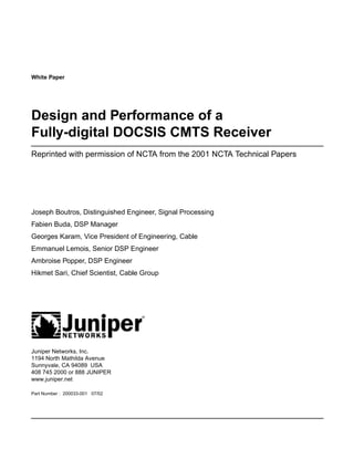
Ingress Noise Canceller Performance
Performance of the implemented ingress noise canceller was simulated using a 16-QAM signal
at the symbol rate of 2.56 Mbaud. The ingress noise model used includes three interferers
respectively centered at a distance of 60 kHz, 500 kHz, and 1,000 kHz from the carrier
frequency. Each interferer has a width of 20 kHz and an individual power that is 15 dB below
the useful signal power.
The results obtained using this model are depicted in Figure 10. Notice that a 16-QAM modem
cannot operate in the presence of this type of ingress noise without an interference canceller.
Clearly, the BER curve shows a floor close to 10-1, which is entirely unacceptable. With a simple
canceller based on noise prediction, the BER curve becomes parallel to the ideal 16-QAM
curve, and the SNR degradation becomes less than 2 dB. Better performance can be achieved
by increasing the number of taps of the noise prediction filter.
Figure 10: Influence of Ingress Noise on 16 QAM and Its Compensation Using Noise Prediction
1E+00
1E- 01
1E- 02
1E- 03
BER
1E- 04
Without Canceler
1E- 05 With Canceler
Theoretical 16-QAM Curve
1E-06
0 2 4 6 8 10 12 14 16 18
Eb/No (dB)
Copyright © 2002, NCTA and Juniper Networks, Inc. 16
17. Design and Performance of a Fully-Digital DOCSIS CMTS Receiver
Conclusion
We have presented a fully digital receiver architecture that substantially reduces the size and
cost of the CMTS while ensuring excellent overall performance even under worst-case
conditions. First, the simulation and measurement results confirmed that the multi-channel
front-end gives quasi-ideal performance in the very unfavorable condition where in addition
to the useful signal, the cable carries a multiplex of 8 modulated carriers with an individual
power that is 24 dB above that of the useful signal. Next, the total SNR degradation of the
receiver at the (uncoded) BER of 10-6 was found to be limited to 0.2 dB in the QPSK mode and
0.6 dB in the 16-QAM mode. It was also found that with the synchronization algorithms
implemented, the average time needed by a cable modem to register with the network
(assuming only one cable modem is trying at a time) is only 1.01 times the ranging opportunity,
which is an extremely short registration time. Finally, the receiver also includes an efficient
adaptive equalizer to compensate for channel distortion and an ingress noise canceller.
The presented receiver was extensively tested using an FPGA implementation and integrated
in an ASIC using high-speed 0.18µ CMOS technology.
Acronyms
ADSL asymmetric digital subscriber loops
BER bit error rate
CMOS complimentary metal oxide silicon
CMTS cable modem termination system
DAVIC Digital Audio-Visual Council
DLC data link control
DOCSIS Data over Cable System Interface Specifications
DVB Digital Video Broadcasting
EuroDOCSIS European Data over Cable System Interface Specifications
FDMA frequency-division multiple access
FEC forward error correction
FPGA field programmable gate array
GF Galois field
HFC hybrid fiber coax
IEEE Institute of Electrical and Electronics Engineers
ISI intersymbol interference
MAC medium access control
MCNS Multimedia Cable Network Systems
Copyright © 2002, NCTA and Juniper Networks, Inc. 17
18. Design and Performance of a Fully-Digital DOCSIS CMTS Receiver
MMSE minimum mean-square error
NCO numerically controlled oscillator
PHY physical
psd power spectral density
QAM quadrature amplitude modulation
QPSK quaternary phase shift keying
RF radio frequency
RS Reed Solomon
SNR signal-to-noise ratio
TDMA time-division multiple access
References
[1} Data-over-Cable Service Interface Specifications – Radio Frequency Interface Specification,
SP-RFI-105-991105, Cable Television Laboratories, November 1999, Louisville, Colorado.
[2} Digital Multiprogram Systems for Television Sound and Data Services for Cable
Distribution, ITU-T Recommendation J.83 (Annex B), April 1997, ITU, Geneva, Switzerland.
[3] Proakis, “Digital Communications”, Third Edition, McGraw Hill, 1995.
[4] R. Blahut, “Error Control Codes,” Addison Wesley, Reading, MA, 1984.
[5] G. C. Clark, Jr., and J. B. Cain, “Error Correction Coding for Digital Communications,”
Plenum Press, New York, 1981.
[6] J. K. Wolf and E. Zehavi, “Pragmatic Trellis Codes Utilizing Punctured Convolutional
Codes”, IEEE Communications Magazine, no. 32, pages 94 – 99, February 1995.
Copyright © 2002, Juniper Networks, Inc. All rights reserved. Juniper Networks is registered in the U.S. Patent and Trademark Office and in
other countries as a trademark of Juniper Networks, Inc. Broadband Cable Processor, ERX, ESP, G10, Internet Processor, JUNOS, JUNOScript,
M5, M10, M20, M40, M40e, M160, MRX, M-series, SDX, ServiceGuard, T640, T-series, UMC, and Unison are trademarks of Juniper Networks,
Inc. All other trademarks, service marks, registered trademarks, or registered service marks are the property of their respective owners. All
specifications are subject to change without notice.
Juniper Networks assumes no responsibility for any inaccuracies in this document. Juniper Networks reserves the right to change, modify,
transfer, or otherwise revise this publication without notice.
Copyright © 2002, NCTA and Juniper Networks, Inc. 18