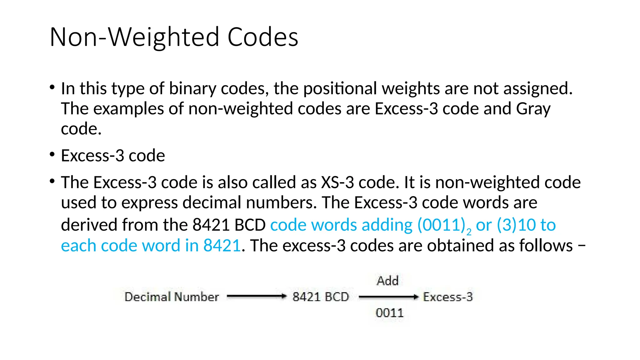
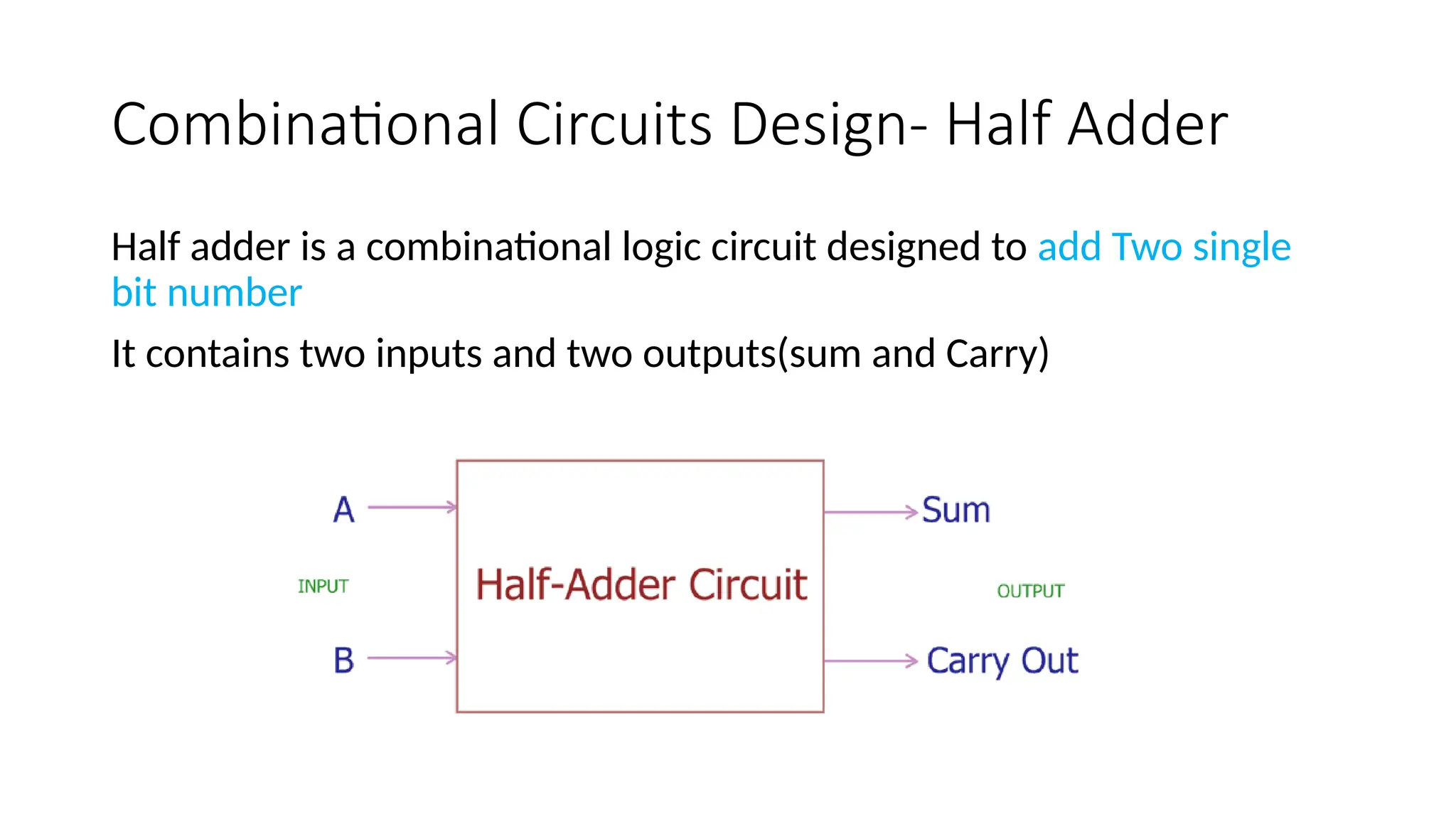
Codes and Arithmetic
operation
Module-3
DIGITAL CODES:-
• In practice the digital electronics requires to handle data which may
be numeric, alphabets and special characters. This requires the
conversion of the incoming data into binary format before it can be
processed. There is various possible ways of doing this and this
process is called encoding. To achieve the reverse of it, we use
decoders.
WEIGHTED AND NON-WEIGHTED CODES
• There are two types of binary codes
1) Weighted binary codes
2) Non- weighted binary codes
• In weighted codes, for each position ( or bit) ,there is specific weight attached.
• For example, in binary number, each bit is assigned particular weight 2n
where
‘n’ is the bit number for n = 0,1,2,3,4 the weights are 1,2,4,8,16 respectively.
Example :- BCD
• Non-weighted codes are codes which are not assigned with any weight to each
digit position, i.e., each digit position within the number is not assigned fixed
value.
Example:- Excess – 3 (XS -3) code and Gray codes
BINARY CODED DECIMAL (BCD)
BCD is a weighted code. In weighted codes, each successive digit from right to
left represents weights equal to some specified value and to get the equivalent
decimal number add the products of the weights by the corresponding binary
digit. 8421 is the most common because 8421 BCD is the most natural amongst
the other possible codes.
Decimal to Binary Conversion
BCD ADDITION
Addition of BCD (8421) is performed by adding two digits of binary, starting
from least significant digit. In case if the result is an illegal code (greater than 9)
or if there is a carry out of one then add 0110(6) and add the resulting carry to
the next most significant.
Perform BCD Addition of 6 and 7
When we add 6 and 7 in BCD,
we get 1101 which is an
invalid state therefore, we
add 0110 (6) to the sum to
get correct result which
is 0001 0011 (13).
The BCD system consists of 4 bits, so
the total number of values it can have
is 2^4=16. But since the numbers from
10 to 15 of the total possible 16 are
considered invalid, if you add 6, the
invalid states are skipped and the code
returns to valid BCD code again.
Perform BCD Addition of 8765 and 3943
BCD representation of 8765 is given as 1000 0111 0110 0011 and for 3943 it is 0011 1001 0100 0011
Perform a normal binary addition of two numbers. Now we see 1100 and 1010 which are illegal states also the
third group of 4-bits from LSB side i.e., 0000 has a carry 1 to the next group. So, for correction, we have to
add 0110 to all three groups. Thus, we get the correct result as 0001 0010 0111 0000 1000 which is equivalent
to (12708)10 in decimal number system and this is what we get on adding (8765)10 + (3943)10 = (12708)10
For 984 and 599, Find BCD Addition
The BCD subtraction is performed by subtracting the digits of each 4 – bit
group of the subtrahend from corresponding 4 – bit group of the minuend in
the binary starting from the LSD. If there is no borrow from the next higher
group[ then no correction is required. If there is a borrow from the next group,
then 6 (0110) is subtracted from the difference term of this group.
BCD SUBTRACTION
• Subtract 201 from 273 = 0000 0111 0010 = (72)10
• Subtract 567.3 from 576.1 = 0000 0000 1000.1000 = (8.8)10
Non-Weighted Codes
• In this type of binary codes, the positional weights are not assigned.
The examples of non-weighted codes are Excess-3 code and Gray
code.
• Excess-3 code
• The Excess-3 code is also called as XS-3 code. It is non-weighted code
used to express decimal numbers. The Excess-3 code words are
derived from the 8421 BCD code words adding (0011)2 or (3)10 to
each code word in 8421. The excess-3 codes are obtained as follows −
EXCESS THREE(XS-3) CODE
The Excess-3 code, also called XS-3, is a non- weighted BCD code. This
derives it name from the fact that each binary code word is the
corresponding 8421 code word plus 0011(3). It is a sequential code. It is
a self complementing code.
XS-3 ADDITION
In XS-3 addition, add the XS-3 numbers by adding the 4 bit groups in each
column starting from the LSD. If there is no carry out from the addition of any
of the 4 bit groups, subtract 0011 from the sum term of those groups. If there is
a carry out, add 0011 to the sum term of those groups
For 983 and 187, Find Excess 3 Addition method
XS-3 SUBTRACTION
To subtract in XS-3 number by subtracting each 4-bit group of the subtrahend
from the corresponding 4-bit group of the minuend starting from the LSD. If
there is no borrow from the next 4-bit group. add 0011 to the difference term of
such groups. If there is a borrow, subtract 0011 from the difference term.
ASCII CODE
The American Standard Code for Information Interchange (ASCII)
pronounced as ‘ASKEE’ is widely used alphanumeric code. This is
basically a 7 bit code. The number of different bit patterns that can be
created with 7 bits is 128 , the ASCII can be used to encode both the
uppercase and lowercase characters of the alphabet (52 symbols) and
some special symbols in addition to the 10 decimal digits. It is used
extensively for printers and terminals that interface with small
computer systems. The table shown below shows the ASCII groups.
There are 128 standard ASCII codes, each of which can be represented
by a 7-digit binary number: 0000000 through 1111111.
EBCDIC CODE
The Extended Binary Coded Decimal Interchange Code (EBCDIC)
pronounced as ‘eb – si- dik’ is an 8 bit alphanumeric code. Since 2^8 =
256 bit patterns can be formed with 8 bits. It is used by most large
computers to communicate in alphanumeric data. The table shown
below shows the EBCDIC code.
GRAY CODE
The gray code is a non-weighted code. It is not a BCD code. It is cyclic
code because successive words in this differ in one bit position only i.e
it is a unit distance code. Gray code is used in instrumentation and data
acquisition systems where linear or angular displacement is measured.
They are also used in shaft encoders, I/O devices, A/D converters and
other peripheral equipment.
Binary to Gray code conversion
For example take the binary value b3, b2, b1, b0 = 1101 and find the gray code
g3, g2, g1, g0 based on the above concept.
g3=b3=1
g2 = b3 XOR b2 = 1 XOR 1 =0
g1= b2 XOR b1= 1 XOR 0 = 1
g0= b1 XOR b0= 0 XOR 1 = 1
The final gray code for the value of binary 1101 is 1011
Binary to Gray code conversion
1) b3, b2, b1, b0 = 1001
2) b3, b2, b1, b0 = 0011
3) b3, b2, b1, b0 = 1010
4) b3, b2, b1, b0 =1110
5) b3, b2, b1, b0 =0101
Gray code to Binary conversion
For example take the gray value g3, g2, g1, g0 = 0011 and find the binary
code b3, b2, b1, b0.
b3=g3=0
b2 = b3 XOR g2 = 0 XOR 0 =0
b1= b2 XOR g1= 0 XOR 1 = 1
b0= b1 XOR g0= 1 XOR 1 = 0
The final binary code for the value of gray 0011 is 0010
Convert Gray code 100111 into Binary number
b5=g5=1=1
b4=g5 g
⊕ 4 =1 0 =1
⊕
b3=b4 g
⊕ 3 =1 0 =1
⊕
b2=b3 g
⊕ 2 =1 1 =0
⊕
b1=b2 g
⊕ 1 =0 1 =1
⊕
b0=b1 g
⊕ 0 =1 1 =0
⊕
So, Binary number will be 111010
Gray code to Binary conversion
1) g3, g2, g1, g0 = 1001
2) g3, g2, g1, g0 = 0011
3) g3, g2, g1, g0 = 1010
4) g3, g2, g1, g0 =1110
5) g3, g2, g1, g0 =0101
Combinational Circuits Design- Half Adder
Half adder is a combinational logic circuit designed to add Two single
bit number
It contains two inputs and two outputs(sum and Carry)
Limitation of Half Adder
• Half adders have no scope of adding the carry bit resulting from the
addition of previous bits.
• This is a major drawback of half adders.
• This is because real time scenarios involve adding the multiple
number of bits which can not be accomplished using half adders.
• To overcome this drawback, Full Adder comes into play.
Full Adder
• Full Adder is a combinational logic circuit.
• It is used for the purpose of adding two single bit numbers with a
carry.
• Thus, full adder has the ability to perform the addition of three bits.
• Full adder contains 3 inputs and 2 outputs (sum and carry) as shown
Implement 8*1 multiplexer using 4*1 and 2*1 multiplexers
Implement 16*1 multiplexer using 8*1 and 2*1 multiplexers
From the Truth table, we can
directly write the Boolean
functions for each output as –
Y3=s1s0I
Y2=s1s0′I
Y1=s1′s0I
Y0=s1′s0′I
Multiplexer Demultiplexer
Multiplexer processes the digital
information from various sources into a
single source.
Demultiplexer receives digital information
from a single source and converts it into
several sources
It is known as Data Selector It is known as Data Distributor
Multiplexer is a digital switch Demultiplexer is a digital circuit
It follows combinational logic type It also follows combinational logic type
It has n data input It has single data input
It has a single data output It has n data outputs
It works on many to one operational
principle
It works on one to many operational
principle
In time division Multiplexing, multiplexer
is used at the transmitter end
In time division Multiplexing,
demultiplexer is used at the receiver end
Y3=E.A1.A0
Y2=E.A1.A0′
Y1=E.A1′.A0
Y0=E.A1′.A0′
Each output is having one product term. So, there are four product
terms in total. We can implement these four product terms by using
four AND gates having three inputs each & two inverters. The circuit
diagram of 2 to 4 decoder is shown in the following figure.
Therefore, the outputs of 2 to 4 decoder are nothing but the min
terms of two input variables A1 & A0, when enable, E is equal to one. If
enable, E is zero, then all the outputs of decoder will be equal to zero.
Similarly, 3 to 8 decoder produces eight min terms of three input
variables A2, A1 & A0 and 4 to 16 decoder produces sixteen min terms
of four input variables A3, A2, A1 & A0.
Sequential Circuits
Combinational Circuits Sequential Circuits
Outputs depend only on present inputs. Outputs depend on both present inputs
and present state.
Feedback path is not present. Feedback path is present.
Memory elements are not required. Memory elements are required.
Clock signal is not required. Clock signal is required.
Easy to design. Difficult to design.
Differences between combinational circuits and sequential
circuits -
Types of Sequential Circuits –
•Asynchronous sequential circuits
•Synchronous sequential circuits
Module_3_Codes and Arithmetic operation.pptx

Module_3_Codes and Arithmetic operation.pptx

  • 1.
  • 2.
    DIGITAL CODES:- • Inpractice the digital electronics requires to handle data which may be numeric, alphabets and special characters. This requires the conversion of the incoming data into binary format before it can be processed. There is various possible ways of doing this and this process is called encoding. To achieve the reverse of it, we use decoders.
  • 3.
    WEIGHTED AND NON-WEIGHTEDCODES • There are two types of binary codes 1) Weighted binary codes 2) Non- weighted binary codes • In weighted codes, for each position ( or bit) ,there is specific weight attached. • For example, in binary number, each bit is assigned particular weight 2n where ‘n’ is the bit number for n = 0,1,2,3,4 the weights are 1,2,4,8,16 respectively. Example :- BCD • Non-weighted codes are codes which are not assigned with any weight to each digit position, i.e., each digit position within the number is not assigned fixed value. Example:- Excess – 3 (XS -3) code and Gray codes
  • 4.
    BINARY CODED DECIMAL(BCD) BCD is a weighted code. In weighted codes, each successive digit from right to left represents weights equal to some specified value and to get the equivalent decimal number add the products of the weights by the corresponding binary digit. 8421 is the most common because 8421 BCD is the most natural amongst the other possible codes.
  • 5.
  • 6.
    BCD ADDITION Addition ofBCD (8421) is performed by adding two digits of binary, starting from least significant digit. In case if the result is an illegal code (greater than 9) or if there is a carry out of one then add 0110(6) and add the resulting carry to the next most significant.
  • 7.
    Perform BCD Additionof 6 and 7 When we add 6 and 7 in BCD, we get 1101 which is an invalid state therefore, we add 0110 (6) to the sum to get correct result which is 0001 0011 (13). The BCD system consists of 4 bits, so the total number of values it can have is 2^4=16. But since the numbers from 10 to 15 of the total possible 16 are considered invalid, if you add 6, the invalid states are skipped and the code returns to valid BCD code again.
  • 8.
    Perform BCD Additionof 8765 and 3943 BCD representation of 8765 is given as 1000 0111 0110 0011 and for 3943 it is 0011 1001 0100 0011 Perform a normal binary addition of two numbers. Now we see 1100 and 1010 which are illegal states also the third group of 4-bits from LSB side i.e., 0000 has a carry 1 to the next group. So, for correction, we have to add 0110 to all three groups. Thus, we get the correct result as 0001 0010 0111 0000 1000 which is equivalent to (12708)10 in decimal number system and this is what we get on adding (8765)10 + (3943)10 = (12708)10
  • 9.
    For 984 and599, Find BCD Addition
  • 10.
    The BCD subtractionis performed by subtracting the digits of each 4 – bit group of the subtrahend from corresponding 4 – bit group of the minuend in the binary starting from the LSD. If there is no borrow from the next higher group[ then no correction is required. If there is a borrow from the next group, then 6 (0110) is subtracted from the difference term of this group. BCD SUBTRACTION
  • 11.
    • Subtract 201from 273 = 0000 0111 0010 = (72)10 • Subtract 567.3 from 576.1 = 0000 0000 1000.1000 = (8.8)10
  • 12.
    Non-Weighted Codes • Inthis type of binary codes, the positional weights are not assigned. The examples of non-weighted codes are Excess-3 code and Gray code. • Excess-3 code • The Excess-3 code is also called as XS-3 code. It is non-weighted code used to express decimal numbers. The Excess-3 code words are derived from the 8421 BCD code words adding (0011)2 or (3)10 to each code word in 8421. The excess-3 codes are obtained as follows −
  • 13.
    EXCESS THREE(XS-3) CODE TheExcess-3 code, also called XS-3, is a non- weighted BCD code. This derives it name from the fact that each binary code word is the corresponding 8421 code word plus 0011(3). It is a sequential code. It is a self complementing code.
  • 15.
    XS-3 ADDITION In XS-3addition, add the XS-3 numbers by adding the 4 bit groups in each column starting from the LSD. If there is no carry out from the addition of any of the 4 bit groups, subtract 0011 from the sum term of those groups. If there is a carry out, add 0011 to the sum term of those groups
  • 16.
    For 983 and187, Find Excess 3 Addition method
  • 20.
    XS-3 SUBTRACTION To subtractin XS-3 number by subtracting each 4-bit group of the subtrahend from the corresponding 4-bit group of the minuend starting from the LSD. If there is no borrow from the next 4-bit group. add 0011 to the difference term of such groups. If there is a borrow, subtract 0011 from the difference term.
  • 22.
    ASCII CODE The AmericanStandard Code for Information Interchange (ASCII) pronounced as ‘ASKEE’ is widely used alphanumeric code. This is basically a 7 bit code. The number of different bit patterns that can be created with 7 bits is 128 , the ASCII can be used to encode both the uppercase and lowercase characters of the alphabet (52 symbols) and some special symbols in addition to the 10 decimal digits. It is used extensively for printers and terminals that interface with small computer systems. The table shown below shows the ASCII groups. There are 128 standard ASCII codes, each of which can be represented by a 7-digit binary number: 0000000 through 1111111.
  • 24.
    EBCDIC CODE The ExtendedBinary Coded Decimal Interchange Code (EBCDIC) pronounced as ‘eb – si- dik’ is an 8 bit alphanumeric code. Since 2^8 = 256 bit patterns can be formed with 8 bits. It is used by most large computers to communicate in alphanumeric data. The table shown below shows the EBCDIC code.
  • 26.
    GRAY CODE The graycode is a non-weighted code. It is not a BCD code. It is cyclic code because successive words in this differ in one bit position only i.e it is a unit distance code. Gray code is used in instrumentation and data acquisition systems where linear or angular displacement is measured. They are also used in shaft encoders, I/O devices, A/D converters and other peripheral equipment.
  • 27.
    Binary to Graycode conversion For example take the binary value b3, b2, b1, b0 = 1101 and find the gray code g3, g2, g1, g0 based on the above concept. g3=b3=1 g2 = b3 XOR b2 = 1 XOR 1 =0 g1= b2 XOR b1= 1 XOR 0 = 1 g0= b1 XOR b0= 0 XOR 1 = 1 The final gray code for the value of binary 1101 is 1011
  • 28.
    Binary to Graycode conversion 1) b3, b2, b1, b0 = 1001 2) b3, b2, b1, b0 = 0011 3) b3, b2, b1, b0 = 1010 4) b3, b2, b1, b0 =1110 5) b3, b2, b1, b0 =0101
  • 29.
    Gray code toBinary conversion For example take the gray value g3, g2, g1, g0 = 0011 and find the binary code b3, b2, b1, b0. b3=g3=0 b2 = b3 XOR g2 = 0 XOR 0 =0 b1= b2 XOR g1= 0 XOR 1 = 1 b0= b1 XOR g0= 1 XOR 1 = 0 The final binary code for the value of gray 0011 is 0010
  • 30.
    Convert Gray code100111 into Binary number b5=g5=1=1 b4=g5 g ⊕ 4 =1 0 =1 ⊕ b3=b4 g ⊕ 3 =1 0 =1 ⊕ b2=b3 g ⊕ 2 =1 1 =0 ⊕ b1=b2 g ⊕ 1 =0 1 =1 ⊕ b0=b1 g ⊕ 0 =1 1 =0 ⊕ So, Binary number will be 111010
  • 31.
    Gray code toBinary conversion 1) g3, g2, g1, g0 = 1001 2) g3, g2, g1, g0 = 0011 3) g3, g2, g1, g0 = 1010 4) g3, g2, g1, g0 =1110 5) g3, g2, g1, g0 =0101
  • 37.
    Combinational Circuits Design-Half Adder Half adder is a combinational logic circuit designed to add Two single bit number It contains two inputs and two outputs(sum and Carry)
  • 40.
    Limitation of HalfAdder • Half adders have no scope of adding the carry bit resulting from the addition of previous bits. • This is a major drawback of half adders. • This is because real time scenarios involve adding the multiple number of bits which can not be accomplished using half adders. • To overcome this drawback, Full Adder comes into play.
  • 41.
    Full Adder • FullAdder is a combinational logic circuit. • It is used for the purpose of adding two single bit numbers with a carry. • Thus, full adder has the ability to perform the addition of three bits. • Full adder contains 3 inputs and 2 outputs (sum and carry) as shown
  • 58.
    Implement 8*1 multiplexerusing 4*1 and 2*1 multiplexers
  • 59.
    Implement 16*1 multiplexerusing 8*1 and 2*1 multiplexers
  • 61.
    From the Truthtable, we can directly write the Boolean functions for each output as – Y3=s1s0I Y2=s1s0′I Y1=s1′s0I Y0=s1′s0′I
  • 65.
    Multiplexer Demultiplexer Multiplexer processesthe digital information from various sources into a single source. Demultiplexer receives digital information from a single source and converts it into several sources It is known as Data Selector It is known as Data Distributor Multiplexer is a digital switch Demultiplexer is a digital circuit It follows combinational logic type It also follows combinational logic type It has n data input It has single data input It has a single data output It has n data outputs It works on many to one operational principle It works on one to many operational principle In time division Multiplexing, multiplexer is used at the transmitter end In time division Multiplexing, demultiplexer is used at the receiver end
  • 67.
    Y3=E.A1.A0 Y2=E.A1.A0′ Y1=E.A1′.A0 Y0=E.A1′.A0′ Each output ishaving one product term. So, there are four product terms in total. We can implement these four product terms by using four AND gates having three inputs each & two inverters. The circuit diagram of 2 to 4 decoder is shown in the following figure. Therefore, the outputs of 2 to 4 decoder are nothing but the min terms of two input variables A1 & A0, when enable, E is equal to one. If enable, E is zero, then all the outputs of decoder will be equal to zero. Similarly, 3 to 8 decoder produces eight min terms of three input variables A2, A1 & A0 and 4 to 16 decoder produces sixteen min terms of four input variables A3, A2, A1 & A0.
  • 70.
  • 71.
    Combinational Circuits SequentialCircuits Outputs depend only on present inputs. Outputs depend on both present inputs and present state. Feedback path is not present. Feedback path is present. Memory elements are not required. Memory elements are required. Clock signal is not required. Clock signal is required. Easy to design. Difficult to design. Differences between combinational circuits and sequential circuits - Types of Sequential Circuits – •Asynchronous sequential circuits •Synchronous sequential circuits