Fundamentals of Roboticsand Applications
(Course Code: BRA301)
DEPARTMENT OF ROBOTICS & AUTOMATION
Dr. RAJAKUMAR D G
Professor & Head
Department of Robotics & Automation
GMIT, Davangere-577006
rajakumardg@gmit.ac.in
2.
Books
• S.R. Deb,Robotics Technology and flexible automation, Tata McGraw-Hill Education, 2009.
• Mikell P. Groover et al., "Industrial Robots - Technology, Programming and Applications", McGraw
Hill, Special Edition, (2012).
• Ganesh S Hegde, “A textbook on Industrial Robotics”, University Science Press, 3rd edition,
2017.
Reference
• Richard D Klafter, Thomas A Chmielewski, Michael Negin, "Robotics Engineering – An Integrated
Approach", Eastern Economy Edition, Prentice Hall of India Pvt. Ltd., 2006.
• Fu K S, Gonzalez R C, Lee C.S.G, "Robotics: Control, Sensing, Vision and Intelligence", McGraw
Hill, 1987.
Further Learning
https://www.robots.com/applications
Dr. Rajakumar D G, GMIT, Davangere 1
3.
Course Learning Objectives(CLO)
• Understand the fundamental/elementary concepts of Robotics.
• Provide insight into different types of robots.
• Explain the intelligent module for robotic motion control.
• Educate on various path-planning techniques.
• Illustrate the working of innovative robotic devices.
Dr. Rajakumar D G, GMIT, Davangere 2
4.
Course outcomes (COs)(Course Skill Set)
CO1: Understand the significance, social impact and future prospects of robotics and
automation in various engineering applications
CO2: Identify and describe the components and anatomy of the robotic system.
CO3: Know about various path planning techniques and analyze different motions of the
robotics system
CO4: Use the suitable drives and end-effectors for a given robotics application.
CO5: Apply the robotics concept to automate monotonous and hazardous tasks and
Categorise various types of robots based on their design and applications.
At the end of the course, students will be able to,
Dr. Rajakumar D G, GMIT, Davangere 3
5.
Continuous Internal Evaluation(CIE)
• Assignment Component = 25 Marks
• Internal Assessment (IA) component = 25 Marks
• Two IA Tests, each of 25 Marks
• Two assignments each of 25 Marks
• For the course, CIE marks will be based on a scaled-down sum of two tests and other
assessment methods.
The minimum passing mark for the CIE is 40% of the maximum marks (20 marks out of 50)
Dr. Rajakumar D G, GMIT, Davangere 4
6.
Semester End Examination(SEE)
•The question paper shall be set for 100 marks.
• The duration of SEE is 03 hours.
• The question paper will have 10 questions.
• 2 questions per module. Each question is set for 20 marks.
• The students have to answer 5 full questions, selecting one full question from each module.
• The student has to answer for 100 marks and marks scored out of 100 shall be
proportionally reduced to 50 marks.
• SEE minimum passing mark is 35% of the maximum marks (18 out of 50 marks).
• Students should secure a minimum of 40% (40 marks out of 100) in the sum total of the CIE and SEE
taken together.
Dr. Rajakumar D G, GMIT, Davangere 5
7.
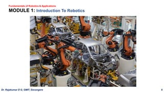
Fundamentals of Robotics& Applications
MODULE 1: Introduction To Robotics
Dr. Rajakumar D G, GMIT, Davangere 6
8.
MODULE 1: IntroductionTo Robotics
• Introduction To Robotics: Introduction to Robotics and Automation
• Laws of robots.
• Brief history of robotics, basic components of the robot, and robot specifications.
• Classification of robots, human systems and robotics.
• Safety measures in robotics, social impact.
• Robotics market and the future prospects.
• Advantages and disadvantages of robots.
Content
Dr. Rajakumar D G, GMIT, Davangere 7
9.
Introduction
Difference between Roboticsand Automation
• Robotics is the design, creation, and use of robots to perform tasks. These are physical robots
that substitute for (or replicate) human actions.
• Automation as a technology concerned with the use of Mechanical, Electronic and Computer-
based systems in the operation and control of Production.
• E.g. : Transfer lines, mechanised assembly machines, feedback control systems, NC Machine
tools and robots
• Robotics is a field that combines engineering and computer science to design and build robots to perform
tasks.
Dr. Rajakumar D G, GMIT, Davangere 8
10.
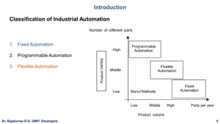
Introduction
1. Fixed Automation
2.Programmable Automation
3. Flexible Automation
Classification of Industrial Automation
Dr. Rajakumar D G, GMIT, Davangere 9
11.
Introduction
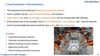
• The sequenceof processing is fixed for one particular product.
• Such a system can be used for mass production of a product.
• Initial cost is high, and any changes in product design can be incorporated with difficulty.
• If the product has to be changed, then a lot of modifications, new additions, etc., may be required,
and to accommodate the same would be very costly and time-consuming.
1. Fixed Automation / Hard Automation
Examples
• Automated assembly machines
• Chemical manufacturing processes
• Material handling conveyor systems
• Machining transfer lines
• Paint & coating automation processes
Dr. Rajakumar D G, GMIT, Davangere 10
12.
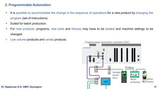
• It ispossible to accommodate the change in the sequence of operations for a new product by changing the
program (set of instructions).
• Suited for batch production.
• For new products, programs, new tools and fixtures may have to be loaded and machine settings to be
changed.
• Low volume products and variety products
2. Programmable Automation
Dr. Rajakumar D G, GMIT, Davangere 11
13.
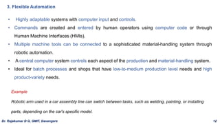
• Highly adaptablesystems with computer input and controls.
• Commands are created and entered by human operators using computer code or through
Human Machine Interfaces (HMIs).
• Multiple machine tools can be connected to a sophisticated material-handling system through
robotic automation.
• A central computer system controls each aspect of the production and material-handling system.
• Ideal for batch processes and shops that have low-to-medium production level needs and high
product-variety needs.
3. Flexible Automation
Example
Robotic arm used in a car assembly line can switch between tasks, such as welding, painting, or installing
parts, depending on the car's specific model.
Dr. Rajakumar D G, GMIT, Davangere 12
14.
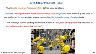
• The RoboticIndustries Association (RIA) defines robot as follows:
"A robot is a reprogrammable, multifunctional manipulator designed to move material, parts, tools or
special devices through variable programmed motions for the performance of various tasks."
• The industry’s current working definition of a robot is “any piece of equipment that has three or
more degrees of movement or freedom”.
Definition of Industrial Robot
Dr. Rajakumar D G, GMIT, Davangere 13
15.
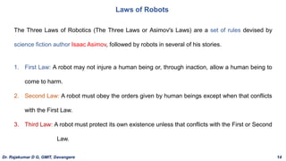
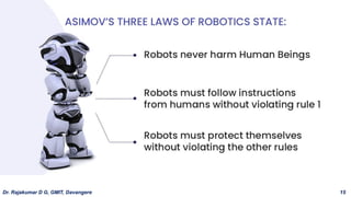
Laws of Robots
TheThree Laws of Robotics (The Three Laws or Asimov's Laws) are a set of rules devised by
science fiction author Isaac Asimov, followed by robots in several of his stories.
1. First Law: A robot may not injure a human being or, through inaction, allow a human being to
come to harm.
2. Second Law: A robot must obey the orders given by human beings except when that conflicts
with the First Law.
3. Third Law: A robot must protect its own existence unless that conflicts with the First or Second
Law.
Dr. Rajakumar D G, GMIT, Davangere 14
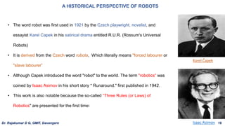
• The wordrobot was first used in 1921 by the Czech playwright, novelist, and
essayist Karel Capek in his satirical drama entitled R.U.R. (Rossum's Universal
Robots)
• It is derived from the Czech word robota, Which literally means "forced labourer or
"slave labourer”
• Although Capek introduced the word "robot" to the world. The term "robotics“ was
coined by Isaac Asimov in his short story * Runaround." first published in 1942.
• This work is also notable because the so-called “Three Rules (or Laws) of
Robotics" are presented for the first time:
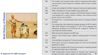
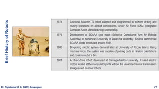
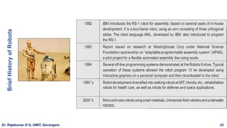
A HISTORICAL PERSPECTIVE OF ROBOTS
Isaac Asimov
Karel Čapek
Dr. Rajakumar D G, GMIT, Davangere 16
18.
A HISTORICAL PERSPECTIVEOF ROBOTS
GENERATIONS OF ROBOT
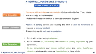
First Generation
• Non-servo, pick-and-place or point-to-point robots are classified as 1st gen. robots.
• The technology is fully developed.
• Predicted that these will continue to be in use for another 20 years.
Second Generation
• Addition of sensing devices and enabling the robot to alter its movements in
response to sensory feedback
• These robots exhibit path control capabilities
Third Generation
• Robots with a brain having intelligence.
• Robots acquired AI, self-learning and conclusion drawing capabilities by past
experiences.
• On-line computations and control, artificial vision and active force/torque
interaction with the environment are characteristics of these robots.
Dr. Rajakumar D G, GMIT, Davangere 17
19.
A HISTORICAL PERSPECTIVEOF ROBOTS
GENERATIONS OF ROBOT
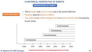
Fourth Generation
• This is futuristic and may be a reality only in the current millennium
• Prediction about its features is difficult
• True android or an artificial biological robot or a super humanoid robot of producing
its own clones.
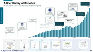
A pictorial representation of overlapping generations of robots
Dr. Rajakumar D G, GMIT, Davangere 18
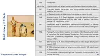
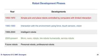
Robot Development Phases
YearDevelopments
1950-1970 Simple pick and place robots controlled by computers with limited interaction
1980-1990 Interaction with the environment using force, touch sensors, vision
1999-2000 Intelligent robots
2000-present Micro, nano, robots, bio-robots humanoids, service robots
Future robots Personal robots, professional robots
Dr. Rajakumar D G, GMIT, Davangere 24
26.
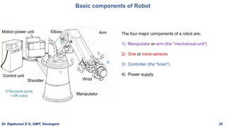
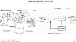
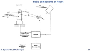
Basic components ofRobot
The four major components of a robot are;
1) Manipulator or arm (the "mechanical unit")
2) One or more sensors
3) Controller (the "brain")
4) Power supply
Dr. Rajakumar D G, GMIT, Davangere 25
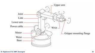
Basic components ofRobot
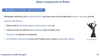
1. Manipulator or arm (the "mechanical unit")
Manipulator defined by the joint-link structure, has three main structural elements: the arm, the wrist, and the
hand (or end effector).
• Robot need to manipulate objects: pickup, place, hold, etc.
• Hands of robot are referred as end effectors (end of robotic arm)
• Robot Arm is referred as manipulator
• End effectors are the tools at the end of robotic arms, directly interact with objects.
Dr. Rajakumar D G, GMIT, Davangere 29
31.
Basic components ofRobot
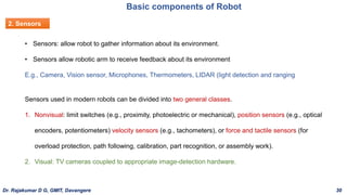
2. Sensors
• Sensors: allow robot to gather information about its environment.
• Sensors allow robotic arm to receive feedback about its environment
E.g., Camera, Vision sensor, Microphones, Thermometers, LIDAR (light detection and ranging
Sensors used in modern robots can be divided into two general classes.
1. Nonvisual: limit switches (e.g., proximity, photoelectric or mechanical), position sensors (e.g., optical
encoders, potentiometers) velocity sensors (e.g., tachometers), or force and tactile sensors (for
overload protection, path following, calibration, part recognition, or assembly work).
2. Visual: TV cameras coupled to appropriate image-detection hardware.
Dr. Rajakumar D G, GMIT, Davangere 30
32.
Basic components ofRobot
3. Controller
1. They initiate and terminate the motion of the individual components of the manipulator in a desired
sequence and at specified points.
2. They store position and sequence data in their memory.
3. They permit the robot to be interfaced to the "outside" world via sensors
Robot controllers generally perform three functions;
• To carry out these tasks, controllers must perform the arithmetic computations for determining the
correct manipulator path, speed, and position.
• They must also send signals to the joint-actuating devices (via interfaces) and utilize the information
provided by the robot's sensors.
• They must permit communication between peripheral devices and the manipulator.
Dr. Rajakumar D G, GMIT, Davangere 31
33.
Basic components ofRobot
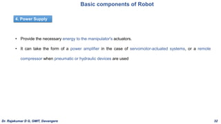
4. Power Supply
• Provide the necessary energy to the manipulator's actuators.
• It can take the form of a power amplifier in the case of servomotor-actuated systems, or a remote
compressor when pneumatic or hydraulic devices are used
Dr. Rajakumar D G, GMIT, Davangere 32
34.
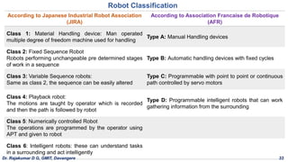
Robot Classification
According toJapanese Industrial Robot Association
(JIRA)
According to Association Francaise de Robotique
(AFR)
Class 1: Material Handling device: Man operated
multiple degree of freedom machine used for handling
Type A: Manual Handling devices
Class 2: Fixed Sequence Robot
Robots performing unchangeable pre determined stages
of work in a sequence
Type B: Automatic handling devices with fixed cycles
Class 3: Variable Sequence robots:
Same as class 2, the sequence can be easily altered
Type C: Programmable with point to point or continuous
path controlled by servo motors
Class 4: Playback robot:
The motions are taught by operator which is recorded
and then the path is followed by robot
Type D: Programmable intelligent robots that can work
gathering information from the surrounding
Class 5: Numerically controlled Robot
The operations are programmed by the operator using
APT and given to robot
Class 6: Intelligent robots: these can understand tasks
in a surrounding and act intelligently
Dr. Rajakumar D G, GMIT, Davangere 33
35.
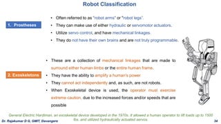
• Often referredto as "robot arms" or "robot legs”.
• They can make use of either hydraulic or servomotor actuators.
• Utilize servo control, and have mechanical linkages.
• They do not have their own brains and are not truly programmable.
Robot Classification
1. Prostheses
2. Exoskeletons
• These are a collection of mechanical linkages that are made to
surround either human limbs or the entire human frame.
• They have the ability to amplify a human's power
• They cannot act independently and, as such, are not robots.
• When Exoskeletal device is used, the operator must exercise
extreme caution, due to the increased forces and/or speeds that are
possible
General Electric Hardiman, an exoskeletal device developed in the 1970s. It allowed a human operator to lift loads up to 1500
lbs. and utilized hydraulically actuated servos.
Dr. Rajakumar D G, GMIT, Davangere 34
36.
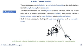
Robot Classification
3. Telecherics
•These devices permit manipulation or movement of materials and/or tools that are
located many feet away from an operator
• Telecheric mechanisms use either hydraulic or servo actuators, which are usually
controlled in a closed-loop manner, they are not robots, because they require a
human being to control and to make decisions about position and speed.
• Such devices are useful in dealing with hazardous substances such as radioactive
waste
G.E. Manmate Industrial Manipulator is an articulating arm boom that can be used for material handing
Dr. Rajakumar D G, GMIT, Davangere 35
37.
Robot Classification
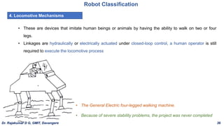
4. LocomotiveMechanisms
• These are devices that imitate human beings or animals by having the ability to walk on two or four
legs.
• Linkages are hydraulically or electrically actuated under closed-loop control, a human operator is still
required to execute the locomotive process
• The General Electric four-legged walking machine.
• Because of severe stability problems, the project was never completed
Dr. Rajakumar D G, GMIT, Davangere 36
38.
Classification by CoordinateSystem / Physical configuration
Robot Classification
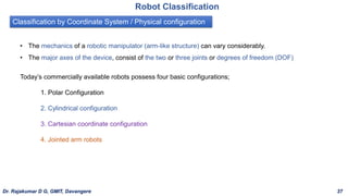
• The mechanics of a robotic manipulator (arm-like structure) can vary considerably.
• The major axes of the device, consist of the two or three joints or degrees of freedom (DOF)
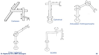
Today’s commercially available robots possess four basic configurations;
1. Polar Configuration
2. Cylindrical configuration
3. Cartesian coordinate configuration
4. Jointed arm robots
Dr. Rajakumar D G, GMIT, Davangere 37
39.
Classification by CoordinateSystem
Robot Classification
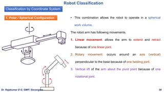
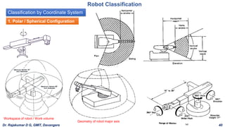
1. Polar / Spherical Configuration • This combination allows the robot to operate in a spherical
work volume.
The robot arm has following movements.
1. Linear movement: allows the arm to extend and retract
because of one linear joint.
2. Rotary movement: occurs around an axis (vertical)
perpendicular to the base because of one twisting joint.
3. Vertical lift of the arm about the pivot point because of one
rotational joint.
Dr. Rajakumar D G, GMIT, Davangere 38
40.
Classification by CoordinateSystem
Robot Classification
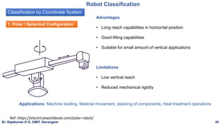
1. Polar / Spherical Configuration
Advantages
• Long reach capabilities in horizontal position
• Good lifting capabilities
• Suitable for small amount of vertical applications
Applications: Machine loading, Material movement, stacking of components, Heat treatment operations
Limitations
• Low vertical reach
• Reduced mechanical rigidity
Ref: https://electricalworkbook.com/polar-robot/
Dr. Rajakumar D G, GMIT, Davangere 39
41.
Classification by CoordinateSystem
Robot Classification
1. Polar / Spherical Configuration
Workspace of robot / Work volume
Geometry of robot major axis
Dr. Rajakumar D G, GMIT, Davangere 40
42.
Classification by CoordinateSystem
Robot Classification
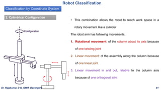
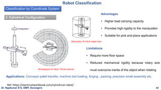
2. Cylindrical Configuration
• This combination allows the robot to reach work space in a
rotary movement like a cylinder
The robot arm has following movements.
1. Rotational movement: of the column about its axis because
of one twisting joint
2. Linear movement: of the assembly along the column because
of one linear joint
3. Linear movement in and out, relative to the column axis
because of one orthogonal joint
Dr. Rajakumar D G, GMIT, Davangere 41
43.
Classification by CoordinateSystem
Robot Classification
Advantages
• Higher load carrying capacity
• Provides high rigidity to the manipulator
• Suitable for pick and place applications
Applications: Conveyor pallet transfer, machine tool loading, forging , packing, precision small assembly etc.
Limitations
• Require more floor space
• Reduced mechanical rigidity because rotary axis
must overcome inertia of the object when rotating
Ref: https://electricalworkbook.com/cylindrical-robot/
2. Cylindrical Configuration
Workspace of robot / Work volume
Geometry of robot major axis
Dr. Rajakumar D G, GMIT, Davangere 42
44.
Classification by CoordinateSystem
Robot Classification
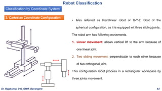
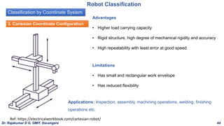
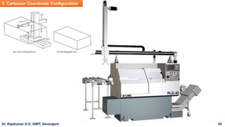
3. Cartesian Coordinate Configuration
• Also referred as Rectilinear robot or X-Y-Z robot of the
spherical configuration, as it is equipped wit three sliding joints.
The robot arm has following movements.
1. Linear movement: allows vertical lift to the arm because of
one linear joint.
2. Two sliding movement: perpendicular to each other because
of two orthogonal joint.
This configuration robot process in a rectangular workspace by
three joints movement.
Dr. Rajakumar D G, GMIT, Davangere 43
45.
Classification by CoordinateSystem
Robot Classification
Advantages
• Higher load carrying capacity
• Rigid structure, high degree of mechanical rigidity and accuracy
• High repeatability with least error at good speed.
Applications: Inspection, assembly, machining operations, welding, finishing
operations etc.
Limitations
• Has small and rectangular work envelope
• Has reduced flexibility
Ref: https://electricalworkbook.com/cartesian-robot/
3. Cartesian Coordinate Configuration
Dr. Rajakumar D G, GMIT, Davangere 44
Classification by CoordinateSystem
Robot Classification
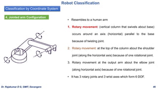
4. Jointed arm Configuration
• Resembles to a human arm
1. Rotary movement: (vertical column that swivels about base)
occurs around an axis (horizontal) parallel to the base
because of twisting joint.
2. Rotary movement: at the top of the column about the shoulder
joint (along the horizontal axis) because of one rotational joint.
3. Rotary movement at the output arm about the elbow joint
(along horizontal axis) because of one rotational joint.
• It has 3 rotary joints and 3 wrist axes which form 6 DOF.
Dr. Rajakumar D G, GMIT, Davangere 46
48.
Classification by CoordinateSystem
Robot Classification
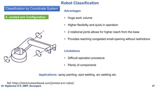
Advantages
• Huge work volume
• Higher flexibility and quick in operation
• 2 rotational joints allows for higher reach from the base
• Provides reaching congested small opening without restrictions
Applications: spray painting, spot welding, arc welding etc.
Limitations
• Difficult operation procedure
• Plenty of components
Ref: https://electricalworkbook.com/jointed-arm-robot/
4. Jointed arm Configuration
Dr. Rajakumar D G, GMIT, Davangere 47
49.
Robot Classification
Ref: https://electricalworkbook.com/jointed-arm-robot/
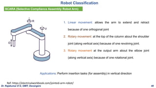
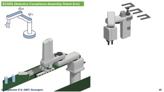
SCARA(Selective Compliance Assembly Robot Arm)
1. Linear movement: allows the arm to extend and retract
because of one orthogonal joint
2. Rotary movement: at the top of the column about the shoulder
joint (along vertical axis) because of one revolving joint.
3. Rotary movement at the output arm about the elbow joint
(along vertical axis) because of one rotational joint.
Applications: Perform insertion tasks (for assembly) in vertical direction
Dr. Rajakumar D G, GMIT, Davangere 48
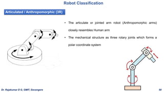
Articulated / Anthropomorphic(3R)
Robot Classification
• The articulate or jointed arm robot (Anthropomorphic arms)
closely resembles Human arm
• The mechanical structure as three rotary joints which forms a
polar coordinate system
Dr. Rajakumar D G, GMIT, Davangere 50
52.
Classification by ControlMethod
Classification based on the technique used to control the various axes of the robot.
1. Non-Servo controlled / limited-sequence robot
2. Servo controlled
3. Point to point servo-controlled robots
4. Continuous path servo-controlled robots
Robot Classification
Dr. Rajakumar D G, GMIT, Davangere 51
53.
Classification by ControlMethod
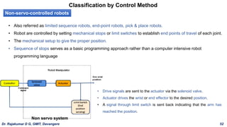
Non-servo-controlled robots
• Also referred as limited sequence robots, end-point robots, pick & place robots.
• Robot are controlled by setting mechanical stops or limit switches to establish end points of travel of each joint.
• The mechanical setup to give the proper position.
• Sequence of stops serves as a basic programming approach rather than a computer intensive robot
programming language
• Drive signals are sent to the actuator via the solenoid valve.
• Actuator drives the wrist or end effector to the desired position.
• A signal through limit switch is sent back indicating that the arm has
reached the position.
Non servo system
Dr. Rajakumar D G, GMIT, Davangere 52
54.
Classification by ControlMethod
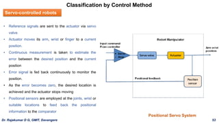
Servo-controlled robots
• Reference signals are sent to the actuator via servo
valve.
• Actuator moves its arm, wrist or finger to a current
position.
• Continuous measurement is taken to estimate the
error between the desired position and the current
position
• Error signal is fed back continuously to monitor the
position.
• As the error becomes zero, the desired location is
achieved and the actuator stops moving
• Positional sensors are employed at the joints, wrist or
suitable locations to feed back the positional
information to the comparator
Positional Servo System
Dr. Rajakumar D G, GMIT, Davangere 53
55.
Classification by ControlMethod
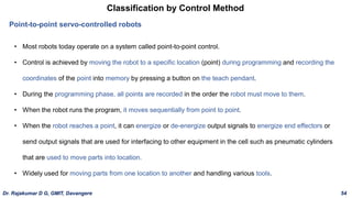
Point-to-point servo-controlled robots
• Most robots today operate on a system called point-to-point control.
• Control is achieved by moving the robot to a specific location (point) during programming and recording the
coordinates of the point into memory by pressing a button on the teach pendant.
• During the programming phase, all points are recorded in the order the robot must move to them.
• When the robot runs the program, it moves sequentially from point to point.
• When the robot reaches a point, it can energize or de-energize output signals to energize end effectors or
send output signals that are used for interfacing to other equipment in the cell such as pneumatic cylinders
that are used to move parts into location.
• Widely used for moving parts from one location to another and handling various tools.
Dr. Rajakumar D G, GMIT, Davangere 54
56.
Classification by ControlMethod
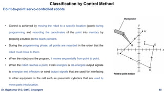
Point-to-point servo-controlled robots
• Control is achieved by moving the robot to a specific location (point) during
programming and recording the coordinates of the point into memory by
pressing a button on the teach pendant.
• During the programming phase, all points are recorded in the order that the
robot must move to them.
• When the robot runs the program, it moves sequentially from point to point.
• When the robot reaches a point, it can energize or de-energize output signals
to energize end effectors or send output signals that are used for interfacing
to other equipment in the cell such as pneumatic cylinders that are used to
move parts into location.
Dr. Rajakumar D G, GMIT, Davangere 55
57.
Classification by ControlMethod
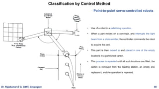
Point-to-point servo-controlled robots
• Use of a robot in a palletizing operation.
• When a part moves on a conveyor, and interrupts the light
beam from a photo emitter, the controller commands the robot
to acquire the part.
• This part is then moved to and placed in one of the empty
locations in a partitioned carton.
• This process is repeated until all such locations are filled, the
carton is removed from the loading station, an empty one
replaces it, and the operation is repeated.
Dr. Rajakumar D G, GMIT, Davangere 56
58.
Classification by ControlMethod
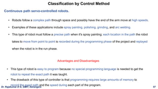
Continuous path servo-controlled robots.
• Robots follow a complex path through space and possibly have the end of the arm move at high speeds.
• Examples of these applications include spray painting, polishing, grinding, and arc welding.
• This type of robot must follow a precise path when it's spray painting; each location in the path the robot
takes to move from point to point is recorded during the programming phase of the project and replayed
when the robot is in the run phase.
• This type of robot is easy to program because no special programming language is needed to get the
robot to repeat the exact path it was taught.
• The drawback of this type of controller is that programming requires large amounts of memory to
record the exact path and the speed during each part of the program.
Advantages and Disadvantages
Dr. Rajakumar D G, GMIT, Davangere 57
Robot Specification
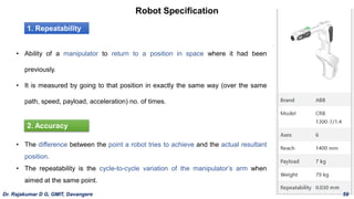
1. Repeatability
•Ability of a manipulator to return to a position in space where it had been
previously.
• It is measured by going to that position in exactly the same way (over the same
path, speed, payload, acceleration) no. of times.
• The difference between the point a robot tries to achieve and the actual resultant
position.
• The repeatability is the cycle-to-cycle variation of the manipulator’s arm when
aimed at the same point.
2. Accuracy
Dr. Rajakumar D G, GMIT, Davangere 59
61.
Robot Specification
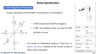
3. DOF(Degrees of Freedom)
• A body in 3D space can have 6 DOF (3 are Rotary & 3 are translatory).
• 6 DOF are positive & 6 DOF are negative.
• 3 DOF are translatory along +ve axis & 3 DOF
are along –ve axis.
• The number of independent motions in which the end
effector can move is defined by the number of axes of
motion of the manipulator.
Dr. Rajakumar D G, GMIT, Davangere 60
62.
Robot Specification
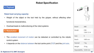
4. Payload
Ratedload carrying capacity:
• Weight of the object or the tool held by the gripper, without affecting other
functional characteristics.
• Overload leads to malfunctioning of the robot systems
5. Resolution
• The smallest increment of motion can be detected or controlled by the robotic
control system.
• it depends on the distance between the tool centre point (TCP) and the joint axis.
Dr. Rajakumar D G, GMIT, Davangere 61
63.
Robot Specification
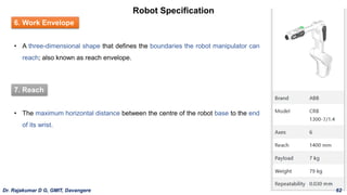
6. WorkEnvelope
• A three-dimensional shape that defines the boundaries the robot manipulator can
reach; also known as reach envelope.
7. Reach
• The maximum horizontal distance between the centre of the robot base to the end
of its wrist.
Dr. Rajakumar D G, GMIT, Davangere 62
64.
Robot Specification
Payload
Rated loadcarrying capacity: weight of the object or the tool held by
the gripper, without affecting other functional characteristics.
Overload leads to malfunctioning of the robot systems
Dr. Rajakumar D G, GMIT, Davangere 63
65.
Social Impact
1. Impactof Robotics on Direct Labour
• A robot performs multiple tasks, can be substituted for more than one human worker.
• Leading to the shift of direct labour to indirect labour activities
• Change in appointment strategy of new workers
• Set up of the work-space & operating robots needs education and training
• New workers need to have knowledge in installing, programming, inspecting, troubleshooting and
maintenance.
• Skill and education standard of the operator has to be improvised
• Labor unions have to be taken into confidence through sufficient prior notice.
• Minimum careful displacement of workers, new technological adaption, training and guidance.
• Convincing the security of job is a serious task
Dr. Rajakumar D G, GMIT, Davangere 64
66.
Social Impact
2. ProfessionalAdjustment Impact
• With the advancement in automation, professional & semi-professional employees have to be familiar
with & expertise in computer programming, robot maintenance optimization of processes etc.,
• Engineers from specialization in machine design, machine tool technology, control engineering,
electronics & computer science can fulfil the needs of professionals in the robot industries.
Dr. Rajakumar D G, GMIT, Davangere 65
67.
Social Impact
3. Needfor Education & Training
Present educational standards has to be revised to take care of
a) Highly educated force
b) Shortage of robot technicians
c) Deficiency in programmers
d) Well equipped laboratory facilities & instructors
e) Short fall in training institutes
f) Consultants to re-train the existing employees
Dr. Rajakumar D G, GMIT, Davangere 66
68.
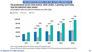
THE ROBOTICS MARKETAND THE FUTURE PROSPECTS
• Annual sales of robots have been growing worldwide
• Traditionally, it was the automotive industries that led the drive to robotize
• In the last decade, the growth of non-automotive robots has been higher than automotive robots.
• Surge in robotics investments: fall of robot prices, increased labour cost, increased accuracy, speed,
versatility, shrinking workforce in several developed countries and ageing population
Dr. Rajakumar D G, GMIT, Davangere 67
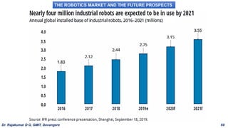
69.
THE ROBOTICS MARKETAND THE FUTURE PROSPECTS
Dr. Rajakumar D G, GMIT, Davangere 68
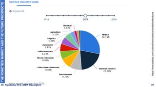
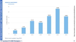
70.
THE ROBOTICS MARKETAND THE FUTURE PROSPECTS
Dr. Rajakumar D G, GMIT, Davangere 69
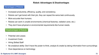
Robot: Advantages &Disadvantages
• Increased productivity, efficiency, quality, and consistency.
• Robots can’t get bored with their job, they can repeat the same task continuously.
• More accurate than humans.
• Robots can work in unsafe environments (chemical factories, radiation zone, etc.)
• They don’t have physical or environmental requirements like human needs.
• Potential Job Losses
• Investment Costs
• Hiring Skilled Staff
• No analytical ability: Don’t have the power to think, analyze & create by taking information from surroundings
• Over-dependence on technology
Advantages of Robots
Disadvantages of Robots
Dr. Rajakumar D G, GMIT, Davangere 72
74.
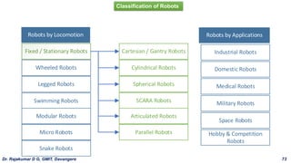
Robots by Locomotion
Fixed/ Stationary Robots
Wheeled Robots
Legged Robots
Swimming Robots
Modular Robots
Micro Robots
Snake Robots
Robots by Applications
Industrial Robots
Domestic Robots
Medical Robots
Military Robots
Space Robots
Hobby & Competition
Robots
Cartesian / Gantry Robots
Cylindrical Robots
Spherical Robots
SCARA Robots
Articulated Robots
Parallel Robots
Classification of Robots
Dr. Rajakumar D G, GMIT, Davangere 73