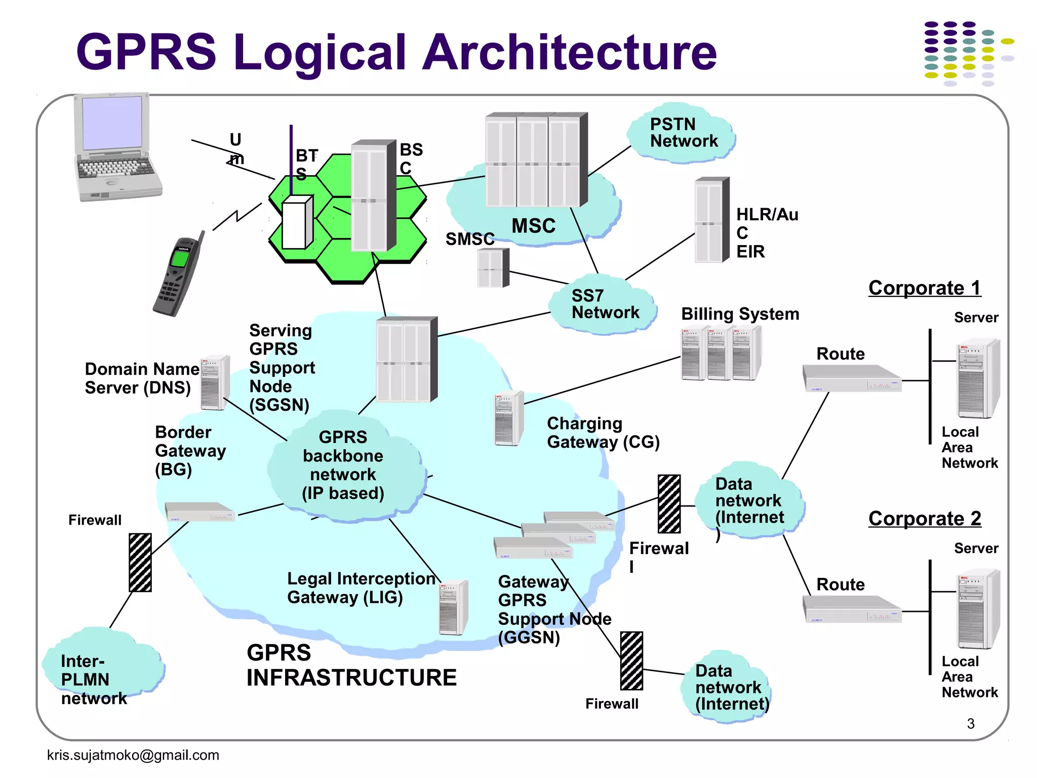
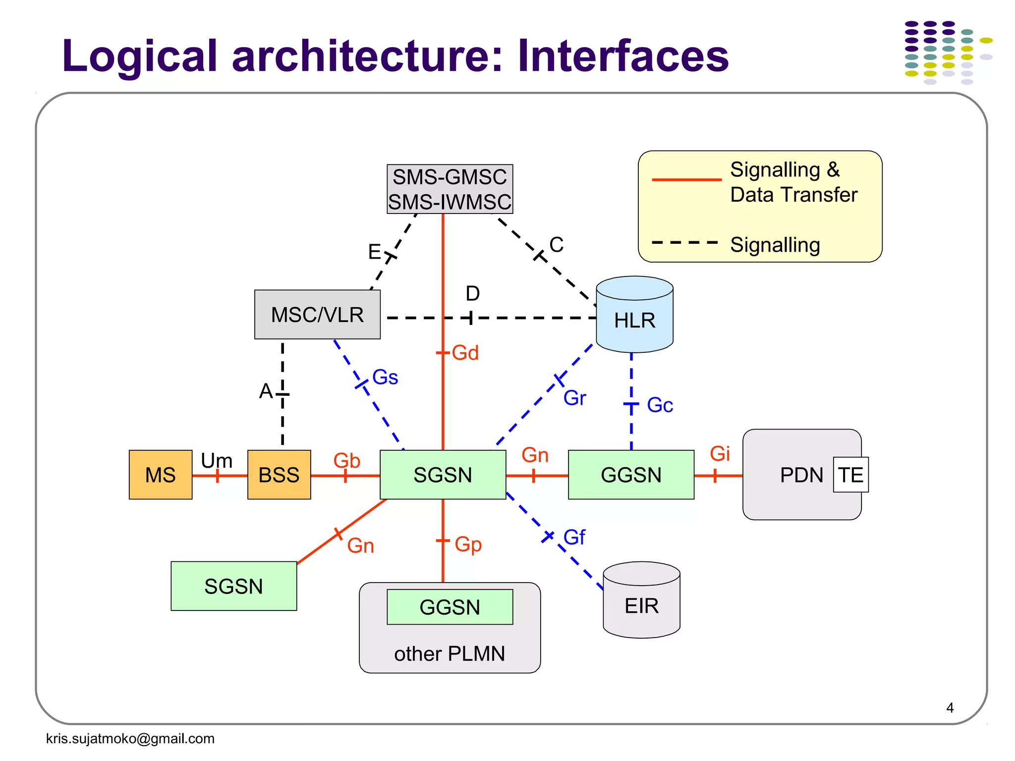
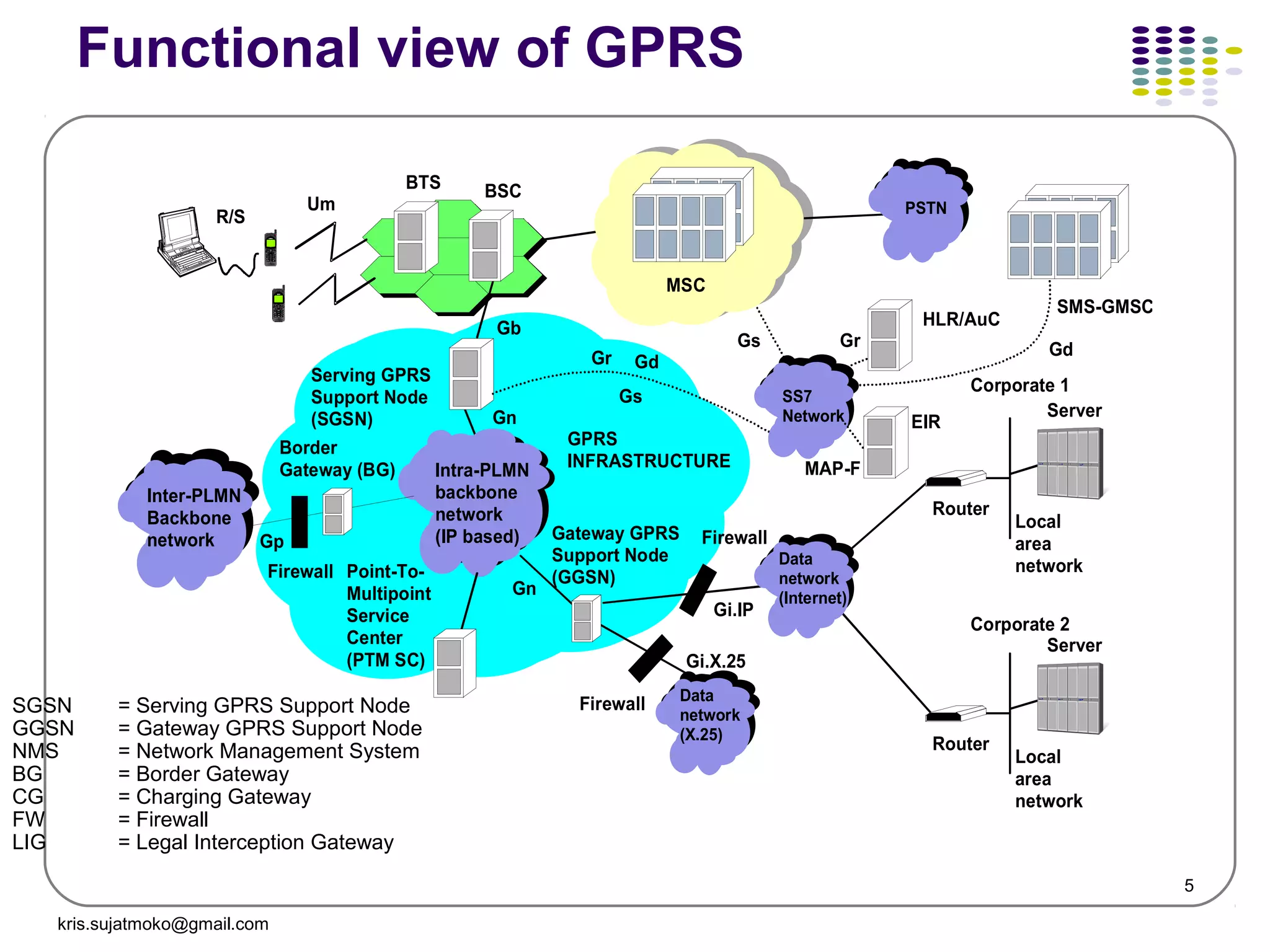
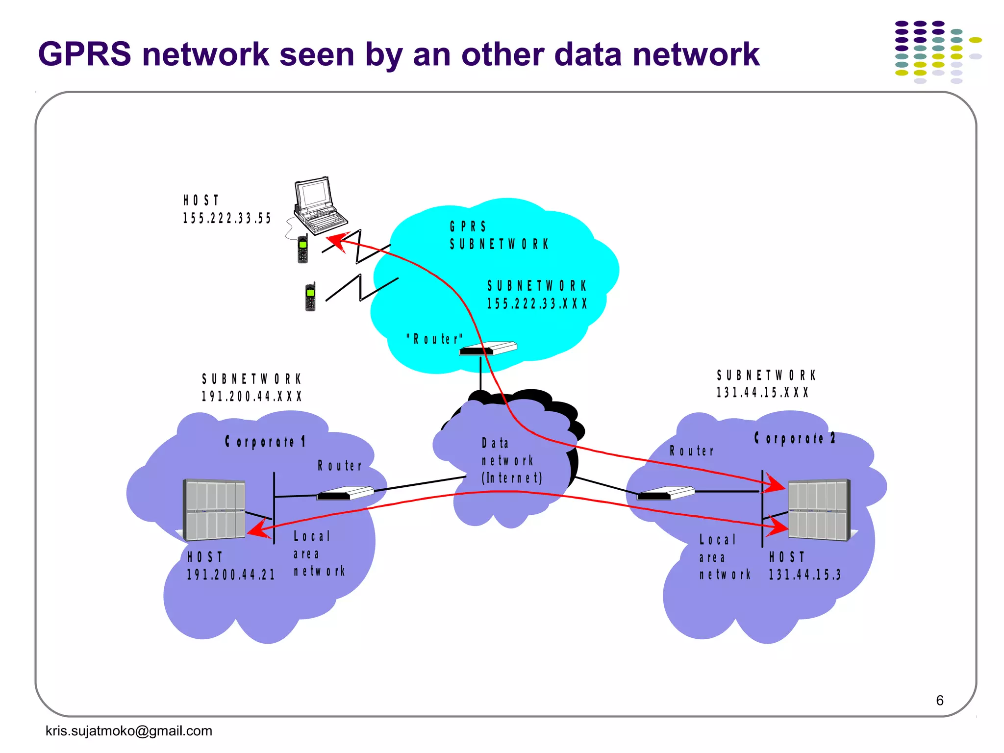
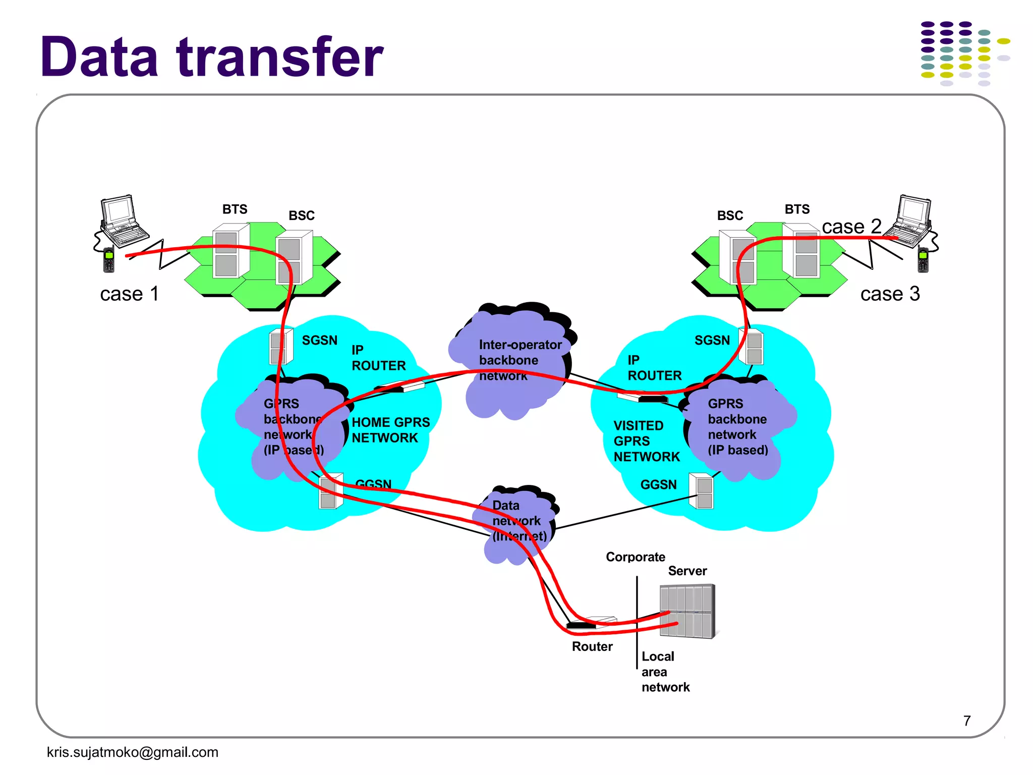
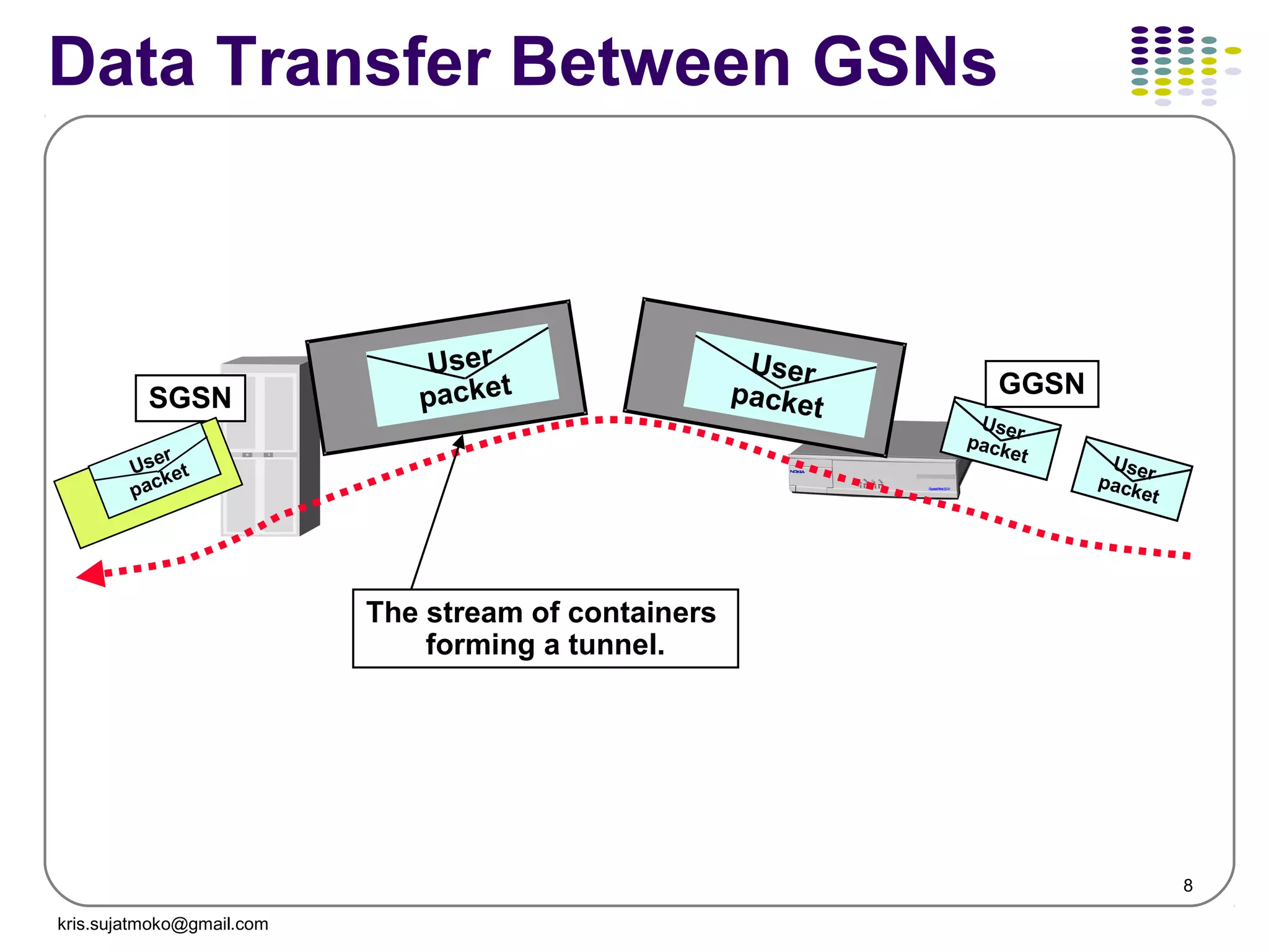
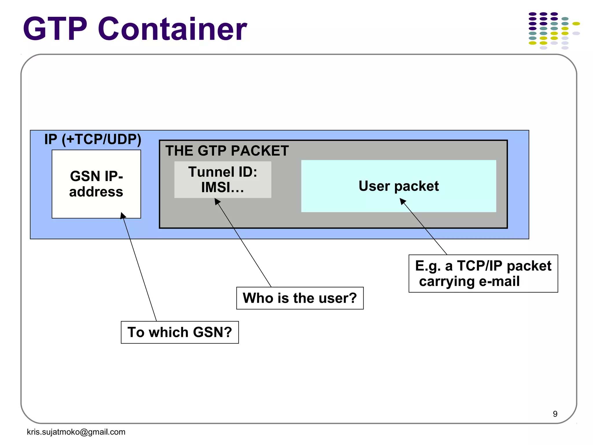
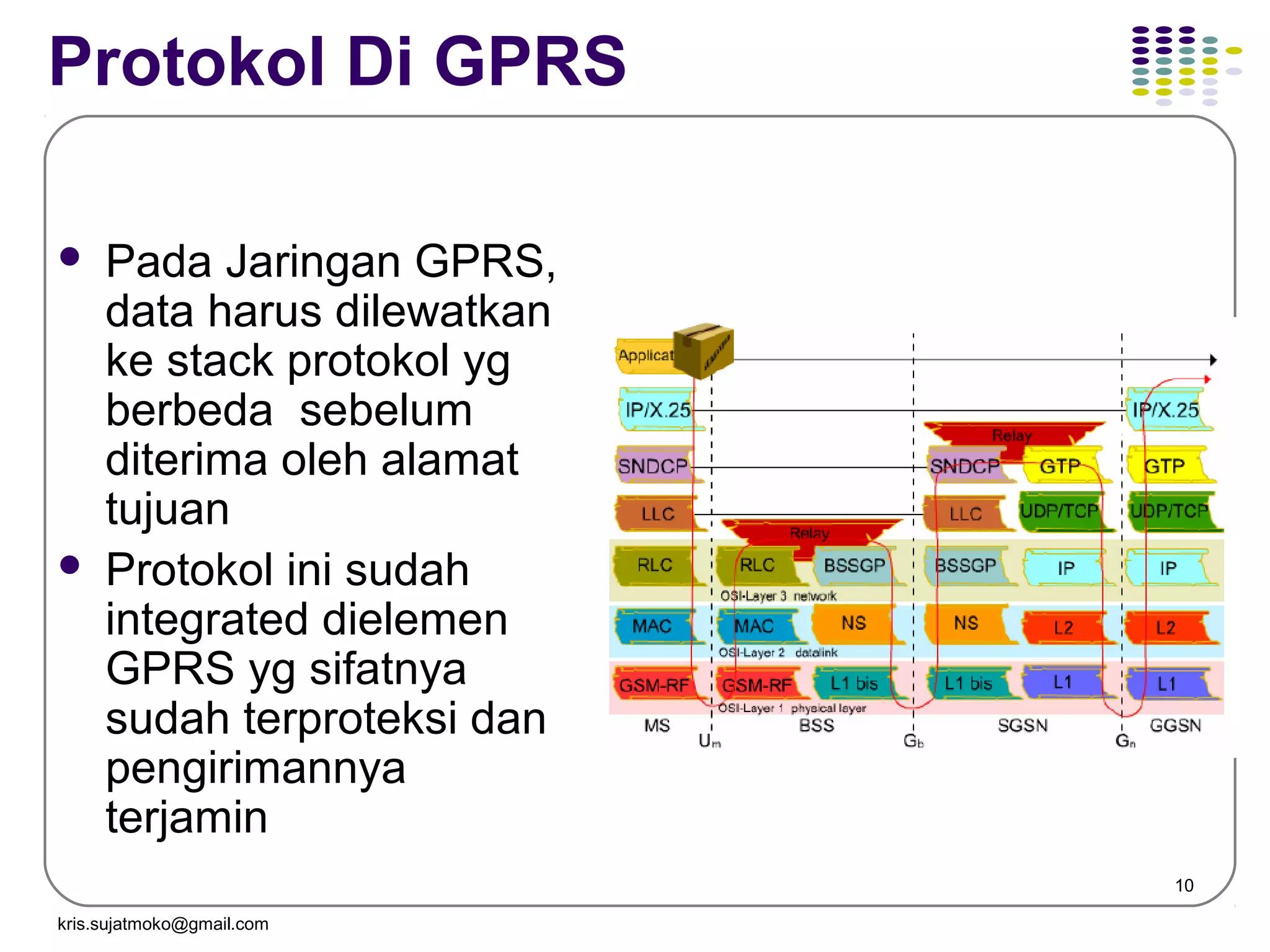
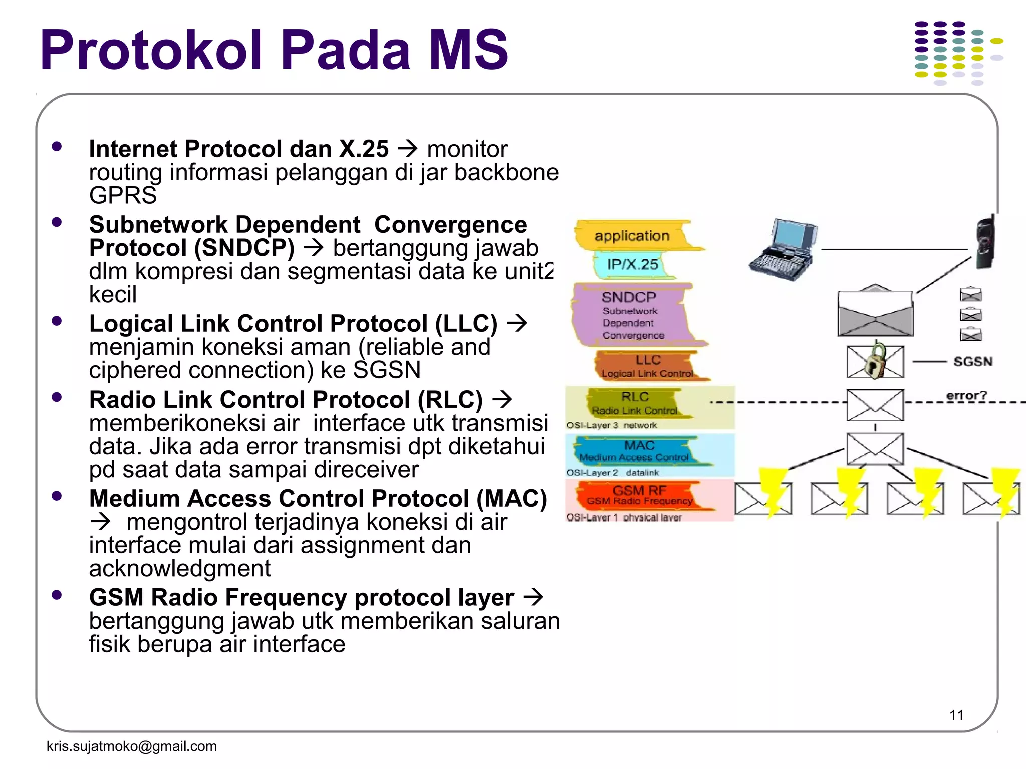
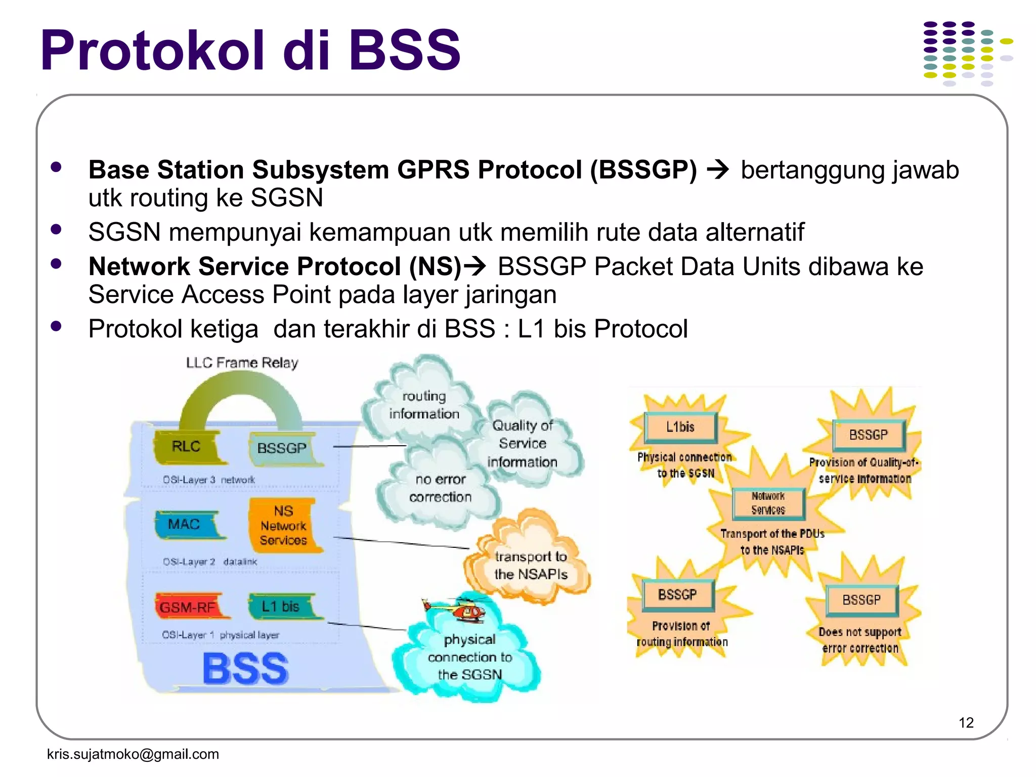
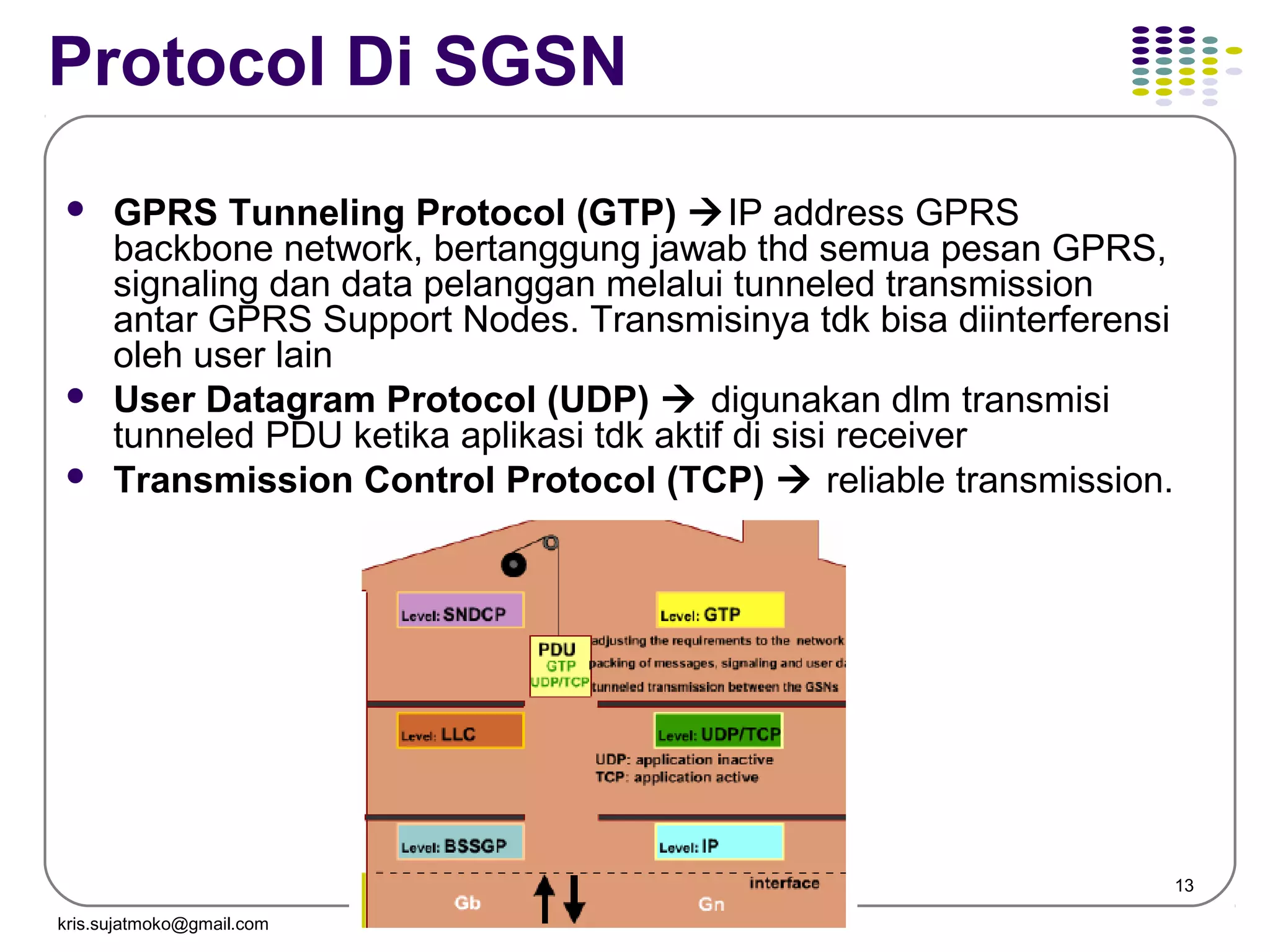
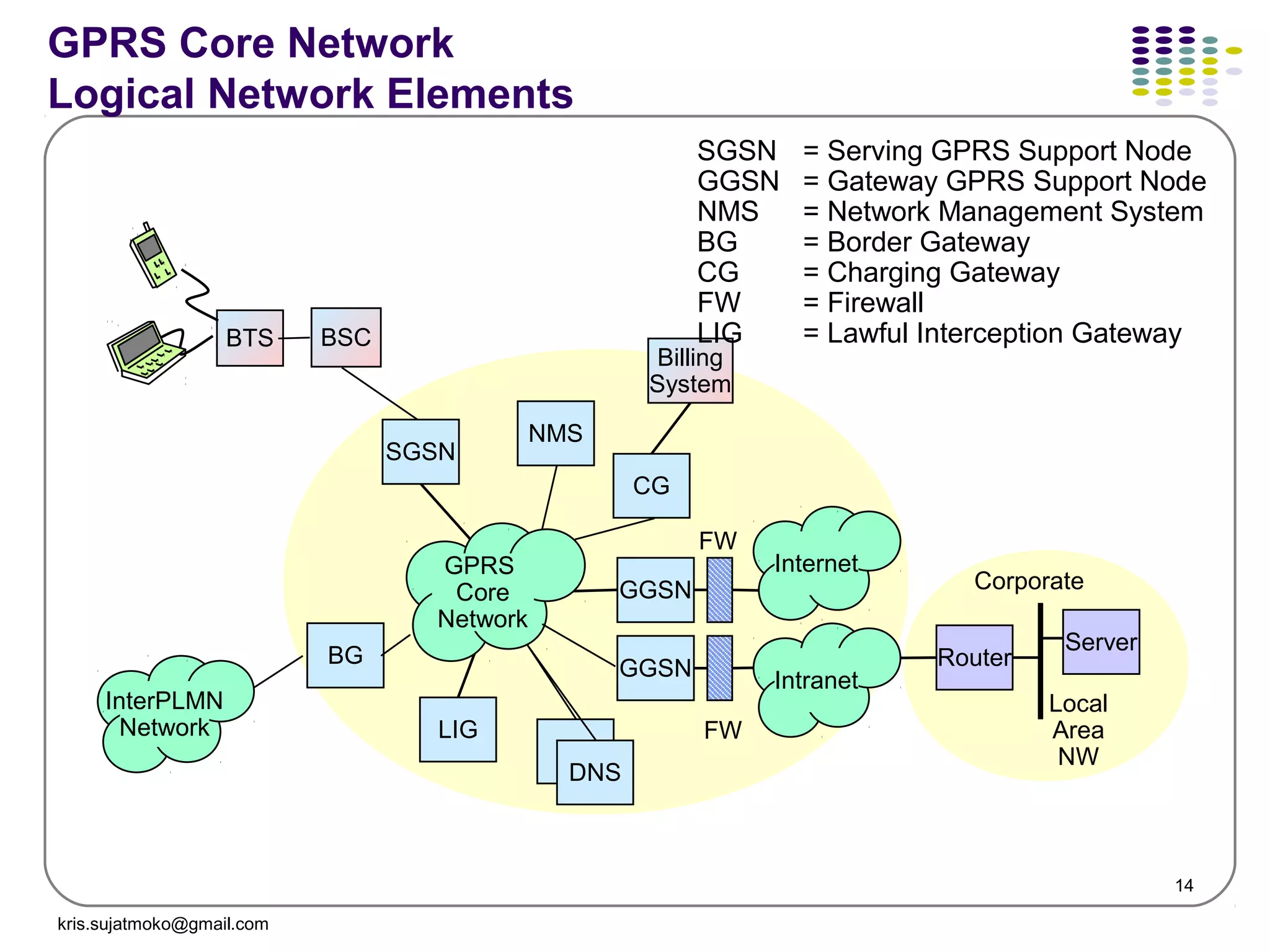
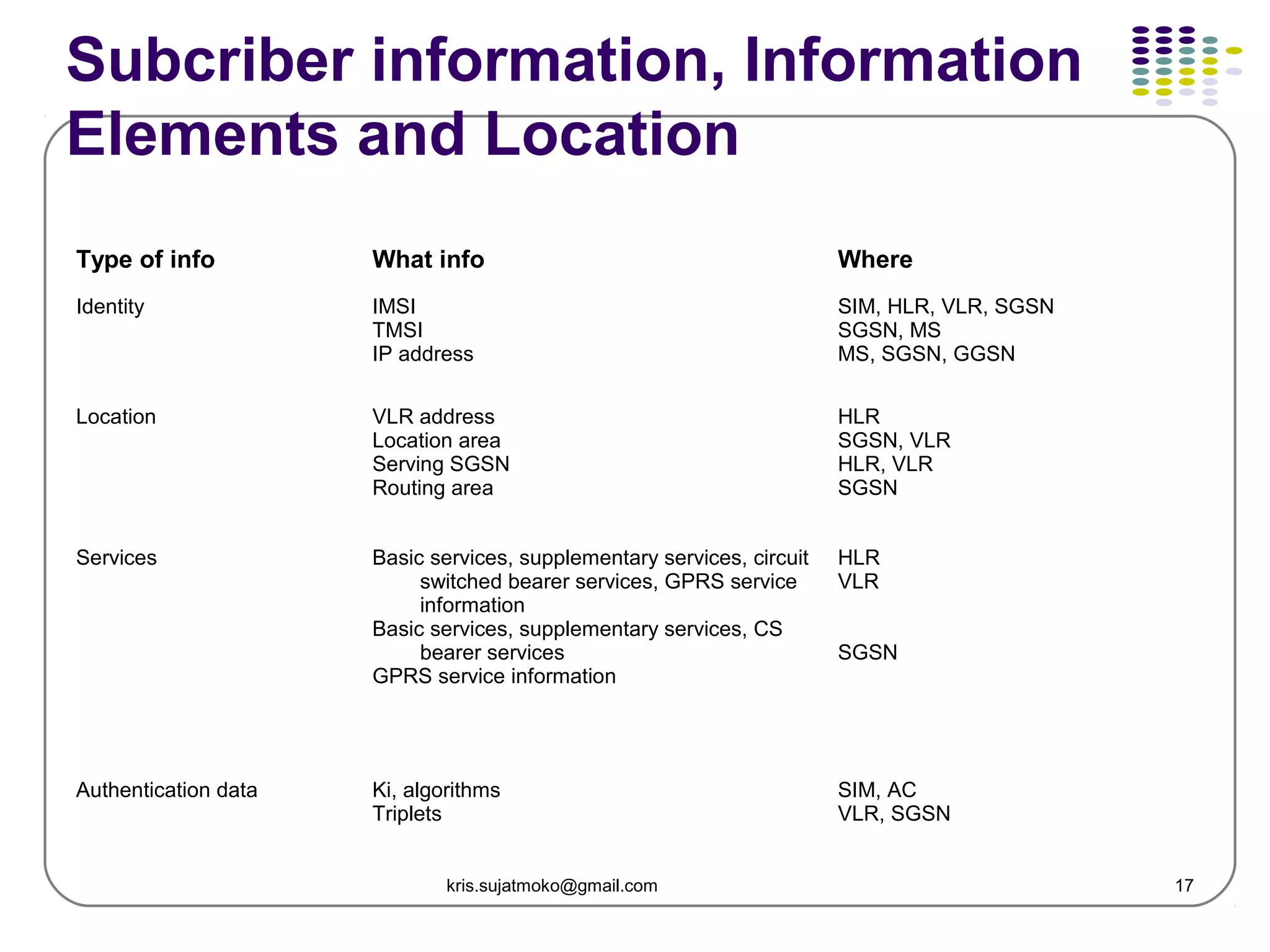
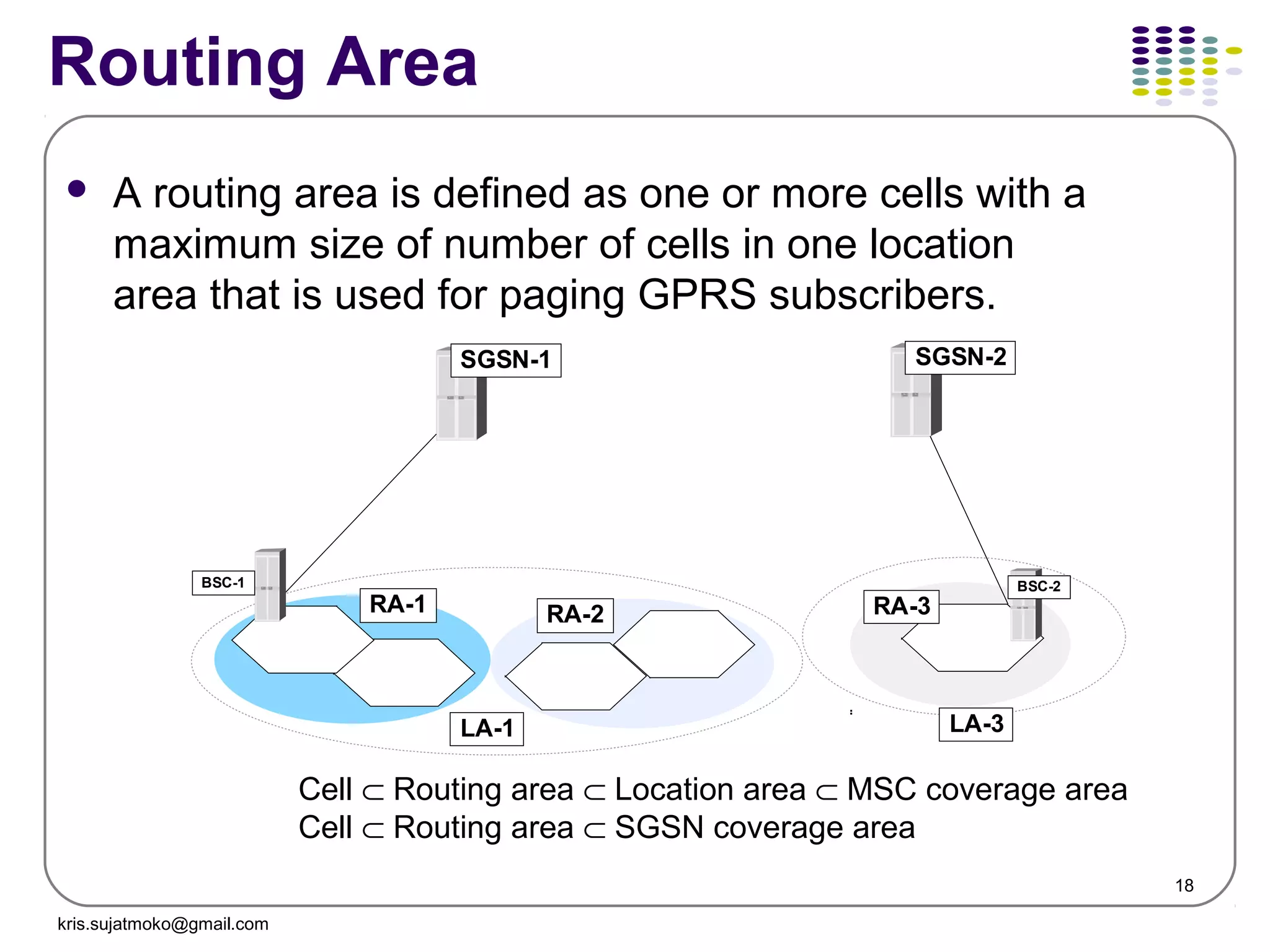
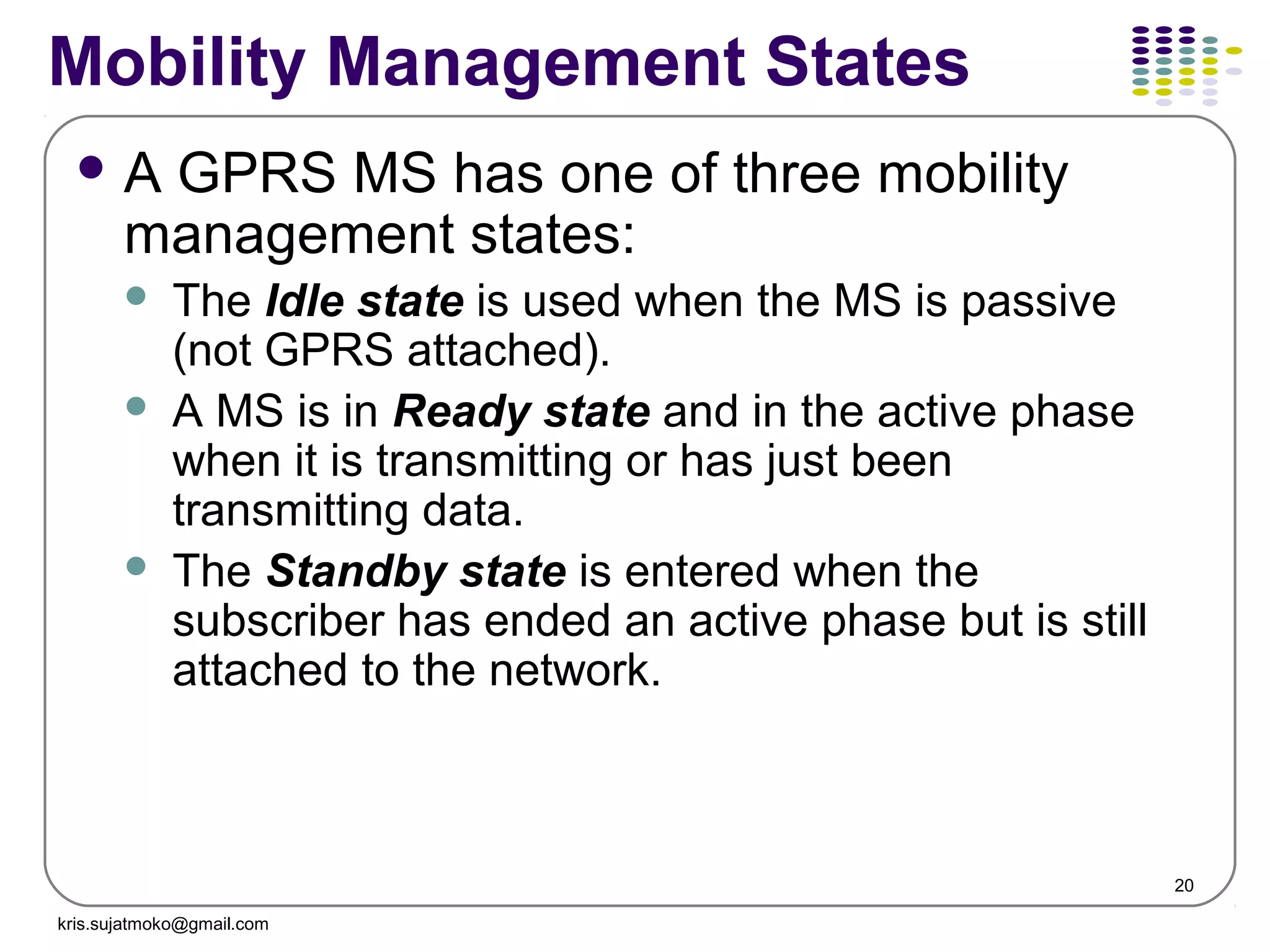
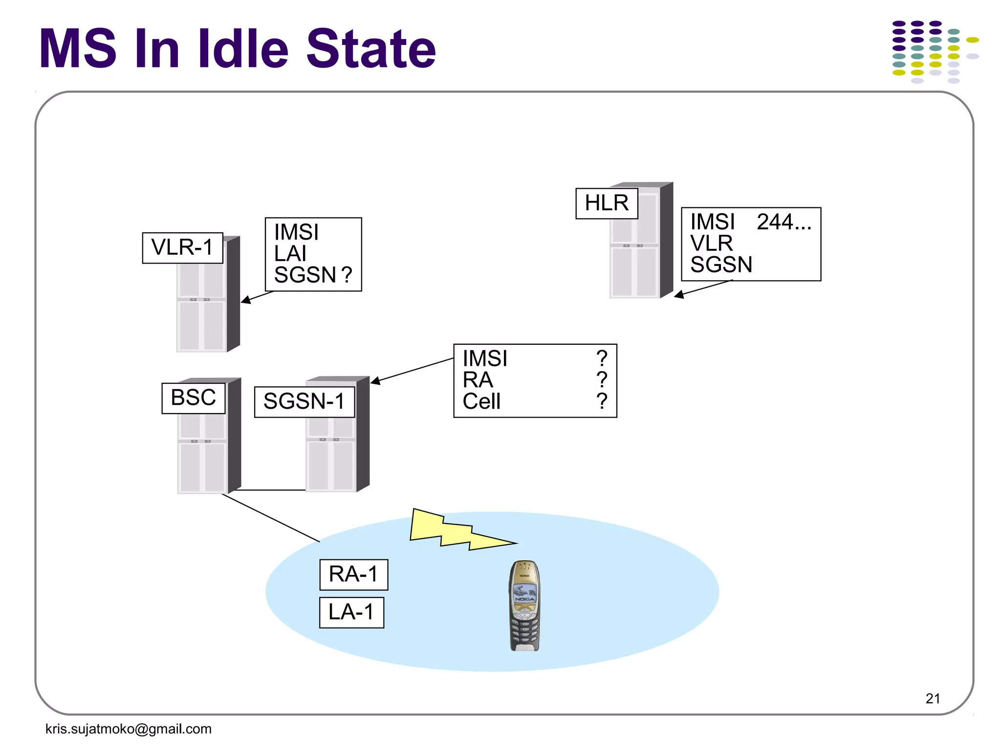
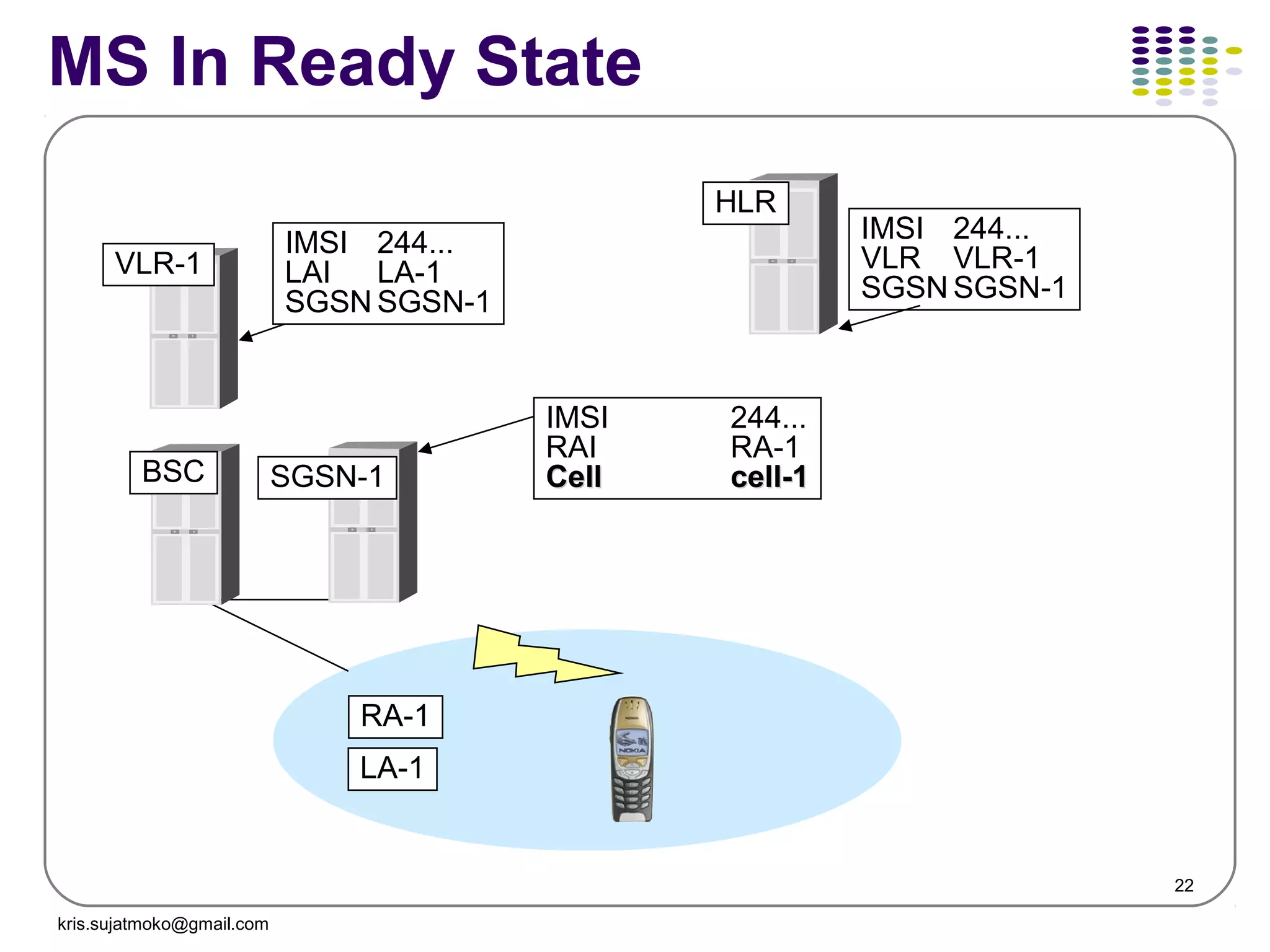
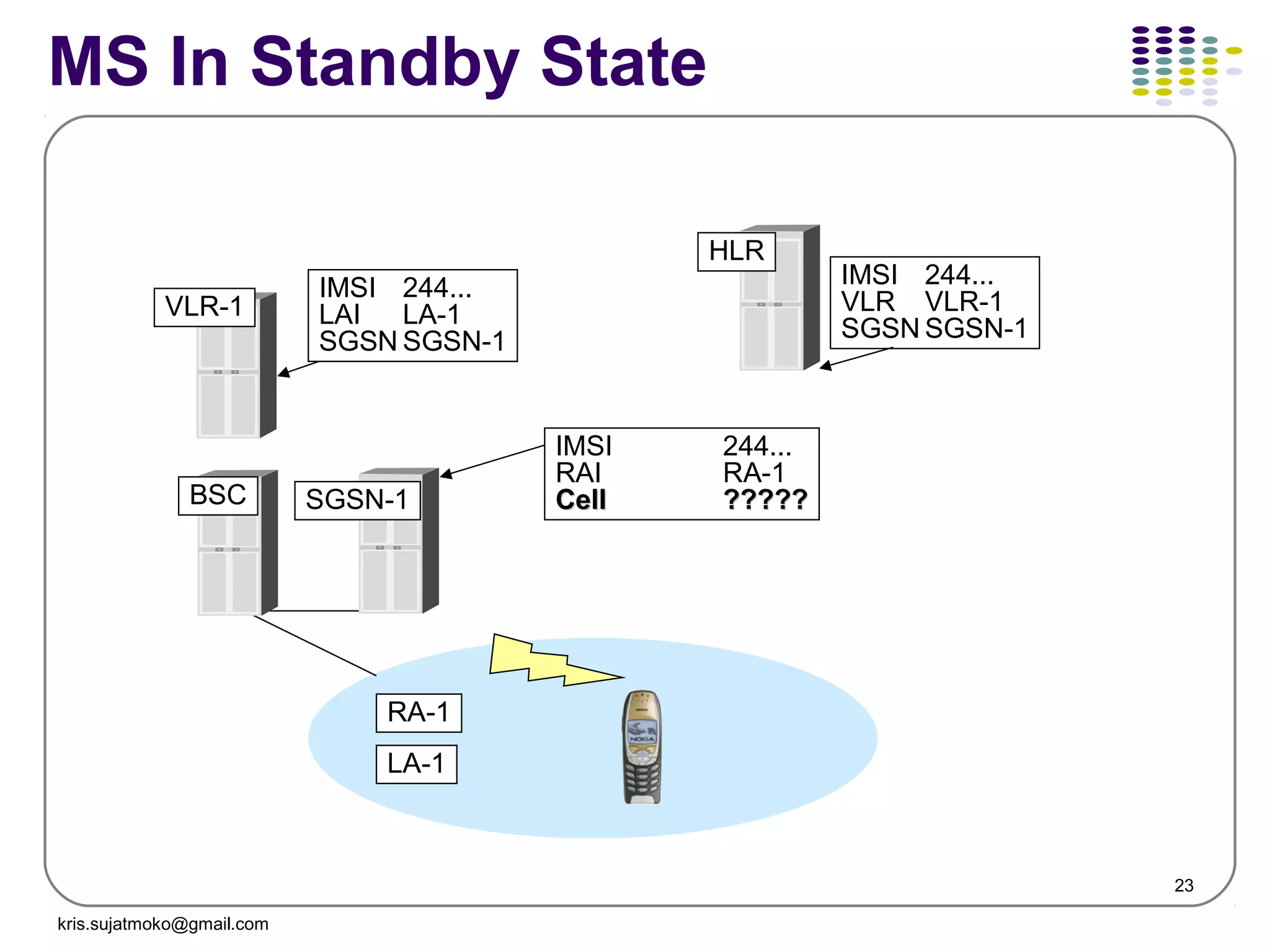
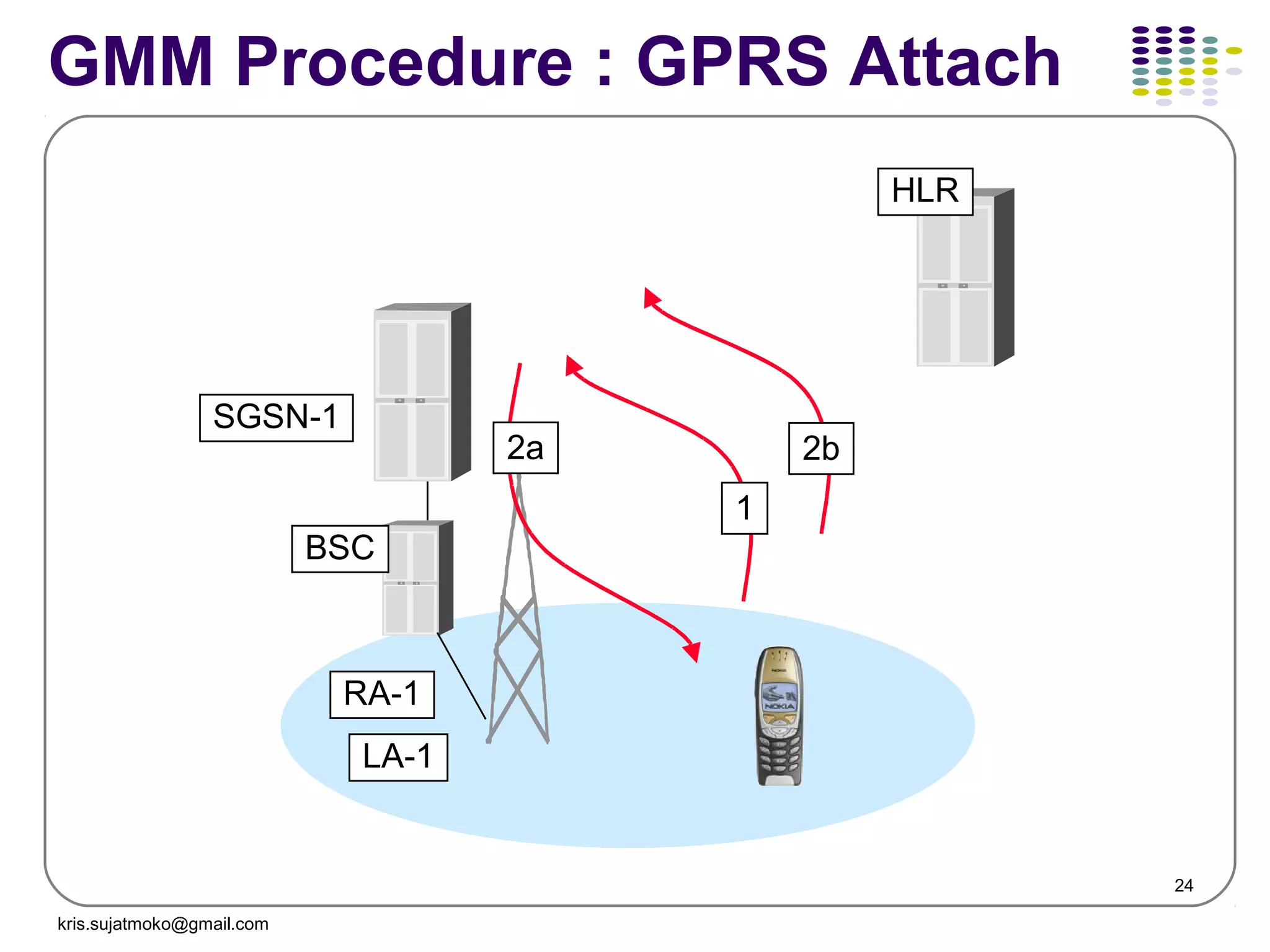
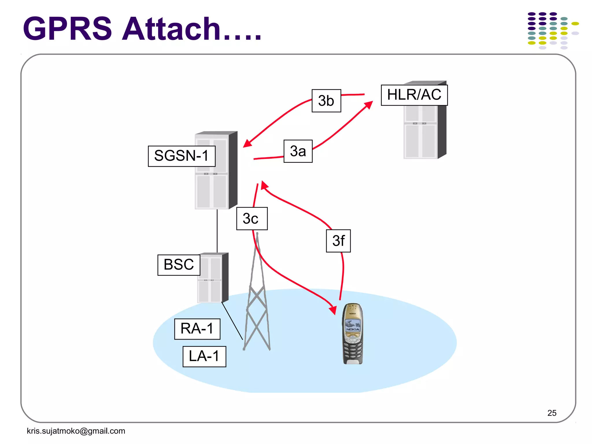
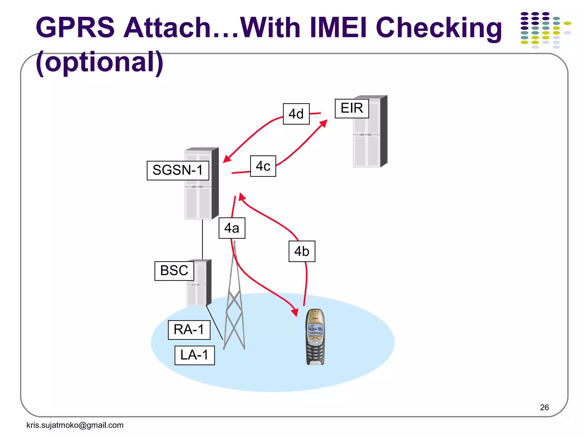
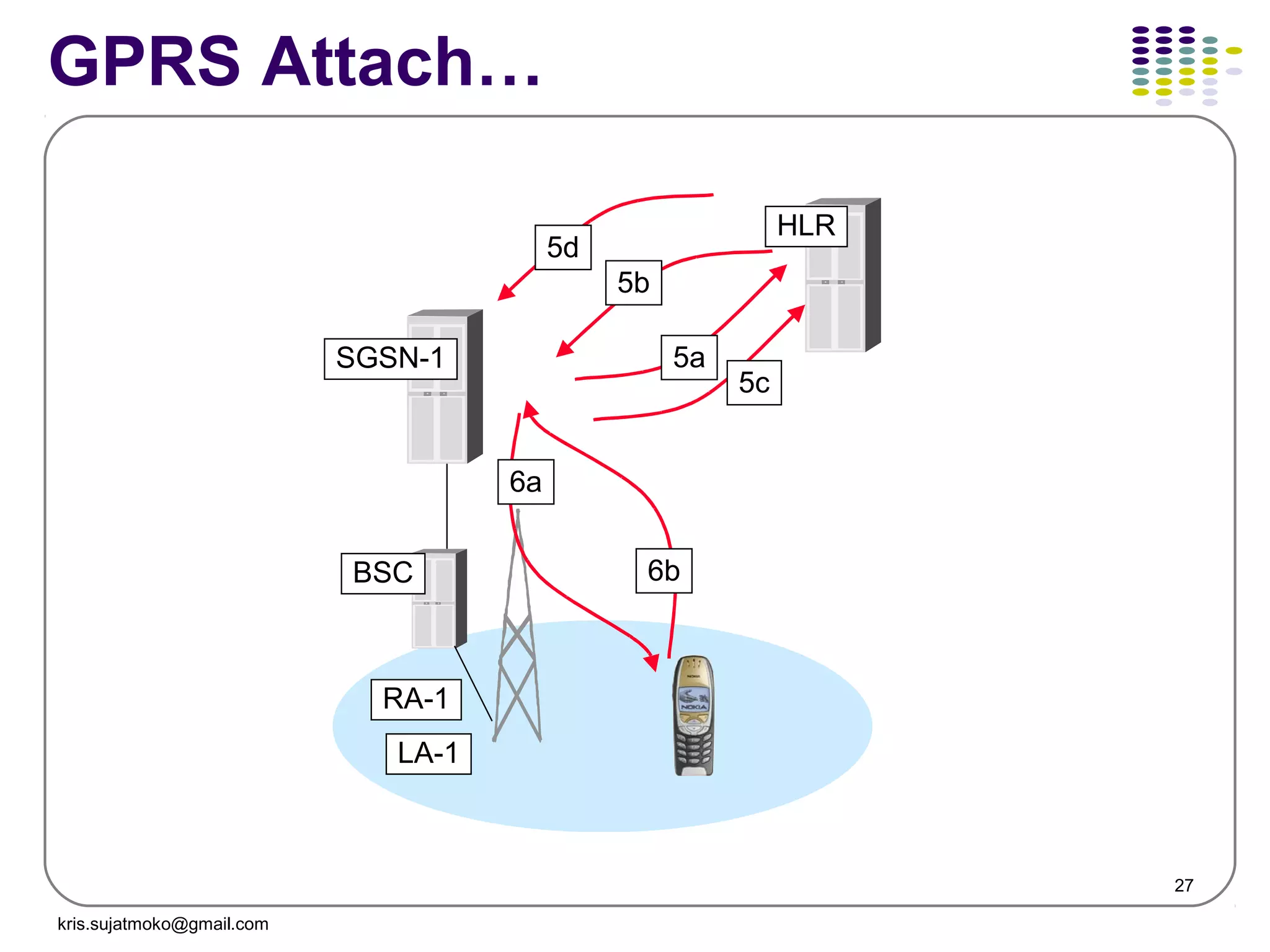
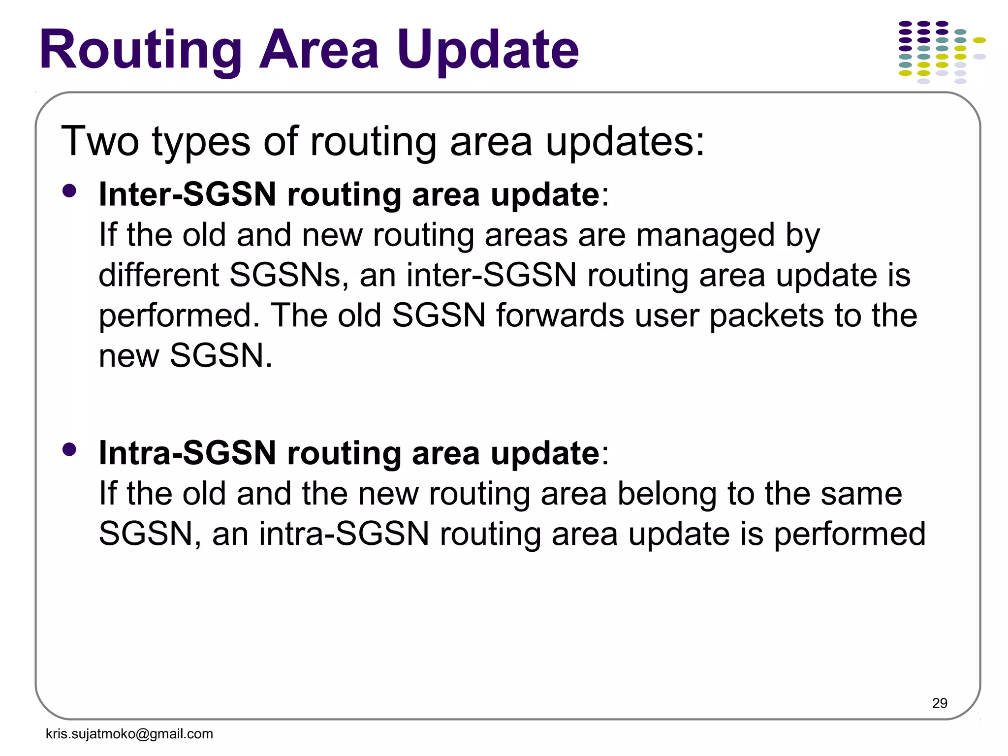
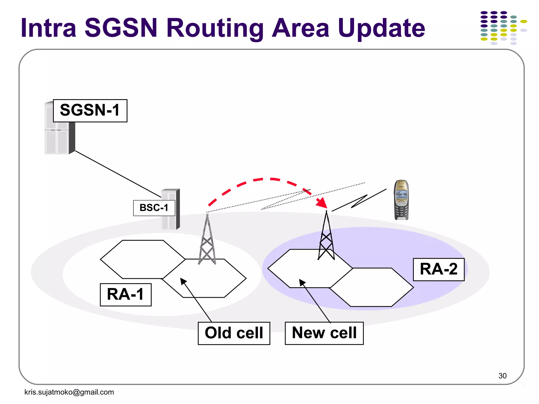
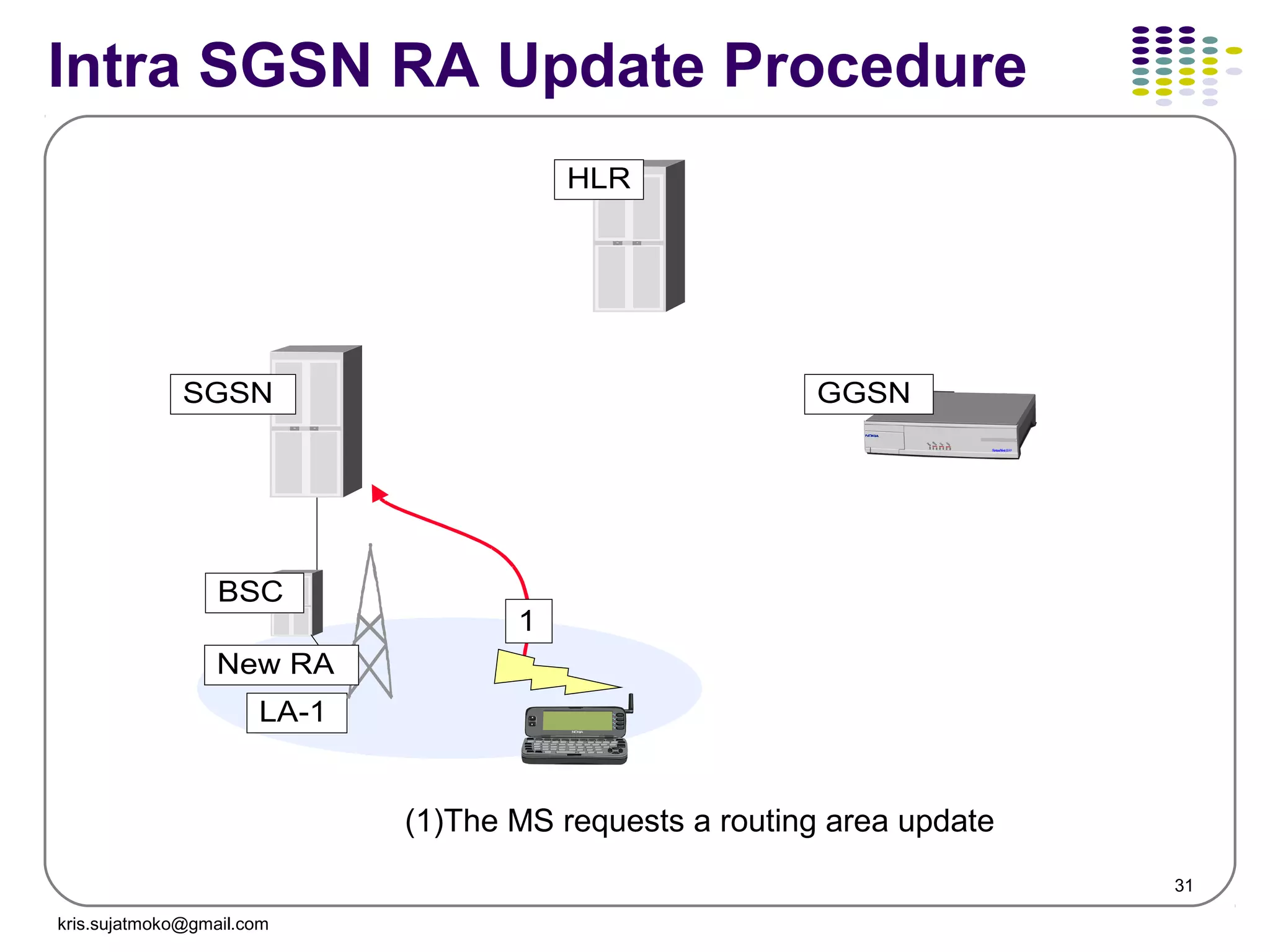
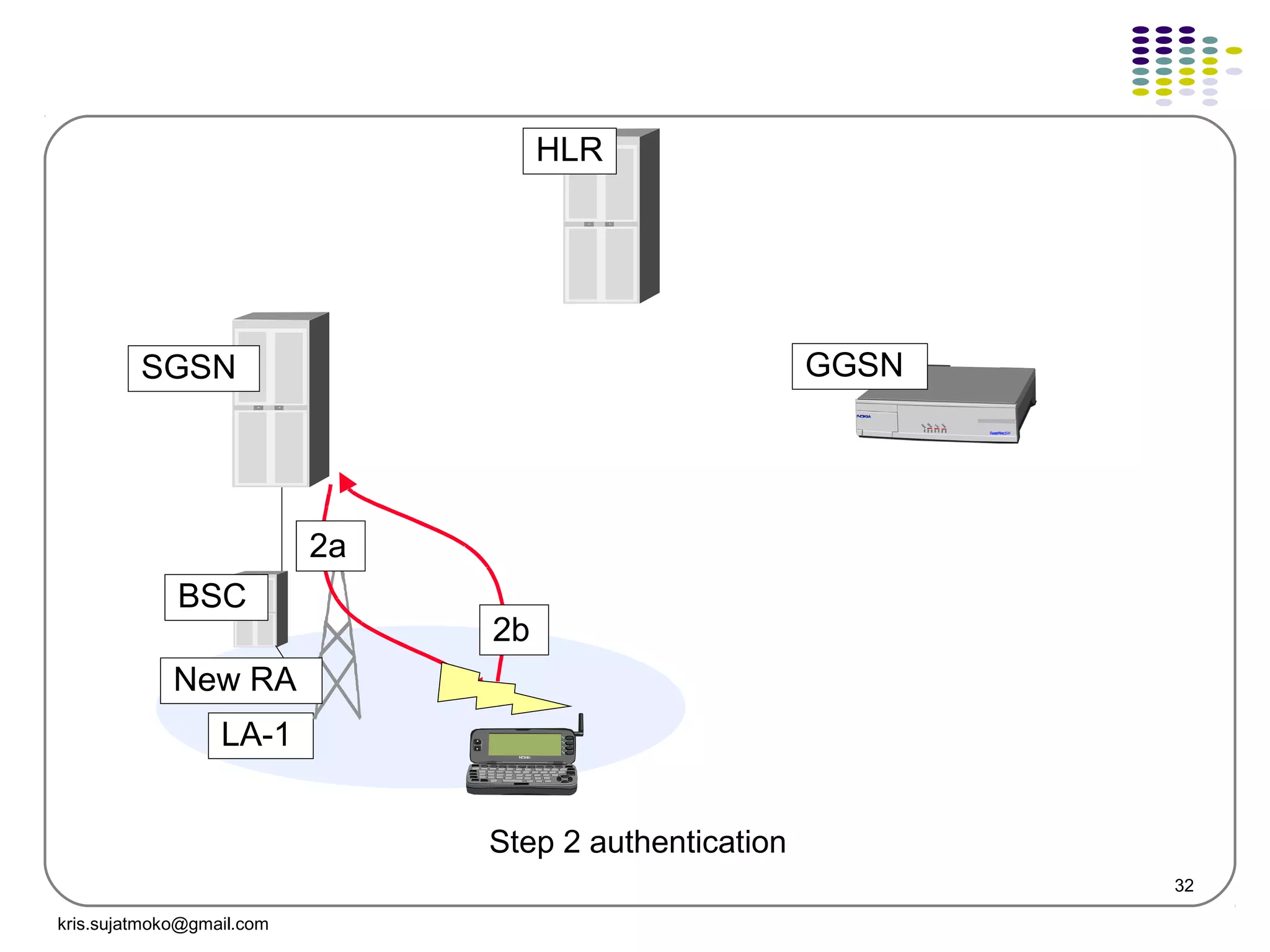
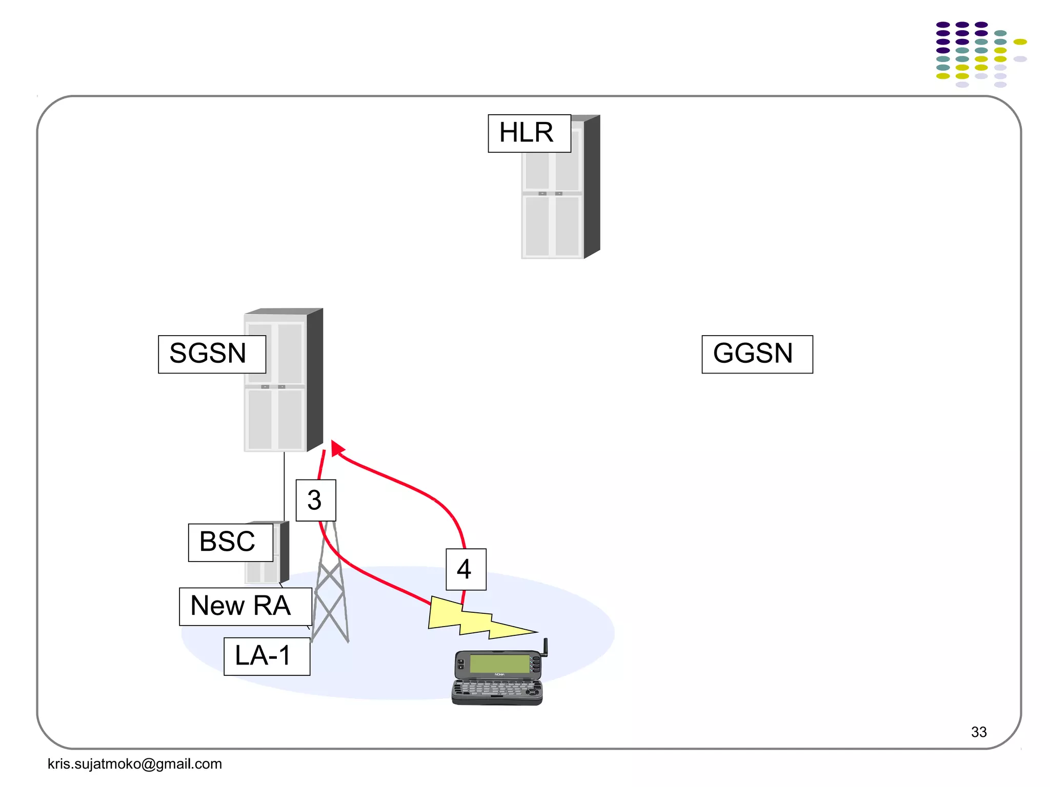
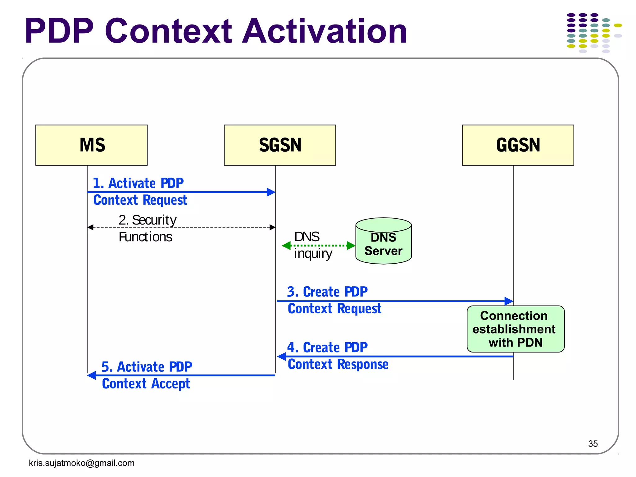
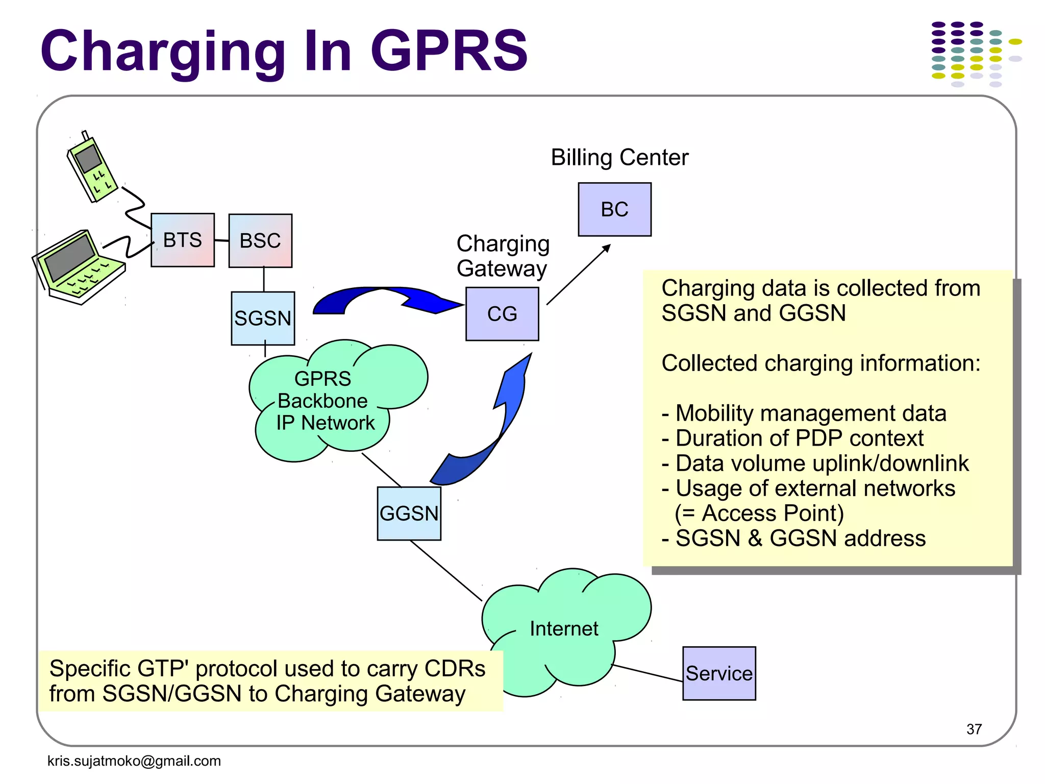
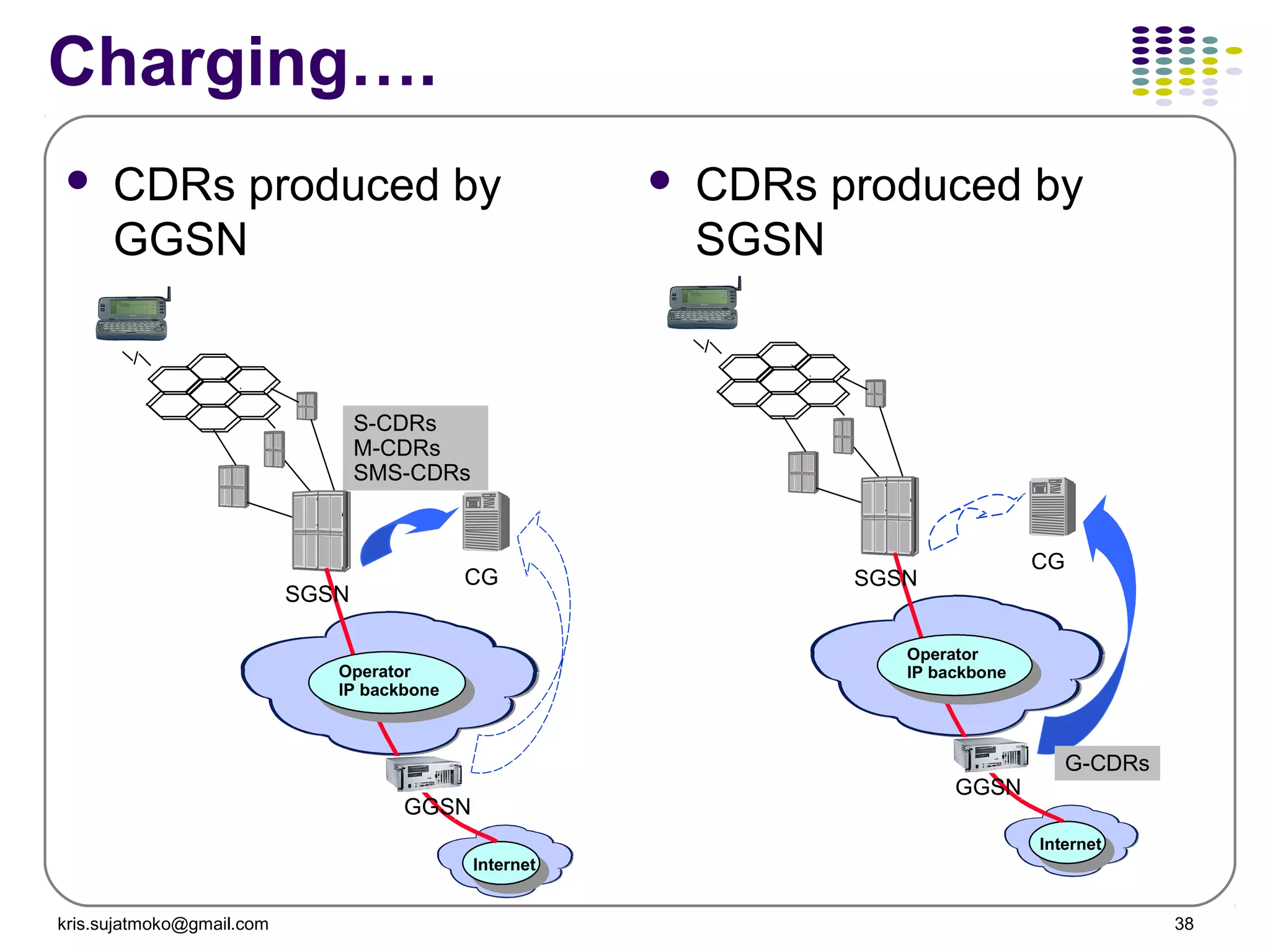
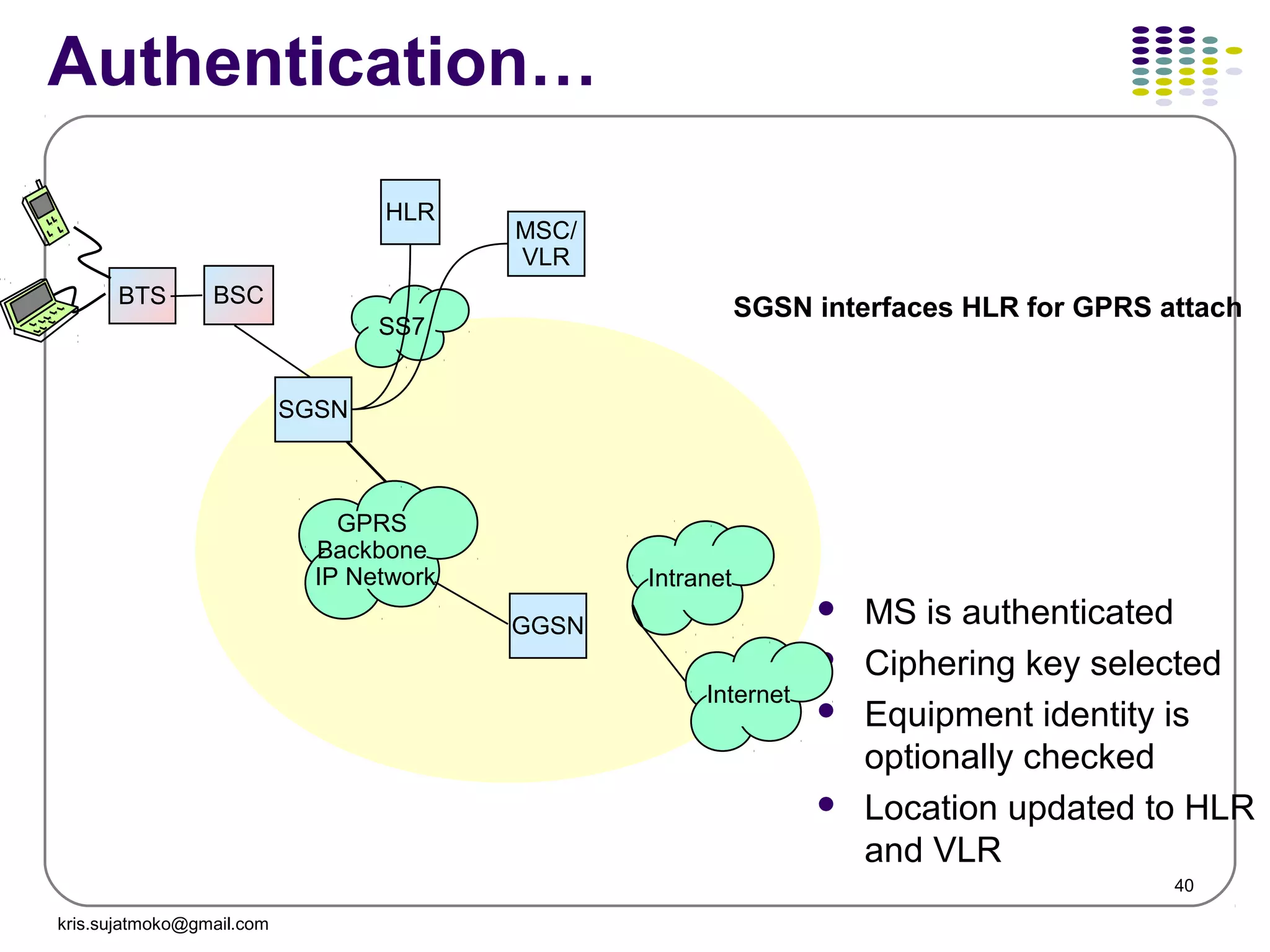
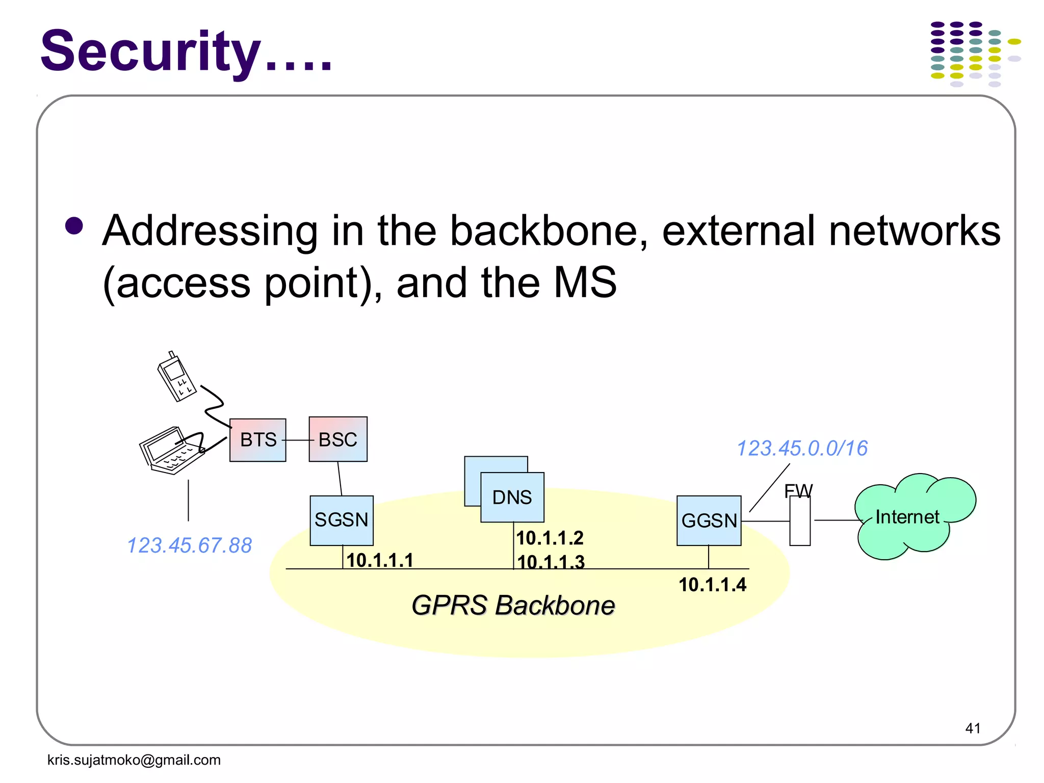
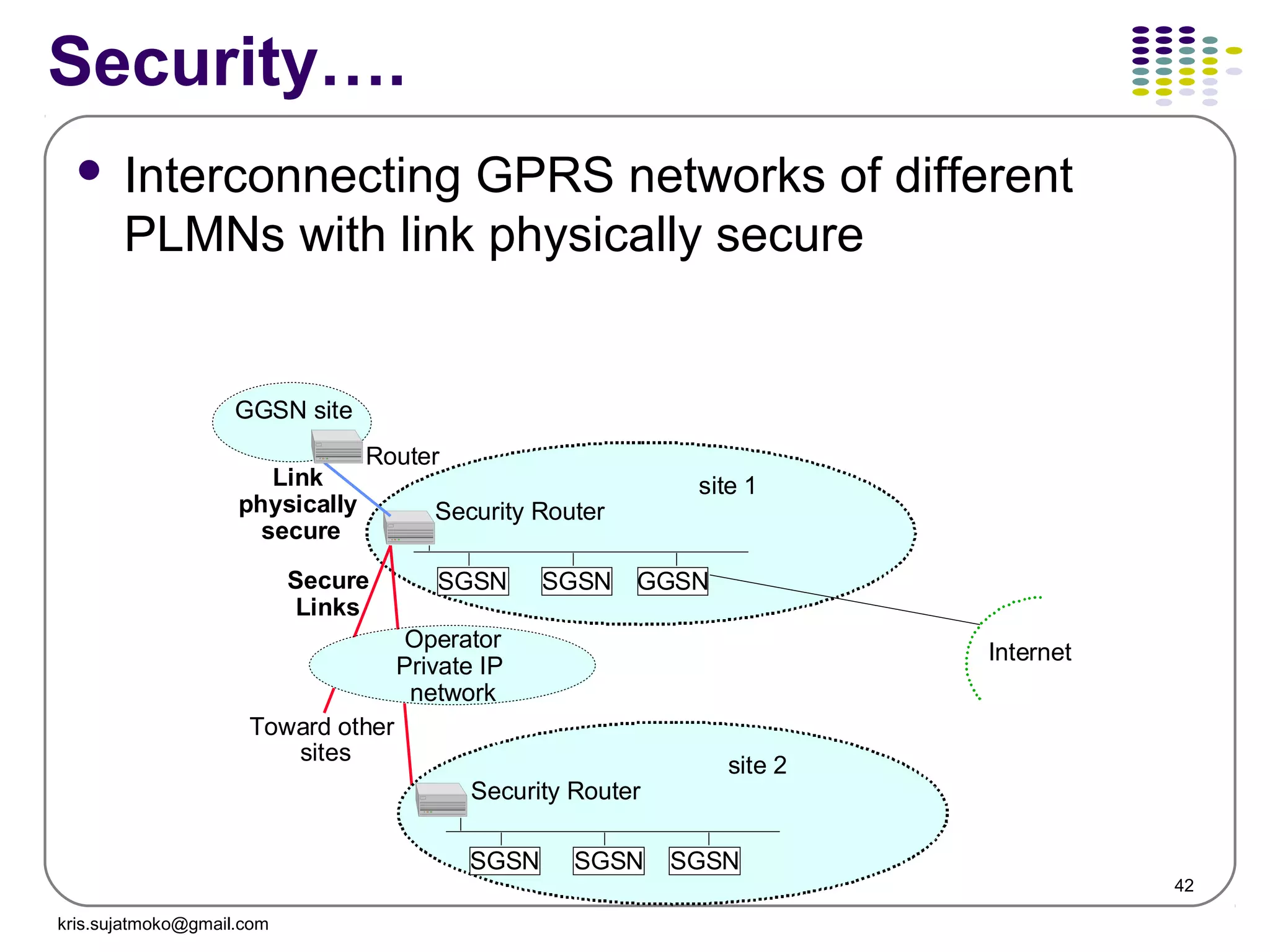
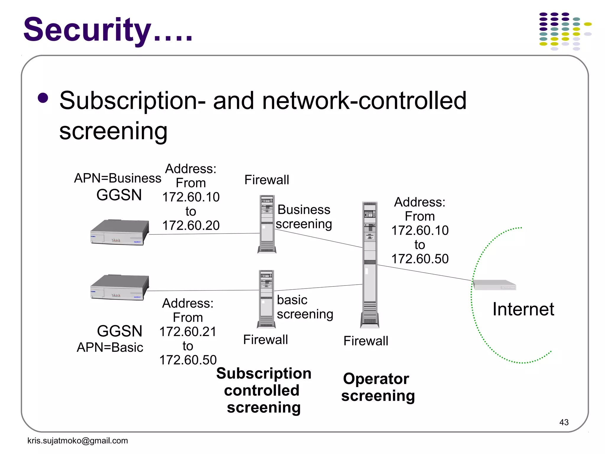
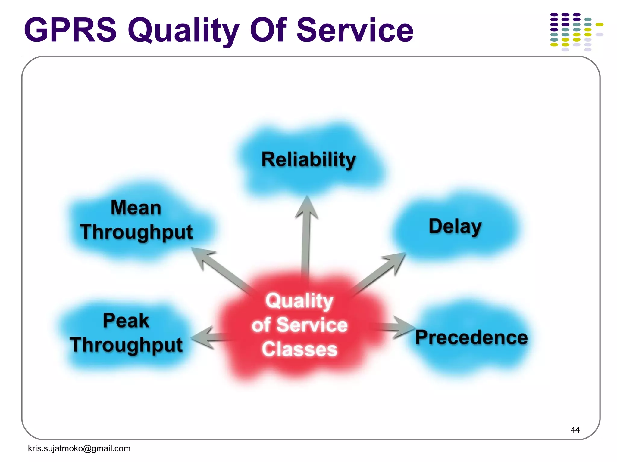
The document discusses GPRS operations and procedures. It provides an overview of GPRS architecture, protocols used in GPRS, mobility management procedures like GPRS attach and routing area update, and location management in GPRS. Diagrams are included to illustrate logical architecture, data transfer between network elements, and mobility states of a GPRS mobile station.
Gsm architecture, gsm network identities, network cases, cell planning, and c...Zorays Solar Pakistan
This document discusses GSM network architecture and components. It describes the key elements like the MSC, HLR, VLR and their functions. It explains cell planning and frequency reuse. It also covers network identities, attaching and roaming processes, call setup, and charging systems like triggered charging for calls and SMS. Compound charging processes for originating calls, voucher refills through IVR are summarized.
This document summarizes GSM architecture and call flows, including inter-MSC and intra-MSC call flows. Inter-MSC call flow occurs between two different MSCs, while intra-MSC call flow is between two BSCs within the same MSC. The inter-MSC call flow involves signaling between the BSC, MSC-O, MSC-T, HLR, and RNC to set up and release the call bearers. The intra-MSC call flow involves signaling between the MS-O, BSC-O, MSC/VLR, MGW, HLR, BSC-T, and MS-T to authenticate, set up, and release call bearers within a single MSC
This document discusses optimization of networks using drive testing and TEMS software. It provides information on:
1) How drive testing and TEMS can analyze network performance from a subscriber perspective by recording measurement data.
2) The types of information displayed in TEMS windows including cell identity, signal strength, quality, and timing advance measurements.
3) How to use the TEMS software including default tabs, maps, recording properties, and report generation.
RRC protocols in LTE help manage radio resources and signaling between the UE and network. Key aspects include:
1. RRC defines two UE states - RRC_CONNECTED for active data transfer and RRC_IDLE for idle/paging.
2. Signaling Radio Bearers (SRBs) carry RRC and NAS messages using different logical channels.
3. System information is broadcast on common channels, informing UEs of network configurations and neighbor cells.
4. Handover between cells is supported through the X2 interface for intra-LTE handovers and inter-RAT handovers to other technologies like UMTS or GSM.
The document discusses GPRS network architecture and processes. It describes how a mobile station (MS) attaches to and detaches from the GPRS network by communicating with the SGSN and HLR. It also describes how a temporary block flow (TBF) is established to enable data transfer between the MS and network. Additionally, it outlines how a packet data protocol (PDP) context is activated and deactivated to manage the subscriber's data session.
UMTS-WCDMA is a 3G mobile communication standard that uses CDMA technology. It uses wideband CDMA with a chip rate of 3.84 Mcps for its air interface along with orthogonal variable spreading factor codes. The standard defines protocols and procedures for cell search, handover, uplink and downlink physical channels, and support for multirate services through variable spreading factors. Long term targets for UMTS-WCDMA evolution include higher data rates up to 100 Mbps for full mobility and 1 Gbps for low mobility, as well as improved spectral efficiency.
This document outlines the process for mobile originated and terminated calls in 3G networks. It describes the steps for a mobile originating call in 3 parts and a mobile terminated call in 3 parts, including setting up the GTP tunnel for transport. The document breaks down the end-to-end call flows for 3G connections.
Mobile networks have evolved over several generations from 1G analog cellular to 4G LTE networks. This document provides an overview of the fundamental concepts and evolution of mobile networks including discussions of 2G, 3G, 4G networks and the Evolved Packet Core. It describes the core network functions and interfaces as well as basic network scenarios.
The document describes the key components of a GSM network and their functions:
- The BTS handles radio transmissions and defines each cell. The BSC manages radio resources and handles handovers between BTSs. The MSC performs switching between mobile and other networks.
- The HLR is a central database that stores subscriber information. The VLR temporarily stores subscriber data needed by the local MSC. The EIR stores valid device IDs. The AUC authenticates users and protects the network from fraud.
Together, these components enable functions like call setup, location updates, authentication, and mobility as users move between cells in a GSM network.
The document discusses different types of location updating procedures in mobile networks:
1. Location updating type normal occurs when a mobile subscriber (MS) moves to a new location area and needs to update the network of its new location.
2. IMSI attach is used when the MS powers back on in the same location area it was in when it entered detached mode.
3. Periodic registration is used to avoid unnecessary paging and prevent database failures. The MS registers at periodic intervals set by the network operator, from every 6 minutes to every hour.
GSM is a second generation cellular standard developed to provide voice services and data delivery using digital modulation. It was developed by Groupe Spécial Mobile in 1982 to replace incompatible analog cellular systems. GSM specifications were released in 1990 and it is now used in over 135 countries worldwide with over 1.3 billion subscribers. GSM services include teleservices like voice calls, data services like SMS and supplementary services like call waiting. The GSM network architecture consists of mobile stations, base station subsystems including BTS and BSC, and network switching subsystems including MSC, HLR, VLR and others. Future enhancements to GSM include HSCSD, GPRS and EDGE to provide higher data rates before
The document discusses various radio frequency (RF) measurement quantities used in LTE field measurements and optimization, including RSRP, RSSI, RSRQ, and SINR. It defines these terms and explains the relationships between them. For example, it describes how RSRP measures the power of a single resource element while RSSI measures power over the entire bandwidth. It also provides information on how measurement results from different tools can help with RF network optimization.
The document describes various signaling messages used in different layers and interfaces of the GSM network, including:
1. Radio Resource (RR) messages for channel establishment, ciphering, handover, channel release, paging, and system information on the Um interface.
2. Messages for BTS Management (BTSM) on the Abis interface for radio link management, channel management, and TRX management.
3. Base Station System Application Part (BSSAP) messages on the A interface for resource management between the BSC and MSC.
4. Mobile Application Part (MAP) messages involving mobility services, call handling services, and short message services between entities in the core network.
This document summarizes the steps in a 3G-UMTS originating call. It describes the setup of radio bearers and RANAP signaling in detail. The call involves establishing an RRC connection between the UE and RNC, authentication and security procedures between the UE and core network, setting up the voice radio access bearer, and connecting the call before releasing resources at the end.
The document provides an overview and analysis process for optimizing the W-Paging problem in a network. It begins with collecting network information such as traffic statistics and alarms. The analysis process involves identifying optimization goals, locating specific paging problems, analyzing typical cases, and verifying optimization solutions. Key performance indicators for paging include success rates for various paging types initiated by the core network or radio access network.
The document describes the call flow procedures for mobile originating and mobile terminating calls in a GSM network.
For a mobile originating call, the MS requests a dedicated channel and indicates it wants to set up a call. The MSC receives the call setup message and checks for call barring before establishing a link with the BSC. The BSC assigns a traffic channel for the call.
For a mobile terminating call, the call is routed to the GMSC serving the called subscriber's home network. The GMSC queries the HLR for routing information. The HLR provides a roaming number to route the call to the subscriber's current MSC. The MSC pages the subscriber through the BSCs in their
The document describes the initialization and setup procedures between a Node B, RNC, and core network nodes in a UMTS network. It includes procedures for Node B initialization like the audit procedure, cell setup procedure, and common transport channel setup procedure. It also covers call flow scenarios for RRC connection establishment, location updates, circuit switched call setup, and handovers between nodes. The end-to-end protocol stacks for the circuit switched and packet switched domains are illustrated as well.
The document discusses VoLTE optimization services including RAN and EPC analysis using various tools. It details accomplishments like optimizing sites for carriers and analyzing problems like VoLTE drop issues. The key services described are VoLTE parameter audits, drive log analysis, UETR analysis, and end-to-end VoLTE call tracing. Case studies provided examine issues like QCI profile not defined, RRC drops without VoLTE drops, and improvements gained from features like ICIC and parameter changes.
The document discusses key performance indicators (KPIs) for cellular networks and provides relationships between network components and their capacities. It also analyzes reasons for call blocking, dropping, and failures during call setup and solutions to address them, including parameter tuning, hardware checks, interference mitigation, and useful reports.
1) The document describes key performance indicators (KPIs) for measuring the performance of an LTE radio network. It defines KPIs related to accessibility, retainability, mobility, and latency.
2) Accessibility KPIs measure aspects like call setup success rate, RRC setup success rate, and E-RAB setup success rate. Mobility KPIs evaluate handover success rates within LTE and between LTE and other technologies.
3) Retainability KPIs track metrics such as call drop rate and call setup completion rate. The document also provides details on how to calculate each KPI and which counters are needed to measure the underlying events.
Presented by Pierre-Olivier Vauboin & Alexandre De Oliveira at Hackito Ergo Sum 2014
http://2014.hackitoergosum.org/
Mobile telecommunication networks are complex and provide a wide range of services, making them a tempting target for fraudsters and for intelligence agencies. Moreover, the architecture, equipment and protocols used on these networks were never designed with security in mind, availability being the first concern. Today, even though some telecom operators are investing money into securing their network, events confirm that for most of them maturity in term of security is yet to come, as recently shown with the example of massive traffic interception on compromised SCCP and GRX providers like Belgacom’s BICS. Here we present the most typical and legitimate telecom callflows from making a mobile phone call to sending a SMS. Then we describe the protocol layers involved and how to abuse them, which fields can be manipulated in order to attack both the operator infrastructure and its subscribers. Finally, we show a real life example of scan performed from an international SS7 interconnection and practical attacks on subscribers such as spam, spoofed SMS and user location tracking.
• -How the channel concept is used on the radio interface
• -Different burst formats in the radio interface
• -The hierarchical frame structure
• -The content sent in different logical channels
• -The mapping of the logical channels
• -Superframe and Hyperframe
• -MOBILE STATIONS ISDN NUMBER (MSISDN)
• INTERNATIONAL MOBILE SUBSCRIBER IDENTITY (IMSI)
• TEMPORARY MOBILE SUBSCRIBER IDENTITY (TMSI)
• LOCATION AREA IDENTITY (LAI)
• CELL GLOBAL IDENTITY (CGI)
• BASE STATION IDENTITY CODE (BSIC)
• PIN management
We are going to cover complete list of VoLTE IMS KPI and performance Indicators . This includes :-
VoLTE IMS Control Plane KPI
- RSR : Registration Success Ratio (%)
- CSSR : Call Setup Success Rate (%)
- CST : Call Setup Time (s)
- MHT/ACD : Average Call duration (s)
VoLTE IMS User Plane KPI
- Mute Rate (%)
- MOS Score (1-5)
- RTP Packet Loss (%)
- One Way Calls (%)
Packet Core 4G Network LTE KPI
- Volte Attach Success Rate (%)
- VoLTE QCI=5 Paging Success Rate (%)
- Dedicated Bearer Activation Success Rate (%)
- IMS IP POOL Utilization (%)
- Create Bearer Success Rate (%)
Radio VoLTE KPI
- Call Drop rate (%)
- SRVCC Success Rate (%)
- Handover SR (%)
This document discusses L3 messages and system information messages in GSM networks. L3 messages are used for controlling mobile station behavior in idle and dedicated modes and for location updates. System information messages are downlink messages sent on the BCCH or SACCH channels to provide mobile stations with needed network information like cell parameters and neighbor cell lists. Examples of system information messages and their contents are provided.
This document describes the evolution of 2G and 3G mobile network architectures. It shows:
1) The separation of the control plane and user plane in 3GPP Release 4, with the MSC Server handling signaling and Media Gateways handling transmission.
2) How the MSC Server system provides operational expenditure savings by moving voice and signaling transmission to IP networks and separating equipment for more flexible siting.
3) How the MSC Server system allows investment protection by supporting existing services on GSM, EDGE, 3G and TDM, IP, and ATM transmission networks.
This document provides a high-level overview of key concepts in GSM network structure and operation for drive testing. It describes the main components of a GSM network including the mobile station, base transceiver station, base station controller, mobile switching center, home location register, visitor location register, and gateway mobile switching center. It also covers control and traffic channels, cell types, antenna tilting, and an introduction to the TEMS drive testing software.
The document provides an overview of the tools and equipment used for drive testing (laptop, GPS, TEMS software, dongle, mobile phone, cables, inverter). It also reviews some key concepts in GSM including the roles of the mobile station, base transceiver station, base station controller, mobile switching center, gateway mobile switching center, home location register, visitor location register, authentication center, and equipment identification register. Finally, it briefly discusses site types, antenna tilting (mechanical vs electrical), and notes that setting up the laptop, installing TEMS software and connecting mobile phones will be covered in more detail later.
This document describes basic concepts related to routing calls in a telecommunications network, including call source, route selection source name (RSSN), route selection name (RSN), and their relationships. It discusses how different call sources with different RSSNs can be routed to different routes despite having the same call prefix. It also provides an example of how call blocking from a particular call source is implemented and how transit calls between public land mobile networks can be blocked.
- GPRS is an upgrade to GSM that allows packet-based data services and efficient use of network bandwidth. It provides higher data rates than GSM and constant connectivity.
- The GPRS network architecture introduces new network elements like the SGSN and GGSN to route data packets. The SGSN manages packet data in its service area while the GGSN connects the GPRS network to external packet networks.
- Session management in GPRS includes establishing PDP contexts for data transfer sessions and location management tracks the routing area of mobile devices through routing area updates.
- GPRS is an upgrade to GSM that allows packet-based data services and efficient use of network bandwidth. It provides higher data rates than GSM and constant connectivity.
- The GPRS network architecture introduces new network elements like the SGSN and GGSN to route data packets. The SGSN handles mobility management and packet transfer while the GGSN connects the GPRS network to external packet networks.
- Key functions of GPRS include packet routing, mobility management, session management, and logical channel allocation to efficiently share network resources between circuit and packet-switched users.
- GPRS is an upgrade to GSM that allows packet-based data services and efficient use of network bandwidth. It provides higher data rates than GSM and constant connectivity.
- The GPRS network architecture introduces new network elements like the SGSN and GGSN to route data packets. The SGSN and GGSN connect to external packet networks through the GPRS backbone network.
- Session management in GPRS involves creating a PDP context for each data connection, which contains information like the assigned PDP address and serving GGSN. Location management tracks the location of mobile devices through routing area updates.
GPRS (General Packet Radio Service) is a packet-based mobile data service available via GSM networks that allows for more efficient use of network resources and faster connection times compared to traditional circuit-switched data services, offering theoretical maximum speeds of up to 171.2 Kbps; it serves as an intermediate step toward 3G networks and uses an IP-based core network architecture. GPRS introduces new network components like the SGSN and GGSN to handle packet routing and interface with external networks.
The document provides an overview of GPRS (General Packet Radio Service) technology. It discusses:
- The need for GPRS to provide faster speeds, immediacy, new applications, and user-friendly billing.
- The history and development of GPRS from HSCSD as an upgrade path for GSM networks.
- Key GPRS network elements like the SGSN, GGSN, and their roles in routing packets and connecting to external networks.
- GPRS architecture and how it works in parallel with existing GSM networks.
- Logical channels used for control, signaling, and transport of user data packets.
This document provides an overview of GPRS architecture and 3G cellular systems. It defines GPRS as a new bearer service for GSM that improves wireless access to packet data networks. Key benefits of GPRS include new data services, higher speeds up to 115 kbps, efficient use of bandwidth through statistical multiplexing, and constant connectivity. The document then describes statistical multiplexing and the network elements of GPRS such as SGSN, GGSN, and the GPRS register. It concludes with an overview of 3G technologies like UMTS and CDMA2000, their network architectures and frequency spectrums.
This document provides an overview of GPRS (General Packet Radio Service) components and architecture. It discusses the key components of GPRS including the SGSN (Serving GPRS Support Node) and GGSN (Gateway GPRS Support Node). It also describes the GPRS interfaces and subsystems, including the radio subsystem, network subsystem, and gateway subsystem. The document outlines how GPRS uses the GSM architecture and packet switching to provide faster data transmission compared to GSM and CDMA networks.
This document discusses 3G UMTS technology. It describes that UMTS is the European 3G standard developed as an upgrade from 2G GSM networks. It provides data rates of up to 2Mbps for indoor environments and supports services like voice, video and packet data. The key components of a UMTS network are the core network, UTRAN access network and user equipment. The core network handles switching and routing, while UTRAN includes Node B base stations and RNC controllers.
EC8004 WIRELESS NETWORKS UNIT 3 CORE NETWORKHemalathaR31
The UMTS core network architecture contains circuit-switched and packet-switched domains. The circuit-switched domain contains the mobile switching center and gateway MSC, while the packet-switched domain contains the serving GPRS support node, gateway GPRS support node, and other entities. The core network also contains common entities like the home location register. Key nodes of the core network provide functions like mobility management, session management, and interworking between the core network and other networks.
This document discusses GPRS (General Packet Radio Service) and its features and benefits over existing GSM networks. It provides an overview of GPRS network architecture including new elements like SGSN and GGSN, and interfaces like Gb, Gn, and Gi. Key benefits of GPRS mentioned are higher speed data rates of 14.4-115kbps, more efficient use of bandwidth, and ability to use circuit and packet switching in parallel. The document also provides a brief introduction to UMTS (Universal Mobile Telecommunication System) as a 3G cellular standard building on GSM and offering higher data rates and quality of service.
GPRS (General Packet Radio Service) is a packet-based mobile data service available to users of GSM and IS-136 mobile phones. It allows improved and simplified wireless access to packet data networks. The key components of a GPRS network include the SGSN (Serving GPRS Support Node) which tracks user locations and performs security functions, and the GGSN (Gateway GPRS Support Node) which acts as an interface to external networks. A PDP (Packet Data Protocol) context must be activated to establish a logical link between a mobile device and the SGSN to transfer data packets between the device and GGSN via tunneling protocols. Common applications of GPRS include email, internet access,
The document provides information on the evolution of wireless networks from 1G to 3G. It discusses the key components and architecture of cellular systems including base stations, mobile switching centers and their connection to the public switched telephone network. It also compares the differences between wireless and wired networks, and describes some of the limitations of early wireless networking. Finally, it covers topics like traffic routing, circuit switching, packet switching and the X.25 protocol.
GPRS, EDGE, 3G and IMS technologies were presented. GPRS provided peak data rates of 115 Kbps using 200 KHz carriers. EDGE improved rates up to 384 Kbps using 8-PSK modulation and higher symbol rates. 3G systems like UMTS provided rates of 2 Mbps using 5 MHz carriers and new spectrum. IMS was also introduced as an important component of 3G networks for supporting multimedia services. The presentation covered network architectures, protocols and key technologies behind these mobile data standards.
The document provides an overview of 3GPP GPRS/UMTS architecture and the evolution to an all-IP architecture in Release 2000. It discusses the GPRS and UMTS architectures in Release 99, including key nodes and interfaces. It then summarizes the three steps in evolving to use Mobile IP for mobility management in UMTS. Finally, it outlines the new all-IP architecture in Release 2000, including new nodes, interfaces and protocols.
General packet radio services (GPRS) is step to efficiently transport high-speed data over the current GSM and TDMA-based wireless network infrastructures.
Deployment of GPRS networks allows a variety of new applications ranging from mobile e-commerce to mobile corporate VPN access
Deployments of GPRS network has already taken place in several countries in Europe and the far east.
GPRS uses several interfaces to connect its core network elements and allow communication with external networks. The key interfaces include Um between the mobile station and GPRS network, Gb between the SGSN and BSS, Gn between SGSNs in the same network, Gp between SGSNs in different networks, and Gi between the GGSN and external data networks like the Internet. GPRS interfaces allow packet-switched connectivity and use protocols like GTP for tunneling within the core network.
GPRS (General Packet Radio Service) improves on existing cellular data services by using a packet switched network rather than a circuit switched one. This allows for more efficient use of network resources and bandwidth. GPRS allows multiple users to share the same physical channel and users are billed based on the amount of data transferred rather than connection time. Maximum transfer rates are improved to 171.2 kbps.
2G / 3G / 4G / IMS / 5G Overview with Focus on Core NetworkHamidreza Bolhasani
The document provides an overview of mobile networks from 2G to 5G, with a focus on the core network. It describes the key network elements and protocols in 2G/3G networks such as BTS, BSC, NodeB, RNC, SGSN, GGSN. Example call flows and scenarios like location update and SMS are reviewed. GPRS network architecture is introduced including the functions of SGSN, GGSN, CG. Finally, it briefly introduces 5G services before concluding.
GPRS (General Packet Radio Service) improves upon existing cellular data services by using a packet switched network rather than a circuit switched network. This allows for more efficient use of network resources and bandwidth. GPRS supports IP and X.25 networks and provides higher maximum data rates and shorter connection times compared to previous technologies. GPRS mobility management includes procedures for attachment, detachment, and tracking a user's location as they move between different areas covered by the network.
This document discusses GSM-GPRS antenna operation and related equipment. It covers various antenna types including omnidirectional and directional antennas. It also describes key antenna properties such as gain, polarization, beamwidth, downtilt, front-to-back ratio and intermodulation. Additionally, it discusses other network elements like masthead amplifiers and boosters that are used to improve coverage. The document provides an overview of GSM-GPRS antenna fundamentals and network infrastructure components.
This document discusses GSM-GPRS antenna operation and related equipment. It covers various antenna types including omnidirectional and directional antennas. It describes key antenna properties such as gain, polarization, beamwidth, downtilt, front-to-back ratio and intermodulation. It also discusses antenna development trends and network elements like masthead amplifiers and boosters. The document provides an overview of important concepts regarding antennas and equipment used for GSM-GPRS networks.
This document discusses parameters related to idle mode in GSM-GPRS networks. It describes the structure of BSS parameters including those for the BSC, BTS, handover control, power control, and adjacent cells. It then explains various aspects of idle mode including cell selection, cell reselection using criteria C1 and C2, and how parameters like cellReselectOffset and temporaryOffset can influence cell priority. It also covers cell reselection hysteresis and provides an example of how these parameters can be used in a dual-band network to optimize call setup between different layers.
The document discusses GSM-GPRS channel configuration and dimensioning. It covers:
1. Channel configuration options including combined, non-combined, and hybrid configurations and how logical channels are mapped to timeslots.
2. Signaling channel (SDCCH) dimensioning based on call setup load and location update load to determine the number of subscribers that can be supported.
3. Common control channel (CCCH) load calculation including RACH, PCH, and AGCH capacities and how they are used to page mobiles and grant channel access.
The document discusses GSM-GPRS network operations including:
1. Network identity parameters such as MCC, MNC, LAC, CI which allow identification of network elements and location of mobile stations.
2. Idle mode operations which include cell selection, location updating, and allow mobile stations to receive system information when not in a call.
3. Location update and handover procedures which update the network on a mobile station's location area and allow calls to be maintained as a mobile station moves between cells.
The document discusses GSM air interface and channel mapping. It introduces GSM frequency bands, channel numbering, physical channels, and logical channels. It explains that logical channels must be mapped to physical channels, with different burst types used for different channel types during transmission. TDMA is used to allocate timeslots on each radio frequency channel for multiple users. Precise synchronization is required for the channel mapping and transmission.
This document discusses the evolution of wireless network technologies including GSM, GPRS, 3G CDMA, CDMA2000, and WCDMA. It provides timelines showing the development of these technologies from 1995 through 2006, including the introduction of capabilities like increased data speeds, packet-optimized networks, and all-IP architectures. The document also examines trends in wireless market growth and the status of internet usage in different Asian countries.
This document discusses trends in wireless technology and networks. It begins by outlining trends in the wireless market and access networks from 1999 to the present. These include a transition from standalone voice services to integrated voice and data services on mobile devices. The document then analyzes the stages of market development from nascent to mature and the accompanying challenges at each stage. Finally, population and internet usage statistics are presented for countries in Asia to provide regional context.
This document discusses trends in wireless technology and networks. It begins with an overview of market trends, noting that by 2005, 60% of speech became mobile and devices fit in the hand. It then covers the evolution of access networks, including the growth of technologies like GSM and GPRS to support increasing mobile data usage. The document also analyzes internet penetration rates and population sizes across Asian countries.
Beyond Degrees - Empowering the Workforce in the Context of Skills-First.pptxEduSkills OECD
Iván Bornacelly, Policy Analyst at the OECD Centre for Skills, OECD, presents at the webinar 'Tackling job market gaps with a skills-first approach' on 12 June 2024
Walmart Business+ and Spark Good for Nonprofits.pdfTechSoup
"Learn about all the ways Walmart supports nonprofit organizations.
You will hear from Liz Willett, the Head of Nonprofits, and hear about what Walmart is doing to help nonprofits, including Walmart Business and Spark Good. Walmart Business+ is a new offer for nonprofits that offers discounts and also streamlines nonprofits order and expense tracking, saving time and money.
The webinar may also give some examples on how nonprofits can best leverage Walmart Business+.
The event will cover the following::
Walmart Business + (https://business.walmart.com/plus) is a new shopping experience for nonprofits, schools, and local business customers that connects an exclusive online shopping experience to stores. Benefits include free delivery and shipping, a 'Spend Analytics” feature, special discounts, deals and tax-exempt shopping.
Special TechSoup offer for a free 180 days membership, and up to $150 in discounts on eligible orders.
Spark Good (walmart.com/sparkgood) is a charitable platform that enables nonprofits to receive donations directly from customers and associates.
Answers about how you can do more with Walmart!"
How to Setup Warehouse & Location in Odoo 17 InventoryCeline George
In this slide, we'll explore how to set up warehouses and locations in Odoo 17 Inventory. This will help us manage our stock effectively, track inventory levels, and streamline warehouse operations.
A Visual Guide to 1 Samuel | A Tale of Two HeartsSteve Thomason
These slides walk through the story of 1 Samuel. Samuel is the last judge of Israel. The people reject God and want a king. Saul is anointed as the first king, but he is not a good king. David, the shepherd boy is anointed and Saul is envious of him. David shows honor while Saul continues to self destruct.
4. 4
Logical architecture: Interfaces
other PLMN
MSC/VLR HLR
EIR
SGSN
GGSN
GGSN
SGSN
PDN TE
SMS-GMSC
SMS-IWMSC
MS BSS
GiGn
Gn Gp
Gb
Gd
Um
GcGr
Gs
Gf
CE
D
A
Signalling &
Data Transfer
Signalling
GPRS Interfaces
kris.sujatmoko@gmail.com
5. 5
Functional view of GPRS
Local
area
network
Server
Router
Local
area
network
Server
Router
Corporate 2
Corporate 1
Intra-PLMN
backbone
network
(IP based)
Serving GPRS
Support Node
(SGSN)
Point-To-
Multipoint
Service
Center
(PTM SC)
Gateway GPRS
Support Node
(GGSN)
GPRS
INFRASTRUCTURE
HLR/AuC
MSC
BSCBTS Packet
networkPSTN
Packet
networkSS7
Network
Packet
network
Data
network
(Internet)
Packet
network
Data
network
(X.25)
Packet
network
Inter-PLMN
Backbone
network
Border
Gateway (BG)
Gb
Gr Gd
Gi.IP
Gi.X.25
Firewall
Firewall
Firewall
Um
R/S
SMS-GMSC
Gr Gd
Gs
Gs
Gp
Gn
Gn
EIR
MAP-F
SGSN = Serving GPRS Support Node
GGSN = Gateway GPRS Support Node
NMS = Network Management System
BG = Border Gateway
CG = Charging Gateway
FW = Firewall
LIG = Legal Interception Gateway
kris.sujatmoko@gmail.com
6. 6
GPRS network seen by an other data network
L o c a l
a r e a
n e tw o r k
R o u t e r
C o r p o r a t e 2
L o c a l
a r e a
n e tw o r k
R o u te r
C o r p o r a t e 1
P a c k e t
n e tw o r k
D a ta
n e tw o r k
(In te r n e t)
G P R S
S U B N E T W O R K
S U B N E T W O R K
1 5 5 .2 2 2 .3 3 .X X X
S U B N E T W O R K
1 3 1 . 4 4 .1 5 . X X X
S U B N E T W O R K
1 9 1 . 2 0 0 . 4 4 . X X X
H O S T
1 9 1 .2 0 0 .4 4 .2 1
H O S T
1 3 1 .4 4 .1 5 .3
H O S T
1 5 5 .2 2 2 .3 3 .5 5
" R o u te r "
kris.sujatmoko@gmail.com
8. 8
Data Transfer Between GSNs
User
packet
User
packet
Userpacket Userpacket
SGSN GGSN
The stream of containers
forming a tunnel.
User
packet
kris.sujatmoko@gmail.com
9. 9
GTP Container
User packet
Tunnel ID:
IMSI…
THE GTP PACKET
IP (+TCP/UDP)
Who is the user?
To which GSN?
GSN IP-
address
E.g. a TCP/IP packet
carrying e-mail
kris.sujatmoko@gmail.com
10. 10
Protokol Di GPRS
Pada Jaringan GPRS,
data harus dilewatkan
ke stack protokol yg
berbeda sebelum
diterima oleh alamat
tujuan
Protokol ini sudah
integrated dielemen
GPRS yg sifatnya
sudah terproteksi dan
pengirimannya
terjamin
kris.sujatmoko@gmail.com
11. 11
Protokol Pada MS
Internet Protocol dan X.25 monitor
routing informasi pelanggan di jar backbone
GPRS
Subnetwork Dependent Convergence
Protocol (SNDCP) bertanggung jawab
dlm kompresi dan segmentasi data ke unit2
kecil
Logical Link Control Protocol (LLC)
menjamin koneksi aman (reliable and
ciphered connection) ke SGSN
Radio Link Control Protocol (RLC)
memberikoneksi air interface utk transmisi
data. Jika ada error transmisi dpt diketahui
pd saat data sampai direceiver
Medium Access Control Protocol (MAC)
mengontrol terjadinya koneksi di air
interface mulai dari assignment dan
acknowledgment
GSM Radio Frequency protocol layer
bertanggung jawab utk memberikan saluran
fisik berupa air interface
kris.sujatmoko@gmail.com
12. 12
Protokol di BSS
Base Station Subsystem GPRS Protocol (BSSGP) bertanggung jawab
utk routing ke SGSN
SGSN mempunyai kemampuan utk memilih rute data alternatif
Network Service Protocol (NS) BSSGP Packet Data Units dibawa ke
Service Access Point pada layer jaringan
Protokol ketiga dan terakhir di BSS : L1 bis Protocol
kris.sujatmoko@gmail.com
13. 13
Protocol Di SGSN
GPRS Tunneling Protocol (GTP) IP address GPRS
backbone network, bertanggung jawab thd semua pesan GPRS,
signaling dan data pelanggan melalui tunneled transmission
antar GPRS Support Nodes. Transmisinya tdk bisa diinterferensi
oleh user lain
User Datagram Protocol (UDP) digunakan dlm transmisi
tunneled PDU ketika aplikasi tdk aktif di sisi receiver
Transmission Control Protocol (TCP) reliable transmission.
kris.sujatmoko@gmail.com
15. 15
GPRS Mobility Management (GMM)
Procedures that take care of the mobility of the user are
called GPRS Mobility Management (GMM). The GMM
procedures are similar to the mobility management for
circuit switched users.
One of a GMM procedure is the GPRS attach
procedure. When a GPRS terminal is powered on, it
sends an 'attach' message to the network.
The SGSN authenticates the user before attaching the
terminal to the GPRS network. Once a subscriber has
attached to the network, logical connection is established
between the MS, the SGSN, and the HLR.
kris.sujatmoko@gmail.com
16. 16
Session Management (SM)
Procedures that handle the user connection to the
external data networks are called Session Management
(SM)
The procedure to establish a connection to an external
data network is called “PDP context activation”
procedure. Hereby, a connection is established between
the MS and GGSN via the SGSN.
The GPRS MS has to register with the PLMN for the first
time, much in the same way as a normal GSM MS. The
difference between the GPRS and GSM MS phone is
that it has to update location information in the SGSN as
well.
kris.sujatmoko@gmail.com
17. 17
Subcriber information, Information
Elements and Location
Type of info What info Where
Identity IMSI
TMSI
IP address
SIM, HLR, VLR, SGSN
SGSN, MS
MS, SGSN, GGSN
Location VLR address
Location area
Serving SGSN
Routing area
HLR
SGSN, VLR
HLR, VLR
SGSN
Services Basic services, supplementary services, circuit
switched bearer services, GPRS service
information
Basic services, supplementary services, CS
bearer services
GPRS service information
HLR
VLR
SGSN
Authentication data Ki, algorithms
Triplets
SIM, AC
VLR, SGSN
kris.sujatmoko@gmail.com
18. 18
Routing Area
A routing area is defined as one or more cells with a
maximum size of number of cells in one location
area that is used for paging GPRS subscribers.
SGSN-1
BSC-1
RA-1 RA-3
SGSN-2
BSC-2
RA-2
LA-1 LA-3
Cell ⊂ Routing area ⊂ Location area ⊂ MSC coverage area
Cell ⊂ Routing area ⊂ SGSN coverage area
kris.sujatmoko@gmail.com
19. 19
Routing Area Identity (RAI)
The RAI is defined by the operator and is broadcast by the system.
The GPRS MS monitors the RAI when changing cells to see if a RA
border has been crossed. If the RA changes, it is the responsibility
of the MS to initiate the RA update procedure. The structure of the
RAI is:
Where RAC is Routing Area Code
The RAI is LAI + RAC. The RAI is of fixed length - 15 digits.
RAI = MCC + MNC + LAC + RAC
kris.sujatmoko@gmail.com
20. 20
Mobility Management States
A GPRS MS has one of three mobility
management states:
The Idle state is used when the MS is passive
(not GPRS attached).
A MS is in Ready state and in the active phase
when it is transmitting or has just been
transmitting data.
The Standby state is entered when the
subscriber has ended an active phase but is still
attached to the network.
kris.sujatmoko@gmail.com
21. 21
MS In Idle State
RA-1
VLR-1
HLR
SGSN-1BSC
IMSI 244...
VLR
SGSN
IMSI
LAI
SGSN ?
IMSI ?
RA ?
Cell ?
LA-1
kris.sujatmoko@gmail.com
22. 22
MS In Ready State
RA-1
VLR-1
HLR
SGSN-1BSC
IMSI 244...
VLR VLR-1
SGSN SGSN-1
IMSI 244...
LAI LA-1
SGSN SGSN-1
IMSI 244...
RAI RA-1
CellCell cellcell--11
LA-1
kris.sujatmoko@gmail.com
23. 23
MS In Standby State
RA-1
VLR-1
HLR
SGSN-1BSC
IMSI 244...
VLR VLR-1
SGSN SGSN-1
IMSI 244...
LAI LA-1
SGSN SGSN-1
IMSI 244...
RAI RA-1
CellCell ??????????
LA-1
kris.sujatmoko@gmail.com
28. 28
Location Management
The location management procedures are
a group of mobility management procedures
that we use to handle the changing of a cell
or a routing area or a SGSN coverage area.
Information in the databases has to be
modified during these procedures.
Periodic routing area update is used for
checking that a MS that has not done any
routing area updates for some period of time
is still reachable.
kris.sujatmoko@gmail.com
29. 29
Routing Area Update
Two types of routing area updates:
Inter-SGSN routing area update:
If the old and new routing areas are managed by
different SGSNs, an inter-SGSN routing area update is
performed. The old SGSN forwards user packets to the
new SGSN.
Intra-SGSN routing area update:
If the old and the new routing area belong to the same
SGSN, an intra-SGSN routing area update is performed
kris.sujatmoko@gmail.com
30. 30
Intra SGSN Routing Area Update
SGSN-1
BSC-1
RA-1
Old cell New cell
RA-2
kris.sujatmoko@gmail.com
31. 31
Intra SGSN RA Update Procedure
HLR
SGSN
BSC
LA-1
GGSN
1
New RA
(1)The MS requests a routing area update
kris.sujatmoko@gmail.com
34. 34
Session Management
Session management collectively refers to a set of procedures
for the activation, deactivation, and modification of a data
session between a MS and an external network
In order to set up data sessions, the GPRS system provides a
group of functions for associating a MS with an address (typically
the IP address) and for releasing this association.
These are called PDP context functions. The resulting PDP
context can also be modified. The MS can use the PDP context
functions only when in Standby or Ready state.
The MS can use various kinds of IP addresses. The home
network operator may assign a static IP address to a MS
permanently. Another option for the operators is to assign a
dynamic IP address to a MS during PDP context activation
kris.sujatmoko@gmail.com
35. 35
PDP Context Activation
MS SGSN GGSN
2. Security
Functions
1. Activate PDP
Context Request
DNS
Server
DNS
inquiry
3. Create PDP
Context Request
4. Create PDP
Context Response
Connection
establishment
with PDN
5. Activate PDP
Context Accept
kris.sujatmoko@gmail.com
36. 36
PDP Context Include :
PDP type, that is, IP connection or X25
connection.
Access point name (APN): a symbolic name for
a network interface to an external network in the
GGSN. One GGSN could have several different
access points to access different networks.
IP address (empty = dynamic), which is also
referred to as PDP address.
QoS parameters
kris.sujatmoko@gmail.com
37. 37
Charging In GPRS
Charging data is collected from
SGSN and GGSN
Collected charging information:
- Mobility management data
- Duration of PDP context
- Data volume uplink/downlink
- Usage of external networks
(= Access Point)
- SGSN & GGSN address
BTS BSC
SGSN
GPRS
Backbone
IP Network
GGSN
Internet
Service
CG
Charging
Gateway
BC
Billing Center
Specific GTP' protocol used to carry CDRs
from SGSN/GGSN to Charging Gateway
kris.sujatmoko@gmail.com
38. 38
Charging….
CDRs produced by
GGSN
CDRs produced by
SGSN
CG
S-CDRs
M-CDRs
SMS-CDRs
Internet
GGSN
Operator
IP backbone
SGSN
CG
Internet
GGSN
Operator
IP backbone
SGSN
G-CDRs
kris.sujatmoko@gmail.com
39. 39
Security In GPRS
The GPRS system has inherited the GSM Phase 2
security functions:
Authentication of the subscribers
IMEI checking
User identity confidentiality (TMSI, now P-TMSI in GPRS)
Ciphering of the data traffic between the MS and the
SGSN.
The additional GPRS security features are:
Private IP addressing in the GPRS backbone
Ciphered links and authentication between nodes in the
GPRS backbone
Screening of packets coming from the external networks.
kris.sujatmoko@gmail.com
40. 40
Authentication…
MS is authenticated
Ciphering key selected
Equipment identity is
optionally checked
Location updated to HLR
and VLR
SGSN interfaces HLR for GPRS attachBTS BSC
SGSN
GGSN
GPRS
Backbone
IP Network
SS7
HLR
MSC/
VLR
Intranet
Internet
kris.sujatmoko@gmail.com
41. 41
Security….
Addressing in the backbone, external networks
(access point), and the MS
SGSN GGSN
DNS
Internet
BTS BSC
10.1.1.1
10.1.1.2
10.1.1.3
10.1.1.4
GPRS BackboneGPRS Backbone
FW
123.45.67.88
123.45.0.0/16
kris.sujatmoko@gmail.com
42. 42
Security….
Interconnecting GPRS networks of different
PLMNs with link physically secure
SGSN SGSN GGSN
Internet
Toward other
sites
site 1
Security Router
SGSN SGSN SGSN
site 2
Operator
Private IP
network
Secure
Links
Security Router
Link
physically
secure
GGSN site
Router
kris.sujatmoko@gmail.com
43. 43
Security….
Subscription- and network-controlled
screening
Internet
Operator
screening
Subscription
controlled
screening
Address:
From
172.60.10
to
172.60.20
Address:
From
172.60.21
to
172.60.50
Address:
From
172.60.10
to
172.60.50
FirewallFirewall
Firewall
Business
screening
basic
screening
GGSN
GGSN
APN=Business
APN=Basic
kris.sujatmoko@gmail.com
45. 45
Precedence class (priority)
The service precedence indicates the priority of maintaining a
service under abnormal conditions such as network congestion.
Packets may be discarded according to precedence level. The
following precedence levels are :
Precedence Class 1 (High precedence):
Service commitments will be maintained ahead of all other
precedence levels.
Precedence Class 2 (Normal precedence):
Service commitments will be maintained ahead of low priority
users.
Precedence Class 3 (Low precedence):
Service commitments will be maintained after the high and
normal priority commitments have been fulfilled.
kris.sujatmoko@gmail.com
46. 46
Delay Class
The delay parameter defines the maximum values for the
mean delay and 95% delay to be incurred by data passing
through the GPRS network. The delay parameter defines
the delay incurred by data packets within the GPRS
network.
Size 120 octets 1024 octets
Class Mean Delay 95% Mean Delay 95%
1 (Predictive) 0.5 s 1.5 s 2 s 7 s
2 (Predictive) 5 s 25 s 15 s 75 s
3 (Predictive) 50 s 250 s 75 s 375 s
4 (Best Effort) Not specified
kris.sujatmoko@gmail.com
47. 47
Reliability Class define the probability of:
Lost data
Duplication of data
Data arriving out of sequence
Corruption of data.
The reliability class specifies the requirements of
the various network protocol layers. The
combinations of the GTP, LLC, and RLC
transmission modes support the reliability class
performance requirements.
kris.sujatmoko@gmail.com
48. 48
The throughput class indicates the data throughput
requested by the user. Throughput is defined by two
negotiable parameters:
Maximum bit rate
Mean bit rate. This includes, for example for "bursty"
transmissions, the periods in which no data is transmitted.
The maximum and mean bit rates can be represented by a
parameter known as the Information Transfer Rate.
kris.sujatmoko@gmail.com
49. 49
The maximum bit rate is measured in octets per
second at the Gi and R reference points. It specifies the
maximum rate at which data is expected to be
transferred across the network for an individual PDP
context. There is no guarantee that this maximum rate
will be achieved or sustained for any time period as this
depends upon the MS capability and available radio
resources.
kris.sujatmoko@gmail.com
50. 50
The mean bit rate (throughput) is measured at the Gi
and R reference points in units of octets per hour. It
specifies the average rate at which data is expected to
be transferred across the GPRS network during the
remaining lifetime of an activated PDP context. The
network may limit the subscriber to the negotiated mean
bit rate (for example, for flat rate charging), even if
additional transmission capacity is available.
kris.sujatmoko@gmail.com
51. 51
Conclusion
1. The messages that are sent between various
components of the GPRS network are collectively
referred to as GPRS traffic. To manage this traffic
in an orderly manner, one needs a set of traffic
management procedures.
2. Procedures that handle mobility of user are called
GPRS Mobility Management (GMM). Procedures
that handle the user connection to the external
networks are called Session Management (SM).
3. There are two phases in connecting a GPRS
terminal to the network:
Connection to the GPRS(SGSN) network or GPRS attach
Connection to the external network: PDP context
activation
kris.sujatmoko@gmail.com
52. 52
4. A routing area is defined as one or more
cells with a maximum size of one location
area that is used for paging GPRS
subscribers. An SGSN can have a number
of RA associated with it.
5. An MS can have:
Static IP address: the user always has the same
IP address, or
Dynamic IP address: the network allocates the
user a different IP address for each session.
kris.sujatmoko@gmail.com
53. 53
6. In Idle state the MS is not attached to the GPRS.
No information about the subscriber is known.
7. A MS is in Ready state and in the active phase
when it is transmitting or has just been transmitting.
8. The MS enters Standby state when it has ended an
active phase. MS is not transmitting anything.
9. The MS performs a cell update when it changes
cell within a routing area in Ready mode.
kris.sujatmoko@gmail.com
54. 54
10. When the MS changes cell between the different routing areas,
it performs a routing area update.
11. The GPRS core network uses private, unregistered IP
addresses. The GGSN maps (or translates) the private
addresses into one (or more) registered public IP addresses and
port pairs. The MS uses one of the public IP addresses.
12. GGSN and SGSN generate CDRs. The CDRs are transferred to
the charging gateway. The charging gateway interfaces to the
Billing Centre.
13. GPRS has inherited the GSM Phase 2 security features.
Additional GPRS specific security features are implemented:
private IP addressing in the GPRS backbone, ciphered links and
authentication between nodes in the GPRS backbone, screening
of packets coming, etc.
kris.sujatmoko@gmail.com
When GPRS messages are sent, there is a need to give information about the GPRS user and other parameters within the message. Information about a GPRS user in the different network elements falls into four categories: Identity : How do we identify subscribers? For example, IMSI, TMSI, P-TMSI, TLLI, and IP address. Location : How do we identify the location of a subscriber? For example, location area, routing area, SGSN serving subscriber, and serving MSC. Services : What sort of services is the subscriber allowed to access and where will this information be maintained in the network? Authentication data : What algorithms and keys are used to authenticate the subscriber? What encryption techniques are used for data transfer between SGSN and MS? Where is this information held?
There are some important rules to follow in the allocation of routing areas. A routing area is always served by one SGSN only, that is, a routing area cannot be served by two different SGSNs . The limitation is similar to GSM mobility management, where a location area has to be under just one MSC/VLR. This is required for the circuit switched calls to the MS to be correctly set up, that is, which one of the MSCs would page for the subscriber and where would the calls be routed? The problem is similar in GPRS: To which SGSN would the packets (going from GGSN towards the MS) be routed? A routing area cannot belong to more than one location area . One reason for this is that we want to be able to do combined location updates and routing area updates through the GPRS service in case there is no connection through the circuit switched service. The relationship between Cell, RA, LA, and SGSN coverage area is given below: Cell Routing area Location area MSC coverage area Cell Routing area SGSN coverage area
In order to manage the mobility of a number of GPRS mobile stations within a SGSN coverage area, a set of mobility management states are defined. The tracking of the location of a MS depends on the current mobility management state of a MS. A GPRS MS has one of three mobility management states: The Idle state is used when the MS is passive (not GPRS attached). A MS is in Ready state and in the active phase when it is transmitting or has just been transmitting data. The Standby state is entered when the subscriber has ended an active phase but is still attached to the network. The change between the states happens upon activity or when a timer expires. When a MS is in the Standby state, the location of the MS in the SGSN is known down to routing area level. When the MS is in Ready State, the location of the MS is known down to cell level.
The MS is not attached to the GPRS network. The network does not know the cell or the routing area of the MS (see Figure 3). The only piece of information known by the network is the IMSI information in the HLR.
When the diplomat switches the new MS on, the first thing the MS does is the GPRS attach . After successfully completing GPRS attach, the MS is in Ready state. At this point, the diplomat can receive short messages to the MS, but she cannot begin surfing the web yet. If the optional interface between the VLR and the SGSN exists in the network, a user can also receive paging for circuit switched services through the GPRS service. The reason we cannot send/receive packets to/from external networks is that there is no valid PDP context yet. There is no connection to the external IP network yet. In the Ready state (see Figure 4): The MS is attached to the SGSN (GPRS attach has been done). The location of the MS is known down to cell level. The network (SGSN) and the MS hold a valid mobility management context for the subscriber. The MS is capable of receiving and sending data. To be able to send data to an external IP network, the MS must also have an active PDP context . The SGSN can send data to the MS without paging at any time and the MS can send data to the SGSN at any time. The MS may activate and deactivate PDP contexts. In Ready state, the MS does not necessarily have radio resources reserved all the time. The MS can use the Discontinuous Reception (DRX) feature to save battery power. A timer supervises the Ready state: the Ready timer. If the timer expires, the mobility management context is changed to Standby .
In the Standby state (see Figure 5): The MS is attached to the SGSN and the location of the MS is known down to routing area level. If the MS sends data (PDU transmission), MS moves to Ready state. There is a valid mobility management context for the MS in the SGSN and the MS. The MS can receive paging for circuit switched services via the SGSN. Packet data transmission is not possible in this state. If the MS sends data it moves to the Ready state. There is another timer called the MS reachable timer . The MS reachable timer starts ticking when the MS moves to the Standby state. If the timer expires, the network may detach the MS. The MS would then go to Idle state and the mobility management context could be removed.
With the GPRS attach and GPRS detach procedures, connections to the SGSN can be established and terminated. The MS sends a request to attach or detach from the GPRS network. A SGSN receives the requests and processes them. The result of a successful GPRS attach is that the mobile moves to the Ready state and a mobility management context is established in the SGSN for that MS. Let us look at GPRS attach step by step. (1) The MS requests GPRS attach. The MS is not known in the PLMN (for example first time registration), so: (2a) The SGSN requests subscriber identity. (2b) The MS sends its IMSI.
There are no valid authentication triplets for the new subscriber in the SGSN; so (Figure 7) the following steps occur next: (3a) SGSN requests triplets from AC. (3b) The HLR/AC generates the triplets (RAND, SRES, and Kc), which is very similar to the GSM network and hands them to the SGSN. (3c) The SGSN sends an authentication request to the MS (along with RAND). (3f) The SIM calculates a SRES, and sends this to the SGSN. The SGSN verifies the authentication (SRES=SRES’) since it is only the subscriber SIM and the HLR that are aware of the security key Kc and the algorithm that generates SRES. Note that some network operators may choose to not authenticate every subscriber who connects to their network as this generates quite a lot of load on the network.
The GPRS attach continues in Figure 8 with IMEI checking. (4a) SGSN asks for the MS IMEI. (4b) MS sends the IMEI. (4c) SGSN sends a Check IMEI message to the EIR. (4d) EIR replies with a Check IMEI Ack that will include the list type where the IMEI was found (unknown, white, grey, or black). Again some network operators may choose to ignore this functionality.
We continue the GPRS attach (Figure 9). (5a) The SGSN sends an Update location message to the HLR with the subscriber IMSI. (5b) The HLR responds by giving subscriber data to the SGSN. (5c) The SGSN acknowledges that it has received the subscriber data ok. (5d) The HLR ends the transaction with an Update Location Ack. (6a) The SGSN accepts the GPRS attach and sends the MS a new P-TMSI. P-TMSI is an alias for the GPRS MS just like the TMSI. (6b) The MS acknowledges that it has received the new P-TMSI. The TLLI (Temporary Logical Link Identity) is derived from the P-TMSI. The TLLI is used as an identifier for the connection between the MS and the SGSN. After a GPRS attach , the SGSN starts tracking the location of the MS. The MS can send and receive SMS, but no other data. To transfer other data it first has to activate a PDP context. When the subscriber wants to end a connection to the GPRS network, the GPRS detach is used. GPRS detach changes the state of the MS to Idle and the mobility management context in the SGSN (and in the MS) is removed. The MS can also be implicitly detached from GPRS if also the mobile reachable timer expires. The MS normally initiates GPRS detach , but it can also be initiated by the network.
How do we cope with a situation where the MS receives packet data while moving from one cell to another? Or how do we cope with a situation where the MS moves from a routing area to another in Standby state? These problems are solved with location management. Let us first take an example. Before boarding the train for Helsinki, our diplomat is driving in and around the downtown of Tampere. Her MS is in Ready mode downloading large-sized e-mail. The cell changes several times, and the MS has to update cell information in the SGSN. The location management procedures are a group of mobility management procedures that we use to handle the changing of a cell or a routing area or a SGSN coverage area. Information in the databases has to be modified during these procedures. Periodic routing area update is used for checking that a MS that has not done any routing area updates for some period of time is still reachable. The MS performs a cell update when it changes cell within a routing area in Ready mode. This could be compared to a handover in GSM for circuit switched connections. Cell update halts possible reception or sending of data. If the MS or the SGSN send data during cell update, the data most likely will be buffered in SGSN or lost and has to be resent. We can also call the cell update cell reselection . When the MS changes cells between different routing areas, it performs a routing area update . Since a SGSN can manage many routing areas, there are two types of routing area updates: Inter-SGSN routing area update : If the old and new routing areas are managed by different SGSNs, an inter-SGSN routing area update is performed. The old SGSN forwards user packets to the new SGSN. Intra-SGSN routing area update : If the old and the new routing area belong to the same SGSN, an intra-SGSN routing area update is performed as shown in Figure 10.
The first step of an intra-SGSN routing area update message exchange is shown in Figure 11. The MS is moving in the network and it is listening to the information broadcast by the cells. The MS decides to select a new cell that is in another routing area. The MS requests from the SGSN an update of the mobility management context by (1) sending the message ' Routing Area Update Request '.
(2a) The SGSN decides to authenticate the subscriber and sends the RAND as a challenge to the MS. (2b) The SIM calculates a SRES and the ME sends it to the SGSN as a response. The SGSN may now allocate a new P-TMSI (packet TMSI) for the MS and a new ciphering key Kc is calculated by the SIM.
Steps 3 and 4 of intra-SGSN routing area update are shown in Figure 13. (3) The SGSN checks that the MS is allowed to attach to the RA, and if the check is successful, sends a Routing Area Update Accept message (that may include a new P-TMSI). (4) If the P-TMSI was reallocated, the MS acknowledges the new P-TMSI with a ' Routing Area Update Complete ' message.
Session management collectively refers to a set of procedures for the activation, deactivation, and modification of a data session between a MS and an external network. In order to set up data sessions, the GPRS system provides a group of functions for associating a MS with an address (typically the IP address) and for releasing this association. These are called PDP context functions . The resulting PDP context can also be modified. The MS can use the PDP context functions only when in Standby or Ready state. The MS can use various kinds of IP addresses. The home network operator may assign a static IP address to a MS permanently. Another option for the operators is to assign a dynamic IP address to a MS during PDP context activation. If the dynamic address is issued by the home operator, then the address is called HPLMN dynamic IP address . If the address is issued by the visited network operator, then it is called a VPLMN dynamic IP address . Whether or not the MS can have a dynamic address is defined in the subscriber's subscription parameters.
PDP context activation is sent from the MS to the SGSN, to which a GPRS is attached at present. Network-initiated PDP context activations are not currently supported even though they are defined in ETSI standards. An overview of the PDP context activation is shown in Figure 14. The steps of PDP context activation are the following: (1) MS sends an Activate PDP Context Request . (2) The MS may be authenticated and the IMEI checked. (3) The SGSN checks that the request is valid and sends a Create PDP Context message to the GGSN which includes the tunnel ID (TID). (4) The GGSN returns a Create PDP Context Response . The response message includes confirmation of the TID, IP address, and charging ID. The IP address is included if the GGSN allocates an IP address. The TID is used to identify the GTP tunnel used to transfer subscriber packets between the GGSN and the SGSN. The charging ID is used as an identifier for charging the subscriber. (5) The SGSN returns Activate PDP Context Accept message to the MS. This message includes important details, for example, the IP address the MS should use.
The SGSN and the GGSN serving a MS collect charging information about the MS’s GPRS service use. The information that the operator uses to generate a bill to a subscriber is operator-specific. Every GPRS operator collects and processes it’s own charging information. SGSN generates charging information on the radio network usage. GGSN generates charging information on external data network usage. Both GSNs also generate charging information on the usage of the GPRS network resources. Charging information is generated by the SGSN and GGSN and then delivered to the Charging Gateway (CG) using a real-time transfer enhanced GTP protocol - GTP’ . The Ga interface is used between the SGSN and CG. From the CG, the information is transferred to the Billing Centre. The charging process is pictured in Figure 22. As mentioned before, both SGSN and GGSN produce charging data, known as Call Detailed Records (CDRs). The GGSN has only one type of CDR, G-CDR , which includes (see Figure 23): Start collection: PDP context activation Stop collection: PDP context deactivation Collected information such as: Traffic volumes uplink/downlink QoS negotiated Duration SGSN and GGSN address Access point name The SGSN has several types of CDRs, S-CDR, M-CDR and SMS-CDR (see Figure 24). SGSN CDR (PDP context data) S-CDR includes: Start collection: PDP context activation Stop collection: PDP context deactivation Collected information, for example: Traffic volumes uplink/downlink QoS requested/negotiated Duration SGSN and GGSN address Access point name Mobility Management CDR: M-CDR Start collection: GPRS activation / incoming SGSN RA update Stop collection: GPRS deactivation / outgoing SGSN RA update Collected information: Location change Why do we have a CG? It should be taken into account that the amount of call detail records (CDRs) increases notably with the introduction of GPRS. Traditionally with GSM one subscriber could produce maybe an average of ten CDRs per day. With GPRS, we introduce different services plus we can be 'always connected'. Thus, if we are connected to a network through GPRS and we keep track on CDRs every ten minutes, the amount of charging data in the network multiplies. The main functions of the CG are: CDR collection from GSNs (CG receives the CDRs with GTP') Intermediate storage for CDRs CDR validation CDR consolidation CDR formatting Adaptation to different CCB system interfaces Reducing the CDR processing load of the CCB system.
GSM has taken pride in its strong security features that have been implemented since the introduction of the first GSM systems. The Internet (and TCP/IP networks in general) has, until recently, been notorious for offering weak security features. The explosive growth of the Internet has offered an attractive target for hackers trying to exploit security weaknesses in the TCP/IP protocol. The first question that comes to a GSM engineer's mind concerning GPRS might be: 'Is GPRS weak in security and a potential security risk to both GSM operators and/or customers?' There are some standard GSM security functions used in GPRS, but clearly additional security features are needed. The GPRS system has inherited the GSM Phase 2 security functions: Authentication of the subscribers IMEI checking User identity confidentiality (TMSI, now P-TMSI in GPRS) Ciphering of the data traffic between the MS and the SGSN. The authentication of the subscriber is done the same way by the SGSN in the GPRS system as by the MSC/VLR in the Phase 2 GSM network. IMEI checking can be done in the same way as for circuit switched GSM, with SGSN again playing the role of MSC/VLR. The user identity confidentiality works by assigning the MS an alias, much like the TMSI, called the packet TMSI (P-TMSI). The P-TMSI is only valid in a certain routing area. The P-TMSI is used to derive the Temporary Logical Link Identity (TLLI), which is used together with the Routing Area Identity. The TLLI is used as the MS’s address for transmission between SGSN and MS. Only the SGSN and the MS know the relation between a TLLI and an IMSI. The ciphering function used between the MS and the SGSN is not the same as that used in GSM Phase 2, but an optimised one for packet switched traffic. The additional GPRS security features are: Private IP addressing in the GPRS backbone Ciphered links and authentication between nodes in the GPRS backbone Screening of packets coming from the external networks.
The use of a private network with private IP-addresses is shown in Figure 25. The use of a private address space ensures that external hackers cannot address nodes in the private GPRS backbone network. It does not avoid attacks coming through the GPRS backbone itself. However, using private addresses in the backbone implies the use of Network Address Translation (NAT).
The GPRS firewall screens packets coming from external networks and discards unwanted packets. There are two primary reasons for the screening. The first reason is based on the fact that a subscriber pays for mobile originated (MO) and mobile terminated (MT) data packets. An Internet hacker could send unwanted packets to a user who may end up paying for it. A second reason is that unwanted packets also drain mobile’s battery and delay important packets. There are two types of screening available in the GGSN: network-controlled screening and subscription-controlled screening (see Figure 27). Network-controlled screening is used to protect the GPRS network from known security problems. The same screening applies for all users. Subscription-controlled screening is based on the subscription and is subject to an agreement between the subscriber and the operator.
Quality of Service (QoS) information for a user is contained in the HLR (subscribed QoS). The user may also request a specific QoS profile (requested QoS) which is associated with a PDP context. During the establishment of a PDP context, the GPRS network and the MS must negotiate a QoS profile (negotiated QoS profile). The operator may define a default QoS for all PDP contexts or define several QoS profiles that can be subscribed to by the user. If the MS asks a better QoS profile than contained in HLR subscription data, then the SGSN downgrades the parameters to the subscribed profile. The QoS profile is based in terms of the following attributes: Precedence class: Priority to be given to user packets Delay class: Delay associated with packets Reliability class: Amount of error control to be provided Peak throughput class Mean throughput class
Mean bit rate The mean bit rate (throughput) is measured at the Gi and R reference points in units of octets per hour . It specifies the average rate at which data is expected to be transferred across the GPRS network during the remaining lifetime of an activated PDP context. The network may limit the subscriber to the negotiated mean bit rate (for example, for flat rate charging), even if additional transmission capacity is available. A 'best effort' means bit rate class may be negotiated. This means that bandwidth will be made available to the MS on a need and availability basis. The mean throughput classes are defined in Table 6.