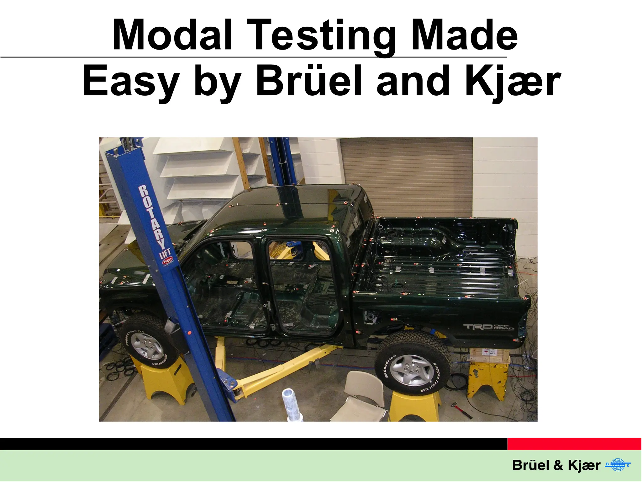
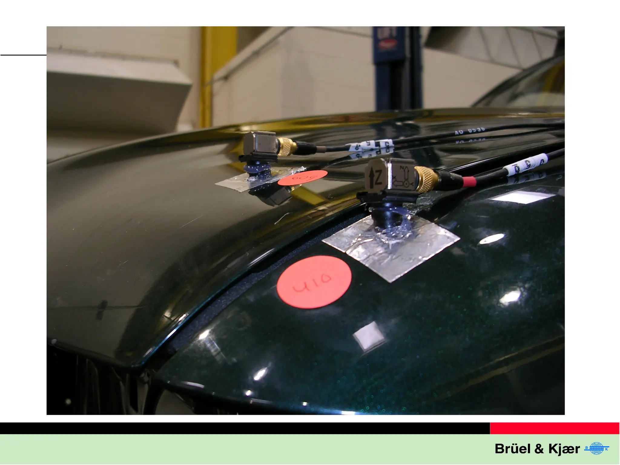
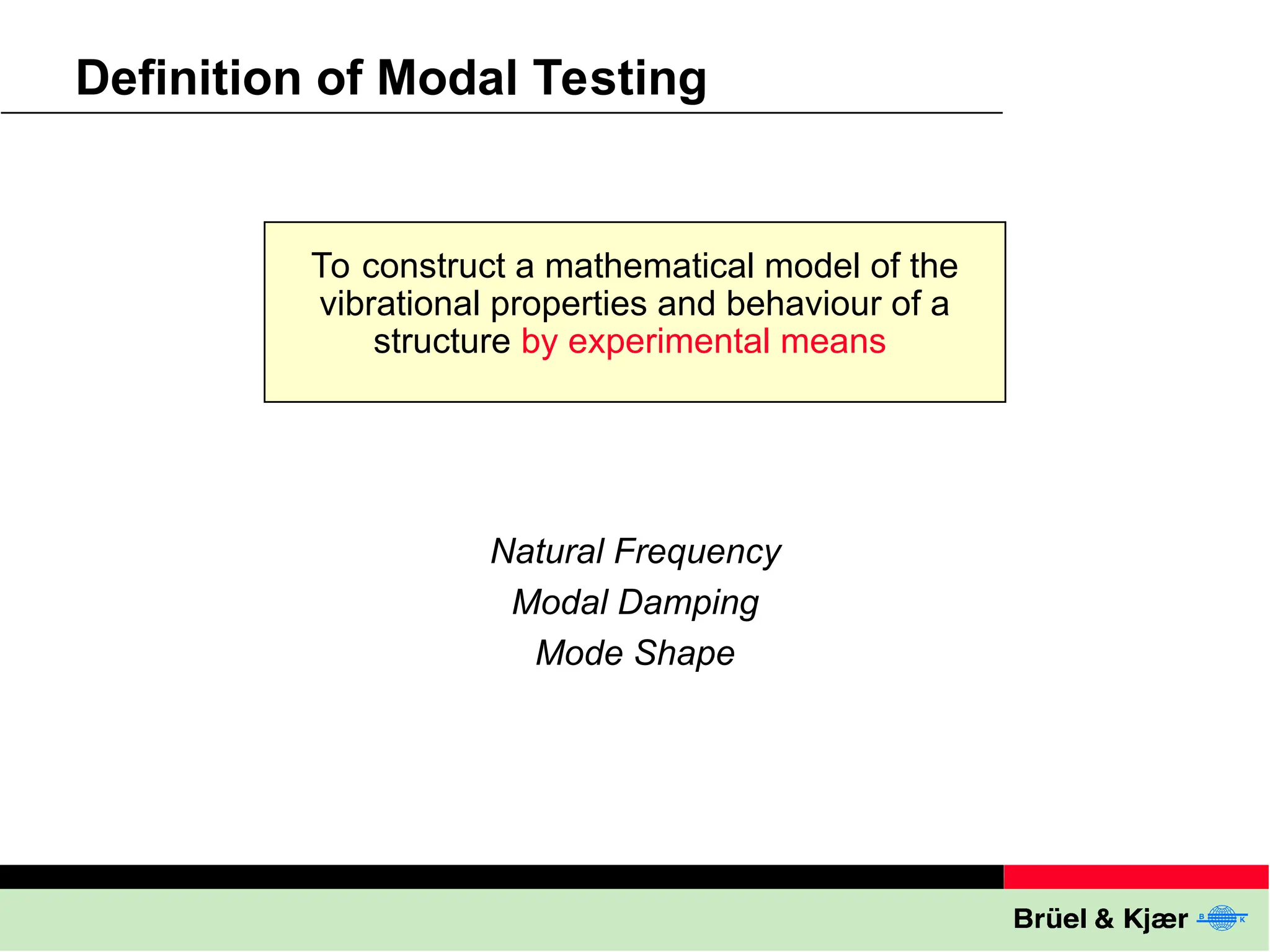
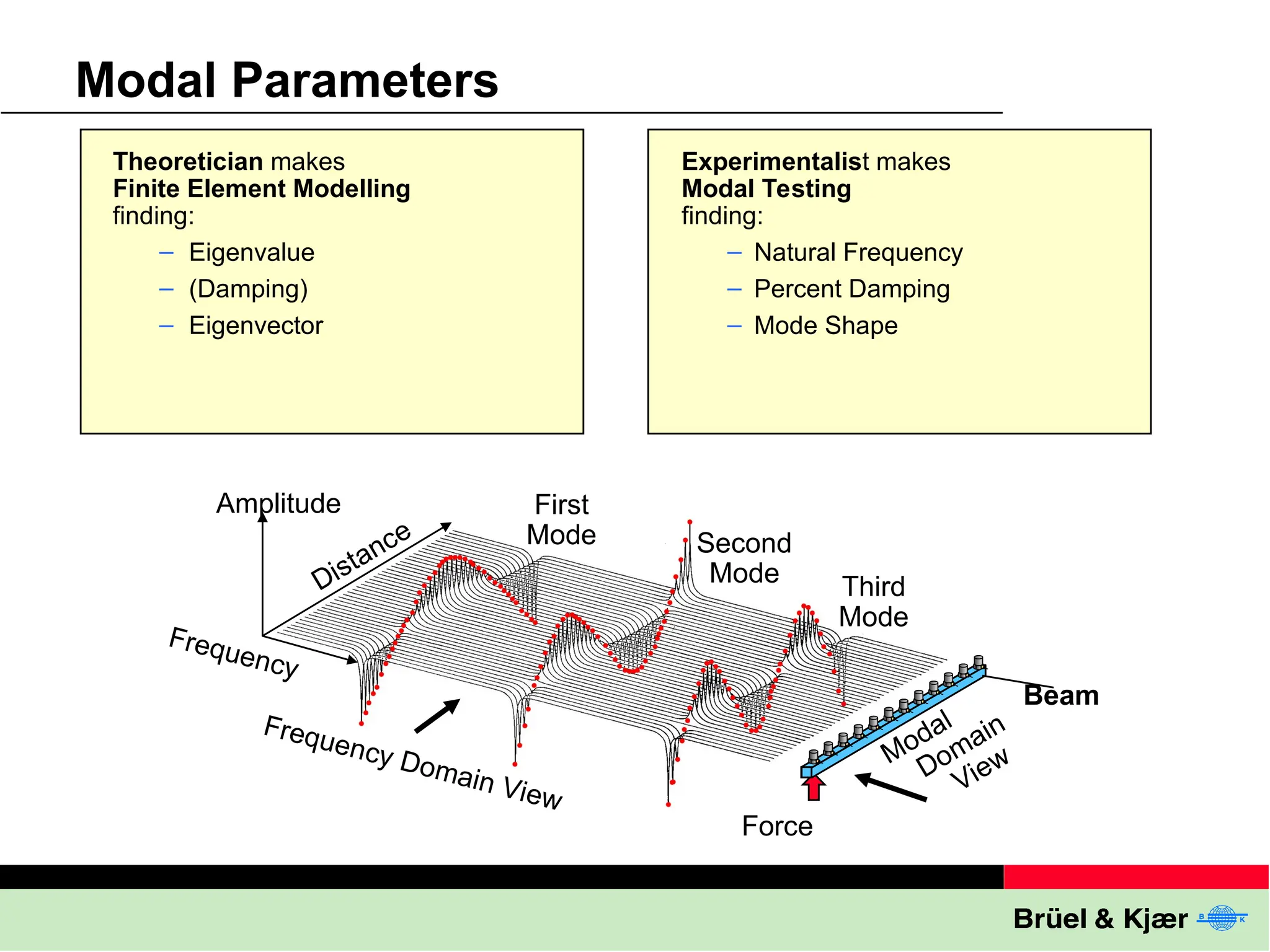
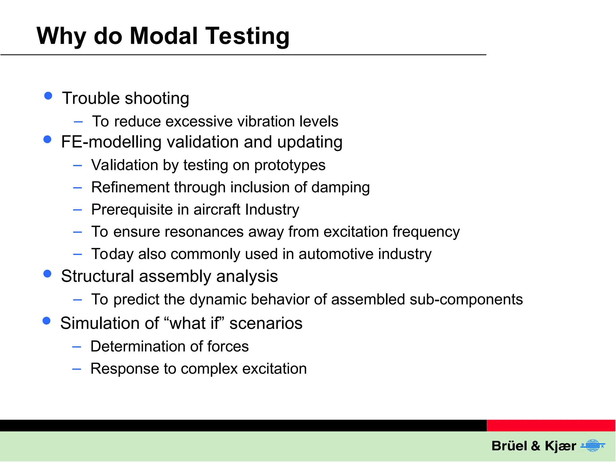
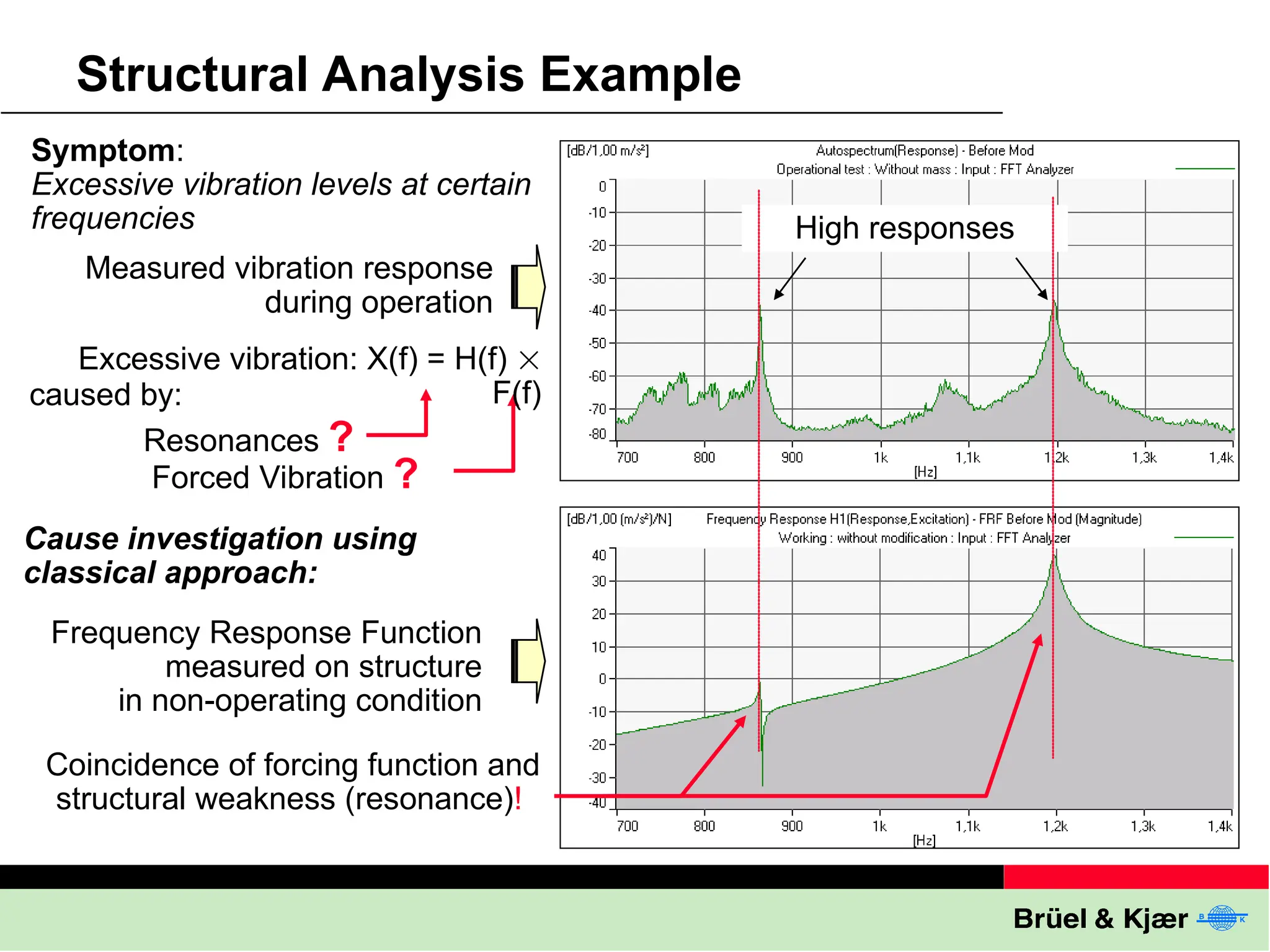
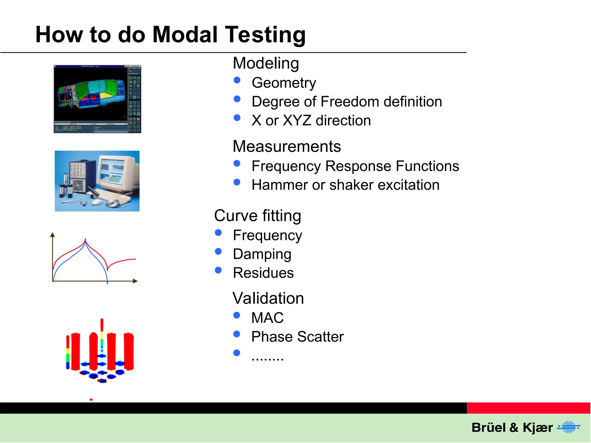
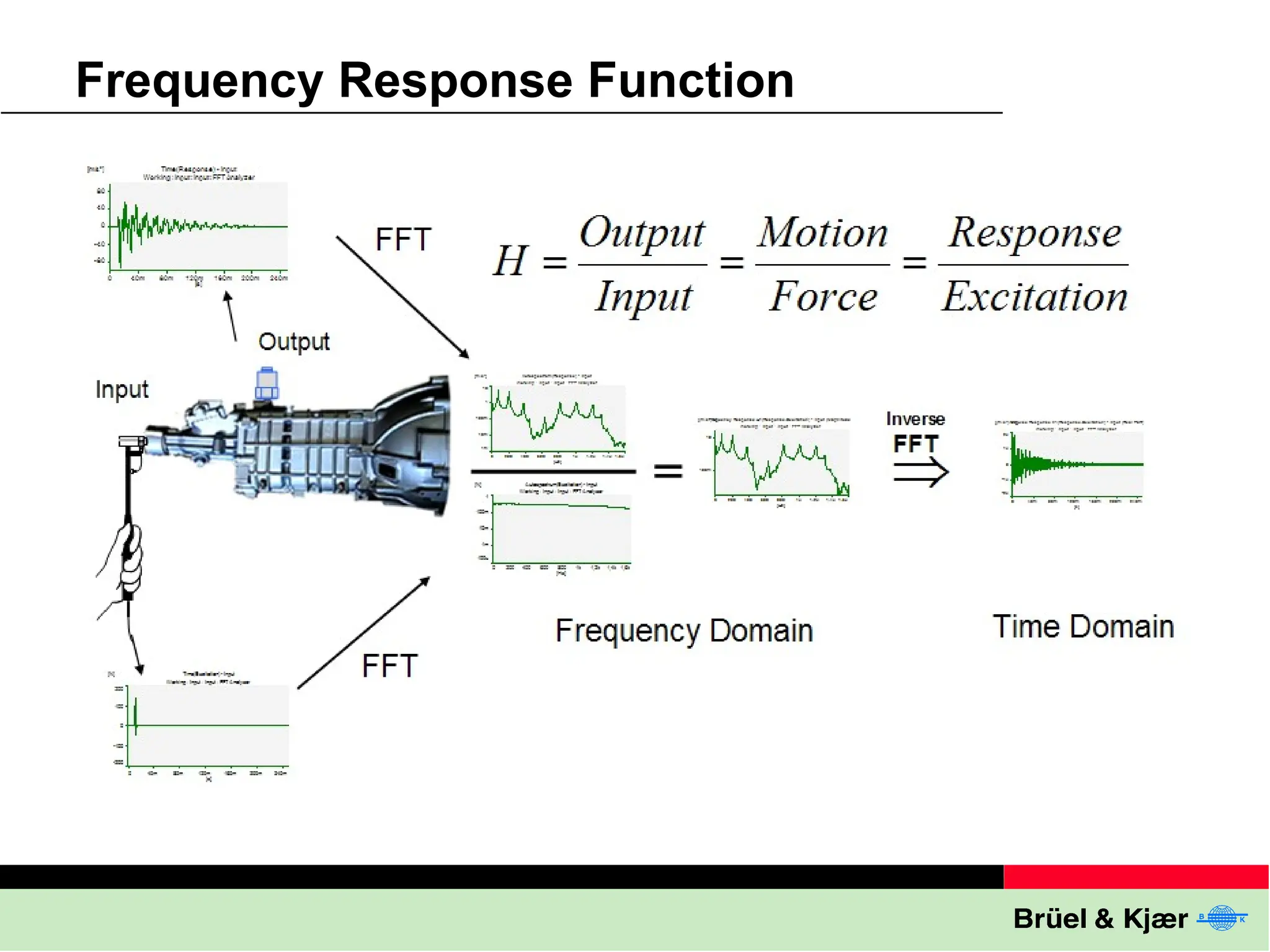
Modal Testing Made
Easy by Brüel and Kjær
Modal Testing
Why
How
Brüel & Kjær Solution
What
Definition of Modal Testing
To construct a mathematical model of the
vibrational properties and behaviour of a
structure by experimental means
Natural Frequency
Modal Damping
Mode Shape
Modal Parameters
Theoretician makes
Finite Element Modelling
finding:
– Eigenvalue
– (Damping)
– Eigenvector
Experimentalist makes
Modal Testing
finding:
– Natural Frequency
– Percent Damping
– Mode Shape
Frequency
Distance
Amplitude
Frequency Domain View
Modal
Domain
View
First
Mode Second
Mode Third
Mode
Force
Beam
Modal Testing
What
How
Brüel & Kjær Solution
Why
Why do Modal Testing
 Trouble shooting
– To reduce excessive vibration levels
 FE-modelling validation and updating
– Validation by testing on prototypes
– Refinement through inclusion of damping
– Prerequisite in aircraft Industry
– To ensure resonances away from excitation frequency
– Today also commonly used in automotive industry
 Structural assembly analysis
– To predict the dynamic behavior of assembled sub-components
 Simulation of “what if” scenarios
– Determination of forces
– Response to complex excitation
Static vs. Dynamic
Structural Analysis Example
High responses
Symptom:
Excessive vibration levels at certain
frequencies
Resonances ?
Forced Vibration ?
Excessive vibration: X(f) = H(f) 
F(f)
caused by:
Measured vibration response
during operation
Cause investigation using
classical approach:
Coincidence of forcing function and
structural weakness (resonance)!
Frequency Response Function
measured on structure
in non-operating condition
2. Structural Dynamics Modification
3. Forced Response Simulation
Solving the Problem
High response Low response
Previous
response
1. Experimental modal model
constructed and validated
4. Implementing proposed
mechanical changes on
physical structure
How to change dynamic properties
to minimise resonance problems:
– change mass
– change stiffness
– introduce tuned absorber
– make sensitivity analysis
How will a structure behave when
one or more forces are applied?
What
Why
Brüel & Kjær Solution
Modal Testing
How
How to do Modal Testing
Modeling
 Geometry
 Degree of Freedom definition
 X or XYZ direction
Measurements
 Frequency Response Functions
 Hammer or shaker excitation
Curve fitting
 Frequency
 Damping
 Residues
Validation
 MAC
 Phase Scatter
 ........
Frequency Response Function
Modal Testing
What
Why
How
Brüel & Kjær Solution
Example Hammer Set-up
4-channel Portable PULSE, 3560
Multi-analyzer system
Noise and vibration
analysis software
Modal Test Consultant
Brüel & Kjær
Pulse Reflex
Modal Solution
Software,
maintenance
and update
agreement
Adhesive
Mounting
Kit
Swivel
base clips
100 pcs
Modal test made easy with Bruel & Kjaer.ppt

Modal test made easy with Bruel & Kjaer.ppt

  • 1.
    Modal Testing Made Easyby Brüel and Kjær
  • 3.
    Modal Testing Why How Brüel &Kjær Solution What
  • 4.
    Definition of ModalTesting To construct a mathematical model of the vibrational properties and behaviour of a structure by experimental means Natural Frequency Modal Damping Mode Shape
  • 5.
    Modal Parameters Theoretician makes FiniteElement Modelling finding: – Eigenvalue – (Damping) – Eigenvector Experimentalist makes Modal Testing finding: – Natural Frequency – Percent Damping – Mode Shape Frequency Distance Amplitude Frequency Domain View Modal Domain View First Mode Second Mode Third Mode Force Beam
  • 6.
  • 7.
    Why do ModalTesting  Trouble shooting – To reduce excessive vibration levels  FE-modelling validation and updating – Validation by testing on prototypes – Refinement through inclusion of damping – Prerequisite in aircraft Industry – To ensure resonances away from excitation frequency – Today also commonly used in automotive industry  Structural assembly analysis – To predict the dynamic behavior of assembled sub-components  Simulation of “what if” scenarios – Determination of forces – Response to complex excitation
  • 8.
  • 9.
    Structural Analysis Example Highresponses Symptom: Excessive vibration levels at certain frequencies Resonances ? Forced Vibration ? Excessive vibration: X(f) = H(f)  F(f) caused by: Measured vibration response during operation Cause investigation using classical approach: Coincidence of forcing function and structural weakness (resonance)! Frequency Response Function measured on structure in non-operating condition
  • 10.
    2. Structural DynamicsModification 3. Forced Response Simulation Solving the Problem High response Low response Previous response 1. Experimental modal model constructed and validated 4. Implementing proposed mechanical changes on physical structure How to change dynamic properties to minimise resonance problems: – change mass – change stiffness – introduce tuned absorber – make sensitivity analysis How will a structure behave when one or more forces are applied?
  • 11.
    What Why Brüel & KjærSolution Modal Testing How
  • 12.
    How to doModal Testing Modeling  Geometry  Degree of Freedom definition  X or XYZ direction Measurements  Frequency Response Functions  Hammer or shaker excitation Curve fitting  Frequency  Damping  Residues Validation  MAC  Phase Scatter  ........
  • 13.
  • 14.
  • 15.
    Example Hammer Set-up 4-channelPortable PULSE, 3560 Multi-analyzer system Noise and vibration analysis software Modal Test Consultant Brüel & Kjær Pulse Reflex Modal Solution Software, maintenance and update agreement Adhesive Mounting Kit Swivel base clips 100 pcs

Editor's Notes

  • #5 Once the design of a structure has been accepted, a prototype is produced to carry out modal tests to verify the dynamic parameters – natural frequencies, modal damping and residues which are the components of the mode shapes – predicted for the design. The experimentally determined parameters which rarely agree with those predicted, can nevertheless be used to make a mathematical model for structural dynamic modifications and for investigating the dynamic behaviour of the structure.
  • #6 To understand what modal parameters are, consider a simple free-free beam excited at one end by a random force. If the imaginary part of the response (i.e. motion, be it acceleration, velocity or displacement) is measured at different points on the beam as a function of frequency, a set of curves would be obtained as shown in the 3D plot in the diagram. The first three natural (resonance) frequencies, where the amplitudes start building up, are clearly seen along the frequency axis. By connecting the peaks at each of the natural frequencies the corresponding mode shapes can be traced out. Furthermore, if the 3 dB bandwidths at each of the resonances are determined, the loss factor can be calculated which gives the amount of modal damping for each of the modes. (In practice these are determined through curve fitting the frequency response curves) Using structural mechanics (FE method), the theoretician can calculate system stiffnesses and masses and with this eigenvalues and eigenvectors that are simply the undamped natural frequencies and the corresponding undamped mode shapes, because damping is generally not taken into account in the design at this stage. Although these values can be mathematically related to the measured values, they rarely agree in practice. From the 3D plot it can be seen that information about the dynamic properties of the structure lies at the natural frequencies and in their vicinity. Thus by determining the 3 above mentioned parameters experimentally for the first 10 modes, for example, a mathematical model can be built up in a computer.
  • #7 With the advent of the aircraft industry, it was not only necessary to test structures for their static load capabilities, but also to investigate their behaviour under dynamic loading to verify the design parameters of the structures. The field of Structural Dynamic Testing as it was then called, has developed both theoretically and experimentally over the years, and is widely used today in all advanced industries under the terminology – Modal Analysis and Modal Testing. The purpose of this lecture is to describe what is Modal Testing, explain why we do Modal Testing and illustrate how Modal Testing is carried out in practice. Finally, the features incorporated in Brüel & Kjær instrumentation to facilitate Modal Testing will be highlighted.
  • #11 The pictures and the video shows the spectacular collapse of the Tacoma Narrows Bridge on the morning of Nov. 7, 1940. The bridge was an unusually light design, and, as engineers discovered, peculiarly sensitive to high winds. Rather than resist them, as most bridges do, the Tacoma Narrows tended to sway and vibrate. On November 7, in a 40-mile-per-hour wind, the center span began to sway, then twist. The combined force of the winds and internal stress was too great for the bridge, and it self-destructed. No one was killed, as the bridge had been closed because of previous swaying. This is one of the best-known and most closely studied engineering failures, thanks in large part to the film and photographs that recorded the collapse. To read more see: http://www.nwrain.com/~newtsuit/recoveries/narrows/gg.htm http://www.enm.bris.ac.uk/research/nonlinear/tacoma/tacoma.html Youtube search “Aeroelastic Flutter” http://www.youtube.com/watch?v=qpJBvQXQC2M Youtube search “Tacoma Narrow Bridge Collapse” http://www.youtube.com/watch?v=j-zczJXSxnw Airbus A380 Flutter Test http://www.youtube.com/watch?v=s3-g9B6Fgjs NASA videos: Aeroelastic Phenomena and Related Research - Part 1 http://www.youtube.com/watch?v=rb3JHY_-ia4 Aeroelastic Phenomena and Related Research - Part 2 http://www.youtube.com/watch?v=jW8I2hX4GSs&NR=1
  • #12 One of the most widely used applications of modal testing is in the field of trouble shooting. The figure on top is the frequency response function of a plate when excited at a point using a hammer and the response measured at some other relevant point. The fact that the plate has two resonances as can be seen in the diagram is not a problem in itself. The problem only arises, if the plate is excited at a resonance frequency during operation, for example, at 1.2 kHz. In this case the amplitude at this point would be rather high as shown in the bottom diagram. To avoid this problem, one can either change the operation of the machine such that the excitation frequency is moved away from the resonance frequency, or modify the plate such that its resonance frequency is moved further up or down in the frequency range.
  • #13 In the example of the plate, the resonance frequency was moved down to approximately 1.15 kHz by mounting an additional mass on the plate. It can be seen from the bottom diagram that the response of the plate under excitation is therefore now significantly reduced at 1.2 kHz. Similarly, the resonance frequencies can be moved to higher frequencies by attaching a stiffener to a structure. In some cases moving the frequencies may not result in enough attenuation, and the only solution left would be to add a tuned absorber. To avoid such trial and error methods of adding and removing masses and stiffeners, a more professional approach can be implemented using the Structural Dynamics Modification’ program. This program utilises the mathematical model of the structure, synthesised from the measured modal parameters described previously. This software can not only predict the response of the structure when such changes are made, but could also be used to indicate optimum positions on the structure, where such modifications should be implemented. The ‘Forced Response Simulation’ software makes use of the mathematical model to predict the response of the structure at any point when excited by a variety of forces. Thus investigating potential design changes by computer modelling can dramatically reduce the time and cost of understanding and solving troublesome vibration problems.
  • #17 Abstract This etc.