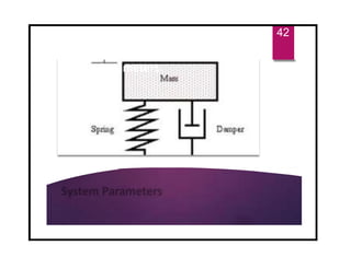
The document discusses the basics of vibrations in rotating machinery, emphasizing their importance in assessing machine condition and diagnosing faults. It outlines causes of vibrations, measurement methods, relationship between displacement, velocity, and acceleration, and key concepts like resonance and natural frequency. Additionally, it addresses factors affecting vibration behavior such as mass, stiffness, and damping.

![Phase measurements methods
Photoelectric or laser probes. [Absolute Phase]
Strobe light. [Obsolete]
Dual channel analyzer. [Relative Phase]
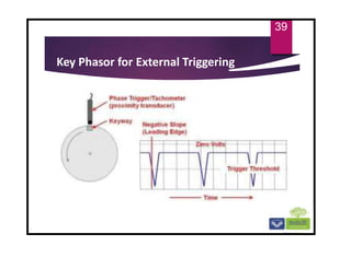
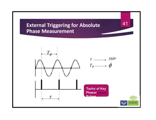
Key phasor. [Absolute Phase for Turbomachinery]
38](https://image.slidesharecdn.com/chapter1-240702110720-c03b3043/85/chapter-1basic-of-rotating-machinery-vibration-pptx-38-320.jpg)


![Vibration_and_Its_Causes[1] Vibrations.pdf](https://cdn.slidesharecdn.com/ss_thumbnails/vibrationanditscauses1-241125115821-611dbbe3-thumbnail.jpg?width=640&height=640&fit=bounds)


