The document summarizes the process of AMR call establishment between a UE and core network. Key steps include:
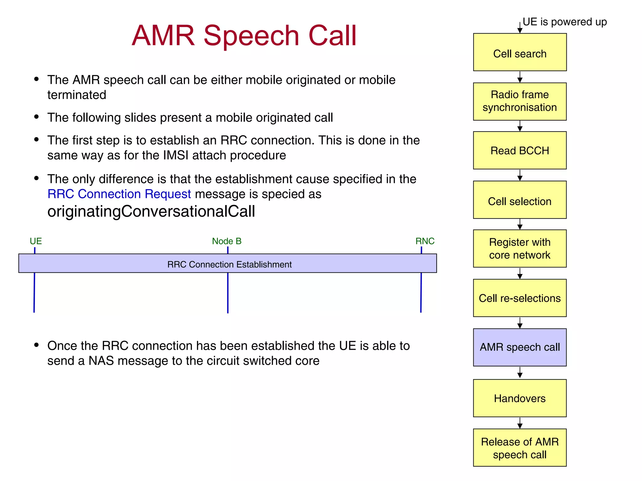
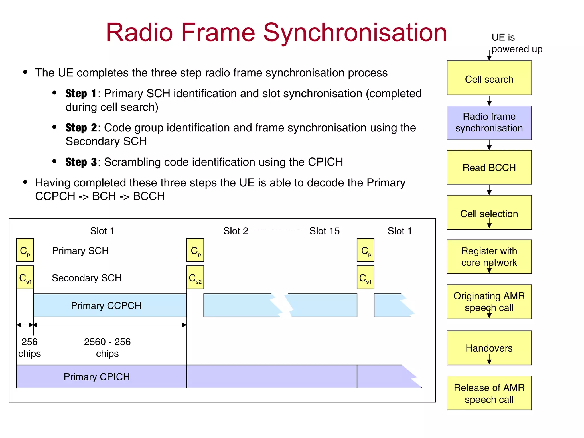
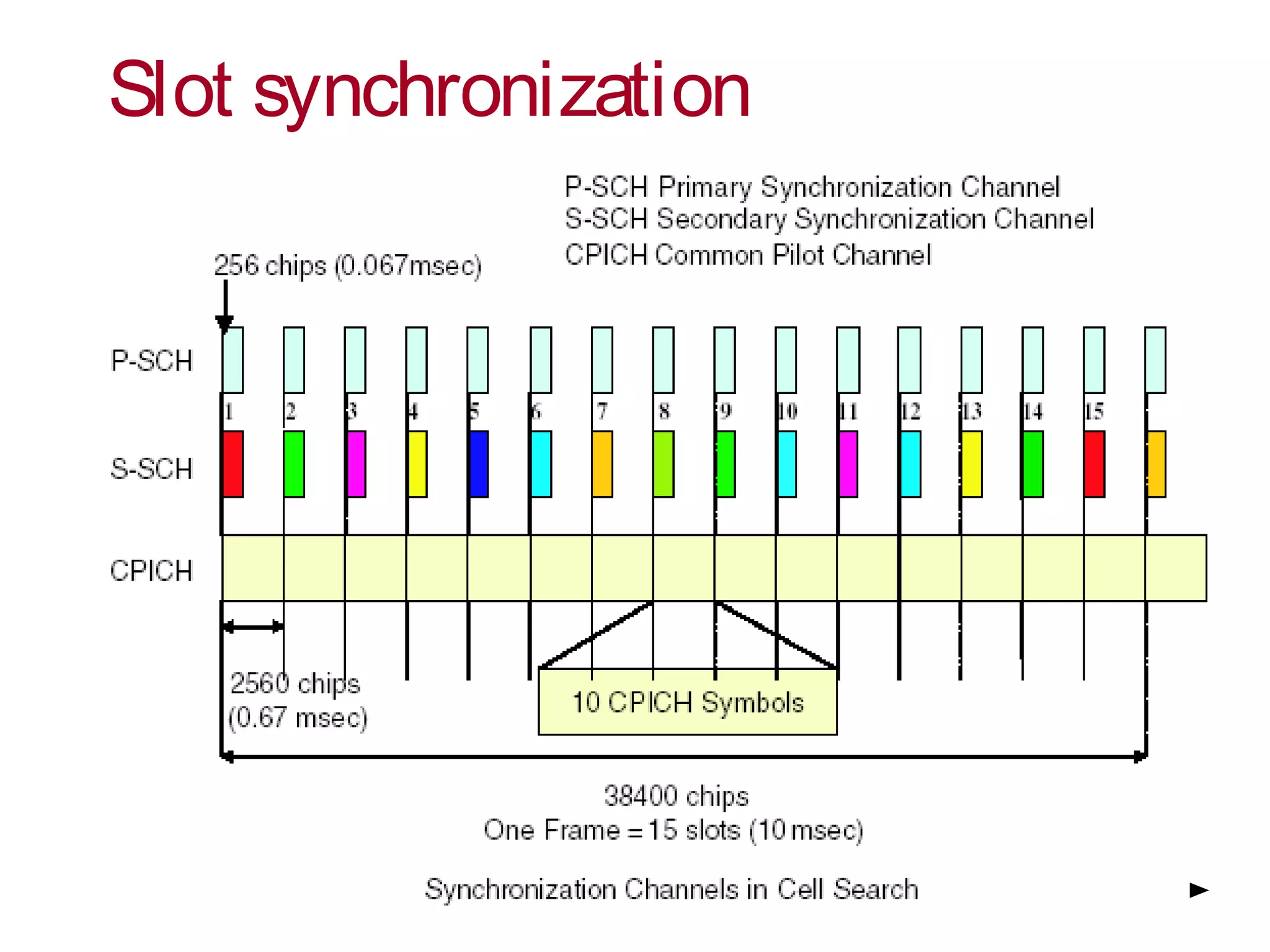
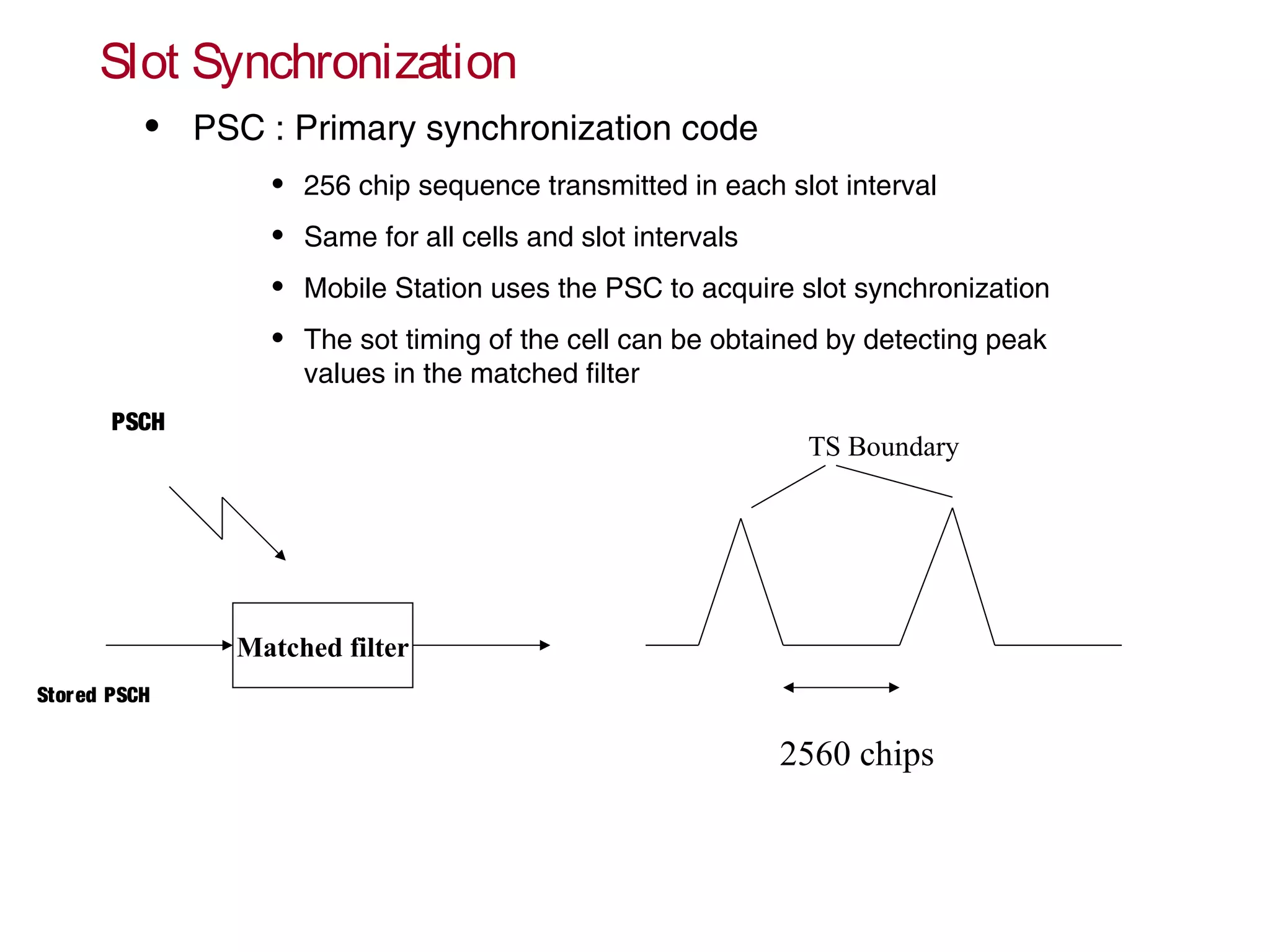
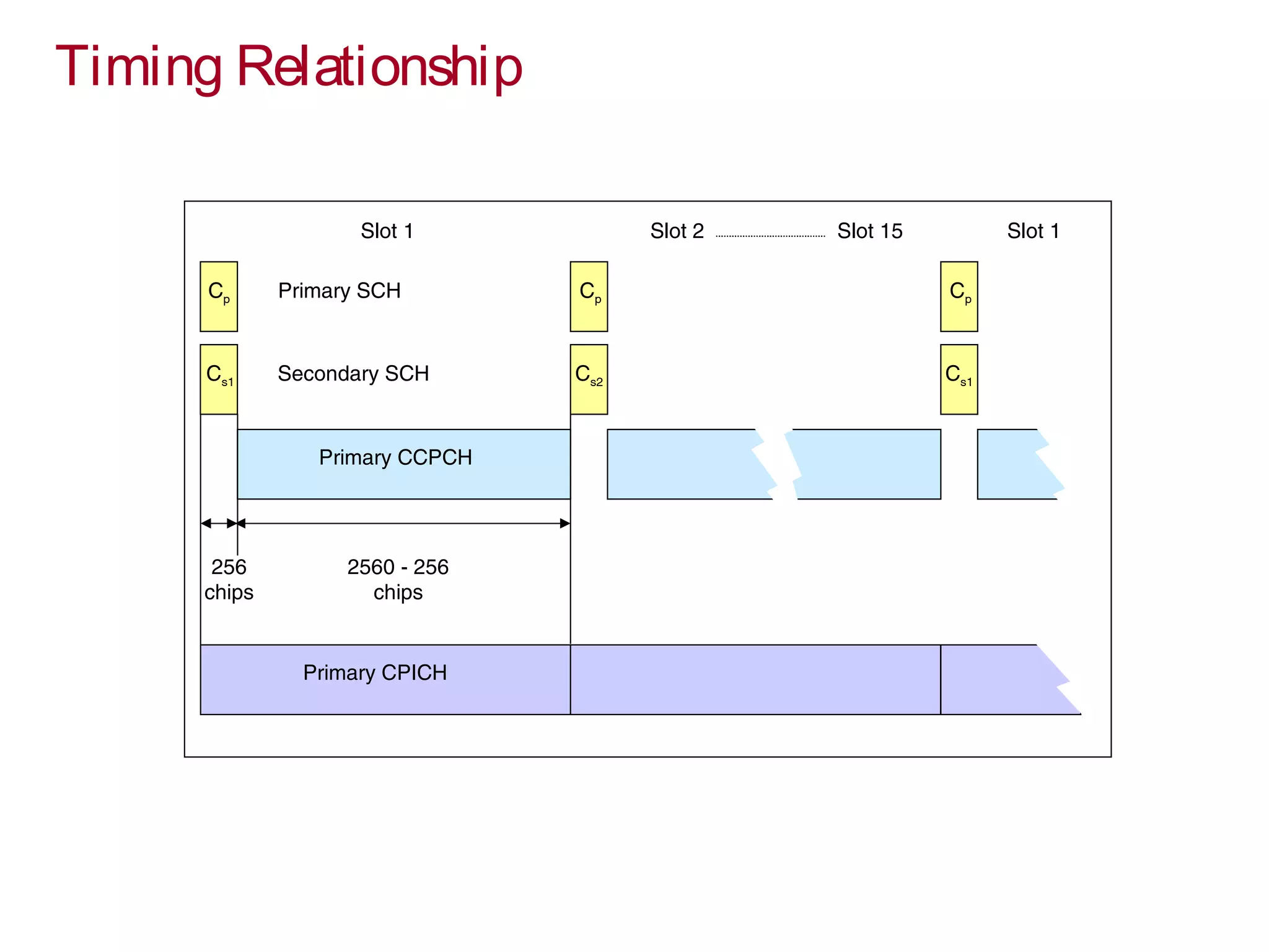
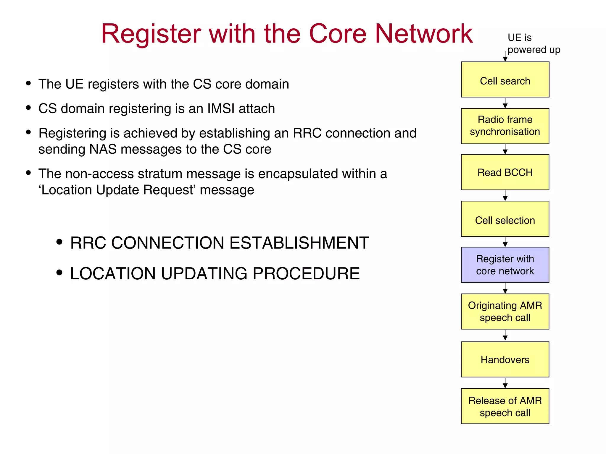
1. The UE searches for cells, synchronizes with the radio frame, and reads system information from the BCCH logical channel.
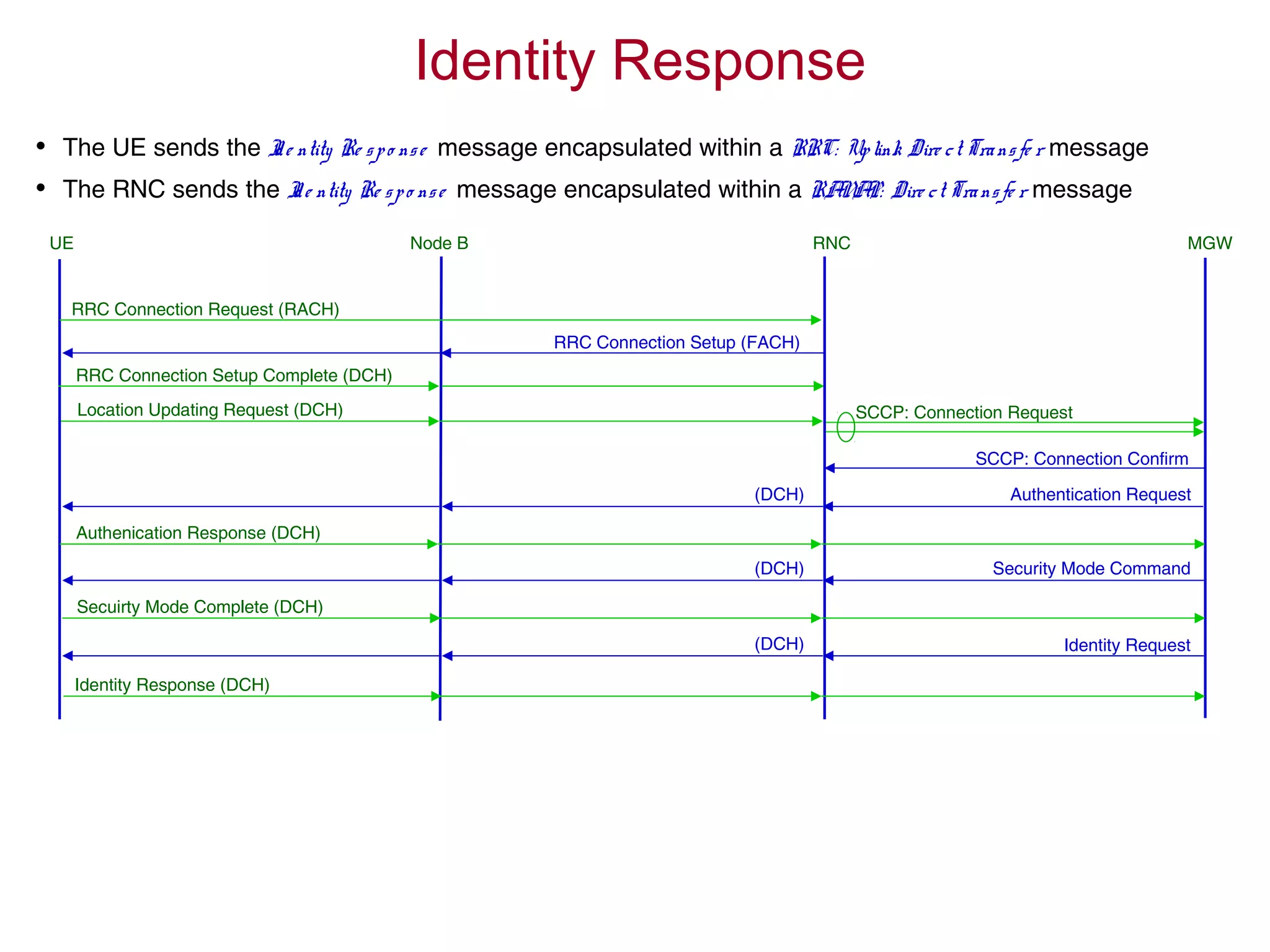
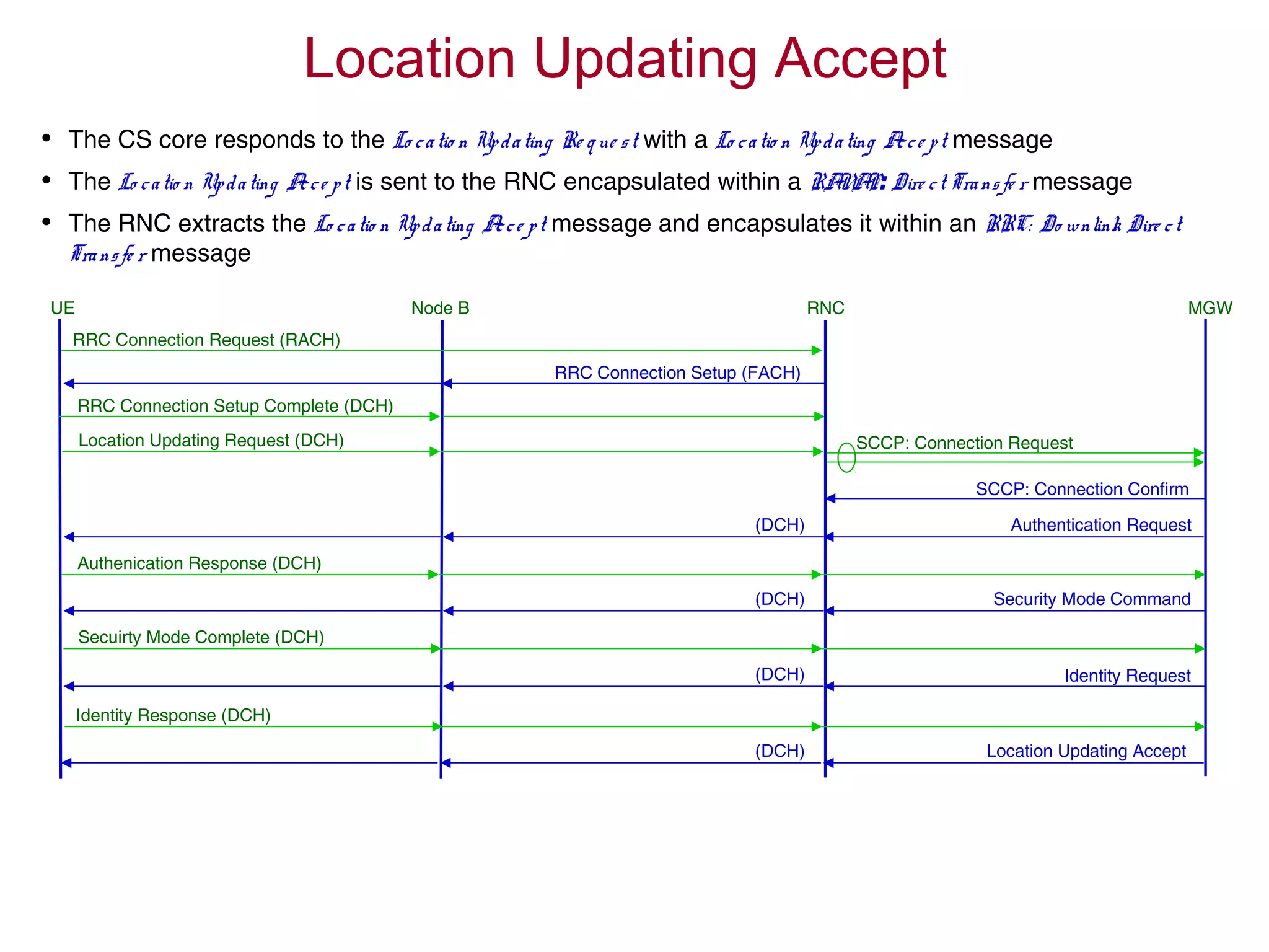
2. If the cell passes the UE's cell selection criteria, it establishes an RRC connection and registers with the core network.
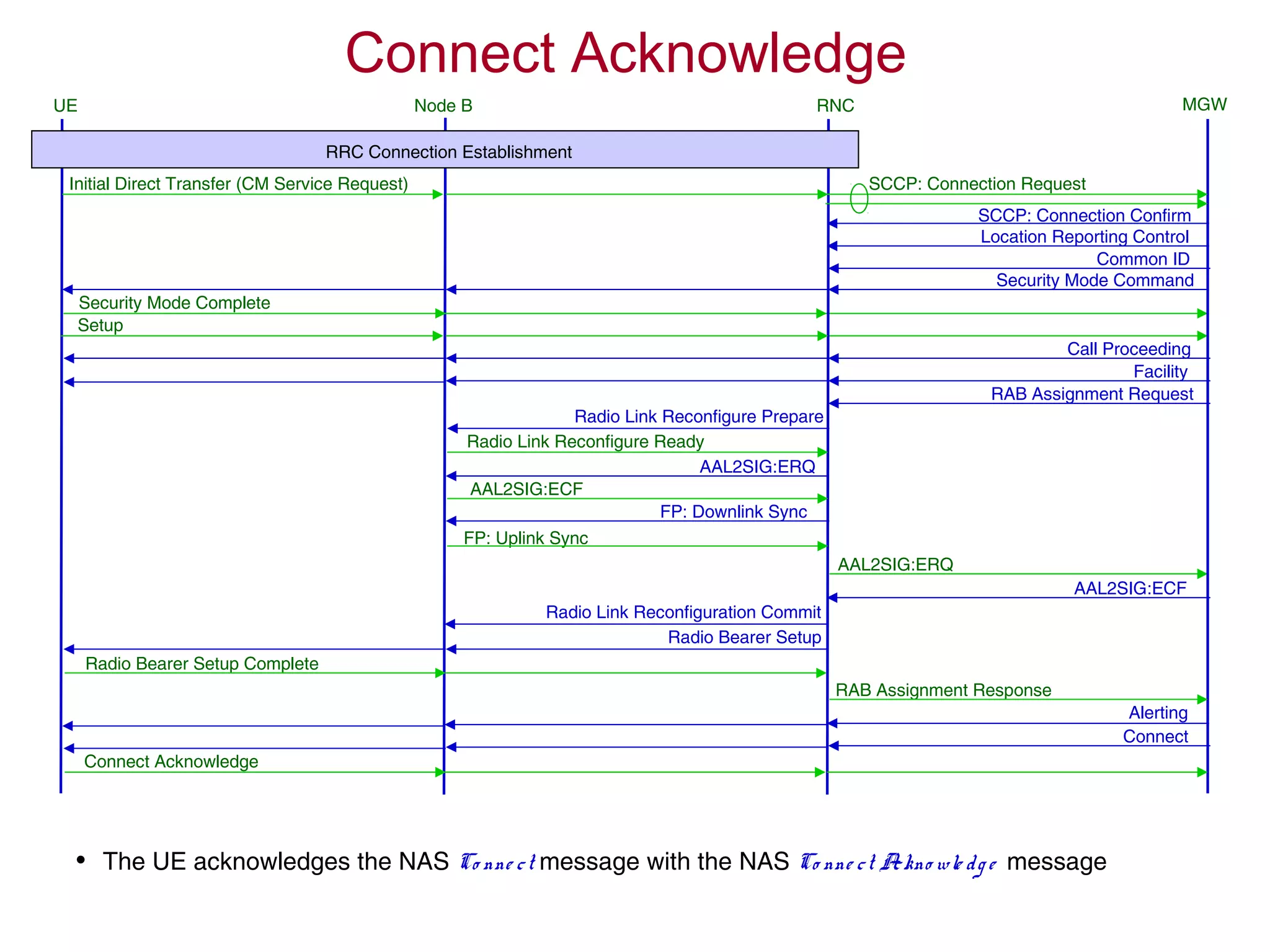
3. Having registered, the UE can originate an AMR speech call, which may involve handovers between cells as needed.
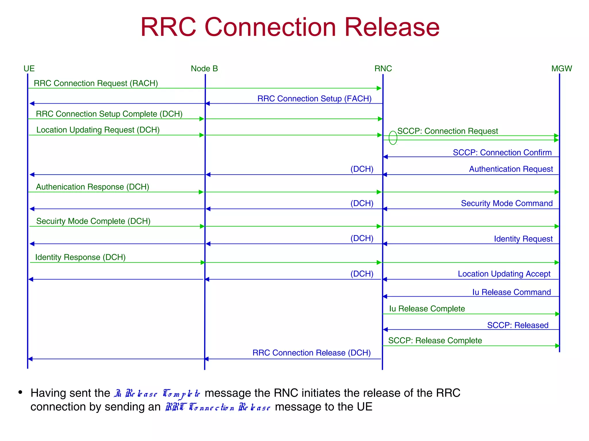
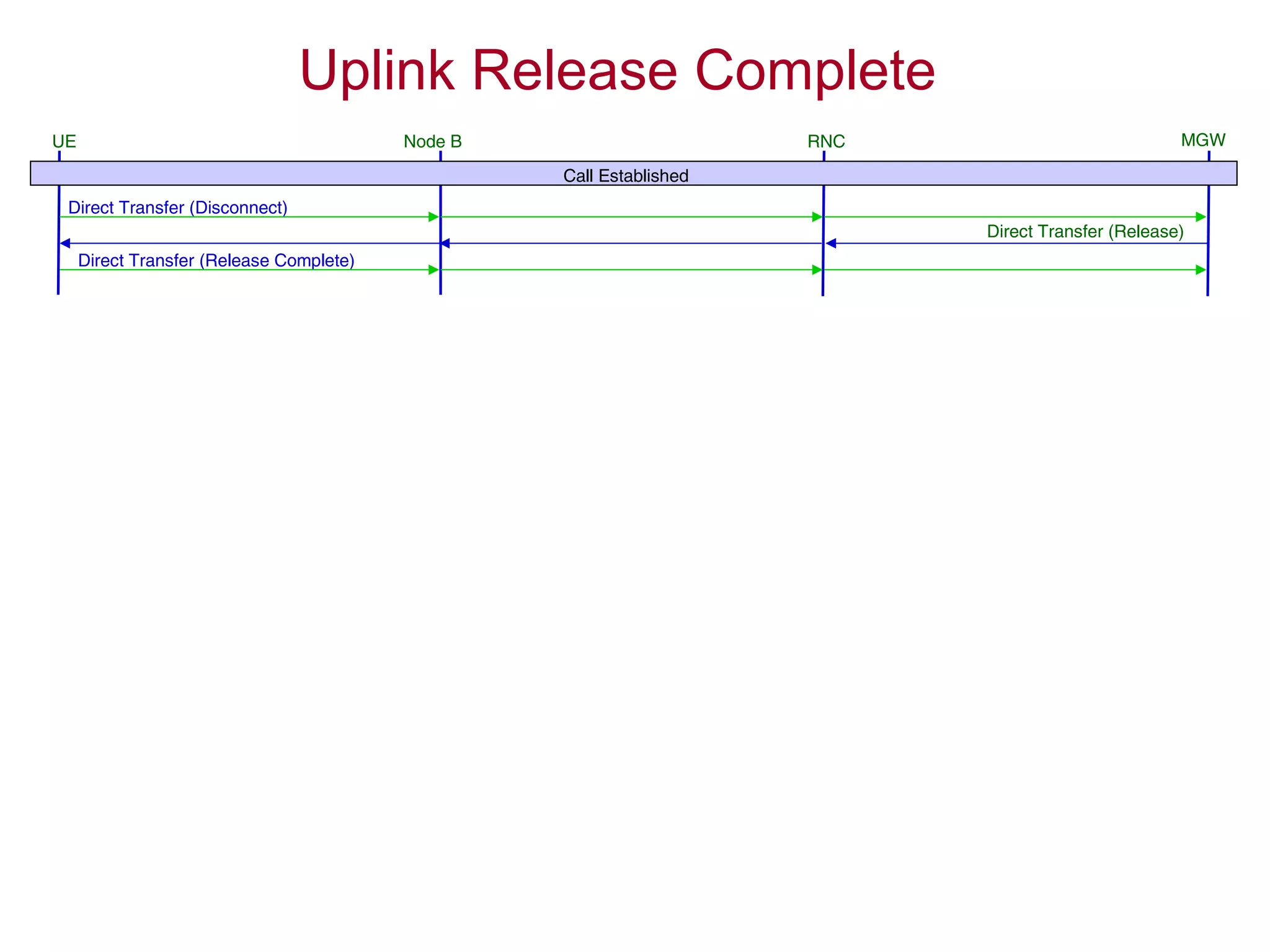
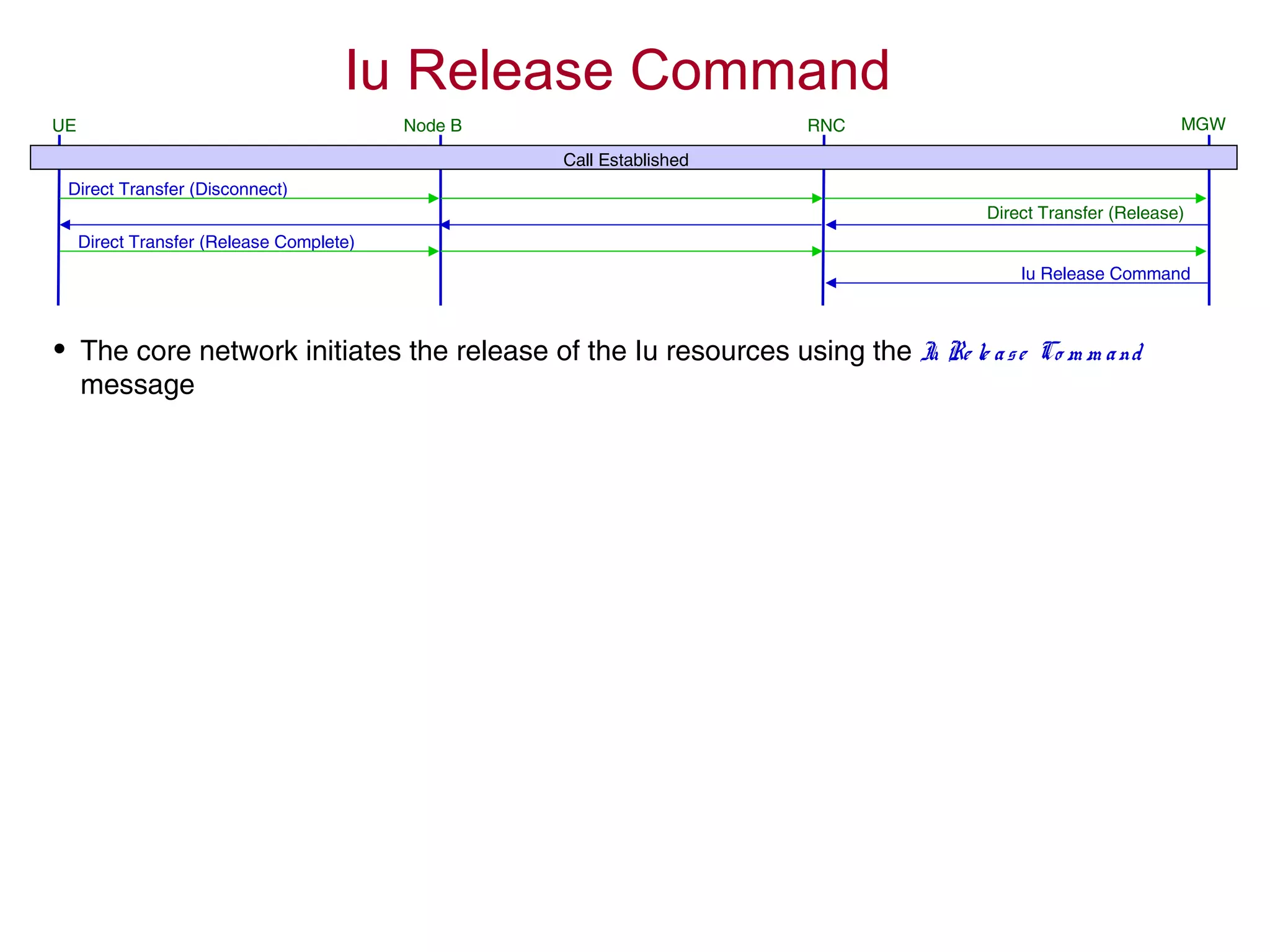
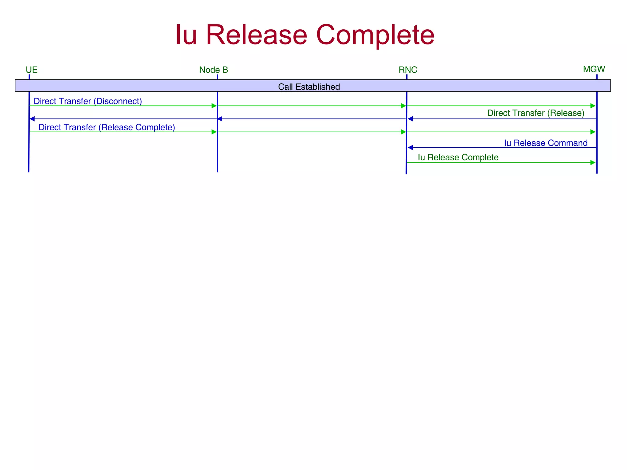
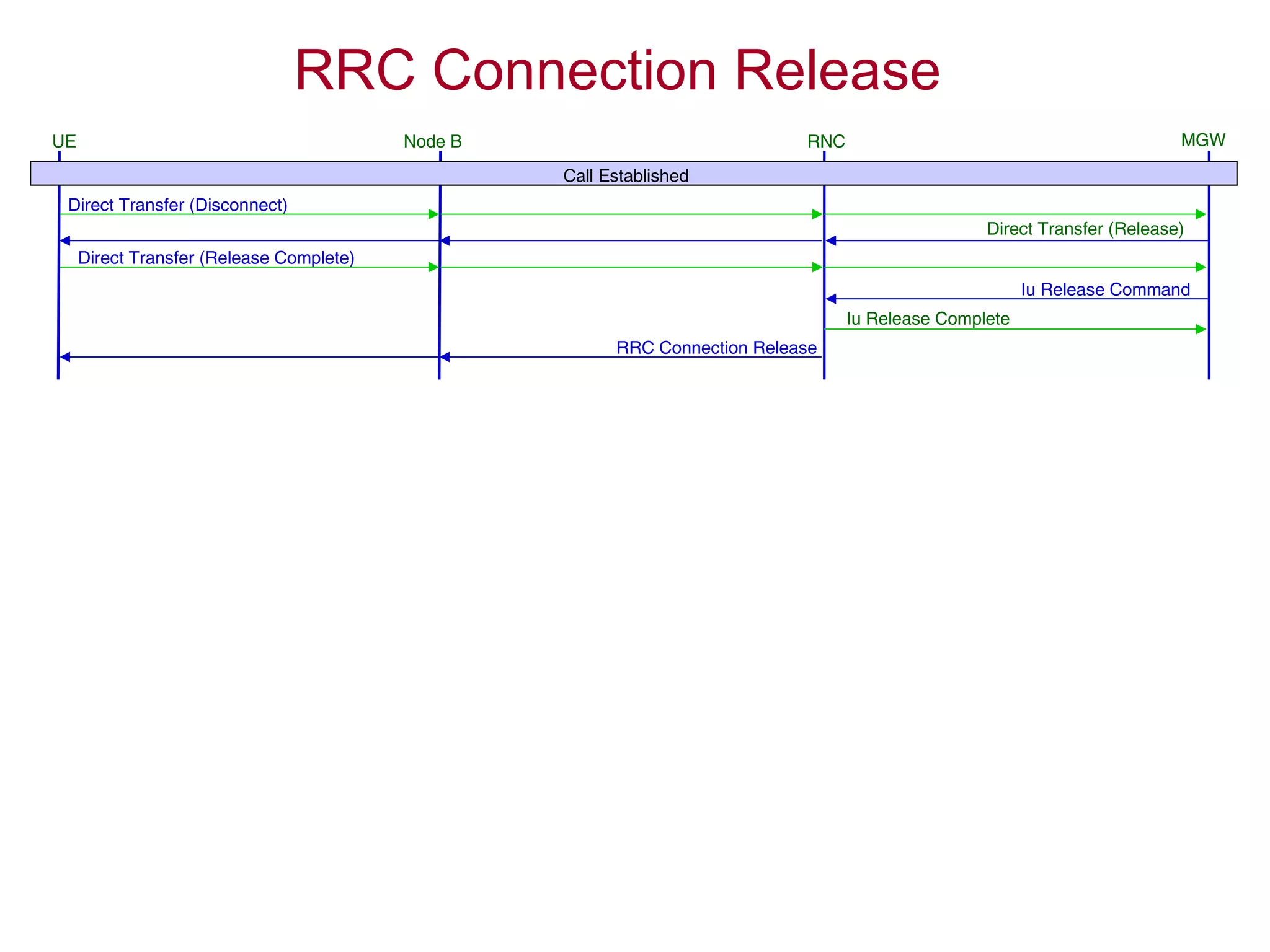
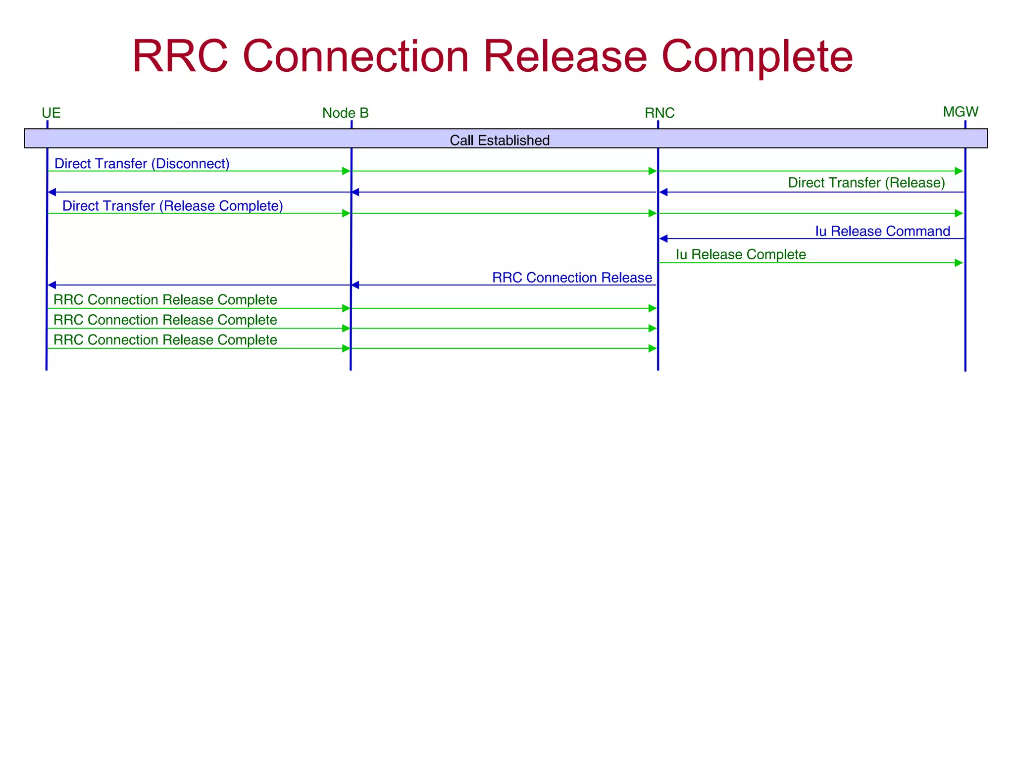
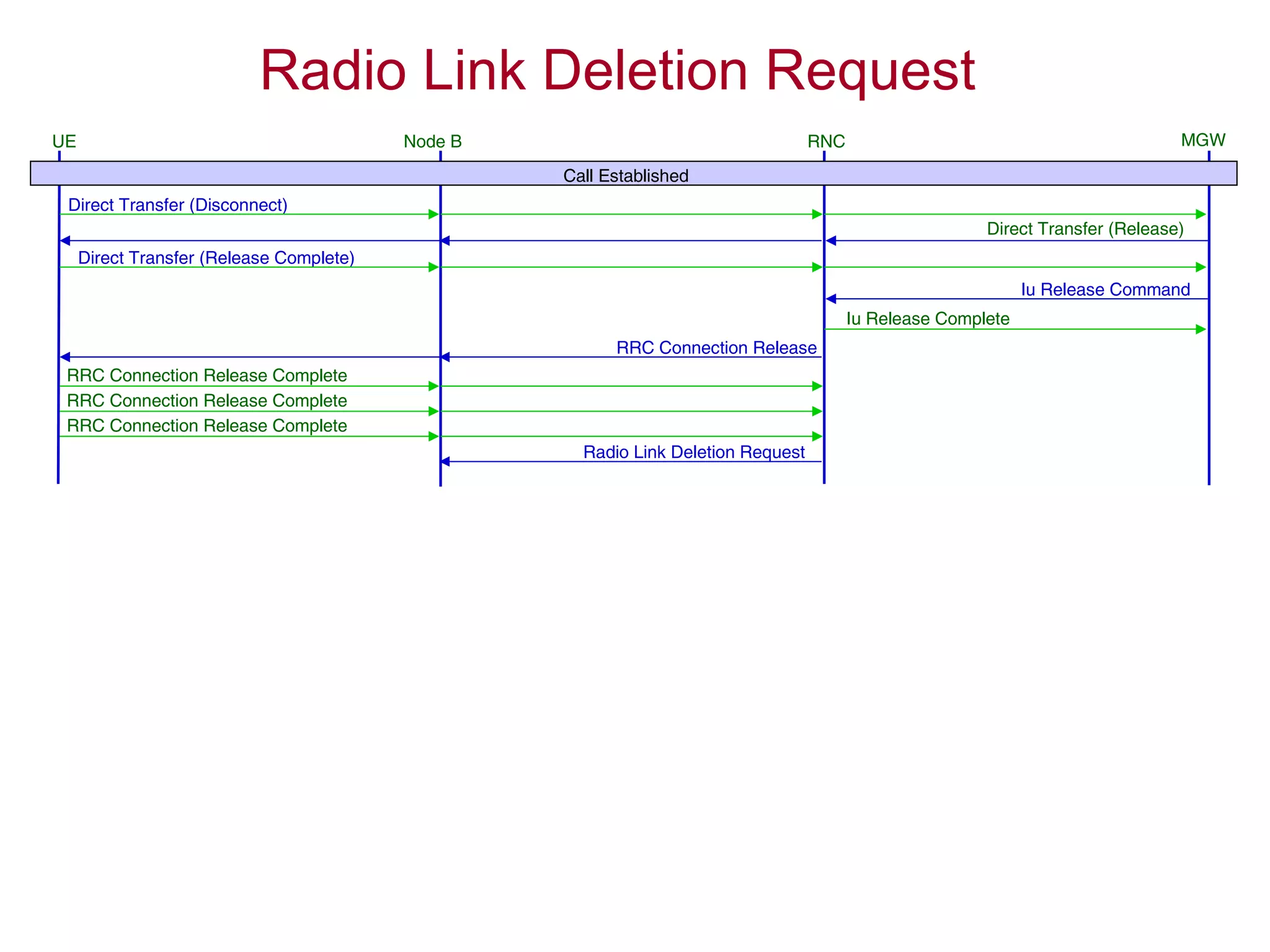
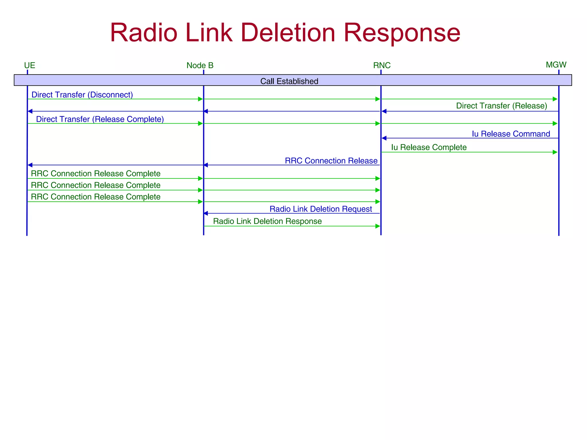
4. The AMR call is eventually released, and the UE returns to the idle mode state.


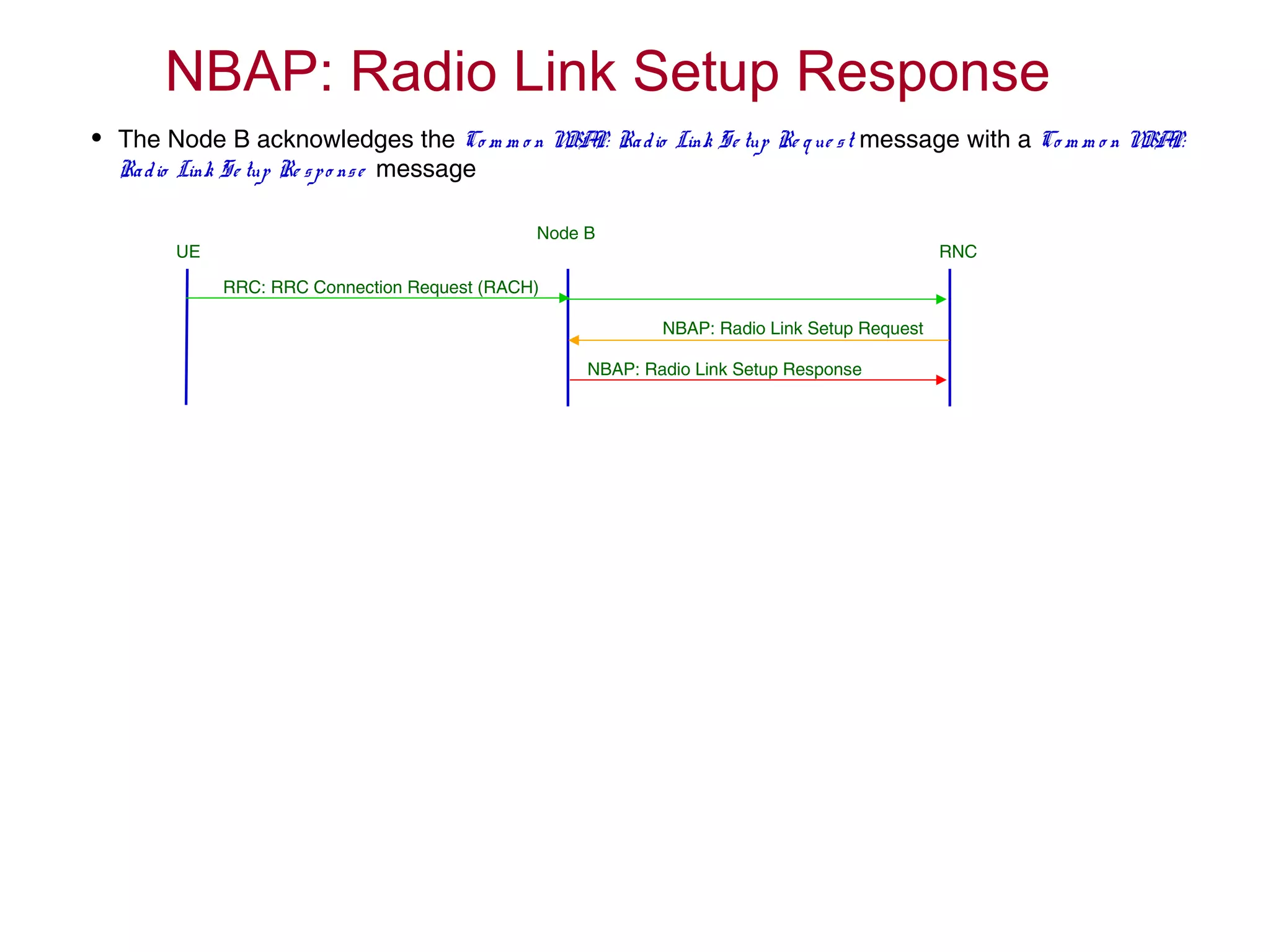
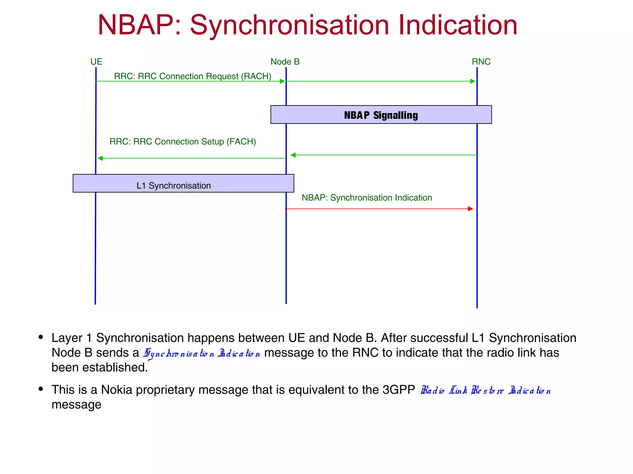
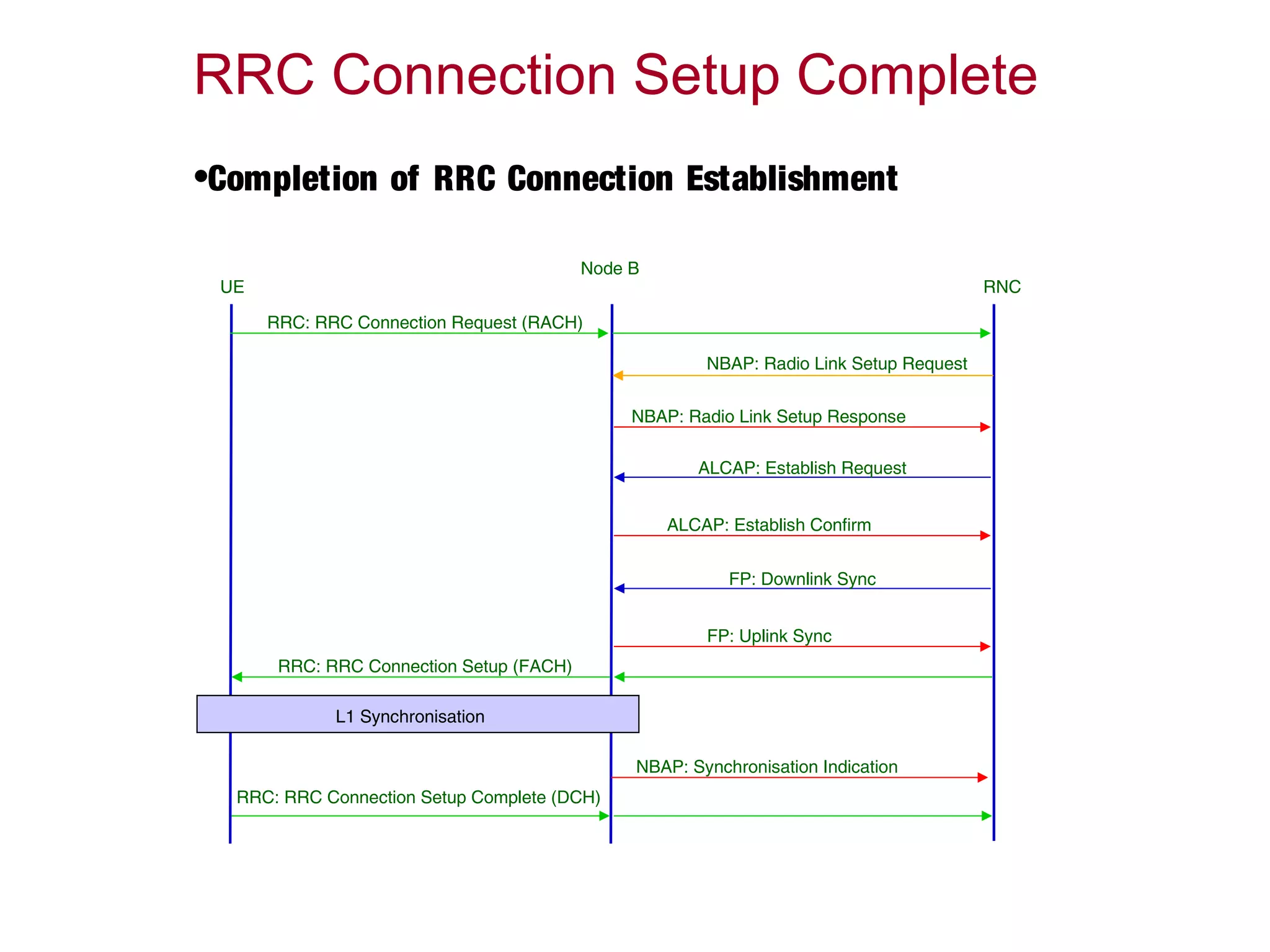
![RRC Connection Establishment
Node BUE RNC
[RACH] RRC Connection Request
[DCH] RRC Connection Setup Complete
[FACH] RRC Connection Setup
Radio Link Setup
L1 Synchronisation
accept
ed
[RACH] RRC Connection Request
[FACH] RRC Connection Reject
UE RNC
rejecte
d](https://image.slidesharecdn.com/mocscallflow-170308115225/75/Mo-cs-call_flow-25-2048.jpg)