SlideShare a Scribd company logo
1 of 7
Download to read offline
The Mite Cycle, with its builder, is shown above. A 
small one-cylinder engine provides the motive power. 
MITE CYCLE 
You'll need only an "A" ration 
to run this midget motorcycle. 
by R. G. Fisher 
This little motorcycle has been designed 
. to operate on wartime rations! Its 
construction is simple and light, but it is 
surprisingly practical and will carry a 
250-lb. passenger without complaining. A 
5/8-h.p. engine whips it along at a 25-m.p.h. 
clip and as for gas consumption—one gallon 
for every 120 miles, and we doubt if there's 
another motorcycle that can do better than 
that. 
The Mite Cycle shown here was built by 
the author at a total cost of $50. It weighs 
85 lbs. and is powered by a Briggs and 
Stratton engine. All unnecessary frills 
were forgotten in its construction, and the 
only tools used were a small lathe, a hack 
saw and a welding torch. 
The frame, being the foundation of the 
project, should be built first. It is made 
of salvaged aircraft streamline tubing. 
2-1/2"x.035 wall, procurable from any air-port 
where small planes are repaired. 
These dimensions need not be adhered to 
exactly as a slightly larger or smaller 
tubing, or even a plain round tubing of 
1-1/8"x.035 wall, is satisfactory. After pro-curing 
the tubing make a full-size drawing 
of the frame on the shop floor and cut the 
pieces to the angles and lengths given, 
fitting them to the drawing as you go. 
After this is completed, build the two 
lower frame pieces. The base tube (11-1/2") 
is spotted to the forward tube going up 
to the fork neck and also to the rear tube 
going to the rear wheel hangers. Three 
spreaders are required and these are cut 
4" long from 1" o.d. .035 wall tubing; two 
of these are located bet-ween the lower 
frame sides and spotted into position as 
noted. The forward tubes are cut on the 
insides and bent together to form the V 
as shown in the bottom view, then welded. 
The upper rear tubes then are laid together 
and the third spreader is located 9-3/4" c.c. 
to the rear of the taper terminating point 
and welded into position. These tubes
«f» . 
The brake plate, shown in the diagram below, is in-stalled 
as above. Brake band is anchored at bottom. 
Slotted hole allows for adjustment of the drive belt. 
86 
are cut on the inside 1/2" forward of the 
spreader and bent to form the taper as shown 
in the top view. The forward tube is located 
and welded to the upper rear tubes. The 
lower frame now is set on the floor and the 
uprights located and spotted, the upper frame 
is placed into position on top and spotted, 
the frames are welded together at the rear 
wheel hangers and welding of the whole 
frame proceeds, work being carried forward 
and each section completed as it is reached. 
Rear wheel hangers are cut out of 3/16" cold 
rolled steel, cut long enough to extend inside 
the frame 1", and after joggling, they are in-serted 
and leveled. It is important that the 
hangers are level, otherwise the Cycle will 
not balance; when level they are brazed in 
position. Before attaching the fork neck, it 
is necessary to procure the standard bicycle 
bearings and races that are used in the neck. 
A piece of 1-1/2"X.125 wall tubing is cut 6-1/2" 
long and each end is bored to take the races. 
A line is drawn on the floor, the frame is 
placed level on the floor straddling the line 
and a plumb line is then dropped from the 
center line of the frame at the rear wheel 
hangers to the line. Another plumb bob is 
attached to the fork neck, and the fork neck is 
spotted into position while both bobs are on 
the line. Then the frame is brazed to the 
neck, making sure the frame is plumb. En-gine 
supports are made of 1-3/4"x3/4"x1/8" 
angle iron and located according to the engine 
used. Holes through these members for en-gine 
bolts should be slotted to permit adjust-
, A > - • • * » . 
ment of the belt. Foot rests are cut to 
individual needs from l"x.035 wall tubing and 
welded to the frame at an angle as shown. 
The frame is now complete except for seat-attaching 
lugs. An extra large bicycle seat 
is used and re-worked with the attachment 
for the seat neck removed. Pictures show the 
installation of the seat, but as seats vary, the 
attachment is left to the individual builder. 
A standard bicycle fork replacement neck 
is used on the fork and this is purchased at 
a bicycle shop. Upper fork plates are cut from 
3/16" steel plate and rounded to fit the tubing 
used. Tubes are butted against the top plate 
and welded; the bottom plate is cut and placed 
between the tubes 1" below the top plate and 
this is also welded to the tubes. A 1" hole A standard replacement neck is used on the steering 
fork. The fork arms are bent forward at a 22° angle.
Throttle feed is mounted on handle 
bar; brake is on the opposite side. 
Countershaft bearing supports are 
mounted to frame pieces as at right. 
Photo below shows countershaft belt 
drive and location of exhaust pipe. 
then is drilled through the center of both 
plates and the replacement neck slipped into 
these holes and welded on the lower side of 
the plates only. A 1/2" piece of material (tri-angular) 
is removed from both tubes as noted, 
then the tubes are bent up to an angle of 22° 
and welded. The front wheel hangers are 
then cut out and installed and the fork is 
complete. The handle bar is cut 23" long 
from l"x.035 wall tubing and the bicycle 
gooseneck is located in the center of the tube 
before bending. It is important that the 
gooseneck be in position before bending the 
bar otherwise it will not slip on. The bar 
should be bent to measurements given. 
Cold rolled steel rod 9/16" o.d. 6-3/8" long is 
used for the countershaft; chuck in the lathe 
and turn to measurements given. The .590 
measurement should [Continued on page 132] 
Mechanix Illustrated
Mite Cycle 
[Continued from page 88] 
be exact as the bearing will slip on the shaft if 
it is turned undersize. The pulley adapter is 
turned and since it is used for an arbor in turn-ing 
the large pulleys, it must be left long enough 
to chuck in the lathe and is cut off to size only 
after completion of the 6" pulleys. A retaining 
nut is used to lock the pulleys on the adapter 
during their machining, and this nut now is made 
and mated to the adapter. Two cast-iron blanks 
3/4" wide and 6" in diameter are used for the 6" 
pulleys, and these can be secured at the local 
foundry. They are chucked in the lathe, first one 
side and then on the other. 
The pulley web, although thin (1/8"), is suffi-ciently 
strong. Upon completion of machining the 
web, a 1" hole is bored through the center and, 
with a boring bar, the diameter of the hole is en-larged 
to 1" .140 and threaded left hand 24 threads 
per 1". Using the adapter as a gauge, thread care-fully 
until the adapter will screw into the pulley 
with effort, for it should be a tight fit, and after 
this is completed, remove the pulley from the 
lathe and turn the other pulley in a like manner. 
Next drill the pulleys for the spanner wrench 
which must be constructed. The adapter is re-turned 
to the chuck and a pulley is screwed on 
with the aid of the spanner wrench, and the nut 
is screwed on to lock the pulley in place. A light 
cut is taken on the outer diameter of the pulley 
to true it up. A cut-off tool is placed in the tool 
rest and a cut is made in the middle of the pulley 
to a depth of 5/16". The compound rest is swung 19° 
to one side and the angle is cut into the pulley, 
then 19° the opposite direction and the angle cut 
from that side. Except for a little trimming in the 
bottom of the V, the pulley is now complete. This 
process is repeated on the other pulley. 
The extension on the adapter now can be cut 
off and the adapter drilled and tapped for the 
set screws. A smaller drive pulley of 2-1/8" is turned 
and the V is cut as on the large pulleys; a 9/16" 
hole is drilled through and the end is tapped for 
a 5/16" screw as noted. Bearing housings are made 
simply with 1-1/2"x.065 wall tubing brazed to a 
1/4"x1"x3" cold rolled steel strap; the 3/8" tubing 
is then brazed on the 1-1/2" tubing and the unit is 
split with a hack saw. Two of these are required. 
The countershaft bearing supports are made of 18- 
gauge steel and are drilled to mate with the bear-ing 
housings. Bolt the bearing housings to the sup-ports 
and assemble the countershaft, putting the 
two New Departure 5202 bearings in place, and 
then install the adapter with one 6" pulley screwed 
to it. The bearing housings are slipped over the 
bearings and clamped into position. The whole 
assembly is put into place on the frame uprights 
and the countershaft bearing supports are spotted 
in position on the uprights. This makes sure 
that the countershaft will not bind when in-stalled 
on the frame supports. Bearing housings 
should be loosened and the countershaft removed 
132 
from the frame when the supports are welded. 
Two standard bicycle wheels 20x.l25 are used; 
these are 24-spoke front wheels complete with bear-ings 
and axles. One is used without change for 
the front wheel of the Mite Cycle. The hub is re-moved 
from the wheel to be used on the rear 
and the spoke holes are redrilled for 1/8" spokes. 
Chuck the hub in the lathe and turn the ends to 
1" .180 then thread left hand 24 threads per 1". 
Use the large pulley as a gauge and thread until 
the pulley can be screwed on with effort. When 
both ends are completed, remove the hub from 
the lathe and re-spoke the rear wheel with 1/8" 
motorcycle spokes. These can be procured from 
an old motorcycle wheel and must be cut to 6-3/8" 
lengths and then re-threaded to fit the spoke caps. 
With the rear wheel re-spoked, screw a pulley 
permanently in place with the spanner wrench. 
Then machine the brake drum and screw per-manently 
in place on the opposite side of the 
wheel. The brake band is 18-gauge steel lined 
with regular lining cut to the size required. The 
band is a 3/4 type and is self-energizing as it has 
a tendency to wrap itself around the drum when 
the brake is applied. 
The brake plate is made of 1/8" cold-rolled steel 
and joggled 1/4"; the top slotted hole allows for 
adjustment of the rear belt. The band anchors on 
the lower bolt hole and actuates from a small 
bellcrank and rod anchored at the forward end. 
A standard bicycle handle-bar squeeze lever and 
cable is used to actuate the brake. The cover for 
the countershaft and engine pulleys is made of 
22-gauge tin cut to streamline and has 2" flanges 
soldered to it. Now procure a set of standard 20x2 
.125 fenders from the local bike shop and our Mite 
Cycle is ready to assemble. 
Install the front wheel and fender on the front 
fork, install the bearings in the fork neck and at-tach 
to the frame. Install the handle-bar goose-neck 
into the fork tube, line up and tighten. The 
engine is installed next and has a 2-5/16" pulley 
attached to the crankshaft. This is a die-cast 
pulley and may be purchased locally for about 
fifty cents. The countershaft is installed; the rear 
belt must be in position around the shaft before 
tightening the clamps, this rear belt being 1/2"x48". 
The large pulley is installed on the countershaft 
and a 1/2"x35-1/2" belt is used between engine 
and countershaft. Adjustments are made and the 
engine tightened securely. 
The gas tank has been left to individual taste, 
but if an injection carburetor is used, a standard 
one-gallon can, located inside the frame under-neath 
the seat, will be satisfactory. The can screw 
top is carefully cut out and a piece soldered over 
the hole; this screw-top portion then is soldered 
on the side and at the rear of the can. Small lugs 
also are soldered to the can, and it is installed 
with sheet-metal screws running through the 
[Continued on page 134]
Mite Cycle 
[Continued from page 132] 
lugs into the frame members. The rear wheel is 
installed next, and here it will be found necessary 
to spread the frame slightly to clear the brake 
drum and pulley. Place the brake plate on the 
side shown and secure the rear wheel after ad-justing 
the belt. The rear-wheel hanger is drilled 
and tapped 10-32 and bolted through the slotted 
hole in the brake plate. The rear fender is bent 
out on the forward end and attached to the tank 
with a sheet-metal screw through a small lug 
soldered to the tank. 
134

More Related Content

What's hot

38720563 vintage-go-kart-mini-bike-plans-1950s
38720563 vintage-go-kart-mini-bike-plans-1950s38720563 vintage-go-kart-mini-bike-plans-1950s
38720563 vintage-go-kart-mini-bike-plans-1950szebratwo
 
Car elect-sidewalk
Car elect-sidewalkCar elect-sidewalk
Car elect-sidewalkzebratwo
 
19069321 red-bug-complete-plans-set
19069321 red-bug-complete-plans-set19069321 red-bug-complete-plans-set
19069321 red-bug-complete-plans-setzebratwo
 
Gas ration-scooter
Gas ration-scooterGas ration-scooter
Gas ration-scooterzebratwo
 
2602658 motor sled
2602658 motor sled2602658 motor sled
2602658 motor sledzebratwo
 
2532775 tote-all-scooter
2532775 tote-all-scooter2532775 tote-all-scooter
2532775 tote-all-scooterzebratwo
 
Gas scooter
Gas scooterGas scooter
Gas scooterzebratwo
 
Chapter 29
Chapter 29Chapter 29
Chapter 29mcfalltj
 
Chapter 28
Chapter 28Chapter 28
Chapter 28mcfalltj
 
2532772 powered-bike-1939
2532772 powered-bike-19392532772 powered-bike-1939
2532772 powered-bike-1939zebratwo
 
Automobile 2 and 11 marks unit i and ii
Automobile 2 and 11 marks unit i and iiAutomobile 2 and 11 marks unit i and ii
Automobile 2 and 11 marks unit i and iiDasarathan Thandapani
 
Drive shafts and transfer cases
Drive shafts and transfer casesDrive shafts and transfer cases
Drive shafts and transfer casesCraig Kielb
 
Como construir un torno mecanica popular
Como construir un torno mecanica popularComo construir un torno mecanica popular
Como construir un torno mecanica popularmartinedigiovanni
 
Diesel enginecomponents
Diesel enginecomponentsDiesel enginecomponents
Diesel enginecomponentsKrishna Gali
 
Unit 1 Front Axle & Steering System
Unit 1 Front Axle & Steering SystemUnit 1 Front Axle & Steering System
Unit 1 Front Axle & Steering SystemVishal Niphade
 

What's hot (20)

38720563 vintage-go-kart-mini-bike-plans-1950s
38720563 vintage-go-kart-mini-bike-plans-1950s38720563 vintage-go-kart-mini-bike-plans-1950s
38720563 vintage-go-kart-mini-bike-plans-1950s
 
Car elect-sidewalk
Car elect-sidewalkCar elect-sidewalk
Car elect-sidewalk
 
19069321 red-bug-complete-plans-set
19069321 red-bug-complete-plans-set19069321 red-bug-complete-plans-set
19069321 red-bug-complete-plans-set
 
Gas ration-scooter
Gas ration-scooterGas ration-scooter
Gas ration-scooter
 
2602658 motor sled
2602658 motor sled2602658 motor sled
2602658 motor sled
 
2532775 tote-all-scooter
2532775 tote-all-scooter2532775 tote-all-scooter
2532775 tote-all-scooter
 
Gas scooter
Gas scooterGas scooter
Gas scooter
 
Chap96
Chap96Chap96
Chap96
 
Chapter 29
Chapter 29Chapter 29
Chapter 29
 
Chapter 28
Chapter 28Chapter 28
Chapter 28
 
2532772 powered-bike-1939
2532772 powered-bike-19392532772 powered-bike-1939
2532772 powered-bike-1939
 
Automobile 2 and 11 marks unit i and ii
Automobile 2 and 11 marks unit i and iiAutomobile 2 and 11 marks unit i and ii
Automobile 2 and 11 marks unit i and ii
 
Recipteng3
Recipteng3Recipteng3
Recipteng3
 
Automobile 2 and 11 marks unit iii
Automobile 2 and 11 marks unit iiiAutomobile 2 and 11 marks unit iii
Automobile 2 and 11 marks unit iii
 
Drive shafts and transfer cases
Drive shafts and transfer casesDrive shafts and transfer cases
Drive shafts and transfer cases
 
Como construir un torno mecanica popular
Como construir un torno mecanica popularComo construir un torno mecanica popular
Como construir un torno mecanica popular
 
Diesel enginecomponents
Diesel enginecomponentsDiesel enginecomponents
Diesel enginecomponents
 
Unit 1 Front Axle & Steering System
Unit 1 Front Axle & Steering SystemUnit 1 Front Axle & Steering System
Unit 1 Front Axle & Steering System
 
Bogie assembly alco
Bogie assembly alcoBogie assembly alco
Bogie assembly alco
 
Bogie under frame
Bogie under frameBogie under frame
Bogie under frame
 

Viewers also liked

Fuel-cell-racer-experimental
Fuel-cell-racer-experimentalFuel-cell-racer-experimental
Fuel-cell-racer-experimentalzebratwo
 
2602604 yard horse-scooter
2602604 yard horse-scooter2602604 yard horse-scooter
2602604 yard horse-scooterzebratwo
 
2602796 tornado
2602796 tornado2602796 tornado
2602796 tornadozebratwo
 
2532376 backtrailscooter
2532376 backtrailscooter2532376 backtrailscooter
2532376 backtrailscooterzebratwo
 
Recumbent Bicycle History 1965 to 2000
Recumbent Bicycle History 1965 to 2000Recumbent Bicycle History 1965 to 2000
Recumbent Bicycle History 1965 to 2000slidenbg
 

Viewers also liked (7)

Fuel-cell-racer-experimental
Fuel-cell-racer-experimentalFuel-cell-racer-experimental
Fuel-cell-racer-experimental
 
Bike Chopper
Bike ChopperBike Chopper
Bike Chopper
 
2602604 yard horse-scooter
2602604 yard horse-scooter2602604 yard horse-scooter
2602604 yard horse-scooter
 
2602796 tornado
2602796 tornado2602796 tornado
2602796 tornado
 
2532376 backtrailscooter
2532376 backtrailscooter2532376 backtrailscooter
2532376 backtrailscooter
 
Recumbent Bicycle History 1965 to 2000
Recumbent Bicycle History 1965 to 2000Recumbent Bicycle History 1965 to 2000
Recumbent Bicycle History 1965 to 2000
 
Build A Bike
Build A BikeBuild A Bike
Build A Bike
 

Similar to Mite Cycle

Pipe bandsaw plans
Pipe bandsaw plansPipe bandsaw plans
Pipe bandsaw plansNuevededos
 
12772469 3wheel2
12772469 3wheel212772469 3wheel2
12772469 3wheel2zebratwo
 
Crankshaft/Piston/Xhead
Crankshaft/Piston/Xhead Crankshaft/Piston/Xhead
Crankshaft/Piston/Xhead Cyril Sudip
 
Case ih 990 agricultural tractor service repair manual
Case ih 990 agricultural tractor service repair manualCase ih 990 agricultural tractor service repair manual
Case ih 990 agricultural tractor service repair manualfjjskekfsem
 
12772496 minibikeplans
12772496 minibikeplans12772496 minibikeplans
12772496 minibikeplanszebratwo
 
Case ih 990 agricultural tractor service repair manual
Case ih 990 agricultural tractor service repair manualCase ih 990 agricultural tractor service repair manual
Case ih 990 agricultural tractor service repair manualjfjkskekemm
 
Case ih 990 agricultural tractor service repair manual
Case ih 990 agricultural tractor service repair manualCase ih 990 agricultural tractor service repair manual
Case ih 990 agricultural tractor service repair manualfdjjjsekkskemm
 
Case ih 990 agricultural tractor service repair manual instant download
Case ih 990 agricultural tractor service repair manual instant downloadCase ih 990 agricultural tractor service repair manual instant download
Case ih 990 agricultural tractor service repair manual instant downloadufjjsjekkemmme
 
Machine Your Fishing Reel - Mechanix Illustrated
Machine Your Fishing Reel - Mechanix IllustratedMachine Your Fishing Reel - Mechanix Illustrated
Machine Your Fishing Reel - Mechanix IllustratedAnibal Ruben Reyes
 
Circulating Water Pump Overhauling Report (Capacity- 29,000 m3/hr)
Circulating Water Pump Overhauling Report (Capacity- 29,000 m3/hr)Circulating Water Pump Overhauling Report (Capacity- 29,000 m3/hr)
Circulating Water Pump Overhauling Report (Capacity- 29,000 m3/hr)Shah Jalal
 
Steering gearbox
Steering gearboxSteering gearbox
Steering gearboxviruyadave
 
compressor maintenance, type of compressor.
compressor maintenance, type of compressor.compressor maintenance, type of compressor.
compressor maintenance, type of compressor.pgemp93manish
 
Lathe, Shaping, Slotting, Planning machines
Lathe, Shaping, Slotting, Planning machinesLathe, Shaping, Slotting, Planning machines
Lathe, Shaping, Slotting, Planning machinesJaya Teja
 
1.railway intro and rails
1.railway intro and rails1.railway intro and rails
1.railway intro and railsDeven Diran
 
03 engine bottom end
03 engine bottom end03 engine bottom end
03 engine bottom endEmmanuel Kolo
 

Similar to Mite Cycle (20)

Pipe bandsaw plans
Pipe bandsaw plansPipe bandsaw plans
Pipe bandsaw plans
 
12772469 3wheel2
12772469 3wheel212772469 3wheel2
12772469 3wheel2
 
Crankshaft/Piston/Xhead
Crankshaft/Piston/Xhead Crankshaft/Piston/Xhead
Crankshaft/Piston/Xhead
 
Case ih 990 agricultural tractor service repair manual
Case ih 990 agricultural tractor service repair manualCase ih 990 agricultural tractor service repair manual
Case ih 990 agricultural tractor service repair manual
 
12772496 minibikeplans
12772496 minibikeplans12772496 minibikeplans
12772496 minibikeplans
 
Case ih 990 agricultural tractor service repair manual
Case ih 990 agricultural tractor service repair manualCase ih 990 agricultural tractor service repair manual
Case ih 990 agricultural tractor service repair manual
 
Case ih 990 agricultural tractor service repair manual
Case ih 990 agricultural tractor service repair manualCase ih 990 agricultural tractor service repair manual
Case ih 990 agricultural tractor service repair manual
 
Case ih 990 agricultural tractor service repair manual instant download
Case ih 990 agricultural tractor service repair manual instant downloadCase ih 990 agricultural tractor service repair manual instant download
Case ih 990 agricultural tractor service repair manual instant download
 
Machine Your Fishing Reel - Mechanix Illustrated
Machine Your Fishing Reel - Mechanix IllustratedMachine Your Fishing Reel - Mechanix Illustrated
Machine Your Fishing Reel - Mechanix Illustrated
 
Ringspinningframe
RingspinningframeRingspinningframe
Ringspinningframe
 
Project rolling machine
Project  rolling machineProject  rolling machine
Project rolling machine
 
Circulating Water Pump Overhauling Report (Capacity- 29,000 m3/hr)
Circulating Water Pump Overhauling Report (Capacity- 29,000 m3/hr)Circulating Water Pump Overhauling Report (Capacity- 29,000 m3/hr)
Circulating Water Pump Overhauling Report (Capacity- 29,000 m3/hr)
 
Steering gearbox
Steering gearboxSteering gearbox
Steering gearbox
 
compressor maintenance, type of compressor.
compressor maintenance, type of compressor.compressor maintenance, type of compressor.
compressor maintenance, type of compressor.
 
Lathe, Shaping, Slotting, Planning machines
Lathe, Shaping, Slotting, Planning machinesLathe, Shaping, Slotting, Planning machines
Lathe, Shaping, Slotting, Planning machines
 
1.railway intro and rails
1.railway intro and rails1.railway intro and rails
1.railway intro and rails
 
03 engine bottom end
03 engine bottom end03 engine bottom end
03 engine bottom end
 
Trailer fabrication
Trailer fabricationTrailer fabrication
Trailer fabrication
 
Decoiling yard
Decoiling yardDecoiling yard
Decoiling yard
 
Build your own turbine
Build your own turbineBuild your own turbine
Build your own turbine
 

Recently uploaded

The 10th anniversary, Hyundai World Rally Team's amazing journey
The 10th anniversary, Hyundai World Rally Team's amazing journeyThe 10th anniversary, Hyundai World Rally Team's amazing journey
The 10th anniversary, Hyundai World Rally Team's amazing journeyHyundai Motor Group
 
Hyundai World Rally Team in action at 2024 WRC
Hyundai World Rally Team in action at 2024 WRCHyundai World Rally Team in action at 2024 WRC
Hyundai World Rally Team in action at 2024 WRCHyundai Motor Group
 
UNIT-V-ELECTRIC AND HYBRID VEHICLES.pptx
UNIT-V-ELECTRIC AND HYBRID VEHICLES.pptxUNIT-V-ELECTRIC AND HYBRID VEHICLES.pptx
UNIT-V-ELECTRIC AND HYBRID VEHICLES.pptxDineshKumar4165
 
Delhi Call Girls East Of Kailash 9711199171 ☎✔👌✔ Whatsapp Hard And Sexy Vip Call
Delhi Call Girls East Of Kailash 9711199171 ☎✔👌✔ Whatsapp Hard And Sexy Vip CallDelhi Call Girls East Of Kailash 9711199171 ☎✔👌✔ Whatsapp Hard And Sexy Vip Call
Delhi Call Girls East Of Kailash 9711199171 ☎✔👌✔ Whatsapp Hard And Sexy Vip Callshivangimorya083
 
Call me @ 9892124323 Call Girl in Andheri East With Free Home Delivery
Call me @ 9892124323 Call Girl in Andheri East With Free Home DeliveryCall me @ 9892124323 Call Girl in Andheri East With Free Home Delivery
Call me @ 9892124323 Call Girl in Andheri East With Free Home DeliveryPooja Nehwal
 
UNIT-II-ENGINE AUXILIARY SYSTEMS &TURBOCHARGER
UNIT-II-ENGINE AUXILIARY SYSTEMS &TURBOCHARGERUNIT-II-ENGINE AUXILIARY SYSTEMS &TURBOCHARGER
UNIT-II-ENGINE AUXILIARY SYSTEMS &TURBOCHARGERDineshKumar4165
 
83778-77756 ( HER.SELF ) Brings Call Girls In Laxmi Nagar
83778-77756 ( HER.SELF ) Brings Call Girls In Laxmi Nagar83778-77756 ( HER.SELF ) Brings Call Girls In Laxmi Nagar
83778-77756 ( HER.SELF ) Brings Call Girls In Laxmi Nagardollysharma2066
 
Vip Hot Call Girls 🫤 Mahipalpur ➡️ 9711199171 ➡️ Delhi 🫦 Whatsapp Number
Vip Hot Call Girls 🫤 Mahipalpur ➡️ 9711199171 ➡️ Delhi 🫦 Whatsapp NumberVip Hot Call Girls 🫤 Mahipalpur ➡️ 9711199171 ➡️ Delhi 🫦 Whatsapp Number
Vip Hot Call Girls 🫤 Mahipalpur ➡️ 9711199171 ➡️ Delhi 🫦 Whatsapp Numberkumarajju5765
 
GREEN VEHICLES the kids picture show 2024
GREEN VEHICLES the kids picture show 2024GREEN VEHICLES the kids picture show 2024
GREEN VEHICLES the kids picture show 2024AHOhOops1
 
What Causes BMW Chassis Stabilization Malfunction Warning To Appear
What Causes BMW Chassis Stabilization Malfunction Warning To AppearWhat Causes BMW Chassis Stabilization Malfunction Warning To Appear
What Causes BMW Chassis Stabilization Malfunction Warning To AppearJCL Automotive
 
UNIT-III-TRANSMISSION SYSTEMS REAR AXLES
UNIT-III-TRANSMISSION SYSTEMS REAR AXLESUNIT-III-TRANSMISSION SYSTEMS REAR AXLES
UNIT-III-TRANSMISSION SYSTEMS REAR AXLESDineshKumar4165
 
Vip Hot🥵 Call Girls Delhi Delhi {9711199012} Avni Thakur 🧡😘 High Profile Girls
Vip Hot🥵 Call Girls Delhi Delhi {9711199012} Avni Thakur 🧡😘 High Profile GirlsVip Hot🥵 Call Girls Delhi Delhi {9711199012} Avni Thakur 🧡😘 High Profile Girls
Vip Hot🥵 Call Girls Delhi Delhi {9711199012} Avni Thakur 🧡😘 High Profile Girlsshivangimorya083
 
꧁༒☬ 7042364481 (Call Girl) In Dwarka Delhi Escort Service In Delhi Ncr☬༒꧂
꧁༒☬ 7042364481 (Call Girl) In Dwarka Delhi Escort Service In Delhi Ncr☬༒꧂꧁༒☬ 7042364481 (Call Girl) In Dwarka Delhi Escort Service In Delhi Ncr☬༒꧂
꧁༒☬ 7042364481 (Call Girl) In Dwarka Delhi Escort Service In Delhi Ncr☬༒꧂Hot Call Girls In Sector 58 (Noida)
 
UNIT-1-VEHICLE STRUCTURE AND ENGINES.ppt
UNIT-1-VEHICLE STRUCTURE AND ENGINES.pptUNIT-1-VEHICLE STRUCTURE AND ENGINES.ppt
UNIT-1-VEHICLE STRUCTURE AND ENGINES.pptDineshKumar4165
 
UNOSAFE ELEVATOR PRIVATE LTD BANGALORE BROUCHER
UNOSAFE ELEVATOR PRIVATE LTD BANGALORE BROUCHERUNOSAFE ELEVATOR PRIVATE LTD BANGALORE BROUCHER
UNOSAFE ELEVATOR PRIVATE LTD BANGALORE BROUCHERunosafeads
 
Russian Call Girls Delhi Indirapuram {9711199171} Aarvi Gupta ✌️Independent ...
Russian  Call Girls Delhi Indirapuram {9711199171} Aarvi Gupta ✌️Independent ...Russian  Call Girls Delhi Indirapuram {9711199171} Aarvi Gupta ✌️Independent ...
Russian Call Girls Delhi Indirapuram {9711199171} Aarvi Gupta ✌️Independent ...shivangimorya083
 
VIP Mumbai Call Girls Thakur village Just Call 9920874524 with A/C Room Cash ...
VIP Mumbai Call Girls Thakur village Just Call 9920874524 with A/C Room Cash ...VIP Mumbai Call Girls Thakur village Just Call 9920874524 with A/C Room Cash ...
VIP Mumbai Call Girls Thakur village Just Call 9920874524 with A/C Room Cash ...Garima Khatri
 

Recently uploaded (20)

The 10th anniversary, Hyundai World Rally Team's amazing journey
The 10th anniversary, Hyundai World Rally Team's amazing journeyThe 10th anniversary, Hyundai World Rally Team's amazing journey
The 10th anniversary, Hyundai World Rally Team's amazing journey
 
Hyundai World Rally Team in action at 2024 WRC
Hyundai World Rally Team in action at 2024 WRCHyundai World Rally Team in action at 2024 WRC
Hyundai World Rally Team in action at 2024 WRC
 
UNIT-V-ELECTRIC AND HYBRID VEHICLES.pptx
UNIT-V-ELECTRIC AND HYBRID VEHICLES.pptxUNIT-V-ELECTRIC AND HYBRID VEHICLES.pptx
UNIT-V-ELECTRIC AND HYBRID VEHICLES.pptx
 
Delhi Call Girls East Of Kailash 9711199171 ☎✔👌✔ Whatsapp Hard And Sexy Vip Call
Delhi Call Girls East Of Kailash 9711199171 ☎✔👌✔ Whatsapp Hard And Sexy Vip CallDelhi Call Girls East Of Kailash 9711199171 ☎✔👌✔ Whatsapp Hard And Sexy Vip Call
Delhi Call Girls East Of Kailash 9711199171 ☎✔👌✔ Whatsapp Hard And Sexy Vip Call
 
Call me @ 9892124323 Call Girl in Andheri East With Free Home Delivery
Call me @ 9892124323 Call Girl in Andheri East With Free Home DeliveryCall me @ 9892124323 Call Girl in Andheri East With Free Home Delivery
Call me @ 9892124323 Call Girl in Andheri East With Free Home Delivery
 
UNIT-II-ENGINE AUXILIARY SYSTEMS &TURBOCHARGER
UNIT-II-ENGINE AUXILIARY SYSTEMS &TURBOCHARGERUNIT-II-ENGINE AUXILIARY SYSTEMS &TURBOCHARGER
UNIT-II-ENGINE AUXILIARY SYSTEMS &TURBOCHARGER
 
Call Girls In Kirti Nagar 7042364481 Escort Service 24x7 Delhi
Call Girls In Kirti Nagar 7042364481 Escort Service 24x7 DelhiCall Girls In Kirti Nagar 7042364481 Escort Service 24x7 Delhi
Call Girls In Kirti Nagar 7042364481 Escort Service 24x7 Delhi
 
83778-77756 ( HER.SELF ) Brings Call Girls In Laxmi Nagar
83778-77756 ( HER.SELF ) Brings Call Girls In Laxmi Nagar83778-77756 ( HER.SELF ) Brings Call Girls In Laxmi Nagar
83778-77756 ( HER.SELF ) Brings Call Girls In Laxmi Nagar
 
Indian Downtown Call Girls # 00971528903066 # Indian Call Girls In Downtown D...
Indian Downtown Call Girls # 00971528903066 # Indian Call Girls In Downtown D...Indian Downtown Call Girls # 00971528903066 # Indian Call Girls In Downtown D...
Indian Downtown Call Girls # 00971528903066 # Indian Call Girls In Downtown D...
 
Vip Hot Call Girls 🫤 Mahipalpur ➡️ 9711199171 ➡️ Delhi 🫦 Whatsapp Number
Vip Hot Call Girls 🫤 Mahipalpur ➡️ 9711199171 ➡️ Delhi 🫦 Whatsapp NumberVip Hot Call Girls 🫤 Mahipalpur ➡️ 9711199171 ➡️ Delhi 🫦 Whatsapp Number
Vip Hot Call Girls 🫤 Mahipalpur ➡️ 9711199171 ➡️ Delhi 🫦 Whatsapp Number
 
GREEN VEHICLES the kids picture show 2024
GREEN VEHICLES the kids picture show 2024GREEN VEHICLES the kids picture show 2024
GREEN VEHICLES the kids picture show 2024
 
What Causes BMW Chassis Stabilization Malfunction Warning To Appear
What Causes BMW Chassis Stabilization Malfunction Warning To AppearWhat Causes BMW Chassis Stabilization Malfunction Warning To Appear
What Causes BMW Chassis Stabilization Malfunction Warning To Appear
 
UNIT-III-TRANSMISSION SYSTEMS REAR AXLES
UNIT-III-TRANSMISSION SYSTEMS REAR AXLESUNIT-III-TRANSMISSION SYSTEMS REAR AXLES
UNIT-III-TRANSMISSION SYSTEMS REAR AXLES
 
Vip Hot🥵 Call Girls Delhi Delhi {9711199012} Avni Thakur 🧡😘 High Profile Girls
Vip Hot🥵 Call Girls Delhi Delhi {9711199012} Avni Thakur 🧡😘 High Profile GirlsVip Hot🥵 Call Girls Delhi Delhi {9711199012} Avni Thakur 🧡😘 High Profile Girls
Vip Hot🥵 Call Girls Delhi Delhi {9711199012} Avni Thakur 🧡😘 High Profile Girls
 
꧁༒☬ 7042364481 (Call Girl) In Dwarka Delhi Escort Service In Delhi Ncr☬༒꧂
꧁༒☬ 7042364481 (Call Girl) In Dwarka Delhi Escort Service In Delhi Ncr☬༒꧂꧁༒☬ 7042364481 (Call Girl) In Dwarka Delhi Escort Service In Delhi Ncr☬༒꧂
꧁༒☬ 7042364481 (Call Girl) In Dwarka Delhi Escort Service In Delhi Ncr☬༒꧂
 
Hotel Escorts Sushant Golf City - 9548273370 Call Girls Service in Lucknow, c...
Hotel Escorts Sushant Golf City - 9548273370 Call Girls Service in Lucknow, c...Hotel Escorts Sushant Golf City - 9548273370 Call Girls Service in Lucknow, c...
Hotel Escorts Sushant Golf City - 9548273370 Call Girls Service in Lucknow, c...
 
UNIT-1-VEHICLE STRUCTURE AND ENGINES.ppt
UNIT-1-VEHICLE STRUCTURE AND ENGINES.pptUNIT-1-VEHICLE STRUCTURE AND ENGINES.ppt
UNIT-1-VEHICLE STRUCTURE AND ENGINES.ppt
 
UNOSAFE ELEVATOR PRIVATE LTD BANGALORE BROUCHER
UNOSAFE ELEVATOR PRIVATE LTD BANGALORE BROUCHERUNOSAFE ELEVATOR PRIVATE LTD BANGALORE BROUCHER
UNOSAFE ELEVATOR PRIVATE LTD BANGALORE BROUCHER
 
Russian Call Girls Delhi Indirapuram {9711199171} Aarvi Gupta ✌️Independent ...
Russian  Call Girls Delhi Indirapuram {9711199171} Aarvi Gupta ✌️Independent ...Russian  Call Girls Delhi Indirapuram {9711199171} Aarvi Gupta ✌️Independent ...
Russian Call Girls Delhi Indirapuram {9711199171} Aarvi Gupta ✌️Independent ...
 
VIP Mumbai Call Girls Thakur village Just Call 9920874524 with A/C Room Cash ...
VIP Mumbai Call Girls Thakur village Just Call 9920874524 with A/C Room Cash ...VIP Mumbai Call Girls Thakur village Just Call 9920874524 with A/C Room Cash ...
VIP Mumbai Call Girls Thakur village Just Call 9920874524 with A/C Room Cash ...
 

Mite Cycle

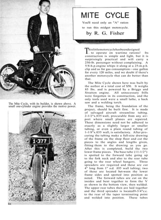
  • 1. The Mite Cycle, with its builder, is shown above. A small one-cylinder engine provides the motive power. MITE CYCLE You'll need only an "A" ration to run this midget motorcycle. by R. G. Fisher This little motorcycle has been designed . to operate on wartime rations! Its construction is simple and light, but it is surprisingly practical and will carry a 250-lb. passenger without complaining. A 5/8-h.p. engine whips it along at a 25-m.p.h. clip and as for gas consumption—one gallon for every 120 miles, and we doubt if there's another motorcycle that can do better than that. The Mite Cycle shown here was built by the author at a total cost of $50. It weighs 85 lbs. and is powered by a Briggs and Stratton engine. All unnecessary frills were forgotten in its construction, and the only tools used were a small lathe, a hack saw and a welding torch. The frame, being the foundation of the project, should be built first. It is made of salvaged aircraft streamline tubing. 2-1/2"x.035 wall, procurable from any air-port where small planes are repaired. These dimensions need not be adhered to exactly as a slightly larger or smaller tubing, or even a plain round tubing of 1-1/8"x.035 wall, is satisfactory. After pro-curing the tubing make a full-size drawing of the frame on the shop floor and cut the pieces to the angles and lengths given, fitting them to the drawing as you go. After this is completed, build the two lower frame pieces. The base tube (11-1/2") is spotted to the forward tube going up to the fork neck and also to the rear tube going to the rear wheel hangers. Three spreaders are required and these are cut 4" long from 1" o.d. .035 wall tubing; two of these are located bet-ween the lower frame sides and spotted into position as noted. The forward tubes are cut on the insides and bent together to form the V as shown in the bottom view, then welded. The upper rear tubes then are laid together and the third spreader is located 9-3/4" c.c. to the rear of the taper terminating point and welded into position. These tubes
  • 2.
  • 3. «f» . The brake plate, shown in the diagram below, is in-stalled as above. Brake band is anchored at bottom. Slotted hole allows for adjustment of the drive belt. 86 are cut on the inside 1/2" forward of the spreader and bent to form the taper as shown in the top view. The forward tube is located and welded to the upper rear tubes. The lower frame now is set on the floor and the uprights located and spotted, the upper frame is placed into position on top and spotted, the frames are welded together at the rear wheel hangers and welding of the whole frame proceeds, work being carried forward and each section completed as it is reached. Rear wheel hangers are cut out of 3/16" cold rolled steel, cut long enough to extend inside the frame 1", and after joggling, they are in-serted and leveled. It is important that the hangers are level, otherwise the Cycle will not balance; when level they are brazed in position. Before attaching the fork neck, it is necessary to procure the standard bicycle bearings and races that are used in the neck. A piece of 1-1/2"X.125 wall tubing is cut 6-1/2" long and each end is bored to take the races. A line is drawn on the floor, the frame is placed level on the floor straddling the line and a plumb line is then dropped from the center line of the frame at the rear wheel hangers to the line. Another plumb bob is attached to the fork neck, and the fork neck is spotted into position while both bobs are on the line. Then the frame is brazed to the neck, making sure the frame is plumb. En-gine supports are made of 1-3/4"x3/4"x1/8" angle iron and located according to the engine used. Holes through these members for en-gine bolts should be slotted to permit adjust-
  • 4. , A > - • • * » . ment of the belt. Foot rests are cut to individual needs from l"x.035 wall tubing and welded to the frame at an angle as shown. The frame is now complete except for seat-attaching lugs. An extra large bicycle seat is used and re-worked with the attachment for the seat neck removed. Pictures show the installation of the seat, but as seats vary, the attachment is left to the individual builder. A standard bicycle fork replacement neck is used on the fork and this is purchased at a bicycle shop. Upper fork plates are cut from 3/16" steel plate and rounded to fit the tubing used. Tubes are butted against the top plate and welded; the bottom plate is cut and placed between the tubes 1" below the top plate and this is also welded to the tubes. A 1" hole A standard replacement neck is used on the steering fork. The fork arms are bent forward at a 22° angle.
  • 5. Throttle feed is mounted on handle bar; brake is on the opposite side. Countershaft bearing supports are mounted to frame pieces as at right. Photo below shows countershaft belt drive and location of exhaust pipe. then is drilled through the center of both plates and the replacement neck slipped into these holes and welded on the lower side of the plates only. A 1/2" piece of material (tri-angular) is removed from both tubes as noted, then the tubes are bent up to an angle of 22° and welded. The front wheel hangers are then cut out and installed and the fork is complete. The handle bar is cut 23" long from l"x.035 wall tubing and the bicycle gooseneck is located in the center of the tube before bending. It is important that the gooseneck be in position before bending the bar otherwise it will not slip on. The bar should be bent to measurements given. Cold rolled steel rod 9/16" o.d. 6-3/8" long is used for the countershaft; chuck in the lathe and turn to measurements given. The .590 measurement should [Continued on page 132] Mechanix Illustrated
  • 6. Mite Cycle [Continued from page 88] be exact as the bearing will slip on the shaft if it is turned undersize. The pulley adapter is turned and since it is used for an arbor in turn-ing the large pulleys, it must be left long enough to chuck in the lathe and is cut off to size only after completion of the 6" pulleys. A retaining nut is used to lock the pulleys on the adapter during their machining, and this nut now is made and mated to the adapter. Two cast-iron blanks 3/4" wide and 6" in diameter are used for the 6" pulleys, and these can be secured at the local foundry. They are chucked in the lathe, first one side and then on the other. The pulley web, although thin (1/8"), is suffi-ciently strong. Upon completion of machining the web, a 1" hole is bored through the center and, with a boring bar, the diameter of the hole is en-larged to 1" .140 and threaded left hand 24 threads per 1". Using the adapter as a gauge, thread care-fully until the adapter will screw into the pulley with effort, for it should be a tight fit, and after this is completed, remove the pulley from the lathe and turn the other pulley in a like manner. Next drill the pulleys for the spanner wrench which must be constructed. The adapter is re-turned to the chuck and a pulley is screwed on with the aid of the spanner wrench, and the nut is screwed on to lock the pulley in place. A light cut is taken on the outer diameter of the pulley to true it up. A cut-off tool is placed in the tool rest and a cut is made in the middle of the pulley to a depth of 5/16". The compound rest is swung 19° to one side and the angle is cut into the pulley, then 19° the opposite direction and the angle cut from that side. Except for a little trimming in the bottom of the V, the pulley is now complete. This process is repeated on the other pulley. The extension on the adapter now can be cut off and the adapter drilled and tapped for the set screws. A smaller drive pulley of 2-1/8" is turned and the V is cut as on the large pulleys; a 9/16" hole is drilled through and the end is tapped for a 5/16" screw as noted. Bearing housings are made simply with 1-1/2"x.065 wall tubing brazed to a 1/4"x1"x3" cold rolled steel strap; the 3/8" tubing is then brazed on the 1-1/2" tubing and the unit is split with a hack saw. Two of these are required. The countershaft bearing supports are made of 18- gauge steel and are drilled to mate with the bear-ing housings. Bolt the bearing housings to the sup-ports and assemble the countershaft, putting the two New Departure 5202 bearings in place, and then install the adapter with one 6" pulley screwed to it. The bearing housings are slipped over the bearings and clamped into position. The whole assembly is put into place on the frame uprights and the countershaft bearing supports are spotted in position on the uprights. This makes sure that the countershaft will not bind when in-stalled on the frame supports. Bearing housings should be loosened and the countershaft removed 132 from the frame when the supports are welded. Two standard bicycle wheels 20x.l25 are used; these are 24-spoke front wheels complete with bear-ings and axles. One is used without change for the front wheel of the Mite Cycle. The hub is re-moved from the wheel to be used on the rear and the spoke holes are redrilled for 1/8" spokes. Chuck the hub in the lathe and turn the ends to 1" .180 then thread left hand 24 threads per 1". Use the large pulley as a gauge and thread until the pulley can be screwed on with effort. When both ends are completed, remove the hub from the lathe and re-spoke the rear wheel with 1/8" motorcycle spokes. These can be procured from an old motorcycle wheel and must be cut to 6-3/8" lengths and then re-threaded to fit the spoke caps. With the rear wheel re-spoked, screw a pulley permanently in place with the spanner wrench. Then machine the brake drum and screw per-manently in place on the opposite side of the wheel. The brake band is 18-gauge steel lined with regular lining cut to the size required. The band is a 3/4 type and is self-energizing as it has a tendency to wrap itself around the drum when the brake is applied. The brake plate is made of 1/8" cold-rolled steel and joggled 1/4"; the top slotted hole allows for adjustment of the rear belt. The band anchors on the lower bolt hole and actuates from a small bellcrank and rod anchored at the forward end. A standard bicycle handle-bar squeeze lever and cable is used to actuate the brake. The cover for the countershaft and engine pulleys is made of 22-gauge tin cut to streamline and has 2" flanges soldered to it. Now procure a set of standard 20x2 .125 fenders from the local bike shop and our Mite Cycle is ready to assemble. Install the front wheel and fender on the front fork, install the bearings in the fork neck and at-tach to the frame. Install the handle-bar goose-neck into the fork tube, line up and tighten. The engine is installed next and has a 2-5/16" pulley attached to the crankshaft. This is a die-cast pulley and may be purchased locally for about fifty cents. The countershaft is installed; the rear belt must be in position around the shaft before tightening the clamps, this rear belt being 1/2"x48". The large pulley is installed on the countershaft and a 1/2"x35-1/2" belt is used between engine and countershaft. Adjustments are made and the engine tightened securely. The gas tank has been left to individual taste, but if an injection carburetor is used, a standard one-gallon can, located inside the frame under-neath the seat, will be satisfactory. The can screw top is carefully cut out and a piece soldered over the hole; this screw-top portion then is soldered on the side and at the rear of the can. Small lugs also are soldered to the can, and it is installed with sheet-metal screws running through the [Continued on page 134]
  • 7. Mite Cycle [Continued from page 132] lugs into the frame members. The rear wheel is installed next, and here it will be found necessary to spread the frame slightly to clear the brake drum and pulley. Place the brake plate on the side shown and secure the rear wheel after ad-justing the belt. The rear-wheel hanger is drilled and tapped 10-32 and bolted through the slotted hole in the brake plate. The rear fender is bent out on the forward end and attached to the tank with a sheet-metal screw through a small lug soldered to the tank. 134