
Recommended
More Related Content
What's hot
What's hot (20)
Viewers also liked
Similar to 2602658 motor sled
Similar to 2602658 motor sled (20)
Recently uploaded
Recently uploaded (20)
2602658 motor sled
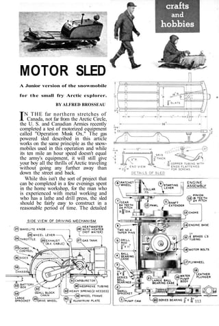
- 1. MOTOR SLED A Junior version of the snowmobile for the small fry Arctic explorer. BY AI.FRED BROSSEAU IN THE far northern stretches of Canada, not far from the Arctic Circle, the U. S. and Canadian Armies recently completed a test of motorized equipment called "Operation Musk Ox." The gas powered sled described in this article works on the same principle as the snow-mobiles used in this operation and while its ten mile an hour speed doesn't equal the army's equipment, it will still give your boy all the thrills of Arctic traveling without going any further away than down the street and back. While this isn't the sort of project that can be completed in a few evenings spent in the home workshop, for the man who is experienced with metal working and who has a lathe and drill press, the sled should be fairly easy to construct in a reasonable period of time. The detailed
- 2. drawings of the principal parts shown are clear and easy to follow. Large-scale work-ing drawings are also available from the MI Reader Blueprint Service and will be of considerable assistance in building the sled. The power plant in the original model shown in the photos consisted of a 1/3 to 1/2 horsepower, water-cooled Forster C W model gasoline engine, driving a wide toothed wheel through a reduction gear and chain drive. However, an optional installation could be made with a McCoy or Hornet air-cooled engine of the same horsepower. This would eliminate the auto heater radiator which is required to cool the Forster job. With either installa-tion, the 20-1 ratio between the engine and wheel develops enough torque at the drivewheel to move the average size youngster. The usual difficulty in starting the two cycle engine is overcome by gear-ing the kick starter down 5 to 1 so that a quick push really turns it over and the heavy flywheel keeps her going. To start the ball rolling on the con-struction, make the sled itself of either 114
- 3. Engine installed. Drive wheel is raised or lowered with lever. birch or maple, following the drawings for the details. A pair of cheap 4 ft. skis cut to the required length will save you a lot of time as they are already grooved for the runners. The next step is mount-ing the engine. The base is made of 1/8" CRS steel with the sides welded at right angles and everything kept as square as possible. Follow this up by making the small and large ball bearing housings (4 and 21), insert the bearings and then fit them to the sides. Use a piece of tissue between the gears to locate the bearings, drill through the housings and tap the sides for screws. The shaft extender parts (11) used to extend the crankshaft of the engine and to provide a means for locking the flywheel and the pinion gear, are then turned and threaded true. Com-plete these operations in the lathe before you cut the parts off. The pinion (12) is pushed on to the intake side of the crankshaft, the flywheel on the other end and the shaft extenders pushed through the bearings and screwed up tight. Follow this by making the motor bolts (16) and then drill 4 No. 36 holes in the base, tap 6-32 to match the mount-ing holes on the engine. The bolts are screwed into the base and locked with one nut while the engine is adjusted very carefully between the two other nuts and then locked down tight. The reduction shaft (5) which turns the drivewheel, operates the water pump and starts the motor, is made from 3/8"
- 4. drill rod, polished with emery cloth in the lathe or drill press so that the bear-ings will just slide on. The large gear and the sprocket are pinned to the shaft with No. 4 taper pins. The chassis (38) is then cut from 1/8 in. thick angle iron and welded. The engine base is bolted to it with 5-1/4 in. stove bolts and lock washers. The next operation is to make the wheel frame (39) from 5/16" CRS steel. Follow this by constructing the drive wheel (35) according to the details in the drawing. The radiator (28) required to cool the Forster engine can be made from the core of a used car heater. After testing it for leaks, the intake and out-let tubes are unsoldered and the core made into the radiator, following the 116
- 5. HEADLIGHT-drawings. An aluminum plate (40) is used to fasten it to the end of the plate sup-ports for the engine. The next parts to be made and installed are the carburetor float assembly (31) and the gas tank (27). The wheel frame is then fitted to the reduction shaft and the drive wheel mounted in place. An aluminum hood keeps the snow out of the mecha-nism. After the hood is in place, cut the drive chain to the correct length and con-nect the small sprocket and drive wheel, riveting over the removable link if necessary. The starter assembly (9) is made from 1/4 " CRS and the rachet wheel locked to the shaft with an Allen set screw in a 3/16" hole drilled 1/8" deep. Following this, the choke (13) is made from 1/16" brass, slid over the intake and clamped tight. The water pump (19) is then con-structed and put aside to be mounted against the side of the motor hood after it is installed. Use two screws tapped into the body of the pump to do this. The last part of the mechanism to be made and installed is the wheel lever (26). In opera-tion, the forward position is for starting or idling, the rear position engages the drive wheel for running. The sides of the motor hood consist of a welded frame covered with aluminum, bent to shape as shown in the drawing. At this point, the water pump previously mentioned is installed and rubber tubes connected to the radiator and engine block. Before the hood is completed, the two dry cells for the ignition should be mounted on one of the sides, using the aluminum battery clamp shown. The back of the hood is a piece of curved aluminum with an opening cut in it for the dashboard. This piece is screwed to the sides and the entire hood bolted to the chassis. The extensions at the front of the sides fit into the radiator shell. The dashboard itself is made from aluminum, drilled and slotted for the toggle switches, panel light, throttle and brake levers. The brake operates by simply cutting the ignition and using the drag of the wheel to stop the sled. After the dash and igni-tion wiring are completed, the board is fastened to the back of the hood, using four 6-32 screws. Next, make the top of the hood and hinge it to the radiator shell. The seat for the junior explorer should be made following the details in the draw-ings. Use two 14 in. thumb screws in slotted holes to make it adjustable. To finish the sled, paint the top of the hood and running gear one color and use a contrasting color on the sides. 117