
Recommended
More Related Content
What's hot
What's hot (20)
Viewers also liked
Similar to Power bike
Similar to Power bike (20)
Recently uploaded
Recently uploaded (20)
Power bike
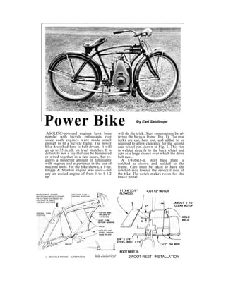
- 1. Power Bike By Earl Seidlinqer ASOLINE-powered engines have been popular with bicycle enthusiasts ever since such engines were made small enough to fit a bicycle frame. The power bike described here is belt-driven. It will go up to 35 m.p.h. on level stretches. It is definitely not a toy that can be hammered or wired together in a few hours, but re-quires a moderate amount of familiarity with engines and experience in the use of machine tools. For the bike shown, a 1-hp. Briggs & Stratton engine was used—but any air-cooled engine of from 1 to 1 1/2 hp. will do the trick. Start construction by al-tering the bicycle frame (Fig. 1). The rear forks are cut, bent out, and added to as required to allow clearance for the second rear-wheel rim shown in Fig. 4. This rim is welded directly to the back wheel and acts as a large sheave over which the drive belt runs. A 1/4x6xl3-in. steel base plate is notched as shown and welded to the frame. Care must be taken to have the notched side toward the sprocket side of the bike. The notch makes room for the brake pedal. 11*X4*X3/8* PLYWOOD FOOT REST (2) -CUT 1/2* NOTCH | —BICYCLE-FRAME ALTERATION BASE PLATE SHOULD RIDE 'HORIZONTALLY 2-FOOT-REST INSTALLATION REAR FORKS EITHER HEATED ANO BENT OUTWARD OR CUT ANO EXTENDED BY WELDING IN SMALL TUBULAR SECTIONS.. DIAGONAL TUBE — ORIGINAL POSITION . ABOUT 2' TO X CLEAR MOTOF ORIGINAL FORK POSITION -WELD WELD DIA. ROD
- 2. Holes are drilled in the base to take the engine hold-down bolts. The exact loca-tion of the holes will be determined by the mounting holes in the particular engine you use. Make sure that when the engine is bolted down its drive pulley lines up with the extra rear-wheel rim. The foot rests and their mountings (Fig. 2) are ad-ded next. For hooking up the engine, quite a few small parts must be made. The drawings contain all necessary dimensions. Two parts are tricky—the clutch and the brake. The latter utilizes the coaster brake al-ready on the bike. Its assembly is clearly shown in Fig. 3. A short length of chain is cut and run over the rear sprocket. The upper end is fastened to a 3-in. length of door spring, which in turn is anchored to the bike frame. The lower end is secured to a specially made chain connector and thence through a brake rod to a pedal. The clutch (Fig. 7), although it may seem complicated, is relatively simple. The clutch-operation diagram explains how it works. "When clutch arm, A, is pushed down, pivoting at point E, it pulls rod, D. thus working lever, B, and pulling idler pulley, C, from drive belt. This operation disengages the clutch. To reengage, slowly let up on the clutch arm. For locking the clutch in disengaged position, a 1/4-in. pin protrudes from the clutch arm. This rides in a notch in the spring-loaded locking bar. Gasoline is fed by means of either one of the handlebar grips (Fig. 8). Ream it out with sandpaper so it will slide and ro-tate easily over the handlebar, into the end of which a wooden plug and pin are driven. The plug must fit tightly enough so it can't turn. The pin tip fits into the thread of a 1/4"x4-in. bolt. The inner end of the bolt has a hole drilled through it to take the gas-feed wire, which in turn connects to the 4-REAR-WHEEL ALTERATION DOUBLE HIM REMOVE TIRE FROM CEMENT IN EXPLAINS NEED REAR-WHEEL RIM. RUBBER TAPE FOR WIDENED WELD SIMILAR FOR POSITIVE REAR FORKS STEEL RIM TO IT BELT TRACTION -ENGINE BASE MOUNTED ON RUBBER PADS OLD BED POSTS (ALREADY CURVED) ATTACH TAIL PIPE TO BRACE 5-EXHAUST SYSTEM CUT LOWER LEFT RK ARM Closeup of engine, below, clearly shows throttle assembly, position of the coil, and how the one-quart gasoline tank is mounted behind the engine.
- 3. Here's how the V-type drive belt is installed. Clearly evident are the drive pulley, the clutch pulley, and the extra welded-on rear-wheel rim. carburetor. A ^-in. hole is drilled through the handlebar, as shown, to let this wire, which must not interfere with the steering movements, out. To protect the wire, encase it in a length of curtain-hanger spring. All auxiliary parts of the engine, such as ignition coil or battery, must be mounted wherever there is room. Bicycle frames and engine parts differ; so no set rule can apply. The same holds true for the exhaust pipe. In this particular installation, the ex-haust pipe was made from an old iron bed post (Fig. 5). It fell into place without any alteration of curvature being necessary. The engine should be mounted on vibra-tion- dampening rubber pads, % in. thick by 2 in. dia. Further to absorb engine vi-bration, a coil spring from a bicycle seat is bolted to the front bar in such a position that it rides against the upper part of the crankcase (Fig 7). Standard equipment on the engine shown was a 3-in. drive sheave. Experimentation proved this to be slightly large. Instead of reducing it, the extra rear-wheel rim was increased proportionately by building up its diameter with rubber tape. This worked well and had the added merit of increasing the friction between belt and wheel rim. As shown in one of the photos, a piece was cut out of the rear fender to allow the belt to pass without scraping. A continuous V-belt may be pur-
- 4. chased at any hardware store, the proper length being determined by means of a string run over the belt track, allowing enough slack for clutch operation. To in-stall the belt, it will be necessary to cut the lower left rear fork, as shown in Fig. 6. A strip of 16-ga. tin, bent to a sleeve and bolted over the cut, as detailed, repairs the break and permits easy removal of the belt at any time. Complete the installation by adding a sheet-metal engine cover so your clothing cannot be damaged. To adapt this rig to your own particular size and type of bike and make of engine, a certain amount of experimentation will be necessary. For instance, several types of carburetor and sizes of fuel tank were used experimentally on the bike shown. It will be found, however, that drastic al-terations to the basic methods described won't be necessary since they are just about as simple and efficient as is humanly pos-sible. On the subject of engine maintenance, books could be written—in fact, books have bee?i written. They're called operation-and- maintenance manuals and the proper one for your engine may be obtained by writing to the manufacturer. Two general notes of caution apply to all air-cooled en-gines— always maintain the proper oil level in the crankcase and never fill the gasoline tank while the engine is running. • Lefthand view of engine showing clutch assembly. Here the clutch is engaged. To disengage, step on foot bar, thus pulling idler away from V-belt.