Effortless Driving Experience Premier Mercedes Sprinter Suspension Service
2532773 suitcase-powercycle v2
1. Suitcase Size POWERCYCLE
Part 1. Here's some midget transportation that will tuck away in your
car's trunk—ready and eager for side trips or just plain motor sport
By CARL S. BATES
AS AN errand runner or for
short distance commut-ing,
this midget motor-scoot
would be hard to beat. De-signed
so that the handle bars fold
down and the foot pedals fold in,
its 12-1/2 x 24 x 40-in. foldup size
will easily fit into the trunk of
your car, or even a small case
you can build for it (Fig. 1)—
with rollers that enable you to
run it along without lifting the
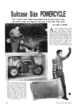
Ideal to take along for those side
trips, this 75-pound powercycle
can be carried in your car trunk
(top photo), or stored in a 13-1/2X
25-1/2x41-1/2-in- suitcase-type box
(lower photos), equipped with
small wheels for easy rolling.
Note how handlebars and brake
pedal rest fold up to give you
minimum width, and the 2-1/2-hp
Briggs and Stratton engine used
here has a gas tank that tucks
inside the framing. A spare gas
container fits inside suitcase box
as shown above.
126 SCIENCE AND MECHANICS
2. Craft Print Project
No. 215
FEBRUARY, 1955
Pretty 5 foot, 7 inch model tries out the midget power scoot. High
schoolers may find this an ideal form of transportation to-and-from
school or for errand running. It requires a regular motor vehicle license.
127
3. Note clutch and rear wheel drive, and folded-up front
foot rest. In Part 2, we will show you how to add a
hand-operated rear wheel brake (not shown here) in
addition to the foot-powered front wheel brake, for
those states that require a brake on each wheel.
entire weight. Best news about this pint- size
powercycle is its cost—about $100 for materials,
and $10 to $15 for welding if you don't do this
part of the assembly yourself. Commercial
powercycles regularly sell for over $200 to $400,
and we don't know of any domestic commercial
model that folds up the way this fellow does.
The model shown here is powered by a 2-1/2 hp
Briggs and Stratton engine and, to keep down
cost and space displacement, uses an automatic
clutch pulley (acting like a fluid drive) and no
gear shift. The speed you will get out of this
combination of course won't be sensational, nor
is any unit designed with such a low horse-power
engine intended for winning hill climbs.
But it should get you there and back with ease.
For compactness, a retrievable pull starter is
recommended, as opposed to either the rope
type (that's hard work, son) or the kick type
(which would stick out too far for driving
comfort).
Make the frame (Fig. 3) first. Thin-walled
electrical conduit (T.W.C.) is used for all frame
parts. Start by laying out the frame members
full-size on heavy paper or cardboard from the
dimensions given in Fig. 2, or use the craft
prints which show these frame pieces full size.
Cut the straight piece (A in Fig. 2) and fit the
128 SCIENCE AND MECHANICS
5. kingbolt bushings in place. These are turned from 1/2 to
3/8-in. malleable-iron pipe bushing reducers and should be
in place before the frame parts are welded together.
If you do not have a metal-turning lathe and must have
the lathe work done outside, the rear axle (Fig. 4) should
also be made at this time. Then cut piece B (Fig. 2) to
length and cut and form one end to fit snugly around
piece A at 115°. Make a wooden jig (Fig. 5) to support the
pieces when fitting and later welding. Slide a 4-in. length
of 1/2-in. conduit in the other end of piece B and flatten
the end by gripping in a machinist's vise and drawing up
tightly rather than hammering. If your vise is a small one
it may be necessary to heat the end of the conduit before
flattening.
Next, drill the 13/32-in. hole in piece B, and saw the trian-gular
seat-post brace from 3/16 x 1-in. band iron. Then weld
pieces A and B together while they are clamped with the
wooden jig, and also weld the triangular piece to the end
of piece B. Thin-walled conduit is plated with a rust proof
material which must be removed before welding. Use a
file or abrasive wheel to remove at areas where welding is
to be done. A purchased or rented electrician's conduit-bending
tool can be used to make the bends. By leaving
the conduit extra long you will have sufficient leverage to
easily bend it. Bend the conduit to the approximate radius
and angle then test for correct bending angle by placing
the conduit directly over the full-size drawing.
Next, bend, flatten and drill pieces C, D, E, F (Fig. 2). Note
that these pieces are pairs so make one each for right and left
side of frame. Cut and thread a 3/8-in. steel rod for the frame
tie-rod (Fig. 4) and use a 8-3/4-in. length of 3/8-in. pipe for the
tie-rod spacer. Now assemble all of the frame pieces with
bolts. The seat-post clamp must be in position. The rear axle
will serve as a spacer during this assembly. Make the as-sembly
jig (Fig. 6) and clamp to the frame to hold the pieces
in proper alignment. You may find that further fitting will
be necessary to get a snug fit where pieces F and A join.
130 SCIENCE AND MECHANICS
6. Use a C-clamp to hold this joint together when
welding. Cut, bend and fit brace G (Fig. 2) to
the assembled frame, and then weld in position.
Also weld the conduit where pieces E and F
join, but do not weld to, the tie-rod or spacer.
If you do not have a welding outfit and must
have the welding done at your local job shop,
make up the fork pieces (Figs. 2 and 7) before
having the frame welded so that all parts can
be welded at once. Cut two 19-1/2in. lengths of
3/4-in. TWC ( H in Fig. 2) and two 8-in. lengths
of 1/2-in. TWC. Slide the 1/2-in. TWC into the
3/4-in. TWC and flatten to 1/2 in for a distance of
6 in. from one end. Lay out, drill and tap all the
holes in pieces H. If possible, clamp the two
pieces together when drilling so that the holes
line up perfectly. Make the front axle and
quill axle (Fig. 4) at this time so that they can
be used to clamp the fork parts together during
welding. Cut the two angle-iron' pieces (J in
Fig. 7). Clamp both angle-iron pieces together
when drilling so that the 15/16-in. holes will be
equally spaced in both pieces. Unless you have
a metal-turning lathe, have this drilling done at
your local machine shop. Also have two 2-in.
lengths of 1/2-in. standard pipe bored or drilled
out to take 1/2-in. TWC for handlebar clamps (K
in Fig. 3). Then cut the clamps lengthwise with a
hacksaw. File a semi-circle in the top ends of
pieces H to take the handlebar clamps (Fig. 2).
Make pieces L in Fig. 3 from 1 x 1-in. angle iron.
Cut, bend and drill pieces M in Fig. 3 and bolt to
pieces J before welding . Then assemble pieces H
and J using C-clamps and fit it temporarily to the
frame with the kingbolt to assure a close
and smooth turning action. Be sure that pieces
H and J are at right angles to each other before
welding. Clamp and weld pieces K to each H
piece and upper J piece with saw cuts to the
center of the fork facing each other as shown
in Fig. 3. Then position and weld pieces L. to
pieces K only. They are not welded to upper J
piece. Drill 9/32-in. holes through pieces L and tap
upper K piece 1/4-28 for 1/4-28 handle-bar clamp
bolts.
Now cut and bend the handle bars (N in Fig.
2) and insert into clamps K. Tighten the 1/4-
in. bolts until the handle bars can just forcibly
be swung down or up. Do not drill the holes
through pieces K and N for the locking pins O
until the powercycle is completed because the
exact driving position will vary somewhat de-pending
upon the height of the rider.
Make and install the engine support bars (P
in Fig. 7) after the frame is welded. The U-bolts
allow the engine to be moved forward or
backward for belt tension adjustment. Do not
drill the holes for mounting the engine until
the drive pulley on the rear wheel is installed.
Cut and bend the kick stand pieces Q and R as
in Fig. 7. Tighten the 5/16-in. bolt and use a nut
to lock and adjust the bolt tension so that piece
R will stay in the up or down position by fric-tion.
Use a lock washer between pieces Q and
R if necessary. Then bolt the kick stand unit
to the frame with the rear right-hand, engine-support-
bar U-bolt. Make the two frame fender
brackets (Fig. 7) and bolt to the frame for the
rear fender, which will be installed later.
Part 2, appearing in the next issue, will show
you how to assemble the engine, drive belts,
brakes, throttle controls and accessories.
FEBRUARY, 1955 131
7. Suitcase Size
POWERCYCLE
Believed to be the
s m a l l e s t powercycle
that will comfortably
carry an adult, this
vehicle can be folded
up to lit into most car
trunks.
By CARL S. BATES
, PART 2
Craft Print Project No. 215
WHEN the powercycle frame is com-pletely
assembled (part 1, S&M Feb-ruary,
1955), your next step is to in-stall
the rear-wheel assembly. Inasmuch as
this is a trial assembly for cutting and fitting
the parts to proper size, leave the rear fender
installation until later after the frame is
painted. The rear wheel mentioned in the
materials list, part 1, comes complete with
flange and threaded lugs for mounting the
driven pulley and rear brake drum. Two
driven pulleys are available. A 9-in. dia. one which will give
the powercycle maximum pulling power for hilly streets and
an 8-in. dia. pulley which "will give the powercycle the maxi-mum
speed. In either case drill through the heads of the three
pulley-mounting cap screws and wire as in Fig. 9 to prevent
their loosening and falling out. Cut the two rear-axle spacers
(S in Fig. 9-A) from 3/4-in. O.D. x 18-gage steel tubing slightly
oversize and file ends until tubing spacers can just be turned
by hand when assembled with the rear wheel in the frame
and axle nuts drawn up tight. The spacers merely keep the
. V.
A—Lever stop plate. B—Hand-brake lever. C—Drive pulley. D—Engine belt-guide
bracket. E—Cable brackets. F—Clutch-control wire. G—Foot pedal. H—Spring.
J—Movable idle-pulley arm. K—Idle pulley. L—Driven pulley.
Left side of powercycle showing rear-wheel hand brake and foot-pedal
operated idle-pulley type of clutch.
APRIL, 1955
wheel in position and must not put a
load on the rear-wheel bearings. It
will be necessary to remove the bolt
holding one side of the frame fender-bracket
to spread part C of frame
(Fig. 3, part 1) over the ends of the
rear axle. Place the drive belt on the
driven pulley before installing the
rear axle assembly in the frame. Use
a 45-in. long 1/2-in. V-belt with a 9-in.
dia. pulley and a 43-in. long 1/2-in.
V-belt with an 8-in. dia. pulley.
Place the powercycle on a box and
clamp down (Fig. 10) to facilitate
119
8. working on the machine. Then place the engine
on the engine support bars. At this point you
will have to decide whether you are going to use
the automatic clutch and drive pulley or the foot-controlled
belt-tightener type of drive clutch
(Fig. 8). In either case place the pulley on the
engine shaft as close to the engine as possible
and line up the drive pulley on the engine shaft
with the driven pulley on the rear wheel with a
yardstick or straightedge (Fig. 11). Then mark
the location of the four engine mounting bolt
holes on the engine support bars. Remove the
engine and support bars and drill the 3/8-in. holes
in the bars. Reassemble the support bar to the
frame but do not tighten the U-bolt nuts because
the position of the bars are determined by the
length and tension of the drive V-belt. The en-gine,
however, can be mounted on the bars and
permanently bolted to the bars with 5/16-in. cap
screws drilled for cotter pins.
If you decide upon the foot-controlled, belt-tightener
type of clutch, weld a 1/8x1-1/2x1-1/2in.
band-iron pad on the outside of both sides of the
fork (H in Fig. 2, part 1) and drill and tap
5/16-24 through the pad and fork tubing. Make
two foot pedals (Fig. 12), one right and one left,
and bolt in place on the fork. Use castle nuts
120 SCIENCE AND MECHANICS
9. and drill the cap screws for cotter pins. Tighten
the cap screws just enough to allow the foot
pedals to be moved up and down without any
play. Grease the bearing surfaces.
To support the movable idle-pulley arm, lay
out, saw and bend the idle-pulley bracket (Fig.
9-B) and fasten to the left side of the front en-gine
support bar with the U-bolt (Fig. 9). If
the rear-wheel hand brake is to be included (re-quired
by some states), you will save yourself
some time by making the hand-brake bracket
(Fig. 9-B) and installing it at the same time you
bolt the idle-pulley bracket in place.
When working on front and rear wheel assemblies,
place powercycle on a box and secure to top with
a C-clamp.
To make the movable idle-pulley arm, heat a
3/8-in. dia. steel rod to make good sharp bends
(Fig. 9-B). It may be necessary to file the bear-ing
surfaces of the rod slightly as indicated, to
seat the washers at right angles to the rod. Drill
the 3/32-in. hole for the control wire. Use two
3/8-in. I.D. ball bearings (see materials list) for
the idle pulley and assemble with washers and
cotter pins.
Make the two cable brackets (Fig. 9-B) and
bolt in position. The cable control wire is a
length of automobile choke wire cut to length so
that it will reach from the left foot pedal to the
movable arm (Fig. 9). Allow enough slack so
that the control wire will not interfere with
APRIL, 1955 121
10. steering the front wheel. Be sure to bolt a belt-guide
bracket to engine (Fig. 8) if the idle-pulley
type of drive is used. This bracket will
prevent the belt from being thrown off the en-gine
pulley. Adjust the belt tension by sliding the
engine support bars on the frame; then tighten
the U-bolts.
If the rear-wheel hand brake is to be included,
make the parts de-tailed
in Fig. 9-B
and temporarily
install them (Fig.
9) at this time. Be
sure to counter-sink
the brake-band
rivets. If you
do not have the
tools to do this,
have your local
motorcycle - repair
shop mount the
brake-band lining.
One additional
h o l e must be
drilled through
the rear engine
support bar for
the brake anchor
strip. This can be
merely marked at
t h i s t i m e and
drilled later when
the parts are dis-a
s s e m b l e d for
painting. The rear-wheel
b r a k e is
mentioned in the materials list of Part 1 has the
brake drum welded on. Cut two spacers (Fig.
12-A) 1 in. long from the 3/4-in. O.D. x 18-gage
steel tubing for the rear-axle spacers and file and
fit so the total length of both spacers and wheel
hub are exactly equal to or slightly less than the
length of the front quill axle previously made.
This is important because the spacers must not
controlled with
the hand lever
(Fig. 14). Use a straightedge to line up drive pulley
The front wheel on engine with driven pulley on rear axle.
122 SCIENCE AND MECHANICS
11. bear against the ends of the front-wheel bearing
but only keep the wheel centered with the mini-mum
amount of play.
Place the wheel, quill axle and spacers be-tween
the fork (Fig. 12) and slide the front axle
through the fork and quill and tighten. Make
the front brake band (Fig. 12-A), insert the
5/16-in. bolts and assemble to the brake pedal
and fork as shown in Figs. 12 and 13. Use a
spring as indicated to keep the brake pedal in
the off position.
Now with the powercycle on the floor and the
seat clamped in place, prop up the frame with
blocks of wood to prevent it from falling over.
Then mount the powercycle and assume a normal
riding position with your feet on the front pedals.
Move the handle bars up and down until they
are at the most comfortable driving position.
Turn the front wheel from side to side as you
would when steering to make sure the handle
bars clear your knees. When the handle bars
are in the correct position for you, drill a 5/32-in.
hole through the handle-bar clamps (N in Fig. 3,
part 1) and the handle bars. Make two locking pins (Fig. 8)
and insert in the drilled holes. To prevent the locking pins
from getting lost when the handle bars are in the folded-down
Right side of front wheel showing front-wheel brake
position, tie the locking pins to the frame with a strong
cord.
The carburetor-control assembly is next. Use an ordinary
bicycle hand-brake lever on the right handle bar and an
automobile flexible choke cable and wire from the hand lever
to the carburetor-valve lever (Fig. 14). A stronger spring
must be used on the carburetor lever to assure smooth, en-gine-
speed control.
With everything in working order, take the powercycle out
for a test run and make any minor adjustments necessary.
When you are satisfied that everything is in good working
assembly.
A—Hand lever. B—Rear-wheel hand-brake lever. C—Carburetor-control wire.
Speed is controlled with hand-operated gas throttle level on the
right handle bar.
APRIL, 1955 123
•«sfc»*^
12. order disassemble the powercycle and paint the
frame, wheels, brackets and pedals. Use a metal
undercoater first followed by two coats of auto-mobile
enamel. The original powercycle frame
is painted bright red, the wheels yellow and the
handle bars and hand-brake lever left the rust-proof
metal finish.
While the paint is drying, make the front and
rear fender brackets (Fig. 15). Both the front
and rear fenders are cut from one large-size,
chrome-plated rear bicycle fender. After cutting,
the fenders can be easily flattened somewhat to
make them wide enough for the powercycle
wheels. Drill and bolt the fenders to the frame,
using lock washers on all bolts to prevent loosen-ing
due to vibration. Fasten a rubber bicycle
mud splasher to the front fender and an 1-1/2-in.
dia. red reflector on the rear fender for a tail
light. If the powercycle is to be used at night,
a battery-powered bicycle head lamp should be
fastened to the fork as shown. Although not
necessary, a sheet aluminum oval-shaped disc
with the owner's initials painted on can be bolted
to the front fork to give it that custom-built look.
You are now ready to make the final assembly.
Carefully fit each part together to avoid scratch-ing
the paint and be sure to use castle nuts and
cotter pins on all of the cap screws. Use two
nuts locked together on the engine support bar
U-bolts. Plans for the powercycle suitcase are
shown in Fig. 16. Although the suitcase is not
necessary when carrying the powercycle in your
car, it will come in handy for storage or trans-porting
the powercycle by truck or train.—END
Whistling Car Motor
• A whistling tea kettle may have a cheerful
sound, but a whistling car motor is just plain
annoying. In such a case, check the bolts holding
intake manifold to the engine. Tightening these
bolts will stop the whistling sound and improve
engine performance.—CHARLES PATTI.
Rotating Seed Treating Machine
WELD at the points of contact a length
of 3/4 inch pipe extending through holes
tapped diagonally in each head of an oil drum.
Two sections of 3/4 inch shafting, 6 and 4-
inches long, are welded into the pipe.
A door fits over a 14-inch by 12-inch open-ing,
with butt hinges and a 2-inch bolt weld-ed
on opposite sides. Door is made dust-tight
by welding on the drum a piece of angle iron,
1 by 1 by 1/4 inches, with a gap cut in one
side. Frame is of 1 inch pipe, welded. Legs
are 3 feet long and are braced with 3/4 inch
pipe welded to the legs.
All welding was accomplished with 1/8 inch
mild steel shielded arc electrode with the
machine set at 120 amperes. A 12-inch V-pulley
is attached to the shaft, and a 1/3
horsepower electric motor is mounted on a
floating base. With the fitting of belts, the
machine is ready for operation. (Data and
illustrations are from award paper by James
D. Carter in The James F. Lincoln Arc Weld-ing
Foundation's Agriculture and Scholarship
Program).
124 SCIENCE AND MECHANICS
13. Fun In the Park
The enclosed picture shows your powercycle
(Craft print 215) with my 7-year-old son Tom
astride. He and other children sure do enjoy
Cont.
riding the cycle, which they do in a park. It
is also a must with the adults and I sure had
a lot of fun building it.
32 May Street ANTHONY ROGERS
Fall River, Massachusetts
It's hard not to have fun with that cycle, Tony.
Worth an "A" Grade
Decided to use your
plans for building a suit-case
size powercycle
(Craft Print 215) for a
Forging and Welding
course in which I am en-rolled
at Bowling Green
State University, Bowl-ing
Green, Ohio. I start-ed
production on the
challenging project Feb-ruary
10,1958 and had it
completed by April 14,
1958. It only took me
nine weeks of class time!
I used a 2-3/4 hp Briggs
and Stratton engine with
a 2-in. centrifugal clutch
pulley on the motor and
a 9-in. pulley on the rear
wheel. This combination
gives me a top speed of
33 mph. The pick-up is
good, and it climbs
grades exceptionally
well, and attracts more
attention here than a
Cadillac convertible. The
lights are powered by a
generator which oper-ates
off the rear wheel. I
mounted both the foot-operated
front wheel brake and the hand-operat-ed
rear wheel brake. Great job on your cycle.
SCIENCE AND MECHANICS
Jack-Shaft for Those Hills
Here's a power-cycle
that I built
from your Craft
Print 215. I fol-lowed
the plans,
but I also added a
jack-shaft to gear
down the motor
so it has power to
climb the hills
where I live. I
have an automat-ic
clutch with a
belt to the jack-shaft,
and from
the jack-shaft to
the wheel I used
a chain drive. This
prevents a max-imum
of slippage. I am very pleased with its
performance, and I have only you folks to thank.
243 Hamilton Road BART CAKLSON
Chappaqua, New York
A nice job of adapting the plans to fit your
needs, Bart. Of course, where there's no hill
problem, leaving off the jack-shaft, chain-drive
arrangement will permit more speed.