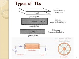
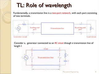
The document presents an overview of transmission lines (TLs), explaining their purpose in transmitting energy between various components. It covers the concepts of lumped and distributed elements, the relevant wave phenomena, and models for transmission line equations, particularly focusing on lossless and distortionless transmission lines. Additionally, the document discusses the terminations of transmission lines and the implications of reflections in voltage and current propagation.


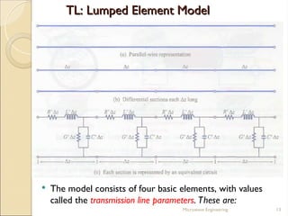


![RF Circuit Design - [Ch1-2] Transmission Line Theory](https://cdn.slidesharecdn.com/ss_thumbnails/ch1-2-150613064349-lva1-app6892-thumbnail.jpg?width=640&height=640&fit=bounds)


