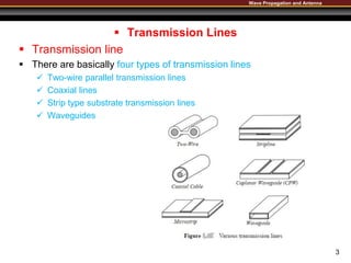
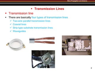
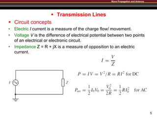
WavePropagationandAntenna
TransmissionLines(1/2)
March, 2019
Department of Electrical Engineering
Balochistan UET Khuzdar
Wave Propagation and Antenna
 Transmission Lines
 Transmission line
 A transmission line is a connector which transmits energy from one
point to another.
 The study of transmission line theory is helpful in the effective usage
of power and equipment.
 There are basically four types of transmission lines
 Two-wire parallel transmission lines
 Coaxial lines
 Strip type substrate transmission lines
 Waveguides
 While transmitting or while receiving, the energy transfer has to be
done effectively, without the wastage of power.
 To achieve this, there are certain important parameters
which has to be considered.
2
Wave Propagation and Antenna
 Transmission Lines
 Transmission line
 There are basically four types of transmission lines
 Two-wire parallel transmission lines
 Coaxial lines
 Strip type substrate transmission lines
 Waveguides
3
Wave Propagation and Antenna
 Transmission Lines
 Transmission line
 There are basically four types of transmission lines
 Two-wire parallel transmission lines
 Coaxial lines
 Strip type substrate transmission lines
 Waveguides
4
Wave Propagation and Antenna
 Transmission Lines
 Circuit concepts
• Electric I current is a measure of the charge flow/ movement.
• Voltage V is the difference of electrical potential between two points
of an electrical or electronic circuit.
• Impedance Z = R + jX is a measure of opposition to an electric
current.
5
Wave Propagation and Antenna
 Transmission Lines
 Lumped and Distributed Element Systems
• Lumped element system
• The current and voltage along a transmission line may be considered
unchanged (which normally means the frequency is very low). The
system is called a lumped element system.
• Distributed element system
• The current and voltage along a transmission line are functions of the
distance from the source (which normally means the frequency is
high), thus the system is called a distributed element system.
6
Wave Propagation and Antenna
 Transmission Lines
 Transmission Line Model
7
 If we divide the transmission line into many (almost infinite) short
segments of length ∆𝑧, which is much smaller than the wavelength of int
erest, each segment can then be represented using a set of lumped ele
ments.
Wave Propagation and Antenna
 Transmission Lines
 Transmission Line Model
8
 To make the analysis easier, the equivalent circuit of the segment of the tra
nsmission line is simplified in the below figure, where
R = R1 + R2 and L = L1 + L2.

02 Lecture Transmission Lines 02.pptx

  • 1.
  • 2.
    Wave Propagation andAntenna  Transmission Lines  Transmission line  A transmission line is a connector which transmits energy from one point to another.  The study of transmission line theory is helpful in the effective usage of power and equipment.  There are basically four types of transmission lines  Two-wire parallel transmission lines  Coaxial lines  Strip type substrate transmission lines  Waveguides  While transmitting or while receiving, the energy transfer has to be done effectively, without the wastage of power.  To achieve this, there are certain important parameters which has to be considered. 2
  • 3.
    Wave Propagation andAntenna  Transmission Lines  Transmission line  There are basically four types of transmission lines  Two-wire parallel transmission lines  Coaxial lines  Strip type substrate transmission lines  Waveguides 3
  • 4.
    Wave Propagation andAntenna  Transmission Lines  Transmission line  There are basically four types of transmission lines  Two-wire parallel transmission lines  Coaxial lines  Strip type substrate transmission lines  Waveguides 4
  • 5.
    Wave Propagation andAntenna  Transmission Lines  Circuit concepts • Electric I current is a measure of the charge flow/ movement. • Voltage V is the difference of electrical potential between two points of an electrical or electronic circuit. • Impedance Z = R + jX is a measure of opposition to an electric current. 5
  • 6.
    Wave Propagation andAntenna  Transmission Lines  Lumped and Distributed Element Systems • Lumped element system • The current and voltage along a transmission line may be considered unchanged (which normally means the frequency is very low). The system is called a lumped element system. • Distributed element system • The current and voltage along a transmission line are functions of the distance from the source (which normally means the frequency is high), thus the system is called a distributed element system. 6
  • 7.
    Wave Propagation andAntenna  Transmission Lines  Transmission Line Model 7  If we divide the transmission line into many (almost infinite) short segments of length ∆𝑧, which is much smaller than the wavelength of int erest, each segment can then be represented using a set of lumped ele ments.
  • 8.
    Wave Propagation andAntenna  Transmission Lines  Transmission Line Model 8  To make the analysis easier, the equivalent circuit of the segment of the tra nsmission line is simplified in the below figure, where R = R1 + R2 and L = L1 + L2.

Editor's Notes

  • #3 Resistance, capacitance, inductance, conductance
  • #4 Resistance, capacitance, inductance, conductance
  • #5 Resistance, capacitance, inductance, conductance