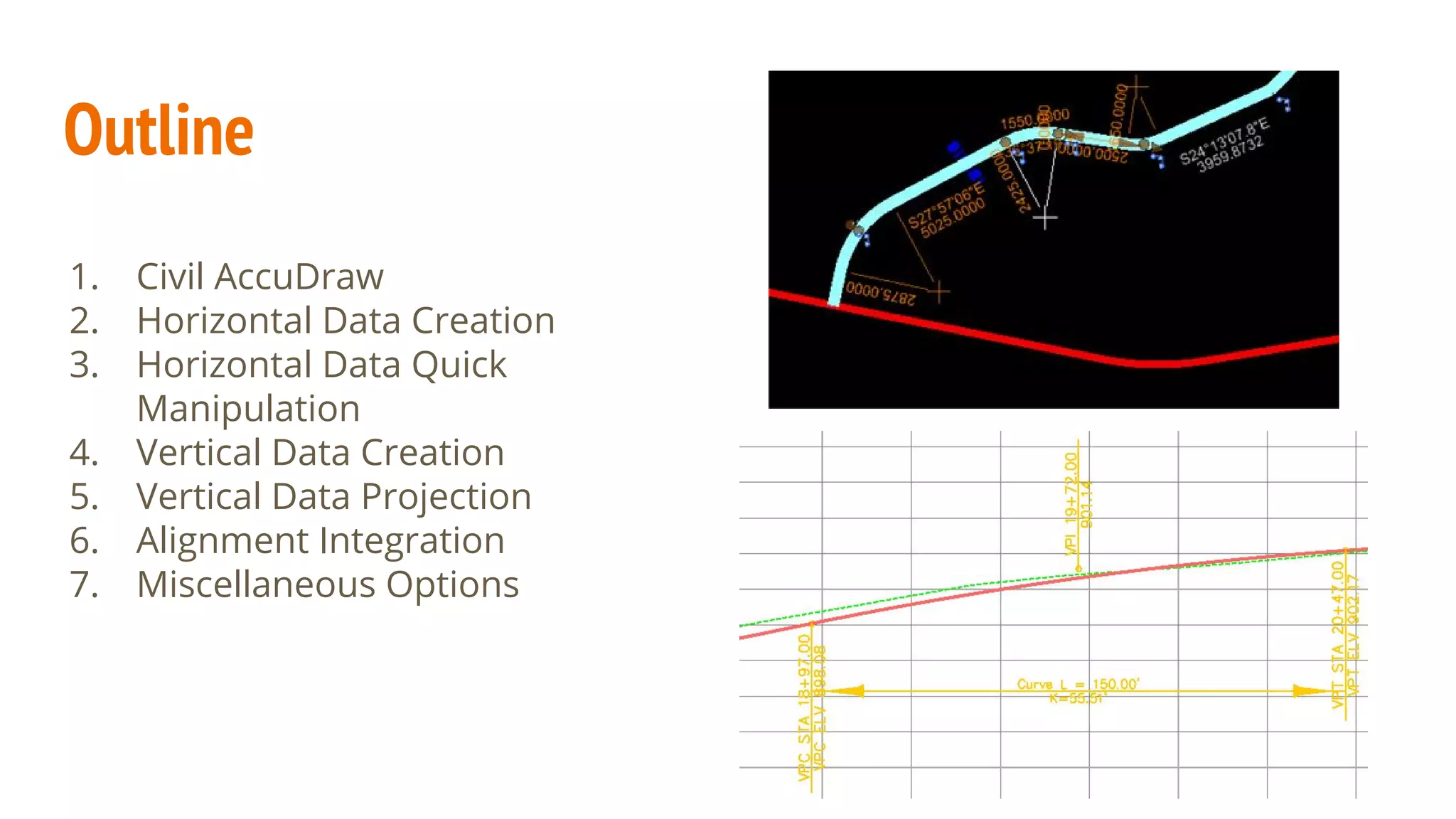
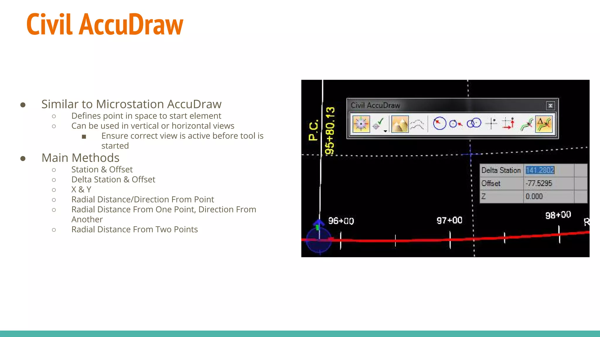
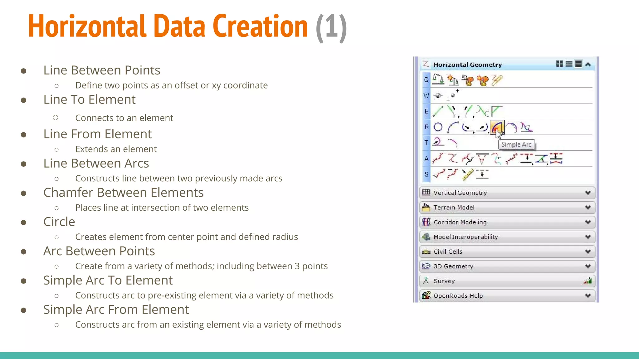
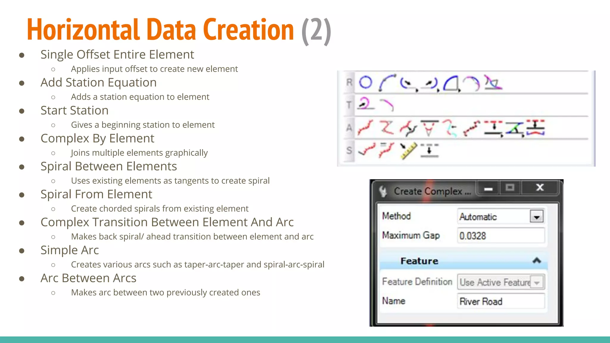
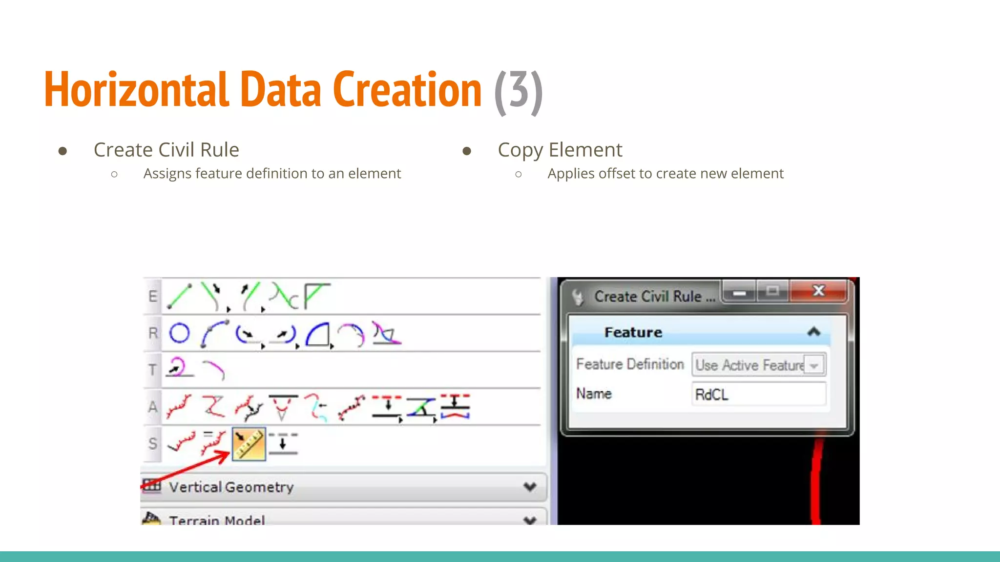
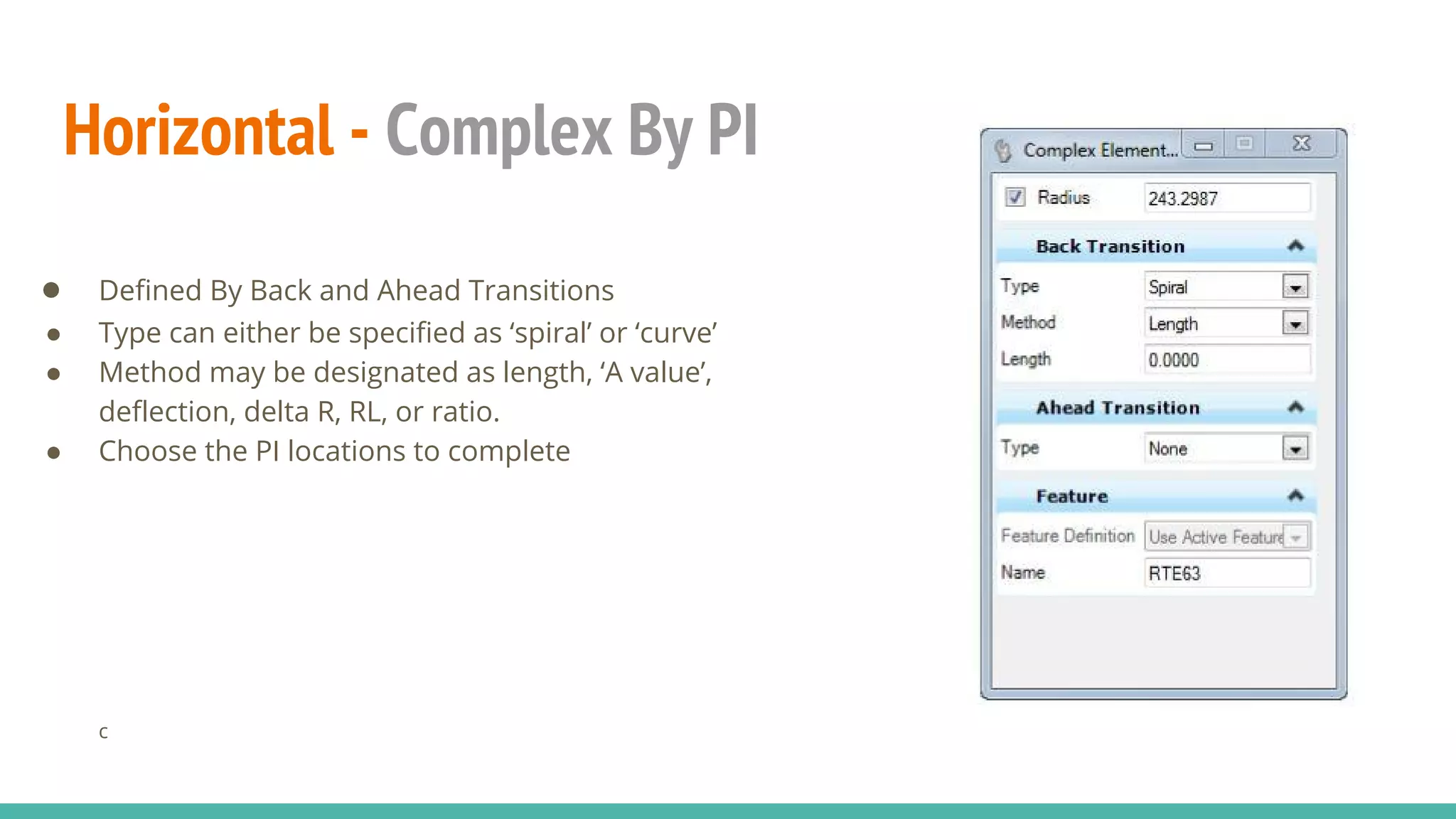
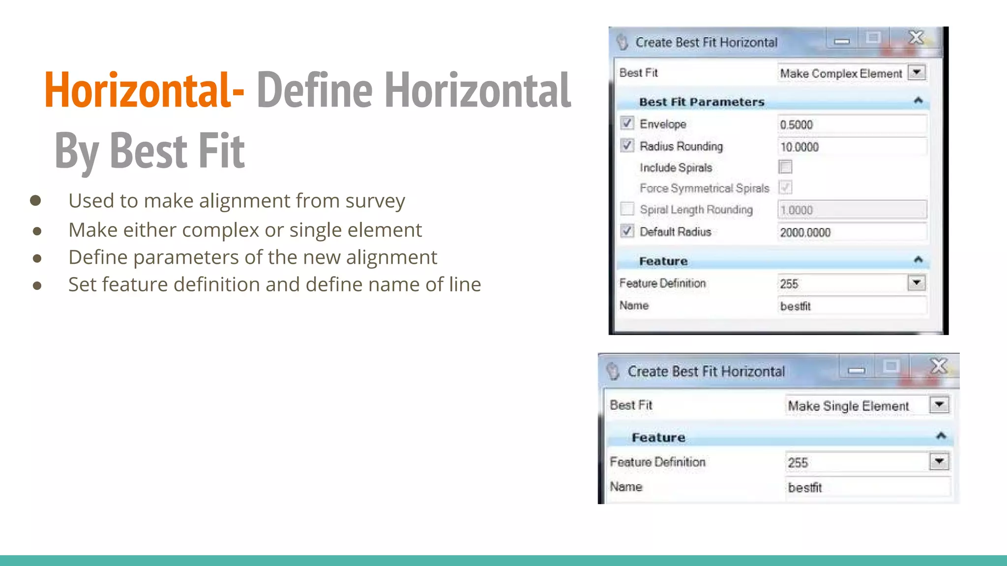
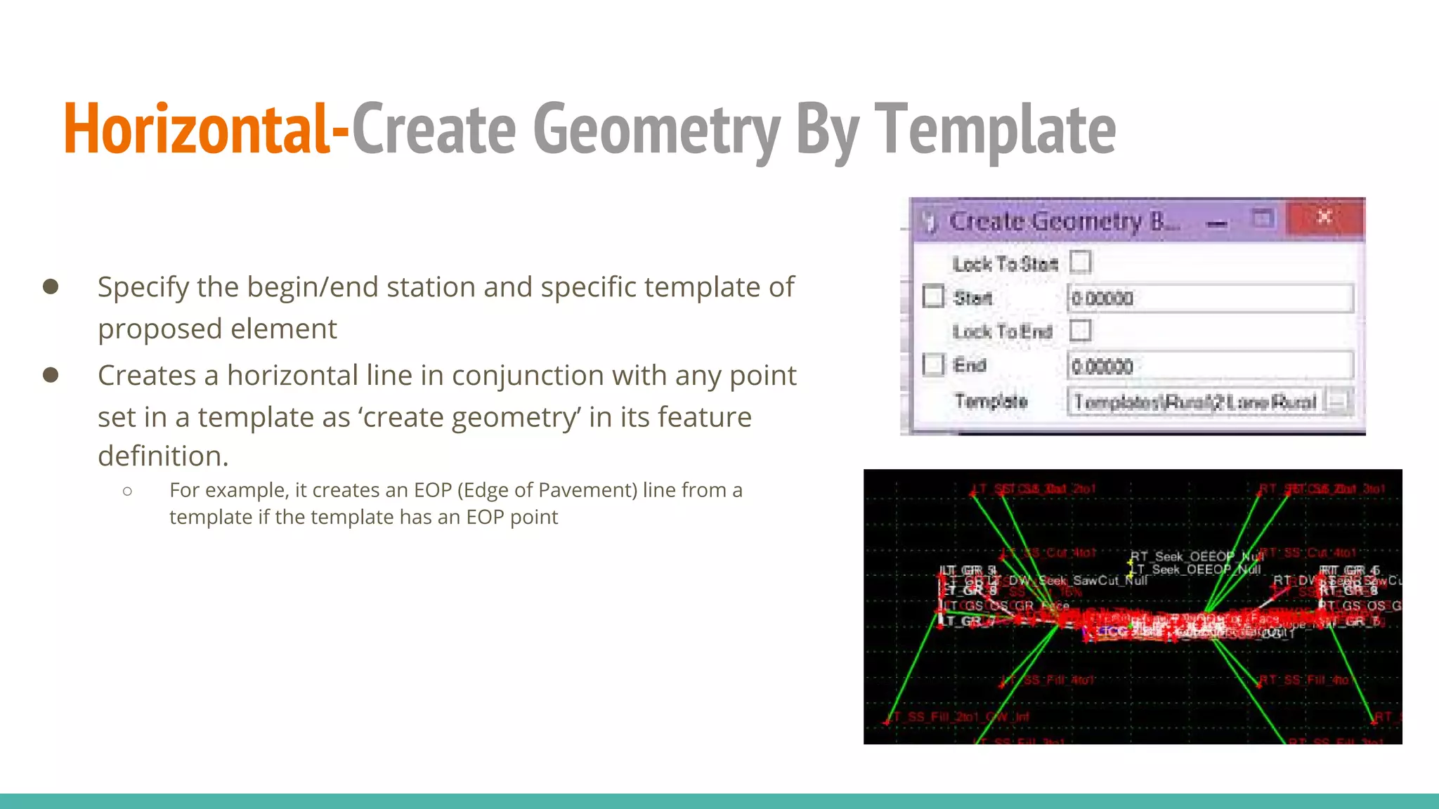
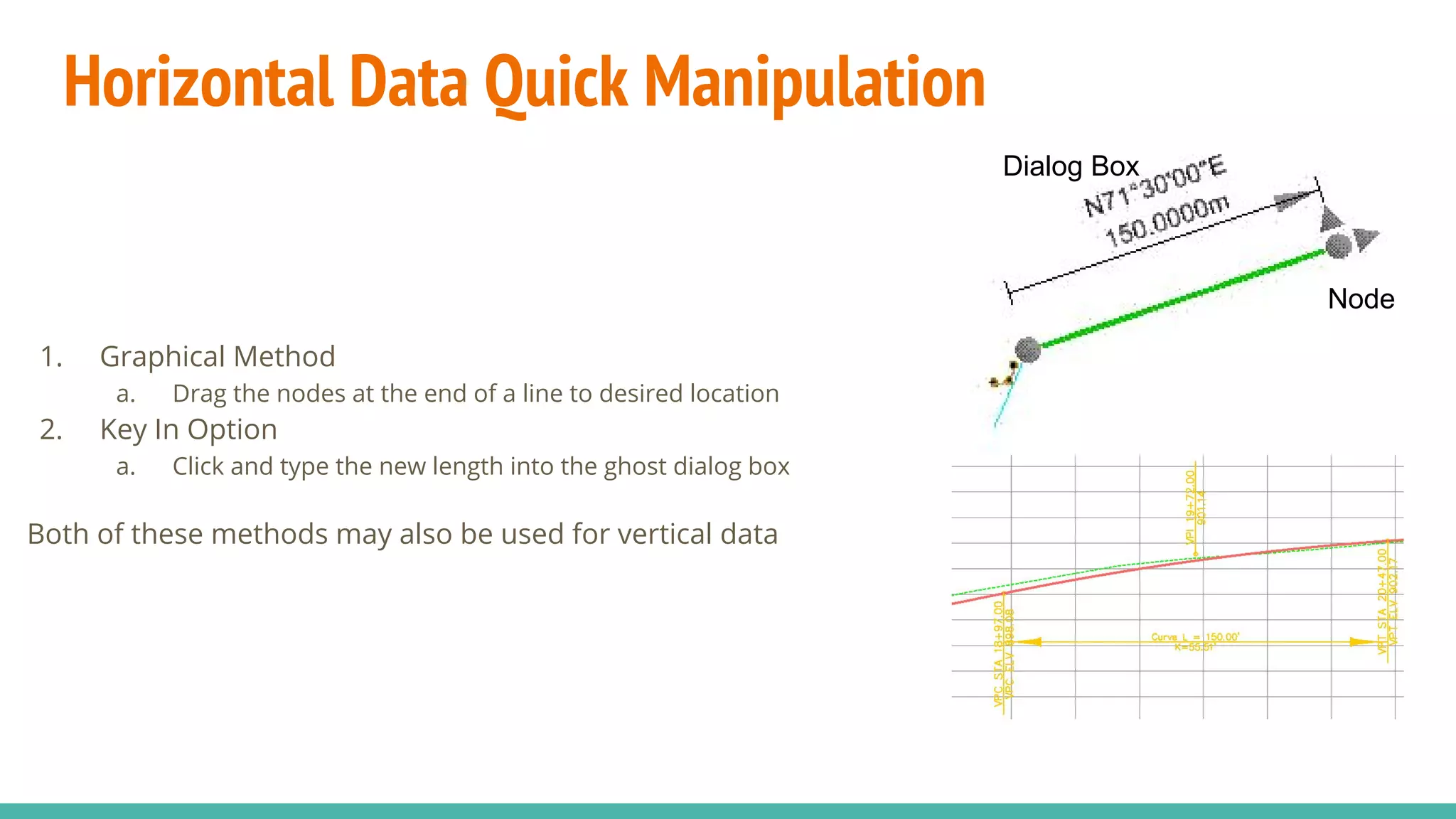
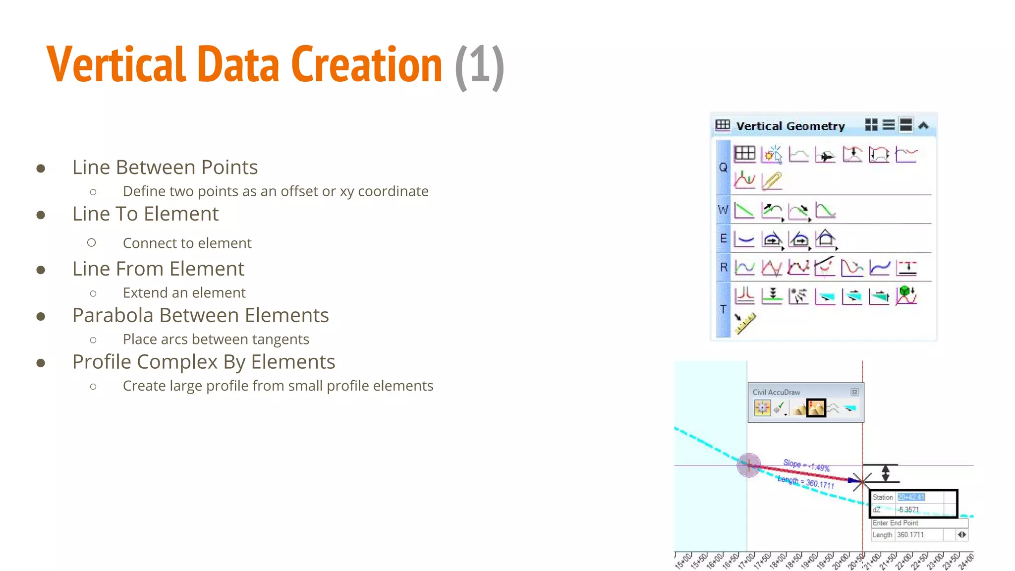
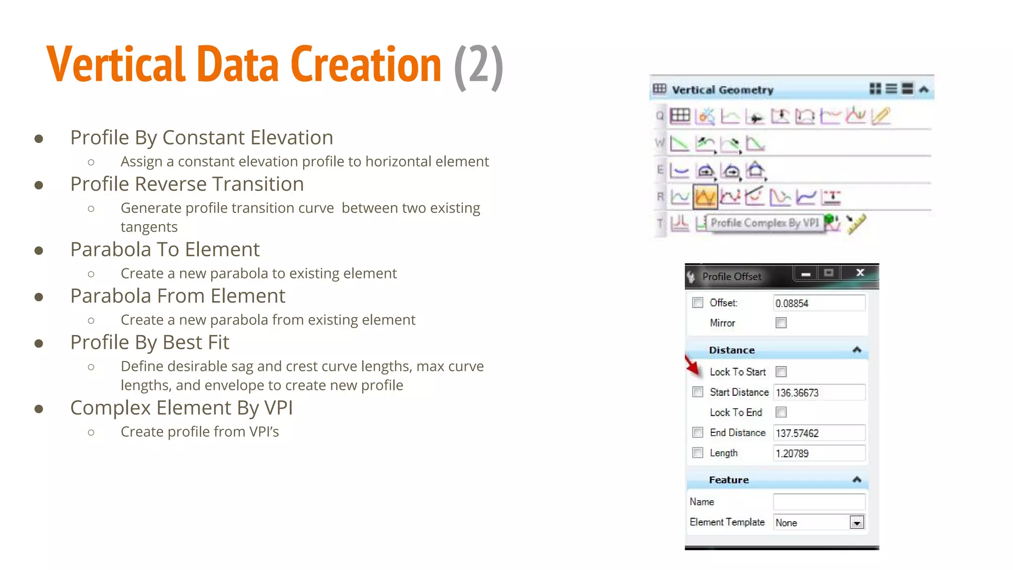
Microstation SS4 Corridor
Modeler: Alignment Data
A guide of components
By: Chris Chatfield, P.E.
Outline
1. Civil AccuDraw
2. Horizontal Data Creation
3. Horizontal Data Quick
Manipulation
4. Vertical Data Creation
5. Vertical Data Projection
6. Alignment Integration
7. Miscellaneous Options
Civil AccuDraw
● Similar to Microstation AccuDraw
○ Defines point in space to start element
○ Can be used in vertical or horizontal views
■ Ensure correct view is active before tool is
started
● Main Methods
○ Station & Offset
○ Delta Station & Offset
○ X & Y
○ Radial Distance/Direction From Point
○ Radial Distance From One Point, Direction From
Another
○ Radial Distance From Two Points
Horizontal Data Creation (1)
● Line Between Points
○ Define two points as an offset or xy coordinate
● Line To Element
○ Connects to an element
● Line From Element
○ Extends an element
● Line Between Arcs
○ Constructs line between two previously made arcs
● Chamfer Between Elements
○ Places line at intersection of two elements
● Circle
○ Creates element from center point and defined radius
● Arc Between Points
○ Create from a variety of methods; including between 3 points
● Simple Arc To Element
○ Constructs arc to pre-existing element via a variety of methods
● Simple Arc From Element
○ Constructs arc from an existing element via a variety of methods
Horizontal Data Creation (2)
● Single Offset Entire Element
○ Applies input offset to create new element
● Add Station Equation
○ Adds a station equation to element
● Start Station
○ Gives a beginning station to element
● Complex By Element
○ Joins multiple elements graphically
● Spiral Between Elements
○ Uses existing elements as tangents to create spiral
● Spiral From Element
○ Create chorded spirals from existing element
● Complex Transition Between Element And Arc
○ Makes back spiral/ ahead transition between element and arc
● Simple Arc
○ Creates various arcs such as taper-arc-taper and spiral-arc-spiral
● Arc Between Arcs
○ Makes arc between two previously created ones
Horizontal Data Creation (3)
● Create Civil Rule
○ Assigns feature definition to an element
● Copy Element
○ Applies offset to create new element
Horizontal - Complex By PI
● Defined By Back and Ahead Transitions
● Type can either be specified as ‘spiral’ or ‘curve’
● Method may be designated as length, ‘A value’,
deflection, delta R, RL, or ratio.
● Choose the PI locations to complete
c
Horizontal- Define Horizontal
By Best Fit
● Used to make alignment from survey
● Make either complex or single element
● Define parameters of the new alignment
● Set feature definition and define name of line
Horizontal-Create Geometry By Template
● Specify the begin/end station and specific template of
proposed element
● Creates a horizontal line in conjunction with any point
set in a template as ‘create geometry’ in its feature
definition.
○ For example, it creates an EOP (Edge of Pavement) line from a
template if the template has an EOP point
Horizontal Data Quick Manipulation
1. Graphical Method
a. Drag the nodes at the end of a line to desired location
2. Key In Option
a. Click and type the new length into the ghost dialog box
Both of these methods may also be used for vertical data
Node
Dialog Box
Vertical Data Creation (1)
● Line Between Points
○ Define two points as an offset or xy coordinate
● Line To Element
○ Connect to element
● Line From Element
○ Extend an element
● Parabola Between Elements
○ Place arcs between tangents
● Profile Complex By Elements
○ Create large profile from small profile elements
Vertical Data Creation (2)
● Profile By Constant Elevation
○ Assign a constant elevation profile to horizontal element
● Profile Reverse Transition
○ Generate profile transition curve between two existing
tangents
● Parabola To Element
○ Create a new parabola to existing element
● Parabola From Element
○ Create a new parabola from existing element
● Profile By Best Fit
○ Define desirable sag and crest curve lengths, max curve
lengths, and envelope to create new profile
● Complex Element By VPI
○ Create profile from VPI’s
Vertical Data Projection
● Quick Profile Transition
○ Define the profile of an element based on the
profiles of the adjoining elements
○ Transition method between adjoining may be
either linear or parabolic
● Profile By Vertical Offset From Element
○ Define the profile of an element based on a
vertical offset
● Profile Intersection Point
○ Connect profiles to each other
■ Automatically updates when main
profile changes
● Quick Profile From Surface
○ Select reference surface and chosen horizontal
alignment to create profile
● Profile By 3D Element
○ Create profile from previously created 3D
element, such as a linear template
● Profile Offset Transition
○ Make new profile as an varied offset from
existing
● Project Profile To Element
○ Copy a profile associated with one horizontal
element to another horizontal element
● Project Profile Range To Element
○ Project profile for a given station range
● Project Extended Profile
○ Connect the profiles of adjacent horizontal
elements
Vertical Data Projection: Profile By Variable Slope
From Element
● Create profile with varied slope relative to
another alignment profile
○ May be used to define an edge of pavement relative to the
center alignment
● Define start and end stations of each unique
segment
● Specify the slope style; the most common style
is linear
● Proposed profile to be defined by linear
template and name
● Use ‘Profile Complex By Elements’ to create
continuous alignment after tool is run
Alignment Integration
● Create corridor based from one main alignment
○ Corridor disappears when main alignment is deleted
● Associate all other alignment data to corridor
○ 2D elements are graphically selected and associated vertical
information is referenced along with it
● Vertical must be selected as ‘active’ in order to
utilize the data
○ Select horizontal element first
■ Blue arrows will appear on the horizontal element
when selected
○ One horizontal line may have multiple associated vertical
alignments
○ Set existing ground terrain model as ‘active’ to utilize its
information
Miscellaneous Options
● Import/Export
○ Able to import *.gpk, *.xml, *.fil, and *.alg
○ Assign feature definition to element after it is imported
○ Able to export a previously created *.gpk
● Reports
○ Customizable Horizontal info may be exported in a variety of formats
with use of ‘Horizontal Geometry Report’ tool
○ Vertical data may also be exported as report with ‘Profile Report’ tool
Sources
http://envisioncad.com
http://communities.bentley.com
http://design.modot.mo.gov/CADD/BentleyCivil/Road_1_Class/Manual/SS4_Chapter_02%20Civil_Geometry.pdf
http://www.fdot.gov/cadd/downloads/documentation/FDOTRDAnd3DM/Files/FDOTRoadwayDesignand3DModeling-Master.pdf

Microstation SS4 Corridor Modeler: Alignment Data

  • 1.
    Microstation SS4 Corridor Modeler:Alignment Data A guide of components By: Chris Chatfield, P.E.
  • 2.
    Outline 1. Civil AccuDraw 2.Horizontal Data Creation 3. Horizontal Data Quick Manipulation 4. Vertical Data Creation 5. Vertical Data Projection 6. Alignment Integration 7. Miscellaneous Options
  • 3.
    Civil AccuDraw ● Similarto Microstation AccuDraw ○ Defines point in space to start element ○ Can be used in vertical or horizontal views ■ Ensure correct view is active before tool is started ● Main Methods ○ Station & Offset ○ Delta Station & Offset ○ X & Y ○ Radial Distance/Direction From Point ○ Radial Distance From One Point, Direction From Another ○ Radial Distance From Two Points
  • 4.
    Horizontal Data Creation(1) ● Line Between Points ○ Define two points as an offset or xy coordinate ● Line To Element ○ Connects to an element ● Line From Element ○ Extends an element ● Line Between Arcs ○ Constructs line between two previously made arcs ● Chamfer Between Elements ○ Places line at intersection of two elements ● Circle ○ Creates element from center point and defined radius ● Arc Between Points ○ Create from a variety of methods; including between 3 points ● Simple Arc To Element ○ Constructs arc to pre-existing element via a variety of methods ● Simple Arc From Element ○ Constructs arc from an existing element via a variety of methods
  • 5.
    Horizontal Data Creation(2) ● Single Offset Entire Element ○ Applies input offset to create new element ● Add Station Equation ○ Adds a station equation to element ● Start Station ○ Gives a beginning station to element ● Complex By Element ○ Joins multiple elements graphically ● Spiral Between Elements ○ Uses existing elements as tangents to create spiral ● Spiral From Element ○ Create chorded spirals from existing element ● Complex Transition Between Element And Arc ○ Makes back spiral/ ahead transition between element and arc ● Simple Arc ○ Creates various arcs such as taper-arc-taper and spiral-arc-spiral ● Arc Between Arcs ○ Makes arc between two previously created ones
  • 6.
    Horizontal Data Creation(3) ● Create Civil Rule ○ Assigns feature definition to an element ● Copy Element ○ Applies offset to create new element
  • 7.
    Horizontal - ComplexBy PI ● Defined By Back and Ahead Transitions ● Type can either be specified as ‘spiral’ or ‘curve’ ● Method may be designated as length, ‘A value’, deflection, delta R, RL, or ratio. ● Choose the PI locations to complete c
  • 8.
    Horizontal- Define Horizontal ByBest Fit ● Used to make alignment from survey ● Make either complex or single element ● Define parameters of the new alignment ● Set feature definition and define name of line
  • 9.
    Horizontal-Create Geometry ByTemplate ● Specify the begin/end station and specific template of proposed element ● Creates a horizontal line in conjunction with any point set in a template as ‘create geometry’ in its feature definition. ○ For example, it creates an EOP (Edge of Pavement) line from a template if the template has an EOP point
  • 10.
    Horizontal Data QuickManipulation 1. Graphical Method a. Drag the nodes at the end of a line to desired location 2. Key In Option a. Click and type the new length into the ghost dialog box Both of these methods may also be used for vertical data Node Dialog Box
  • 11.
    Vertical Data Creation(1) ● Line Between Points ○ Define two points as an offset or xy coordinate ● Line To Element ○ Connect to element ● Line From Element ○ Extend an element ● Parabola Between Elements ○ Place arcs between tangents ● Profile Complex By Elements ○ Create large profile from small profile elements
  • 12.
    Vertical Data Creation(2) ● Profile By Constant Elevation ○ Assign a constant elevation profile to horizontal element ● Profile Reverse Transition ○ Generate profile transition curve between two existing tangents ● Parabola To Element ○ Create a new parabola to existing element ● Parabola From Element ○ Create a new parabola from existing element ● Profile By Best Fit ○ Define desirable sag and crest curve lengths, max curve lengths, and envelope to create new profile ● Complex Element By VPI ○ Create profile from VPI’s
  • 13.
    Vertical Data Projection ●Quick Profile Transition ○ Define the profile of an element based on the profiles of the adjoining elements ○ Transition method between adjoining may be either linear or parabolic ● Profile By Vertical Offset From Element ○ Define the profile of an element based on a vertical offset ● Profile Intersection Point ○ Connect profiles to each other ■ Automatically updates when main profile changes ● Quick Profile From Surface ○ Select reference surface and chosen horizontal alignment to create profile ● Profile By 3D Element ○ Create profile from previously created 3D element, such as a linear template ● Profile Offset Transition ○ Make new profile as an varied offset from existing ● Project Profile To Element ○ Copy a profile associated with one horizontal element to another horizontal element ● Project Profile Range To Element ○ Project profile for a given station range ● Project Extended Profile ○ Connect the profiles of adjacent horizontal elements
  • 14.
    Vertical Data Projection:Profile By Variable Slope From Element ● Create profile with varied slope relative to another alignment profile ○ May be used to define an edge of pavement relative to the center alignment ● Define start and end stations of each unique segment ● Specify the slope style; the most common style is linear ● Proposed profile to be defined by linear template and name ● Use ‘Profile Complex By Elements’ to create continuous alignment after tool is run
  • 15.
    Alignment Integration ● Createcorridor based from one main alignment ○ Corridor disappears when main alignment is deleted ● Associate all other alignment data to corridor ○ 2D elements are graphically selected and associated vertical information is referenced along with it ● Vertical must be selected as ‘active’ in order to utilize the data ○ Select horizontal element first ■ Blue arrows will appear on the horizontal element when selected ○ One horizontal line may have multiple associated vertical alignments ○ Set existing ground terrain model as ‘active’ to utilize its information
  • 16.
    Miscellaneous Options ● Import/Export ○Able to import *.gpk, *.xml, *.fil, and *.alg ○ Assign feature definition to element after it is imported ○ Able to export a previously created *.gpk ● Reports ○ Customizable Horizontal info may be exported in a variety of formats with use of ‘Horizontal Geometry Report’ tool ○ Vertical data may also be exported as report with ‘Profile Report’ tool
  • 17.