Microproccesor Theory_part2 for effective presentation.pptx
1.
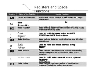
8086
registers
categorized
into 4
groups
Registers, Flag
150
15
BIU
0
1 General
purpose
register
16 bit
8 bit
16
bit
16 bit
2 Pointer register
3 Index register
4 Instruction
Pointer
5 Segment register
16
bit
16 bit
6 Flag
(PSW)
16
bit
IS 14 13 12 11 10
9
8 7 6 S 4 3 2 1
0
AX, BX, CX, DX
AL, AH, BL, BH, CL, CH, DL, DH
SP, BP
SI,DI
Z
P
CS,DS
,SS,ES
Flag
register
instruction Queue
62
& 8086employs parallel processing
• When EU is busy decoding or executing
current instruction, the buses of 8086
may not be in use.
& At that time, BIU can use buses to fetch
upto six instruction bytes for the
following instructions
& BIU stores these pre-fetched bytes in a
FIF!? register called Instruction Queue
• When EU is ready for its next instruction,
it simply reads the instruction from the
queue in BIU
5.
&EU of 8086does not have to
wait in between for BIU to fetch
next instruction byte from
memory
63
&So the presence of a queue in
8086 speeds up the processing
& Fetching the next instruction while
the current instruction executes is
called pipelining
6.
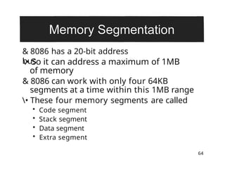
& 8086 hasa 20-bit address
bus
64
• So it can address a maximum of 1MB
of memory
& 8086 can work with only four 64KB
segments at a time within this 1MB range
• These four memory segments are called
• Code segment
• Stack segment
• Data segment
• Extra segment
• That partof memory from where BIU
is currently fetching instruction code
bytes
66
¥• A section of memory set aside to
store addresses and data while a
subprogram executes
• Used for storing data values to be used
in the program
& hold theupper 16-bits of the
starting address for each of the
segments
&The four segment registers are
68
• CS (Code Segment register)
• DS (Data Segment register)
• SS (Stack Segment register)
• ES (Extra Segment register)
11.
DS
ES 000
0H
SS FAO0 0H
Memory
1
0
12
14
15
00000H
1MB
Address
Range
FFFFFH 6g
12.
70
&Address of asegment is of 20-bits
&A segment register stores only upper
16- bits
& BIU always inserts zeros for the
lowest 4-
bits of the 20-bit starting address.
& E.g. if CS = 348AH, then the code
segment will start at 348A0H
&A 64-KB segment can be located
anywhere in the memory, but will staJ
at an address with zeros in the lowest
4-bits
13.
&a 16-bit
register
71
& Holds16-bit offset, of the next
instruction
byte in the code segment
& BIU uses IP and CS registers to
generate the 20-bit address of the
instruction to be fetched from
memory
14.
Physical Address
CalculatiOn
g,te„,O
1
Daa
Segment
3
Start ofCode
Segment
348A0H
—•
IP = 4214H
Code Byte 38AB4H
OOOO
H
cs
348A0H
IP
+4214H
PhysicalAddress38›tB4 H
4
Code
Segmen
t
Extra
Segment
7
8
9
10
11
12
13
14
15
Stack
Segmen
t
1
M
B
Addres
s
Range
FFFFi7H
15.
Stack Segment (SS)
RegisterStack Pointer
(SPj Registers
73
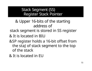
& Upper 16-bits of the starting
address of
stack segment is stored in SS register
& It is located in BIU
&SP register holds a 16-bit offset from
the staJ of stack segment to the top
of the stack
& It is located in EU
16.
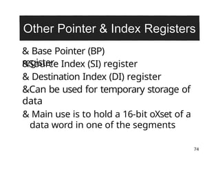
& Base Pointer(BP)
register
74
&Source Index (SI) register
& Destination Index (DI) register
&Can be used for temporary storage of
data
& Main use is to hold a 16-bit oXset of a
data word in one of the segments