This document provides instructions for removing and installing an engine. Key steps include:
- Removing accessories, hoses, wiring harnesses, and other components to fully separate the engine from the vehicle
- Using special tools and hoists to lift and support the engine/transmission assembly
- Removing the subframe and other components to create enough clearance to remove the engine
- Reinstalling components in reverse order, torquing all fasteners to specification and reconnecting all electrical, fuel, and cooling components.
This is the Highly Detailed factory service repair manual for the2007 HONDA CRV, this Service Manual has detailed illustrations as well as step by step instructions,It is 100 percents complete and intact. they are specifically written for the do-it-yourself-er as well as the experienced mechanic.2007 HONDA CRV Service Repair Workshop Manual provides step-by-step instructions based on the complete dis-assembly of the machine. It is this level of detail, along with hundreds of photos and illustrations, that guide the reader through each service and repair procedure. Complete download comes in pdf format which can work under all PC based windows operating system and Mac also, All pages are printable. Using this repair manual is an inexpensive way to keep your vehicle working properly.
Service Repair Manual Covers:
General Information
Specifications
Maintenance
Engine Electrical
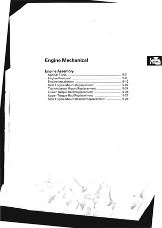
Engine Mechanical
Engine Cooling
Fuel and Emissions
Transaxle
Steering
Suspension
Brakes
Body
Heating
Ventilations
Air Conditioning
Body Electrical
Audio
Navigation
Telematics
Restraints
File Format: PDF
Compatible: All Versions of Windows & Mac
Language: English
Requirements: Adobe PDF Reader
NO waiting, Buy from responsible seller and get INSTANT DOWNLOAD, Without wasting your hard-owned money on uncertainty or surprise! All pages are is great to have2007 HONDA CRV Service Repair Workshop Manual.
Looking for some other Service Repair Manual,please check:
https://www.aservicemanualpdf.com/
Thanks for visiting!
8
This is the Highly Detailed factory service repair manual for the2008 HONDA CRV, this Service Manual has detailed illustrations as well as step by step instructions,It is 100 percents complete and intact. they are specifically written for the do-it-yourself-er as well as the experienced mechanic.2008 HONDA CRV Service Repair Workshop Manual provides step-by-step instructions based on the complete dis-assembly of the machine. It is this level of detail, along with hundreds of photos and illustrations, that guide the reader through each service and repair procedure. Complete download comes in pdf format which can work under all PC based windows operating system and Mac also, All pages are printable. Using this repair manual is an inexpensive way to keep your vehicle working properly.
Service Repair Manual Covers:
General Information
Specifications
Maintenance
Engine Electrical
Engine Mechanical
Engine Cooling
Fuel and Emissions
Transaxle
Steering
Suspension
Brakes
Body
Heating
Ventilations
Air Conditioning
Body Electrical
Audio
Navigation
Telematics
Restraints
File Format: PDF
Compatible: All Versions of Windows & Mac
Language: English
Requirements: Adobe PDF Reader
NO waiting, Buy from responsible seller and get INSTANT DOWNLOAD, Without wasting your hard-owned money on uncertainty or surprise! All pages are is great to have2008 HONDA CRV Service Repair Workshop Manual.
Looking for some other Service Repair Manual,please check:
https://www.aservicemanualpdf.com/
Thanks for visiting!
This is the Highly Detailed factory service repair manual for the2009 HONDA CRV, this Service Manual has detailed illustrations as well as step by step instructions,It is 100 percents complete and intact. they are specifically written for the do-it-yourself-er as well as the experienced mechanic.2009 HONDA CRV Service Repair Workshop Manual provides step-by-step instructions based on the complete dis-assembly of the machine. It is this level of detail, along with hundreds of photos and illustrations, that guide the reader through each service and repair procedure. Complete download comes in pdf format which can work under all PC based windows operating system and Mac also, All pages are printable. Using this repair manual is an inexpensive way to keep your vehicle working properly.
Service Repair Manual Covers:
General Information
Specifications
Maintenance
Engine Electrical
Engine Mechanical
Engine Cooling
Fuel and Emissions
Transaxle
Steering
Suspension
Brakes
Body
Heating
Ventilations
Air Conditioning
Body Electrical
Audio
Navigation
Telematics
Restraints
File Format: PDF
Compatible: All Versions of Windows & Mac
Language: English
Requirements: Adobe PDF Reader
NO waiting, Buy from responsible seller and get INSTANT DOWNLOAD, Without wasting your hard-owned money on uncertainty or surprise! All pages are is great to have2009 HONDA CRV Service Repair Workshop Manual.
Looking for some other Service Repair Manual,please check:
https://www.aservicemanualpdf.com/
Thanks for visiting!
8
This is the Highly Detailed factory service repair manual for the2007 HONDA CRV, this Service Manual has detailed illustrations as well as step by step instructions,It is 100 percents complete and intact. they are specifically written for the do-it-yourself-er as well as the experienced mechanic.2007 HONDA CRV Service Repair Workshop Manual provides step-by-step instructions based on the complete dis-assembly of the machine. It is this level of detail, along with hundreds of photos and illustrations, that guide the reader through each service and repair procedure. Complete download comes in pdf format which can work under all PC based windows operating system and Mac also, All pages are printable. Using this repair manual is an inexpensive way to keep your vehicle working properly.
Service Repair Manual Covers:
General Information
Specifications
Maintenance
Engine Electrical
Engine Mechanical
Engine Cooling
Fuel and Emissions
Transaxle
Steering
Suspension
Brakes
Body
Heating
Ventilations
Air Conditioning
Body Electrical
Audio
Navigation
Telematics
Restraints
File Format: PDF
Compatible: All Versions of Windows & Mac
Language: English
Requirements: Adobe PDF Reader
NO waiting, Buy from responsible seller and get INSTANT DOWNLOAD, Without wasting your hard-owned money on uncertainty or surprise! All pages are is great to have2007 HONDA CRV Service Repair Workshop Manual.
Looking for some other Service Repair Manual,please check:
https://www.aservicemanualpdf.com/
Thanks for visiting!
8
This is the Highly Detailed factory service repair manual for the2008 HONDA CRV, this Service Manual has detailed illustrations as well as step by step instructions,It is 100 percents complete and intact. they are specifically written for the do-it-yourself-er as well as the experienced mechanic.2008 HONDA CRV Service Repair Workshop Manual provides step-by-step instructions based on the complete dis-assembly of the machine. It is this level of detail, along with hundreds of photos and illustrations, that guide the reader through each service and repair procedure. Complete download comes in pdf format which can work under all PC based windows operating system and Mac also, All pages are printable. Using this repair manual is an inexpensive way to keep your vehicle working properly.
Service Repair Manual Covers:
General Information
Specifications
Maintenance
Engine Electrical
Engine Mechanical
Engine Cooling
Fuel and Emissions
Transaxle
Steering
Suspension
Brakes
Body
Heating
Ventilations
Air Conditioning
Body Electrical
Audio
Navigation
Telematics
Restraints
File Format: PDF
Compatible: All Versions of Windows & Mac
Language: English
Requirements: Adobe PDF Reader
NO waiting, Buy from responsible seller and get INSTANT DOWNLOAD, Without wasting your hard-owned money on uncertainty or surprise! All pages are is great to have2008 HONDA CRV Service Repair Workshop Manual.
Looking for some other Service Repair Manual,please check:
https://www.aservicemanualpdf.com/
Thanks for visiting!
This is the Highly Detailed factory service repair manual for the2009 HONDA CRV, this Service Manual has detailed illustrations as well as step by step instructions,It is 100 percents complete and intact. they are specifically written for the do-it-yourself-er as well as the experienced mechanic.2009 HONDA CRV Service Repair Workshop Manual provides step-by-step instructions based on the complete dis-assembly of the machine. It is this level of detail, along with hundreds of photos and illustrations, that guide the reader through each service and repair procedure. Complete download comes in pdf format which can work under all PC based windows operating system and Mac also, All pages are printable. Using this repair manual is an inexpensive way to keep your vehicle working properly.
Service Repair Manual Covers:
General Information
Specifications
Maintenance
Engine Electrical
Engine Mechanical
Engine Cooling
Fuel and Emissions
Transaxle
Steering
Suspension
Brakes
Body
Heating
Ventilations
Air Conditioning
Body Electrical
Audio
Navigation
Telematics
Restraints
File Format: PDF
Compatible: All Versions of Windows & Mac
Language: English
Requirements: Adobe PDF Reader
NO waiting, Buy from responsible seller and get INSTANT DOWNLOAD, Without wasting your hard-owned money on uncertainty or surprise! All pages are is great to have2009 HONDA CRV Service Repair Workshop Manual.
Looking for some other Service Repair Manual,please check:
https://www.aservicemanualpdf.com/
Thanks for visiting!
8
Core technology of Hyundai Motor Group's EV platform 'E-GMP'Hyundai Motor Group
What’s the force behind Hyundai Motor Group's EV performance and quality?
Maximized driving performance and quick charging time through high-density battery pack and fast charging technology and applicable to various vehicle types!
Discover more about Hyundai Motor Group’s EV platform ‘E-GMP’!
"Trans Failsafe Prog" on your BMW X5 indicates potential transmission issues requiring immediate action. This safety feature activates in response to abnormalities like low fluid levels, leaks, faulty sensors, electrical or mechanical failures, and overheating.
Ever been troubled by the blinking sign and didn’t know what to do?
Here’s a handy guide to dashboard symbols so that you’ll never be confused again!
Save them for later and save the trouble!
Symptoms like intermittent starting and key recognition errors signal potential problems with your Mercedes’ EIS. Use diagnostic steps like error code checks and spare key tests. Professional diagnosis and solutions like EIS replacement ensure safe driving. Consult a qualified technician for accurate diagnosis and repair.
What Does the PARKTRONIC Inoperative, See Owner's Manual Message Mean for You...Autohaus Service and Sales
Learn what "PARKTRONIC Inoperative, See Owner's Manual" means for your Mercedes-Benz. This message indicates a malfunction in the parking assistance system, potentially due to sensor issues or electrical faults. Prompt attention is crucial to ensure safety and functionality. Follow steps outlined for diagnosis and repair in the owner's manual.
What Exactly Is The Common Rail Direct Injection System & How Does It WorkMotor Cars International
Learn about Common Rail Direct Injection (CRDi) - the revolutionary technology that has made diesel engines more efficient. Explore its workings, advantages like enhanced fuel efficiency and increased power output, along with drawbacks such as complexity and higher initial cost. Compare CRDi with traditional diesel engines and discover why it's the preferred choice for modern engines.
5 Warning Signs Your BMW's Intelligent Battery Sensor Needs AttentionBertini's German Motors
IBS monitors and manages your BMW’s battery performance. If it malfunctions, you will have to deal with an array of electrical issues in your vehicle. Recognize warning signs like dimming headlights, frequent battery replacements, and electrical malfunctions to address potential IBS issues promptly.
𝘼𝙣𝙩𝙞𝙦𝙪𝙚 𝙋𝙡𝙖𝙨𝙩𝙞𝙘 𝙏𝙧𝙖𝙙𝙚𝙧𝙨 𝙞𝙨 𝙫𝙚𝙧𝙮 𝙛𝙖𝙢𝙤𝙪𝙨 𝙛𝙤𝙧 𝙢𝙖𝙣𝙪𝙛𝙖𝙘𝙩𝙪𝙧𝙞𝙣𝙜 𝙩𝙝𝙚𝙞𝙧 𝙥𝙧𝙤𝙙𝙪𝙘𝙩𝙨. 𝙒𝙚 𝙝𝙖𝙫𝙚 𝙖𝙡𝙡 𝙩𝙝𝙚 𝙥𝙡𝙖𝙨𝙩𝙞𝙘 𝙜𝙧𝙖𝙣𝙪𝙡𝙚𝙨 𝙪𝙨𝙚𝙙 𝙞𝙣 𝙖𝙪𝙩𝙤𝙢𝙤𝙩𝙞𝙫𝙚 𝙖𝙣𝙙 𝙖𝙪𝙩𝙤 𝙥𝙖𝙧𝙩𝙨 𝙖𝙣𝙙 𝙖𝙡𝙡 𝙩𝙝𝙚 𝙛𝙖𝙢𝙤𝙪𝙨 𝙘𝙤𝙢𝙥𝙖𝙣𝙞𝙚𝙨 𝙗𝙪𝙮 𝙩𝙝𝙚 𝙜𝙧𝙖𝙣𝙪𝙡𝙚𝙨 𝙛𝙧𝙤𝙢 𝙪𝙨.
Over the 10 years, we have gained a strong foothold in the market due to our range's high quality, competitive prices, and time-lined delivery schedules.
In this presentation, we have discussed a very important feature of BMW X5 cars… the Comfort Access. Things that can significantly limit its functionality. And things that you can try to restore the functionality of such a convenient feature of your vehicle.
Comprehensive program for Agricultural Finance, the Automotive Sector, and Empowerment . We will define the full scope and provide a detailed two-week plan for identifying strategic partners in each area within Limpopo, including target areas.:
1. Agricultural : Supporting Primary and Secondary Agriculture
• Scope: Provide support solutions to enhance agricultural productivity and sustainability.
• Target Areas: Polokwane, Tzaneen, Thohoyandou, Makhado, and Giyani.
2. Automotive Sector: Partnerships with Mechanics and Panel Beater Shops
• Scope: Develop collaborations with automotive service providers to improve service quality and business operations.
• Target Areas: Polokwane, Lephalale, Mokopane, Phalaborwa, and Bela-Bela.
3. Empowerment : Focusing on Women Empowerment
• Scope: Provide business support support and training to women-owned businesses, promoting economic inclusion.
• Target Areas: Polokwane, Thohoyandou, Musina, Burgersfort, and Louis Trichardt.
We will also prioritize Industrial Economic Zone areas and their priorities.
Sign up on https://profilesmes.online/welcome/
To be eligible:
1. You must have a registered business and operate in Limpopo
2. Generate revenue
3. Sectors : Agriculture ( primary and secondary) and Automative
Women and Youth are encouraged to apply even if you don't fall in those sectors.
Things to remember while upgrading the brakes of your carjennifermiller8137
Upgrading the brakes of your car? Keep these things in mind before doing so. Additionally, start using an OBD 2 GPS tracker so that you never miss a vehicle maintenance appointment. On top of this, a car GPS tracker will also let you master good driving habits that will let you increase the operational life of your car’s brakes.
Why Is Your BMW X3 Hood Not Responding To Release CommandsDart Auto
Experiencing difficulty opening your BMW X3's hood? This guide explores potential issues like mechanical obstruction, hood release mechanism failure, electrical problems, and emergency release malfunctions. Troubleshooting tips include basic checks, clearing obstructions, applying pressure, and using the emergency release.
3. Engine Removal
Special Tools Required
• Universal eyelet 07AAK-SNAA120
• Engine hanger adapter VSB02C000015 *
• Front subframe adapter VSB02C000016 *
• CR-V engine hanger adapter VSB02C000032 *
• Engine support hanger, A and Reds AAR-T-12566 *
*:Available through American Honda Tool and
Equipment Program, 1-888-424-6857
NOTE:
• Use fender covers to avoid damaging painted
surfaces.
• To avoid damaging the wiring and terminals, unplug
the wiring connectors carefully while holding the
connector portion.
• Mark all wiring and hoses to avoid misconnection.
Also, be sure that they do not contact other wiring or
hoses, or interfere w ith other parts.
1. Make sure you have the anti-theft code for the
audio system and the navigation system (if
equipped), then write down the XM radio presets.
2. Remove the hood support rod, then use it as shown
to prop the hood in the wide-open position.
3. Relieve the fuel pressure (see page 11-317).
4. Disconnect the negative cable from the battery fi rst,
then disconnect the positive cable.
5. Remove the battery.
6. Remove the air cleaner housing assembly
(see page 11-340).
7. Remove the harness clamp (A) and ground cable
(B).
8. Remove the battery cables (A) from the under-hood
fuse/relay box.
9. Disconnect the harness connector (8), and remove
the harness clamp (C).
(cont'd)
5-3
4. Engine Assembly
Engine Removal (cont'd)
10. Remove the powertrain control module (peM)
cover (A), then remove the three bolts (8) securing
the peM.
11. Disconnect the peM connectors (A) and the engine
wire harness connector (8).
B
12. Remove the harness clamps (e).
13. Remove the harness clamp (A), then remove the
peM bracket (8).
14. Remove the evaporative emission (EVAP) canister
hose (A) and brake booster vacuum hose (8).
5-4
5. 15. Remove the quick-connect fitting cover (A), then
disconnect the fuel feed hose (see page 11-324).
A
16. Remove the drive belt (see page 4-29).
17. Remove the power steering (PIS) pump (A) without
disconnecting the PIS hoses, then remove the PIS
hose from the clamp (8).
18. Remove the radiator cap.
19. Raise the vehicle on the lift to full height.
20. Remove the front wheels.
21. Remove the splash shield.
22. Loosen the drain plug in the radiator, and drain the
engine coolant (see page 10-6).
23. Drain the engine oil (see page 8-10).
24. Drain the automatic transmission fluid (ATF)
(see page 14-239).
25. Disconnect the air fuel ratio (A/F) sensor connector
(A) and secondary heated oxygen sensor
(secondary H02S) connector (8).
A
26. Remove the three way catalytic converter (lWC) (C).
(cont'd)
5-5
6. I "
Engine Assembly
Engine Removal (cont'd)
27, Remove the shift cable (see step 34 on page
14-251).
28. Separate the knuckles from the lower arms
(see page 18-12).
29. Remove the driveshafts (see step 7 on page 16-5).
Coat all precision-finished surfaces with clean
engine oil. Tie plastic bags over the driveshaft ends.
30. Remove the propeller shaft (see page 16-40).
31 . Remove the bolt (A) securing the PIS fluid line
bracket, and unclamp the PIS fluid line clamps (B)
on the front subframe.
B
.1
32. Remove the bolts securing the left steering gearbox
mounting bracket.
33. Remove the bolts securing the right steering
gearbox mounting brackets.
5-6
7. r
34. Disconnect the AlC compressor clutch connector
(A), then remove the AlC compressor (8) without
disconnecting the AlC hoses.
A
35. Lower the vehicle on the lift.
36. Remove the radiator (see page 10-18).
37. Remove the ATF cooler hose, then plug the line and
hose.
38. Remove the heater hoses.
39. Install the front bulkhead (see step 16 on page
10-20).
40. Attach the special tool adapter (VS802C000015) to
the threaded hole (A) in the cylinder head.
(cont'd)
5-7
8. Engine Assembly
Engine Removal (cont'd)
41. Remove both lids (A) from the cowl cover. Position
the engine hanger adapters (VSB02C000032) over
the damper flange nuts.
42. Install the engine support hanger (AAR-T-12566),
then attach the hook to the slotted hole in the
hanger adapter. Tighten the wing nut (A) by hand to
lift and support the engine/transmission assembly.
NOTE: Be careful when working around the
windshield.
AAR-T-12566
43. Raise the lift to full height. , '
44. Remove the lower torque rod.
Replace.
45. Make the appropriate reference lines (A) at both
ends of the subframe that line up with the body (B).
A A
5-8
9. 46. Remove the subframe mounting bolts (A) on both
sides.
47. Attach the subframe adapter (A) to the subframe
and hang the belt of the subframe adapter over the
front of the subframe, then secure the belt with its
stop.
A
VSB02C000016
48. Raise the jack and line up the slots in the arms with
the bolt holes on the corner of the jack base, then
attach them with bolts securely.
49. Remove the subframe.
Replace.
50. Lower the vehicle on the lift.
51. Remove the transmission mount.
Replace.
J
Replace.
(cont'd)
5-9
10. Engine Assembly
Engine Removal (cont'd)
52. Remove the ground cable (A), then remove the
transmission mount bracket (B).
53. Install the transmission hanger bracket (PIN 21232
RCT-AOO) (A) and washer (B) on the transmission.
54. Install the universal eyelet.
55. Attach a chain hoist (A) to the universal eyelet (B),
and the transmission hook (C). Lift up on the engine
Itransmission assembly until it's securely
supported by the chain hoist, and remove the
engine support hanger.
5-10
11. 56. Remove the side engine mount bracket mounting
bolt and nut.
57. Check that the engine/transmission is completely
free of vacuum hoses, fuel and coolant hoses, and
electrical wiring.
58. Slowly lower the engine/transmission assembly
about 150 mm (6 in.). Check once again that all
hoses and electrical wiring are disconnected and
free from the engine/transmission, then lower it all
the way.
59. Disconnect the chain hoist from the engine/
transmission assembly.
60. Raise the vehicle all the way on the hoist, and
remove the engine/transmission assembly from
under the vehicle.
5-11
12. Engine Assembly
Engine Installation
Special Tools Required
• Universal eyelet 07AAK-SNAA120
• Engine hanger adapter VSB02C000015 *
• Front subframe adapter VSB02C000016 *
• CR-V engine hanger adapter VSB02C000032 *
• Engine support hanger, A and Reds AAR-T-12566 *
*:Available through American Honda Tool and Equipment Program, 1-888-424-6857
1. Install the accessory brackets, and tighten their bolts to the specified torques.
SIDE ENGINE MOUNT BRACKET
10x1.25mm
44 N·m 14.5 kgf·m,
12 x 1.25 mm
81 N·m 18.3 kgf·m.
lOx 1.25 mm
44 N·m (4.5 kgf·m.
33lbf·ftl
33lbf·ftl
60lbf·ftl
Replace.
AIC COMPRESSOR BRACKET
5-12
13. 2. Raise the vehicle on the lift, and position the engine
/transmission assembly under the vehicle. Lower
the vehicle, and attach the specia'tool and chain
hoist to the engine, then lift the engine into position
in the vehicle.
NOTE: Reinstall the mounting bolts and support
nuts in the sequence given in the following steps.
Failure to follow this sequence may cause
excessive noise and vibration, and reduce engine
mount life.
3. Attach the special tool adapter (VSB02C000015) to
the threaded hole (A) in the cylinder head.
4. Remove both lids (A) from the cowl cover. Position
the engine hanger adapters (VSB02C000032) over
the damper flange nuts.
A
VSB02CO00032
5. Install the engine support hanger (AAR-T-12566),
then attach the hook to the slotted hole in the
hanger adapter. Tighten the wing nut (A) by hand to
lift and support the engine/transmission assembly.
NOTE: Be careful when working around the
windshield.
(cont'd)
5..13
14. Engine Assembly
Engine Installation (cont'd)
6. Loosen the upper torque rod mounting bolt (A).
, ' ,
7. Tighten the new side engine mount bracket
mounting bolt and nut.
14x 1.5 mm
74 N·m 7 .5 kgf·m, 54Ibf·ft)
Replace.
8. Remove the chainrhoist
9. Remove the universal eyelet.
10. Remove the transmission hanger bracket (PIN
21232-RCT-AOO) (A) and washer (B).
A
5-14
15. 11. Install the transmission mount bracket (A). then
install the ground cable (B).
6x1.0mm
9.8N·m
11.0kim,7'2Ibf.ftl
/
12. Install the transmission mount, then tighten the
transmission mount stiffener mounting bolts (A)
and the new transmission mount mounting bolts
(B).
B
12 x 1.25 mm
64N·m
(6.5 kgf·m, 47 Ibf·ft)
Replace.
C
12x 1.25 mm
74 N·m (7.5 kgf·m, 54Ibf·ft)
Replace.
13. Tighten the new bolt and nuts (e).
,.
14. Raise the vehicle on the lift to full height.
. ,
15. Using the subframe adapter (A) and a jack, raise
the subframe up to body.
A
VSB02C000016
16. Loosely install the new 14 x 1.5 mm bolts.
14x 1.5 mm
103 N·m (10.5 kgf·m, 76Ibf.ft)
Replace.
(cont'd)
5-15
16. Engine Assembly
Engine Installation (cont'd)
17. Align all reference marks (A) on the front subframe
(8) with the body, then tighten the bolts on the front
subframe to the specified torque.
A A
18. Tighten the new subframe mounting bolts (A) on
both side.
12 x 1.25 mm
64 N·m (6.5 kgf·m. 47 Ibf·ftl
Replace.
19. Install the lower torque rod, then tighten the new
lower torque rod mouhting bolts in the numbered
sequence shown.
® 14x 1.5mm
93N·m
(9.5 kgf·m. 69lbf·ftl
Replace.
CD 12 x 1.25 mm
88 N·m (9.0 kgf·m. 65 Ibf·ftl
Replace.
20. Lower the vehicle on the lift.
21 . Remove the engine support hanger from the
vehicle. Remove the adapter from the cylinder
head.
22. Tighten the upper torque rod mounting bolt.
12 x 1.25 mm
54 N·m (5.5 kgf·m. 40 Ibf.ftl
5-16
17. 23. Raise the vehicle on the lift to full height.
24. Install the AlC compressor (A), then connect the
AlC compressor clutch connector (B).
B
/ A
8x 1.25mm
22 N·m (2.2 kgf.m. 16Ibf·ft)
25. Install the bolts securing the left tsteering gearbox
mounting bracket.
10Xl.25mm
59N·m
/ (6.0 kgf.m. 43 Ibf·ft)
A
. J
26. Install the bolts securing the right steering gearbox
mounting bracket.
(6.0 kgf·m. 43 Ibf·ft)
, /
lOx 1.25 mm
59N·m
27. Install the power steering (PIS) fluid line bracket (A).
and secure the hose with the hose clamps (B).
6x 1.0mm
B 9.8N·m
(1.0 kgf·m. 7.2Ibf·ft)
I
28. Install the propeller shaft (see page 16-41).
29. Install a new set ring on the end of each driveshaft,
then install the driveshafts. Make sure each ring
"clicks" into place in the differential and
intermediate shaft.
30. Connect the lower arms to the knuckles (see step 8
on page 18-20). .
31. Install the shift cable (see step 34 on page 14-262).
(cont'd)
5..17
18. Engine Assembly
Engine Installation (cont'd)
32. Install the three way catalytic converter (lWC) (A).
Use new gaskets (8) and new self-locking nuts (C).
@~ rox 1.25 mm
33N·m
(3.4kgf.m,
25Ibf·ft)
Replace.
o
A E
----- 8 x 1.25 mm
24 N·m 12.4 kgf·m,17 Ibf·ftl
33. Connect the air fuel ratio (NF) sensor connector (0)
and secondary heated oxygen sensor (secondary
H02S) connector (E).
34. Install the splash shield.
35. Lower the vehicle on the lift.
36. Install the heater hoses.
37. Install the radiator (see page 10-18).
38. Install the automatic transmission fluid (ATF) cooler
hose (A), and secure the hoses with the clip (8)
(see page 14-270).
5-18
19. 42. Install the evaporative emission (EVAP) canister
the clamp (8).
39. Install the PIS pump (A), then install the PIS hose to
hose (A) and brake booster vacuum hose (8).
43. Install the powertrain control module (PCM) bracket
(A), then install the harness clamp (8).
6x 1.0mm
9.8 N·m (1 .0 kgf·m. 7.2Ibf·ftl
B
(cont'd)
5-19
8x 1.25 mm
22 N·m (2.2 kgf·m, 16lbf·ftl
40. Install the drive belt (see page 4-29).
41. Connect the fuel feed hose (see page 11-326), then
install the quick-connect fitting cover (A).
A
20. Engine Assembly
Engine Installation (cont'd)
44. Connect the PCM connectors (A) and engine wire 47. Instal! the battery cables (A) to the under-hood
harness connector (8). fuse/relay box.
B
45. Install the harness clamps (C).
46. Install the PCM (A), then install the PCM cover (8).
48. Connect the harness connector (8), and install the
harness clamp (C).
49. Install the ground cable (A) and harness clamp (8).
6x 1.0mm
9.
11
8N·m
.,m.7.2 Ibl·ftl
B
6x 1.0mm
9.8 N·m 11.0 kgf·m, 7.2Ibf·ft)
5-20
21. 50. Install the air cleaner housing assembly (see page
11-340).
51. Install the front wheels.
52. Install the battery. Clean the battery posts and
cable terminals with a battery post cleaner, then
assemble them, and apply grease to prevent
corrosion.
53. Move the shift lever to each gear, and verify that
the A{f gear position indicator follows the
transmission range -switch.
54. Inspect for fuel leaks: Turn the ignition switch ON
(II) (do not operate the starter) so the fuel pump
runs for about 2 seconds and pressurizes the fuel
line. Repeat this operation two or three times, then
check for fuel leakage at any point in the fuel line.
55. Refill the engine with engine oil (see step 4 on page
8-10).
56. Refill the transmission with ATF (see step 3 on page
14-239).
57. Refill the radiator with engine coolant, and bleed
airfrom the cooling system with the heater valve
open (see step 6 on page 10-6).
58. Do the PCM reset procedure (see page 11-4).
59. Do the crankshaft position (CKP) pattern clear/CKP
pattern learn procedure (see page 11-4).
60. Inspect the idle speed (see page 11-303).
61. Inspect the ignition timing (see page 4-18).
62. Check the wheel alignment (see page 18-5).
63. Enter the anti-theft code for the audio system and
the navigation system (if equipped), then enter the
MX radio presets.
64. Set the clock.
5-21
22. A
(1.0 kgf·m. 7.2Ibf.ft)
I 0
,"""ylJ..,U/ ____I
~
Engine Assembly
Side Engine Mount Replacement
, . Support the engine with a jack and wood block
under the oil pan.
2. Remove the power steering (PIS) fluid reservoir
from the holder.
3. Remove the upper torque rod.
4. Remove the ground cable (A), then remove the side
engine mount bracket (B).
5. Remove the side engine mount stiffener (A), then
remove the side engine mount (B).
12 x 1.25 mm 12 x 1.25 mm
57 N·m (5.8 kgf·m. 42 Ibf.ft) 64 N·m
(6.5 kgf·m, 47lbf·ftl
~ 6x 1.0 mm
9.8N·m
. . 11.0 ,.m.7.21bf·ftl
A B
6. Install the side engine mount, then install the side
engine mount stiffener.
7. Install the side engine mount bracket (A), then
loosely tighten the new bolt and nut (BI, and
loosely tighten the bolt (C).
6x 1.0mm
9.8N·m
8. Install the ground cable (D).
5-22
23. t f
9. Remove the air.cleaner housing assembly
(see page 11-340).
10. Loosen the transmission mounting bolt and nuts
(A).
A
11. Raise the lift to full height.
12. Loosen the lower torque rod mounting bolt (A).
A
# •
13. Lower the vehicle on the lift.
14. Tighten the side engine mount mounting bolts and
nut.
12 x 1.25 mm
72N·m
14x 1.5mm
74N·m
(7.3 kgf.m. 52Ibf·ft)
(7.5 kgf.m, 54 Ibf·ft)
15. Tighten the transmission mounting bolt and nuts.
12x 1.25 mm
74 N·m (7.5 kgf.m, 54Ibf·ft)
16. Raise the lift to full height.
(cont'd)
5-23
24. Engine Assembly
Side Engine Mount Replacement
(cont'd)
17. Tighten the lower torque rod mounting bolt.
14x1.5mm
93N·m
9.5 kgf·m, 69 Ibf·tt)
18. lower the vehicle on the lift.
19. Install the air cleaner housing assembly (see page
11-340).
20. Install the upper torque rod, then tighten the new
upper torque rod mounting bolts in the numbered
sequence shown.
CD 12 x 1.25 mm
74N·m
7.5 kgf·m, 54Ibf·tt)
Replace.
Transmission Mount Replacement
1. loosen the upper torque rod mounting boit (A).
A ··· ..
2. Remove the air cleaner housing assembly'
(see page 11-340).
3. Remove the powertrain control module (PCM)
cover, then remove the three bolts securing the
PCM.
4. Remove the PCM bracket.
5. Support the transmission with a jack and wood
block under the transmission.
5-24
25. 6. Remove the transmission mount stiffener (A) and
transmission mount (8).
®8x1.25mm (j) 8x1.25mm
C 22 N·m 22 N·m
f:'~J;,~~; Ibf.:;2 kgf,~16Ibf':J:2 kgf·m, 16Ibf·tt)
Replace. ~ 7
/
~ A~ ~2x1.25mm
~ 64N·m
D
r
(6.5 kgf·m, 47 Ibf·tt)
B
7. Install the transmission mount with the new
mounting bolts (e), then install the transmission
mount stiffener, and tighten the mounting bolts in
the numbered sequence shown.
8. Loosely tighten the new bolt and nuts (D).
9. Raise the lift to full height.
10. loosen the lower torque rod mounting bolt (A).
A
11. lower the vehicle on the lift.
12. Tighten the transmission mounting bolt and nuts.
12 x 1.25 mm
74 N·m (7.5 kgf·m, 54Ibf·tt)
13. Raise the lift to full height.
14. Tighten the lower torque rod mounting bolt.
14x 1.5 mm
93N·m
(9.5 kgf.m, 69 Ibf·tt)
(cont'd)
5-25
26. Thank you very much
for your reading.
Please Click Here
Then Get More
Information.