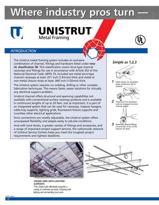
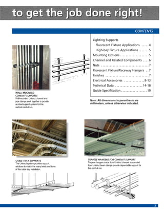
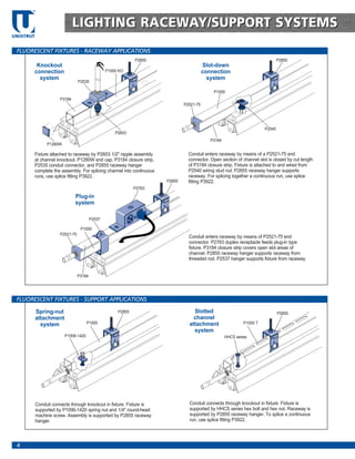
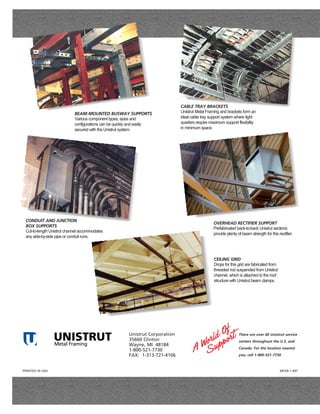
UNISTRUT
                            TM
                                                         ®


                                   Metal Framing


                                   ELECTRICAL CONSTRUCTION
                                   APPLICATION,
                                   INSTALLATION,
                                   SPECIFICATION
                                   GUIDE


Listed under new U/L Standard 5B
Where industry pros turn —
                                  UNISTRUT
                   TM
                                                                              ®


                                  Metal Framing

        INTRODUCTION

             The Unistrut metal framing system includes an exclusive
             combination of channel, fittings and hardware listed under new              Simple as 1,2,3
             UL classification 5B. This classification covers strut-type channel
             raceways and fittings for use in accordance with Article 352 of the
             National Electrical Code, NFPA 70. Included are metal strut-type
             channel raceways at least .071 inch (1.81mm) thick and metal or
             non-metal closure strips at least .040 inch (1.02mm) thick.                 1   Insert spring nut anywhere
                                                                                             along continuous slot of
             The Unistrut system requires no welding, drilling or other complex              channel.
             fabrication techniques. This means faster, easier solutions for virtually
             any electrical support problem.
             Unistrut channel offers structural and spanning capabilities not
             available with conventional surface raceway products and is available
             in continuous lengths of up to 20 feet. Just as important, it is part of
                                                                                         2   Press and turn clockwise
                                                                                             until nut engages inturned
             an integrated system that can be used for raceways, trapeze hangers,            channel edges.
             cable-tray supports, lighting grids, fluorescent-fixture supports and
             countless other electrical applications.
             Since connections are readily adjustable, the Unistrut system offers
             unsurpassed flexibility and adapts easily to job-site conditions.
             And with local stocks, a greater variety of fittings and accessories, and   3   Assemble desired fittings,
                                                                                             nut and bolt. A turn of the
             a range of important project support services, the nationwide network           wrench–it’s done.
             of Unistrut Service Centers helps you meet the toughest project
             requirements and tightest deadlines.


                             CEILING GRID WITH LIGHTING
                             SUPPORTS
                             This Unistrut grid effectively supports a
                             variety of overhead services, including both
                             lighting and air-handling duct work.
©1997 Unistrut
   2
to get the job done right!
                                                                                                        CONTENTS

                                                    Lighting Supports
                                                       Fluorscent Fixture Applications . . . . . 4
                                                       High-bay Fixture Applications . . . . . . . 5
                                                    Mounting Options . . . . . . . . . . . . . . . . . . . . 5
                                                    Channel and Related Components . . . . 6
                                                    Nuts . . . . . . . . . . . . . . . . . . . . . . . . . . . . . . . . . 7
                                                    Florescent Fixture/Raceway Hangers . . 7
                                                    Finishes . . . . . . . . . . . . . . . . . . . . . . . . . . . . . . 7
                                                    Electrical Accessories . . . . . . . . . . . . . . 8-13
                                                    Technical Data . . . . . . . . . . . . . . . . . . . 14-18
                                                    Guide Specification . . . . . . . . . . . . . . . . . . 19
WALL-MOUNTED
CONDUIT SUPPORTS
Wall-mounted Unistrut channel and
pipe clamps work together to provide             Note: All dimensions in parenthesis are
an ideal support system for this                 millimeters, unless otherwise indicated.
vertical conduit run.


CABLE TRAY SUPPORTS                            TRAPEZE HANGERS FOR CONDUIT SUPPORT
The Unistrut system provides support           Trapeze hangers made from Unistrut channel suspended
solutions to match the many twists and turns   from Unistrut beam clamps provide dependable support for
of this cable tray installation.               this conduit run.


                                                                                                                               3
TM


                               LIGHTING RACEWAY/SUPPORT SYSTEMS
UNISTRUT


 FLUORESCENT FIXTURES - RACEWAY APPLICATIONS
                                                               P2855                                                              P2855
            Knockout                                                                        Slot-down
           connection                             P1000 KO                                  connection
             system                                                                           system
                                  P2535

                                                                                                P1000
                       P3184
                                                                                 P2521-75


                                                                                                                          P2540
                                                      P2603
                                                                                               P3184
                 P1280W

           Fixture attached to raceway by P2603 1/2" nipple assembly               Conduit enters raceway by means of a P2521-75 end
           at channel knockout. P1280W end cap, P3184 closure strip,               connector. Open section of channel slot is closed by cut length
           P2535 conduit connector, and P2855 raceway hanger                       of P3184 closure strip. Fixture is attached to and wired from
           complete the assembly. For splicing channel into continuous             P2540 wiring stud nut. P2855 raceway hanger supports
           runs, use splice fitting P3922.                                         raceway. For splicing together a continuous run, use splice
                                                                         P2855     fitting P3922.
                                                               P2763

                               Plug-in
                               system

                                          P2537

                                   P1000
                       P2521-75
                                                                                   Conduit enters raceway by means of P2521-75 end
                                                                                   connector. P2763 duplex receptacle feeds plug-in type
                                                                                   fixture. P3184 closure strip covers open slot areas of
                                                                                   channel. P2855 raceway hanger supports raceway from
                                                                                   threaded rod. P2537 hanger supports fixture from raceway.


                                  P3184


 FLUORESCENT FIXTURES - SUPPORT APPLICATIONS

           Spring-nut                                  P2855                         Slotted                                      P2855
           attachment                                                                channel
             system                    P1000                                       attachment                   P1000 T
                                                                                     system
                          P1006-1420                                                                   HHCS series


           Conduit connects through knockout in fixture. Fixture is                Conduit connects through knockout in fixture. Fixture is
           supported by P1006-1420 spring nut and 1/4" round-head                  supported by HHCS series hex bolt and hex nut. Raceway is
           machine screw. Assembly is supported by P2855 raceway                   supported by P2855 raceway hanger. To splice a continuous
           hanger.                                                                 run, use splice fitting P3922.


 4
LIGHTING RACEWAY/SUPPORT SYSTEMS
                                                                                                    HIGH-BAY FIXTURE RACEWAY APPLICATIONS
                                        P3184                                                             P2536                          P1280W
              P2535                                  Fixture attached to and
                                                     wired from raceway by
                                                     1/2" nipple assembly of                                                      P3184
                                                                                           P2855
  P2855                                              desired length at channel                                                Fixtures are connected
                                           P1280W    knockout. P1280W end                                                     to and wired from
                                                     cap, P3184 closure strip,   P100 KO                                      raceway by conduit
                                                     P2535 conduit connector,                                                 hanger P2536 or P2535.
                                                     and P2855 raceway hanger                                                 Raceway is supported by
             P100 KO                                 complete assembly. For                                                   P2855 raceway hanger.
                                                     splicing channels into                                                   P1280W endcaps and
                                                     continuous raceway runs,                                                 P3184 closure strip
                                                     use splice fitting P3922.                                                complete the assembly.
             H.I.D.                                                                                                           Conduit connected to
           knockout                                                                                                           raceway through
           mounted                                                                                    High-bay                channel knockout.
            system                                                                                      dual
                                                P3184
                                                                                                      mounted                     P2602             P1280W
                                        P2763                                                          system
                                                                                                                              P3184
                                                                 P2521-75                                            P2761


                                                            H.I.D. plug-in         H.I.D. plug-in
                                                               system                  system
                                            P2855           (with swivel)          (rigid mount)
                                   P1000
                                                                                                                      P1000
                                P2855                                                                        P2535


                     P2855
  M2250
                                                                                                            Fixtures are supported by P2602 high
    Fixtures, supported by P2855 raceway hangers and                                                        bay lamp hangers. Cover plate on P2761
    M2250 swivel hangers, plug into receptacle mounted in                                                   outlet box provides access to receptacle
    P2763 receptacle unit. P2855 hangers also support                                                       box. Raceway is supported and wired by
    raceway. P2521-75 end connector joins conduit to                                                        top mounted P2535 conduit connectors.
    raceway. P1280W end caps (not shown) and P3184                                                          P1280W end caps and P3184 closure
    closure strip complete assembly.                                                         P2855
                                                                                                            strip complete assembly.


    Fixtures attached to and wired from P2535 or P2536 conduit hangers
    mounted to slot side of channel. Raceway can be wired by P2521-75
                                                                                                                   P2535
    end connector as shown, or conduit can enter through available
    knockout. Ballasts are connected at the knockouts by fixture adapter.
    In remote ballast installations, follow manufacturers instructions.                                                Uplighting with
    P2855 raceway hangers support both types of installations. P3184                                                    underhung or
    closure strip and P1280W end caps complete assembly. For                          P100 KO                          remote ballast
    continuous raceways, use splice fitting P3922.
                                                                                            P3184                             P2521-75


                                                                                                                                 MOUNTING OPTIONS
   A variety of clamps simplifies attachment to structural beams.


            P1379-S                                 P2867                    P3087                   P2675–P2676                P2785–P2786
          (use in pairs only)                                                                                                     (use in pairs only)

  Other mounting options include concrete inserts, expansion anchors and powder-actuated fasteners.


                                                                                                                                                             5
TM


                                    CHANNEL
UNISTRUT


 1-5/8” CHANNEL SELECTIONS

                               P1000                                              P1001                                        P3300                                         P3301


       12 gage (2.7)                                12 gage (2.7)                                       12 gage (2.7)                               12 gage (2.7)
       1 5/8" (41.3)x                               1 5/8" (41.3)x                                      1 5/8" (41.3)x                              1 5/8" (41.3)x
       1 5/8" (41.3)                                3 1/4" (82.6)                                       7/8" (22.2)                                 1 3/4" (44.5)

                                   P1100                                            P1101                                        P4000                                       P4001


            14 gage (1.9)                             14 gage (1.9)                                    16 gage (1.5)                                16 gage (1.5)
            1 5/8" (41.3)x                            1 5/8" (41.3)x                                   1 5/8" (41.3)x                               1 5/8" (41.3)x
            1 5/8" (41.3)                             3 1/4" (82.6)                                    13/16" (20.6)                                1 5/8" (41.3)
                                   P2000                                            P2001
                                                                                                                                   P5000                                       P5001


            14 gage (1.9)                           14 gage (1.9)                                       12 gage (2.7)                                    12 gage (2.7)
            1 5/8" (41.3)x                          1 5/8" (41.3)x                                      1 5/8" (41.3)x                                   1 5/8" (41.3)x
            1 5/8" (41.3)                           3 1/4" (82.6)                                       3 1/4" (82.6)                                    6 1/2" (165.1)
                                                                                                                                 P5500                                       P5501
                                   P3000                                            P3001


            14 gage (1.9)                           14 gage (1.9)                                       12 gage (2.7)                                   12 gage (2.7)
            1 5/8" (41.3)x                          1 5/8" (41.3)x                                      1 5/8" (41.3)x                                  1 5/8" (41.3)x
            1 3/8" (34.9)                           2 3/4" (69.9)                                       2 7/16" (61.9)                                  4 7/8" (123.8)


 PIERCED CHANNEL SELECTIONS

                          HS                                                  T                              KO                              H3                               DS


            9/16" holes on                       1 1/8" x 9/16" slots                 7/8" knockouts                     9/16" holes on            7/8" X 2 3/4" slots
            1 7/8" centers                       on 2" centers                        on 6" centers                      1 7/8" centers            on 3 1/2" centers


 CONCRETE INSERTS                                                                                                                                                        CLOSURE STRIPS


                                                              8"
                                                           (203.2)


                                                                              P3712P
                                                              Optional plastic filler to
                                                              prevent concrete seepage.
                         Wt.                          Wt.                           Wt.
                   Lgth Lbs/C                   Lgth Lbs/C                    Lgth Lbs/C
       P 3249       3"       85       P 3257    32"     527          P 3264   9'    1741
       P 3250       4"       100      P 3257A   36"     616          P 3265   10'   1947
       P 3251       6"       130      P 3258    40"     661          P 3266   12'   2334                  P3184 P                               P3184
       P 3252       8"       159      P 3259     4'     786          P 3267   14'   2717               Material: GE Noryl®                 Material: Steel
       P 3253       12"      227      P 3260     5'    1003          P 3268   16'   3116               Wt. 9.4 Lbs. / C Ft.                Wt. 47 Lbs. / C Ft.
       P 3254       16"      270                                                                       (14.0 kg/100 m)                     (69.9 kg/100 m)
                                      P 3261     6'    1173          P 3269   18'   3530
       P 3255       20"      357      P 3262     7'    1390          P 3270   20'   3882
       P 3256       24"      399      P 3263     8'    1560                                      Standard length -10 feet.


 6
NUTS/HANGERS
                                                                                                                                                                                     NUTS
                                                                                                                                                     Part         Thread     WT.
                            Part          Thread WT.                                Part          Thread       WT.                                  Number         Size     Lbs/C
                           Number          Size  Lbs/C                             Number          Size       Lbs/C
                                                                                                                                                    P3016-
                            P1006-                                                    P4006-                                                        0632        #6     32    2
                            1420        1/4"     20 7                                 1420        1/4"   20     7                                   0832        #8     32    2
                            P1007       5/16"    18 6                                 P4007      5/16"   18     6                                   1024       #10     24    4
                            P1008       3/8"     16 10                                P4008       3/8"   16     9                                   1420       1/4"    20    4
                            P1009       7/16"    14 9                                 P4009      7/16"   14     9
                                                                                                                                                    for P3300, P4000 & P5000
                            P1010       1/2"     13 12                                P4010       1/2"   13     8                                   channels
                                                                                                                                                      Part     Thread WT.
                                                                                                                                                    Number      Size    Lbs/C
                            P1012S 5/8" 11 21                                         P4012S 5/8" 11            11
                            P1023S 3/4" 10 21                                         P4023S 3/4" 10            11                                  P5506-
                            P1024S 7/8" 9 21                                                                                                        1420 1/4"          20    1
                                                                                      for P3300, P4000                                              P5507 5/16"        18     6
                           for P1000, P1100, P2000 &                                  channels
                                                                                                                                                    P5508 3/8"         16    10
                           P3000 channels
                                                                                                                                                    P5509 7/16"        14    10
                                                                                                                                                    P5510 1/2"         13    12
                                                                                                                                                    for P5500 channel

                                                                                                                                    FLUORESCENT FIXTURE HANGERS
                                                                                                                                                   1
     P2537                                                                                                                                          ⁄4" X 1" RHMS and
                                  1
                                      ⁄4" X 1" RHMS and                                                                                            Sq. Nut Included
     P5537                                                   Part  Use With                “A”           Weight/C
                                  Sq. Nut Included          Number Channel            In         mm      Lbs kg                                                       P2539
                                                                        P1000                                                                                         P3539
                                                                P2537   P1100    2 7/16          61.9    19      8.6                                                  P5539
                                                                                                                        A
    A                                                                   P2000
                                                                        P3000                                                                                       Design Load
                                                                                                                                                                   120 Lbs. (.5 kN)
                                                                P5537   P5500     3 1/4          82.6    22 10.0                                           5
                                                                                                                                                         1 ⁄8"
                                        1 5⁄8"                                                                                                           (41.3)
                                       (41.3)                           P1000
               9
                                                                P2539   P1100     1 3/4          44.5    17      7.7                          1
                                                                                                                                                  ⁄4" X 3⁄4"
                   ⁄32" (7.1) Dia. Hole
                                                                        P2000                                                                 Carriage Bolt
                                                                                                                                              and Sq. Nut Included
 Hanger provides more than 1/2" (12.7) space                    P3539   P3000     1 1/2          38.1    15      6.8
                                                                                                                       Hanger provides more than 1/8" (3.2) space
 between channel and fixtures.
                                   Design Load                  P5539   P5500    2 9/16          65.1    18      8.2   between channel and fixtures.
 Material: 18 gage (1.2)         120 Lbs. (.5 kN)                                                                      Material: 18 gage (1.2)


                                                                                                                                                        RACEWAY HANGERS

                                                                                                                                A                                     P2855
    P2755                         A                                Part         “A”               Weight/C
                                                                                                                                                                      P2856
    P2756                                                         Number   In         mm         Lbs    kg
                                                                                                                                                                      P2867
    P2757                                                         P2755 9/16          14.3       44      20
               4 1⁄4"                                             P2756 7/8           22.2       44      20            2 3⁄4"
              (108.0)                                                                                                  (69.9)
                                                                  P2757 13/32         10.3       44      20
                                                                  P2855 9/16          14.3       32      14.5
                                                                  P2856 7/8           22.2       32      14.5
                                                                                                                                               9                   Design Load
 Design Load                                                      P2857 13/32         10.3       32      14.5                                   ⁄32" (7.1)
120 Lbs. (.5 kN)                                                                                                                                                  120 Lbs. (.5 kN)
                                                  9
                                                   ⁄32" (7.1)                                                                                  Sq. Hole
                                                  Sq. Hole
Use with channels: P1001, P1101,                                                                                       Use with channels: P1000, P1100, P2000, P3000,
P2001, P5000 and P5500.                                                                                                P3300, P4000, P4001, P4100 and P4101.
Material: 14 gage (1.9)                                                                                                Material: 14 gage (1.9)


                                                                                                                                                                             FINISHES
Pregalvanized channel is coated with zinc by hot-dipped process prior to roll forming of press operations. The zinc weight coating is
0.45 oz./side per square foot of material conforming to ASTM specification A-653.
Electro-galvanized parts, screws and nuts are coated with zinc electrolytically to commercial standards. (Federal Specification No. QQ-Z-325A.)
Hot-dipped galvanized material is coated with zinc after being roll formed or after all manufacturing operations are completed. The zinc weight
is 2 oz. per square foot of surface conforming to ASTM specifications Nos. A-123 and/or A-153.
Nuts, bolts and pipe clamps are electro-galvanized.
(Alternate finishes may be specified, such as pregalvanized finish and hot-dipped galvanized finish for various parts of the metal framing
system. Refer to Unistrut General Engineering Catalog #12 and supplementary bulletins for the availability and appropriateness of the finish for
various parts.)


                                                                                                                                                                                       7
TM


                                     ELECTRICAL ACCESSORIES
UNISTRUT


 CONDUIT HANGER CONNECTION FOR 1/2” CONDUIT                                                         CONDUIT HANGER CONNECTION FOR 3/4” CONDUIT
                                                                                                                                          1
                                                                           1
                                                                                                                                           ⁄4" X 5⁄8" Flat Head
                                                                           ⁄4" X 5⁄8" Flat Head      P2536                                Machine Screws and
                P2535          7                                           Machine Screws and
                                ⁄8" (22.2) Dia.                                                                                           P3016-1420 Nuts Included
                                                                           P3016-1420 Nuts                     1 3⁄32" (27.8) Dia.
         Design Load                                                       Included
       400 Lbs (1.3 kN)                                                                              Design Load
                                                                                                   200 Lbs (1.3 kN)


                                                                                                  1 5⁄8"
                                                          4"                                      (41.3)                                      5 1⁄8"
                                                        (101.6)                                                                               (130.2)
      Material: 12 gage (2.7)                             Wt./C 28 lbs. (12.7 kg)                 Material: 16 gage (1.5)                          Wt./C 36 lbs. (16.3 kg)


 OUTLET BOX CONNECTION                                                                                                      END CONNECTORS FOR 1/2” CONDUIT
                                                1
                                                    ⁄4" X 5⁄8" Flat Head
                                                Machine Screws and
                   P2522                 1 15⁄16" P3016-1420 Nuts Included
                                                                                                     P3521-50
                                 1 3⁄16" (49.2)
                         1 3⁄16" (30.2)                                                                                                                              7
                                                                                                                                                                         ⁄8" (22.2) Dia.
                1 15⁄16" (30.2)                                                                                             P3000
                 (49.2)


                                                                                                       1                                                2 1⁄4"
                                      6 1⁄4"                                                            ⁄4" X 5⁄8" Flat Head Machine                    (57.2)
                                     (158.8)           3 Knockouts                                     Screw and P3016-1420 Nut
                                                       7
                                                         ⁄8" (22.2) Dia.                               Included
     Material: 12 gage (2.7)                                  Wt./C 35 lbs (15.9 kg)              Material: 12 gage (2.7)                       Wt./C 27 lbs. (16.3 kg)


 END CONNECTORS FOR 1/2” & 3/4” CONDUIT                                                                              END CONNECTORS FOR 1/2” & 3/4” CONDUIT
                                                                                                                                           P5500
                P2521-50                                                           A                    P5521-50                                                               A
                P2521-75                                                                                P5521-75
       1
        ⁄4" X 5⁄8" Flat Head                                                                                     1
       Machine Screw and                                                                                          ⁄4" X 5⁄8" Flat Head
       P3016-1420 Nut                                                                                            Machine Screw and
       Included                                                                                                  P3016-1420 Nut
                                                                    2 1⁄16"                                      Included
                                                                    (52.4)                                                                                        1 3⁄8"
                                                                                                                                                                  (34.9)
       Part    Conduit Size A             Weight/C                                                 Part   Conduit Size A             Weight/C
      Number        In                    Lbs kg              For Unistrut channels               Number       In                    Lbs kg
                                                              P1000, P1100 & P2000.
      P2521-50     1/2                    27 12.2             Material: 12 gage (2.7)             P5521-50    1/2                    27 12.2
      P2521-75     3/4                    26 11.8                                                 P5521-75    3/4                    26 11.8      Material: 12 gage (2.7)


 END CONNECTORS FOR 1/2” & 3/4” CONDUIT                                                                                        END CONNECTORS FOR 1” CONDUIT
                                                                                                                                          Tapped for 1"
                                       P5500
                  P5021-50                                                     A                                                                         Conduit Thread
                                                                                                                     P2521-100
                  P5021-75
       1                                                                                                                             P1000
           ⁄4" X 5⁄8" Flat Head
       Machine Screw and
                                                                                                           1
       P3016-1420 Nut                                                                                       ⁄4" X 5⁄8" Flat Head
       Included                                                                                            Machine Screw and
                                                                                                           P3016-1420 Nut                                                 2 1⁄16"
                                                                  1 3⁄8"
                                                                  (34.9)                                   Included                                                       (52.4)
            Part       Conduit Size A          Weight/C
           Number           In                 Lbs kg
           P5021-50           1/2              31      14.1                                                Not UL-listed or CSA approved
           P5021-75           3/4              30      13.6     Material: 12 gage (2.7)                    Material: 12 gage (2.7)                               Wt./C 24 lbs. (10.9 kg)


 8
ELECTRICAL ACCESSORIES
END CONNECTOR FOR 1” CONDUIT                                                                                                                  END CONNECTOR FOR 1” CONDUIT
                                                     Tapped for 1"                                                                                 Tapped for 1"
                                                     Conduit Thread                                                                                Conduit Thread
           P5021-100                                                                                         P5521-100
                                         P5000                                                                                      P5500
 Material: 12 gage (2.7)                                                                                Material: 12 gage (2.7)
 Wt/C 28 Lbs (12.7 kg)                                                                                  Wt/C 24 Lbs (10.9 kg)

                                                                                                      1
                                                                                                       ⁄4" X 5⁄8" Flat Head
   1           5
    ⁄4" X ⁄8" Flat Head                                                                               Machine Screw and
   Machine Screw and                                                                                  P3016-1420 Nut
                                                                                                                                                                   1 5⁄8"
   P3016-1420 Nut                                                                                     Included                                                     (41.3)
                                                                        1 5⁄8"
   Included                                                             (41.3)
 Not UL-listed or CSA approved                                                                          Not UL-listed or CSA approved


WIREWAY END CAPS                                                                                     HIGHBAY LAMP HANGER                                       FIXTURE WIRING NIPPLE
                                                                                                               1 5/8"                                                            1.100"
P1180 W                                                                                             P2602      (41.3)                                          P2603             (27.9)
through                                           PART           USE             WEIGHT/C
P5580 W                                          NUMBER          WITH            Lbs   kg
                                                 P1180 W         P1100           12     5.4
                                                                                                                 3 1/2"
                                                 P1280 W         P1000           11     5.0                      (88.9)
                                                 P2280 W         P2000           11     5.0                                                 6 23/32"                2 1/8"
                                                                                                                                            (170.6)                 (54.0)
                                                 P3280 W         P3000            8     3.6
                                                                                                                      5/16" (7.9)
                                                 P4280 W         P4000            5     2.3                            Dia. Hole
                                                 P5280 W         P5000           22    10.0
                                                 P5580 W         P5500           18     8.2
                                                                                                                                                                   Hole
                                                                                                                                                                .600" Dia.
                                                                                                                           1 7/8"                                 (15.2)         .800"
                                                                                                                           (47.6)                                                (20.3)
Material: .075" (1.9)
                                                                                               Material: 12 gage (2.7)          Wt./C 153.8 lbs (69.8 kg)     Wt./C 14 lbs (06.3 kg)


SPACER CLEVIS                                                                                                                                                           WIRING STUD NUT
                                                            7
                         P2541                               ⁄8" Dia.
                                                            (22.2)                                                            P2540
            UNISTRUT Channel
                                                                                                                              P2540A
    1
     ⁄8"                                                                                                                                                                     A
   (3.2)                                 P2541


                                  P2540 Wiring
                                                                                            2"
                                  Stud Nut                                    2"          (50.8)
                   Flourescent Fixture
                                                                            (50.8)                                            Material: Sintered metal.
                                                           1 21⁄32"                 4"
                                                           (42.1)                 (101.6)                                    PART        CONDUIT SIZE A        WEIGHT/C
                                                                                                                            NUMBER         In     mm          Lbs    kg
           Material: 12 gage (2.7)                                                                                            P2540       1-1/8        28.6   10       4.5
           Wt./C 24 lbs (10.9 kg)
                                                                                                                              P2540 A      5/8         15.9   8        3.6


FIXTURE STUD NUT                                                                                                                                  POLYPROPYLENE WIRE RETAINER

                                                                                                 P2552
       P3116-125                                                                     1 1⁄2"                          1 1⁄2"
                   1
                     ⁄4" x 20 Thd.                                                   (38.1)                          (38.1)
                                                 1 3⁄16"
                                                 (30.2)


                                                                                 Retainer can be easily pushed
                                                                                 into channel to support wires
                                                                                 until closure strip is installed.
    Wt/C 11 lbs (5.0 kg)
                                                                                                                                                               Wt/C .30 lbs (.1 kg)


                                                                                                                                                                                          9
TM


                                    ELECTRICAL ACCESSORIES
UNISTRUT


 SPLICE FITTINGS
                                                                                                                   Assembly Use                    “A”      Clevis  Back   Plate                       Weight/C
                                                                                                                    Number With                            Number Clevis    Nut
      P3922 -                                                           P2869 14 gage (1.9)                                Channel            In     mm            Number Number                       Lbs    kg
      P3926                                                                                                                   P1000
                                                             A                                                          P3922 P1100 1 5/8 41.3 P2377                       P2517       P2869         100     45.4
                                                                                                                              P2000
                                                                                               Threaded                 P3923 P3000 1 3/8 34.9 P3377                       P2517       P2869           97    44.0
                                                                                               Plate Nut
                                                                                                                        P3924 P4000 13/16 20.6 P5377                       P2517       P2869           80    36.3
                                       3                      5                                                         P3925 P5500 1 5/8 41.3 P2377                       P5517       P2869         103     46.7
                                     6 ⁄4"              1
                                                         ⁄4" X ⁄8" Flat Head Machine Screws
                                    (171.5)             and 4 Hole Splice Plate Nut Included                            P3926 P5000 1 5/8 41.3 P2377                       P5017       P2869         106     48.1

                                                                                                                   Material: 16 gage (1.6)


 CONDUIT SWING FITTING
                                                                                                                         2"
                                                                                                                       (50.8)                                       4 13⁄16"
                 P2534-50                                                                                                                                           (122.2)
                 P2534-75                                                                                                                                    2"                 2"
                                                                                                                                                           (50.8)             (50.8)
      • Conduit hanger fittings allow a free
        swivel of 15˚ in one direction.                                                                                             2 Holes
                                                                                               P2534-50 For 1⁄2" Rigid Conduit
      • Fitting may be mounted to the slot side                                                                                     9
                                                                                               P2534-75 For 3⁄4" Rigid Conduit       ⁄32" (7.1) 3⁄16"
        of the Unistrut channel or to the back.                                                                                                  (4.8)
      Wt./C 96 Lbs (43.5 kg)
                                                                                                1
                                                                                                 ⁄4" X 3⁄4" Slotted Hex Head                                                                   Ground Wire
                                                                                                Screws and Nuts Included
                                                                                                                                                   Bushing
                                                                                      15°                                                          Not Included
                 Design Load                                           15°           (.08π)
               300 Lbs. (1.3 kN)                                      (.08π)


 IN-CHANNEL JOINERS
                 P2900                                            P2901                                                         P2902                                               P2903
            Wt./C 20 lbs (9.1 kg)                           Wt./C 35 lbs (15.9 kg)                                       Wt./C 27 lbs (12.2 kg)                              Wt./C 45 lbs (20.4 kg)

                      P1000                                                                                   P1000                                                                                          P1000


                                                                                              P1000


           All Material: Cast Aluminum

 BRACKETS
                                                                                                                                                                                   2" (50.8)
                                                                                                            2"
       P2513A-                             2"
                                       (50.8)                     P2513 -                                 (50.8)                                  P2542 -         13
                                                                                                                                                                    ⁄16"
       P2516A                                                     P2516                                            1
                                                                                                                       ⁄4"
                                                                                                                                                  P2546           (20.6)
                                                1                                                                                                                                                A
                                                 ⁄4"                                                               (6.4)
                                                (6.4)
                                                                                 3
                    3 3⁄4"                                                     3 ⁄4"
                    (95.3)                                                     (95.3)
                                                                                                                                                               6 1⁄4"
                                                                                                                                                               (158.8)


                                                                                                                                                                                               P1001
                                                                                                                                                                               3
                                                                                                                                                                                ⁄8"
                                                                                                             A                                                                 (9.5)
                                           A                                                                                                        Part         Std.
        Part               Std.                                    Part                 Std.                                                       Number      Lengths
       Number            Lengths                                  Number              Lengths
                                                                                                                                                   P2542               12"
       P2513A                 6"                                  P2513                        6"                                                  P2543               18"
       P2514A                 12"                                 P2514                       12"                                                  P2544               24"
       P2515A                 18"                                 P2515                       18"                                                  P2545               30"
       P2516A                 24"                                 P2516                       24"                                                  P2546               36"

 10
ELECTRICAL ACCESSORIES
                                                                                                                             DUPLEX GROUNDED RECEPTACLE
                                                                        P2553
                      P2557                                             Wire Connectors                              Oval Head
                                                                                                                     #6-32 X 1"
      • 125 V, 15 amp receptacle, NEMA
        configuration S-15R, cover plate.
      • #6 screws, nuts and wire connectors
        included.                                                                       6"
      • Leads are 14 gage 105˚C plastic                                               (152.4)
        covered.
      • Ground wire is green 16 gage.                                                                 P3016-0632

      Finish: White powder coat.
      Wt./C 38 Lbs (17.2)

                                                                                                                         P3184 Closure


                                                                                                                                                  RECEPTACLE BOX

          P2761               7
                                  ⁄8" Knockout
                                                        1⁄4"   x 5⁄8"
          P2762                                                                                                      Part                          Weight/
                                                                                                                    Number         Outlet        Lbs    kg
                                                                                                                     P2761         Single         88       39.9
                                                                                                                     P2762         Duplex         88       39.8


                                                                Includes Nuts
                                                                and Screws


                                                        P3016-1420


                                                                                                                                                  RECEPTACLE UNIT
 P2763                                                                                                                                                NEMA
 P2764            7
                   ⁄8" Knockout         1⁄4"   x 5⁄8"                                                  Part                         Weight/         Receptacle
 P2765                                                                                                Number          Outlet       Lbs    kg       Configuration
                                                                                                       P2763           125V        108      49          5-15R
                                                                                                       P2764           250V        108      49          6-15R
                                                                                                       P2765           277V        108      49          7-15R
                                          Includes Nuts
                                          and Screws


                                         P3016-1420


                                                                                                                                                   JUNCTION BOXES
        P2810                                                                      P2812                                                         P2814
 Wt./C 135 lbs (61.2 kg)                                                    Wt./C 155 lbs (70.3 kg)                                      Wt./C 195 lbs (88.5 kg)


                                           P2811                                                               P2813
                                   Wt./C 155 lbs (70.3 kg)
                                                                                                        Wt./C 175 lbs (79.4 kg)


ALL JUNCTION BOXES ILLUSTRATED ON THIS PAGE:
 • UL Listed • Junction boxes are for P1000, P1100 or P2000 channels • All channels entries in box are 1 1/8" (28.6) diameter finished holes
   with no bushing needed. All knockouts are 7/8" (22.2) diameter. • 1/4" x 5/8" flat head machine screws and P3016-1420 nuts included.

                                                                                                                                                                   11
TM


                                ELECTRICAL ACCESSORIES
UNISTRUT


 PORCELAIN CABLE CLAMPS                                                                                                         4” (101.6) BUS BAR MAPLE CLAMPS

      P1787A                                                                                              P2647 A                                   1 5⁄8"
                                                                                                                                                    (41.3)
      through                                                                                             through
      P1795 B                                                                                             P2647 F                                                        A
                           Hole Size                                                                                                            B


                                                                                              • 1/2" studs, square nuts and
                                                                                                washers are included.                   4"
                                                                                                                                      (101.6)
                                                                                              • Channel nuts must be ordered
                                                                                                separately.
                                                                                                                                                                                          7 3⁄8"
                                                                                              • Bus bar maple clamps also                                                                (187.3)
                                                                                                available in 1/4" (6.4) x 2" (50.8)
                                                       A                                        and 1/4" (6.4) x 6" (152.4)              1⁄4" (5.4) Maple

                                                                                                                                         Separator
            Use with steel clamp and Everdur hardware. Order clamp separately.                 Material: Paraffin impregnated
            Material: Dry process porcelain white glaze.                                       maple hardwood.

      Assembly         Order Steel         Hole Size             “A”          Weight/C
       Number            Clamp                                                               Assembly
                        Number         In       mm          In         mm     Lbs    kg                         “A”                   “B”           No. Bus
                                                                                              Number                                                 Sepa- No. Bars              Weight/C
                                                                                                           In         mm        In          mm       rators Per Leg             Lbs     kg
           P1787 A                   3/8          9.5                         54     24.5
           P1787 B      P1113 E      1/2        12.7       1 7/8       47.6   53     24.0    P2647 A      8 1/2    215.9         9/32       7.1          0           1          421    191.0
           P1787 C                   5/8        15.9                          51     23.1    P2647 B      9 1/2    241.3        13/16 20.6               2           2          465    210.9
                                                                                             P2647 C 10 1/2        266.7     1 5/16 33.3                 4           3          509    230.9
           P1788                     3/4        19.1                          94     42.6
                                                                                             P2647 D 11 1/2        292.1 1 13/16 46.0                    6           4          553    250.8
           P1788 A                   7/8        22.2                          89     40.4
                        P1115 E                            2 3/8       60.3                  P2647 E     12 1/2    317.5        2 3/8 60.3               8           5          597    270.8
           P1788 B                     1        25.4                          84     38.1
                                                                                             P2647 F     13 1/2    342.9        2 7/8 73.0              10           6          631    286.2
           P1788 C                   1 1/8      28.6                          81     36.7

           P1789                     1 1/4      31.8                          122    55.3
           P1789 A                   1 3/8      34.9                          119    54.0
                        P1117 E                            2 7/8       73.0                                                                             MAPLE CABLE CLAMPS
           P1789 B                   1 1/2      38.1                          114    51.7
           P1789 C                   1 5/8      41.3                          111    50.3

           P1790                     1 3/4      44.5                          238   108.0
                                                                                                 P1690
           P1790 A                   1 7/8      47.6                          232   105.2
                        P1119 E                             4      101.6                         through
           P1790 B                     2        50.8                          221   100.2        P1697
           P1790 C                   2 1/8      54.0                          217    98.4
                                                                                                                                                Hole Size

           P1791                     2 1/4      57.2                          274   124.3       • Use with steel clamp and
                        P1120 E                            4 1/2   114.3                          Everdur hardware. Order clamp
           P1791 A                   2 3/8      60.3                          267   121.1         separately.
           P1791 B                   2 1/2      63.5                          259   117.5
                                                                                                • Specify hole size when
           P1791 C      P1120 E      2 5/8      66.7       4 1/2   114.3      252   114.3         ordering.

           P1792                     2 3/4      69.9                          347   157.4
                                                                                                 Material: Paraffin impregnated                                          A
           P1792 A                   2 7/8      73.0                          336   152.4        maple hardwood.
                        P1121 E                            5 1/8   130.2
           P1792 B                     3        76.2                          325   147.4
           P1792 C                   3 1/8      79.4                          314   142.4
                                                                                            Assembly Order Steel
                                                                                            Number     Clamp                    Hole Size                          “A”           Weight/C
           P1793                     3 1/4      82.6                          495   224.5
                                                                                                      Number               In                   mm            In         mm     Lbs    kg
           P1793                     3 3/8      85.7                          480   217.7
                        P1123 E                            6 1/8   155.6
           P1793 A                   3 1/2      88.9                          465   210.9   P2647 A P1113 E           0    – 5/8            0     – 15.9     1 1/2       38.1    24    10.9

           P1793 C                   3 5/8      92.1                          450   204.1   P1691       P1115 E       1/2 –       1     12.7 – 25.4          2 1/8       54.0    42    19.1

           P1794                     3 3/4      95.3                          712   323.0   P1692       P1117 E       3/4 – 1 1/2 19.1 – 38.1                2 5/8       66.7    54    24.5
           P1794 A                   3 7/8      98.4                          696   315.7
                        P1124 E                            7 1/4   184.2                    P1693       P1118 E 1 1/4 – 1 3/4 31.8 – 44.5                     3          76.2    65    29.5
           P1794 B                     4       101.6                          683   309.8
           P1794 C                   4 1/8     104.8                          670   303.9   P1694       P1119 E 1 1/2 – 2 1/4 38.1 – 57.2                    3 5/8       92.1    84    38.1

           P1795                     4 1/4     108.0                          645   292.6   P1695       P1120 E       2    – 2 1/2 50.8 – 63.5               4 1/8 104.8         107   48.5
           P1795 A      P1124 E      4 3/8     111.1       7 1/4   184.2      632   286.7   P1696       P1121 E 2 1/4 –           3     57.2 – 76.2          4 5/8 117.5         123   55.8
           P1795 B                   4 1/2     114.3                          617   279.9
                                                                                            P1697       P1123 E       3    –      4     76.2 – 101.6 5 3/4 146.1                 163   73.9


 12
ELECTRICAL ACCESSORIES
                                                                                                                                                                                                    CABLE SADDLES
 P1753 FG                            2"
 P1754 FG                                                A                                       Assembly
                                   (50.8)                                                                                           “A”                    Maximum
                                                                                                  Number                                                 Cable Diameter                       Weight/C
 P1753 PO                                                                                                                    In           mm              In       mm                       Lbs        kg
 P1754 PO
                                                                                                 P1753 FG               2 13/16           71.4           3                  76.2            12             5.4
                                                                                                 P1754 FG               3 3/4             95.3           4 1/2            114.3             17             7.7
                                                                                                 P1753 PO               3                 76.2           3                  76.2            75         34.0
  Material: FG - Fiberglass Reinforced Polyester.                                                P1754 PO               4                101.6           4 1/2            114.3             95         43.1
            PO - Dry Process White Glazed Porcelain.


                                                                                                                                                                                      MAPLE CABLE SADDLES
 P2649 A                                                                         Assembly
 through                      1 5⁄8"                                              Number                  Hole Size                                     “A”                           “B”             Weight/C
                              (41.3)                A                                              In                       mm                   In              mm              In         mm       Lbs     kg
 P2649 H
                 Hole Size                                                       P2649 A     0      –         1     0           – 25.4           3               76.2       1 3/4           44.5      31          14.1
                                                                                 P2649 B     1      – 1 1/2         25.4 – 38.1              3 1/2               88.9            2          50.8      38          17.2
                                                                      B
                                                                                 P2649 C    11/2 –            2     38.1 – 50.8                  4           101.6          2 1/4           57.2      47          21.3
                                                                                 P2649 D     2      – 2 1/2         50.8 – 63.5              4 1/2           114.3          2 1/2           63.5      57          25.9
                                                                                 P2649 E    2 1/2 –           3     63.5 – 76.2                  5           127.0          2 3/4           69.9      68          30.8

• 3/8" flat head machine screw included.                                         P2649 F     3      – 3 1/2         76.2 – 88.9              5 1/2           139.7               3          76.2      80          36.3
• Specify hole size when ordering.                                               P2649 G    3 1/2 –           4     88.9 – 101.6                 6           152.4          3 1/4           82.6      94          42.6
• Order channel nuts as required.
  Material: Paraffin impregnated maple hardwood.                                 P2649 H         over 4                 over 101.6


                                                                                                                                                                                       MAPLE CABLE CLAMPS
                                                                                              Assembly                                                                       “A” and “B”
 P2645 A                                 1 5⁄8"
                                                                  A                            Number                                 Hole Size                              Dimensions                Weight/C
 through                                (41.3)                                                                              In                          mm                    In     mm              Lbs      kg
 P2645 H                                                                                      P2645 A              0        –        1           0       –       25.4       3 1/2           88.9      84          38.1
                                                                                              P2645 B              1        – 1 1/2              25.4 –          38.1            4      101.6        102          46.3
• 3/8" studs, square nuts                                                                     P2645 C             1 1/2 –            2           38.1 –          50.8       4 1/2       114.3        121          54.9
  and washers included.        Hole Size                                            B
                                                                                              P2645 D              2        – 2 1/2              50.8 –          63.5       5 1/2       139.7        165          74.8
• Specify hole size
  when ordering.                                                                              P2645 E             2 1/2 –            3           63.5 –          76.2            6      152.4        189          85.7
• Order channel                                                                               P2645 F              3        – 3 1/2              76.2 –          88.9       6 1/2       165.1        215          97.5
  nuts as required.
                                                                                              P2645 G             3 1/2 –            4           88.9 – 101.6                    7      177.8        243         110.2
 Material: Paraffin
 impregnated maple hardwood.                                                                  P2645 H                   over 4                       over 101.6


                                                                                                                                                                                                   SWIVEL HANGERS
M2037             A                                  M2137                         A
                                                                                                                                          M2250
M2050                                                M2150
                                                                                                                                    Wt./C 18 lbs (8.2 kg)               1 3⁄4"                                    3
                                                                                                                                                                                                                   ⁄8"
                                                                                                                                                                        (44.5)
                                                                                                          3                                                                                                (9.5) Dia.
                                            3                                                             ⁄8"
                                            ⁄8"                              B
          B
                                   (9.5) Dia.                                                    (9.5) Dia.                                                        1"
                                                                                                                                                              (24.5)

                                                                      1"
                                                                  (24.5)
                               A                                                                                                                                  3
                                                                                                                                                                      ⁄8" (9.5) Dia.                  1
                                                                                                                                                                                                          ⁄2" - 13 Thd.
      Part                                  “B”               Weight/C                        A                                 3
                                                                                                                            1 ⁄4"
     Number             “A”            In         mm         Lbs    kg
                                                                                                                         (44.5)
      M2037           3/8" - 16     2 31/32"      67.5       23       10.4
                                                                                                                                                             1
      M2050           1/2" - 13     2 3/4"        69.9       32       14.5                                                                                    ⁄2" - 13 Thd.
      M2137           3/8" - 16     2 29/32"      67.5       27       12.2
                                                                                                                                                                                                   M2350
      M2150           1/2" - 13     2 3/4"        69.9       45       20.4                                                                                                                   Wt./C 20 lbs (9.1 kg)

                                                                                                                                                                                                                          13
TM


                             TECHNICAL DATA
UNISTRUT


 BEAM AND COLUMN LOADS
                                                             Beam Data                                           Column Data
                                        Maximum          Deflection At     Uniform Load        Maximum Column         Maximum Design
                  Span     Channel      Allowable        Uniform Load       At Deflection         Load Applied        Load Applied At
                                     Uniform Load                            Span/240            At C.G. (K= .80)       Column Face
             In     mm                Lbs        kg       In      mm      Lbs           kg      Lbs            kg      Lbs       kg
             24     610    P1000     1690        767      0.06     1      1690         767     10200          4627     3490     1583
                           P1001     3130*      1420*     0.02     1      3130*       1420*    23560        10687      6360     2885
                           P1100     1390        630      0.06     2      1390         630      7670          3479     2800     1270
                           P1101     1850*       839*     0.02     1      1850*        839*    17690          8024     4990     2263
                           P2000     1170        531      0.06     1      1170         531      6200          2812     2350     1066
                           P2001     1370*        621*    0.01     0      1370*        621*    14450          6554     4120     1869
                           P3000     1290        585      0.07     2      1290         585      9330          4232     3100     1406
                           P3001     2660*      1207*     0.03     1      2660*       1207*    21310          9666     5660     2567
                           P3300       600       272      0.10     3       600         272      7380          3348     2140      971
                           P3301     1660*       753*     0.06     1      1660*        753*    16390          7434     4110     1864
                           P4000       400       181      0.11     3       380         172      4190          1901     1440      653
                           P4001      690*       313*     0.04     1       690*        313*     9800          4445     2650     1202
                           P4100       440       200      0.11     3       410         186      5340          2422     1630      739
                           P4101      910*       413*     0.05     1       910*        413*    11720          5316     3030     1374
                           P5000     5260†      2386†     0.03     1      5260†       2386†    15850          7189     5700     2585
                           P5001     6170*†     2799*†    0.01     0      6170*†      2799*†   30170        13685      7730     3506
                           P5500     3280       1488      0.04     1      3280        1488     13080          5933     4640     2105
                           P5501     4680*      2123*     0.01     0      4680*       2123*    30870        14002      8540     3874
             36     914    P1000     1130        513      0.13     3      1130         513      8400          3810     3150     1429
                           P1001     3130*      1420*     0.07     2      3130*       1420*    22610        10256      6190     2808
                           P1100       930       422      0.13     3       930         422      6170          2799     2500     1134
                           P1101     1850*       839*     0.05     1      1850*        839*    17000          7711     4860     2204
                           P2000       780       354      0.13     3       780         354      4650          2109     2030      921
                           P2001     1370*        621*    0.05     1      1370*        621*    13900          6305     4020     1823
                           P3000       860       390      0.15     4       860         390      7950          3606     2800     1270
                           P3001     2410       1093      0.08     2      2410        1093     20410          9258     5480     2486
                           P3300       400       181      0.22     6       270         122      5920          2685     1790      812
                           P3301     1130        513      0.13     3      1130         513     15080          6840     3820     1733
                           P4000       270       122      0.24     6       170           77     2900          1315     1140      517
                           P4001      690*        313*    0.14     4       690*        313*     8980          4073     2440     1107
                           P4100       300       136      0.25     6       180           82     4160          1887     1340      608
                           P4101       790       358      0.14     4       790         358     10680          4844     2790     1266
                           P5000     3510       1592      0.07     2      3510        1592     11580          5253     5000     2268
                           P5001     6170*†     2799*†    0.02     1      6170*†      2799*†   29330        13304      7650     3470
                           P5500     2190        993      0.09     2      2190         993     10190          4622     4160     1887
                           P5501     4680*      2123*     0.03     1      4680*       2123*    29720        13481      8400     3810
             48     1219   P1000       850       386      0.22     6       760         345      6540          2966     2750     1247
                           P1001     2400       1089      0.13     3      2400        1089     21270          9648     5970     2708
                           P1100       700       318      0.23     6       610         277      4460          2023     2110      957
                           P1101     1850*       839*     0.12     3      1850*        839*    16030          7271     4690     2127
                           P2000       590       268      0.23     6       510         231      2790          1266     1550      703
                           P2001     1370*       621*     0.11     3      1370*        621*    13120          5951     3880     1760
                           P3000       650       295      0.26     7       500         227      6600          2994     2470     1120
                           P3001     1810        821      0.15     4      1810         821     19160          8691     5240     2377
                           P3300       300       136      0.40    10       150           68     3830          1737     1400      635
                           P3301       850       386      0.23     6       730         331     13260          6015     3470     1574
                           P4000       200         91     0.42    11        90           41     1650            748     830      376
                           P4001       520       236      0.25     6       410         186      7830          3552     2200      998
                           P4100       220       100      0.43    11       100           45     2620          1188     1020      463
                           P4101       590       268      0.25     6       470         213      9210          4178     2500     1134
                           P5000     2630       1193      0.12     3      2630        1193      7230          3279     3950     1792
                           P5001     5650†      2563†     0.05     1      5650†       2563†    28170        12778      7540     3420
                           P5500     1640        744      0.15     4      1640         744      7040          3193     3480     1579
                           P5501     4680*      2123*     0.08     2      4680*       2123*    28120        12755      8190     3715
             60     1524   P1000       680       308      0.35     9       490         222      4980          2259     2360     1070
                           P1001     1920        871      0.20     5      1920         871     19560          8872     5690     2581
                           P1100       560       254      0.36     9       390         177      3250          1474     1750      794
                           P1101     1530        694      0.20     5      1530         694     14780          6704     4470     2028
                           P2000       470       213      0.36     9       330         150      1780            807    1170      531
                           P2001     1270        576      0.20     5      1270         576     12110          5493     3700     1678
                           P3000       520       236      0.41    10       320         145      5310          2409     2150      975
                           P3001     1450        658      0.23     6      1450         658     17550          7961     4940     2241
                           P3300       240       109      0.62    16       100           45     2450          1111     1080      490
                           P3301       680       308      0.37     9       460         209     10900          4944     3070     1393
                           P4000       160         73     0.66    17        60           27     1060            481     620      281
                           P4001       420       191      0.40    10       260         118      6350          2880     1920      871
                           P4100       180         82     0.69    17        70           32     1680            762     780      354
                           P4101       470       213      0.39    10       300         136      7330          3325     2180      989
            *Load limited by spot weld shear      †Bearing load limited by capacity                                   (cont’d on next page)

            See notes on page 16
 14
TECHNICAL DATA
                                                                                   BEAM AND COLUMN LOADS (CONTINUED)
                                                    Beam Data                                          Column Data
                              Maximum        Deflection At       Uniform Load        Maximum Column           Maximum Design
        Span     Channel      Allowable      Uniform Load        At Deflection         Load Applied            Load Applied At
                            Uniform Loan                           Span/240           At C.G. (K= .80)           Column Face
   In     mm               Lbs        kg       In       mm      Lbs          kg       Lbs          kg           Lbs        kg
                 P5000     2110       957    0.18        5      2110         957      5020         2277         3170      1438
                 P5001     4520†     2050†   0.08        2      4520†      2050†     26670       12097          7390      3352
                 P5500     1310       594    0.24        6      1310         594      5130         2327         2910      1320
                 P5501     3870      1755    0.13        3      3870       1755      26060       11821          7920      3592
                 P1000      560       254    0.50       13       340         154      4030         1828         2060       934
  72      1829   P1001     1600       726    0.28        7      1600         726     17460         7920         5360      2431
                 P1100      460       209    0.51       13       270         122      2560         1161         1500       680
                 P1101     1270       576    0.28        7      1270         576     13260         6015         4220      1914
                 P2000      390       177    0.52       13       230         104      1240          562          900       408
                 P2001     1060       481    0.28        7      1060         481     10890         4940         3490      1583
                 P3000      430       195    0.59       15       220         100      4330         1964         1860       844
                 P3001     1200       544    0.33        8      1080         490     15570         7062         4610      2091
                 P3300      200         91   0.89       23        70          32      1700          771          860       390
                 P3301      560       254    0.52       13       320         145      8080         3665         2640      1197
                 P4000      130         59   0.93       24        40          18       730          331          480       218
                 P4001      350       159    0.57       15       180          82      4620         2096         1630       739
                 P4100      150         68   0.99       25        50          23      1160          526          610       277
                 P4101      390       177    0.56       14       210          95      5240         2377         1840       835
                 P5000     1750       794    0.26        7      1750         794      3810         1728         2640      1197
                 P5001     3770      1710    0.11        3      3770       1710      24830       11263          7200      3266
                 P5500     1090       494    0.34        9       950         431      4060         1842         2510      1139
                 P5501     3220      1461    0.19        5      3220       1461      23540       10678          7590      3443
                 P1000      480       218    0.68       17       250         113      3390         1538         1820       826
  84      2134   P1001     1370       621    0.39       10      1240         562     14980         6795         4970      2254
                 P1100      400       181    0.70       18       200          91      2120          962         1310       594
                 P1101     1090       494    0.38       10       990         449     11460         5198         3920      1778
                 P2000      340       154    0.72       18       170          77       910          413          710       322
                 P2001      910       413    0.39       10       820         372      9440         4282         3250      1474
                 P3000      370       168    0.80       20       160          73      3620         1642         1630       739
                 P3001     1030       467    0.45       12       790         358     13240         6006         4230      1919
                 P3300      170         77   1.20       31        50          23         **            **          **        **
                 P3301      480       218    0.71       18       240         109      5940         2694         2250      1021
                 P4000      110         50   1.25       32        30          14         **            **          **        **
                 P4001      300       136    0.78       20       140          64      3400         1542         1370       621
                 P4100      130         59   1.36       35        30          14         **            **          **        **
                 P4101      340       154    0.78       20       150          68      3850         1746         1550       703
                 P5000     1500       680    0.36        9      1470         667      3070         1393         2250      1021
                 P5001     3230      1465    0.15        4      3230       1465      22670       10283          6960      3157
                 P5500      940       426    0.47       12       700         318      3380         1533         2210      1002
                 P5501     2760      1252    0.26        7      2760       1252      20560         9326         7160      3248
  96      2438   P1000      420       191    0.89       23       190          86      2920         1324         1620       735
                 P1001     1200       544    0.50       13       950         431     12120         5498         4510      2046
                 P1100      350       159    0.92       23       150          68      1810          821         1160       526
                 P1101      960       435    0.51       13       760         345      9390         4259         3560      1615
                 P2000      290       132    0.91       23       130          59       700          318          570       259
                 P2001      790       358    0.50       13       630         286      7770         3524         2960      1343
                 P3000      320       145    1.03       26       120          54      3080         1397         1430       649
                 P3001      900       408    0.59       15       610         277     10570         4794         3800      1724
                 P3300      150         68   1.58       40        40          18         **            **          **        **
                 P3301      420       191    0.93       24       180          82      4550         2064         1930       875
                 P4000      100         45   1.70       43        20           9         **            **          **        **
                 P4001      260       118    1.01       26       100          45      2600         1179         1170       531
                 P4100      110         50   1.72       44        30          14         **            **          **        **
                 P4101      300       136    1.03       26       120          54      2950         1338         1320       599
                 P5000     1320       599    0.47       12      1130         513      2580         1170         1970       894
                 P5001     2830      1284    0.20        5      2830       1284      20170         9149         6660      3021
                 P5500      820       372    0.61       16       540         245      2900         1315         1990       903
                 P5501     2420      1098    0.34        9      2420       1098      17120         7765         6620      3003
  108     2743   P1000      380       172    1.14       29       150          68      2540         1152         1450       658
                 P1001     1070       485    0.64       16       750         340      9570         4341         4030      1828
                 P1100      310       141    1.16       29       120          54      1580          717         1040       472
                 P1101      850       386    0.64       16       600         272      7420         3366         3180      1442
                 P2000      260       118    1.17       30       100          45       550          249          470       213
                 P2001      710       322    0.64       16       500         227      6150         2790         2640      1197
                 P3000      290       132    1.33       34       100          45      2450         1111         1230       558
                 P3001      800       363    0.75       19       480         218      8350         3787         3380      1533
                 P3300      130         59   1.95       50        30          14         **            **          **        **
                 P3301      380       172    1.19       30       140          64      3590         1628         1670       757
*Load limited by spot weld shear     †Bearing load limited by capacity         **KL > 200                   (cont’d on next page)
                                                                                  r
See notes on page 16
                                                                                                                                    15
TM


                                  TECHNICAL DATA
UNISTRUT


 BEAM AND COLUMN LOADS (CONTINUED)
                                                                              Beam Data                                                         Column Data
                                               Maximum              Deflection At             Uniform Load                Maximum Column                 Maximum Design
                 Span          Channel         Allowable            Uniform Load               At Deflection                 Load Applied                Load Applied At
                                             Uniform Loan                                        Span/240                   At C.G.(K= .80)               Column Face
                In    mm                     Lbs        kg               In         mm        Lbs          kg              Lbs           kg              Lbs       kg
                108    2743
                                P4000          90          41           2.18        55          20          9                 **               **           **          **
                                P4001         230         104           1.27        32          80         36              2050              930         1010         458
                                P4100         100          45           2.22        56          20          9                 **               **           **          **
                                P4101         260         118           1.27        32          90         41              2330             1057         1140         517
                                P5000        1170         531           0.59        15         890        404              2230             1012         1760         798
                                P5001        2510        1139           0.25         6        2510       1139             17330             7861         6280        2849
                                P5500         730         331           0.78        20         420        191              2550             1157         1800         816
                                P5501        2150         975           0.43        11        2150        975             13610             6173         5970        2708
                120    3048     P1000         340         154           1.40        36         120         54              2240             1016         1310         594
                                P1001         960         435           0.79        20         610        277              7750             3515         3610        1637
                                P1100         280         127           1.43        36         100         45              1400              635          940         426
                                P1101         760         345           0.78        20         490        222              6010             2726         2850        1293
                                P2000         230         104           1.41        36          80         36               450              204          390         177
                                P2001         640         290           0.79        20         400        181              4990             2263         2360        1070
                                P3000         260         118           1.64        42          80         36              1990              903         1070         485
                                P3001         720         327           0.93        24         390        177              6770             3071         3020        1370
                                P3300         120          54           2.47        63          20          9                 **               **           **          **
                                P3301         340         154           1.47        37         120         54                 **               **           **          **
                                P4000          80          36           2.65        67          20          9                 **               **           **          **
                                P4001         210          95           1.59        40          70         32                 **               **           **          **
                                P4100          90          41           2.75        70          20          9                 **               **           **          **
                                P4101         240         109           1.61        41          70         32                 **               **           **          **
                                P5000        1050         476           0.73        19         720        327              1980              898         1590         721
                                P5001        2260        1025           0.31         8        2260       1025             14260             6468         5800        2631
                                P5500         660         299           0.96        24         340        154              2270             1030         1650         748
                                P5501        1930         875           0.52        13        1840        835             11020             4999         5380        2440

               *Load limited by spot weld shear               †Bearing load limited by capacity                     **KL > 200
                                                                                                                       r
               NOTE:      1. Above loads include the weight of the member. This weight must be deducted to arrive at the net allowable load the
                             beam will support.
                          2. Long span beams should be supported in such a manner as to prevent rotation and twist.
                          3. Allowable uniformly distributed loads are listed for various simple spans, that is, a beam on two supports. If load is
                             concentrated at the center of the span, multiply load from the table by 0.5 and corresponding deflection by 0.8.


 ELEMENTS OF SECTION
                                                                  Axis 1 - 1                                                Axis 2 - 2
    Channel               Areas Of
                           Section                  l               S                    r                      l              S                     r
                         In2      cm2         In4       cm4       In3         cm3        In     cm       In4        cm4     In3      cm3       In        cm

        P1000          0.556        3.60     0.185    7.70       0.202   3.30        0.577      1.50   0.236   9.80        0.290     4.70    0.651       1.70
        P1001          1.112        7.20     0.930   38.70       0.572   9.40        0.915      2.30   0.472 19.60         0.580     9.50    0.651       1.70
        P1100          0.417        2.70     0.149    6.20       0.166   2.70        0.597      1.50   0.183   7.60        0.230     3.70    0.662       1.70
        P1101          0.834        5.40     0.741   30.80       0.456   7.50        0.942      2.40   0.366 15.20         0.450     7.40    0.662       1.70
        P2000          0.340        2.20     0.124    5.20       0.140   2.30        0.605      1.50   0.151   6.30        0.190     3.00    0.667       1.70
        P2001          0.681        4.40     0.616   25.60       0.379   6.20        0.951      2.40   0.303 12.60         0.370     6.10    0.667       1.70
        P3000          0.503        3.20     0.121    5.00       0.154   2.50        0.490      1.20   0.205   8.50        0.250     4.10    0.639       1.60
        P3001          1.007        6.50     0.693   24.70       0.431   7.10        0.767      1.90   0.411 173.10        0.510     8.30    0.639       1.60
        P3300          0.398        2.60     0.037    1.50       0.072   1.20        0.306      0.78   0.145   6.00        0.178     2.90    0.603       1.50
        P3301          0.797        5.10     0.177    7.40       0.202   3.30        0.471      1.20   0.289 12.00         0.356     5.80    0.603       1.50
        P4000          0.239        1.50     0.023    0.96       0.048   0.79        0.308      0.78   0.091   3.80        0.112     1.80    0.617       1.60
        P4001          0.478        3.10     0.101    4.20       0.125   2.00        0.460      1.20   0.182   7.60        0.224     3.70    0.617       1.60    I - Moment of
        P4100          0.284        1.90     0.025    1.00       0.053   0.90        0.298      0.80   0.106   4.40        0.130     2.10    0.609       1.50        Inertia
        P4101          0.574        3.70     0.114    4.70       0.141   2.30        0.447      1.10   0.212   8.80        0.260     4.30    0.609       1.50
        P5000          0.897        5.80     1.099   45.70       0.628 10.30         1.107      2.80   0.359* 14.90        0.442*    7.20    0.695       1.80    S - Section
        P5001          1.794       11.60     5.578* 232.20       1.716* 28.10        1.864      4.70   0.719* 29.90        0.884*   14.50    0.695       1.80        Modulus
        P5500          0.826        4.70     0.523   21.80       0.391   6.40        0.848      2.20   0.335 13.90         0.410     6.80    0.679       1.70
        P5501          1.453        9.40     2.811 117.00        1.153 18.90         1.391      3.50   0.669 27.80         0.820    13.50    0.679       1.70    r - Radius of
                                                                                                                                                                     Gyration


  *These are effective section properties.


 16
TECHNICAL DATA
                                                                                                                                             ELEMENTS OF SECTION

                                                                                                                                                        RACEWAY DATA

UNISTRUT channel is listed by Underwriters’                       P1000, &-KO, P1100, &-KO, P2000 &-KO                        P3000, &-KO
Laboratories as a surface metal raceway.                                       Number & Conductor Size (AWG)                            Number & Conductor Size (AWG)
Snap-in closure strip is used to complete the                                     14Ga. 12Ga. 10Ga. 8Ga. 6Ga.                               14Ga. 12Ga. 10Ga. 8Ga. 6Ga.
raceway. Accessory parts listed by                               THWN, THHN           88    66        42   20    14          THWN, THHN      72    54    34   17   12
Underwriters are noted on drawings.                              XHHW                 58    46        35   16    12          XHHW            48    37    29   13   10
Tables show maximum number of conductors                         T, TW                57    44        34   16    9           T, TW           46    36    28   13    7
when raceway is not employed with fixtures                       THW                  37    30        24   12    9           THW             30    25    20   10    7
or where the clearance between fixtures and                      RH                   33    27        16   9     6           RH              27    22    13    7    5
raceway is greater than 1/2 inch. In all cases                   RHH, RHW             23    20        16   9     6           RHH, RHW        19    16    13    7    5
the snap-in cover is required to complete
raceway enclosure.

       P3300, P4000                                               P5000, &-KO                                                 P5500, &-KO
                  Number & Conductor Size (AWG)                                Number & Conductor Size (AWG)                         Number & Conductor Size (AWG)
                      14Ga. 12Ga. 10Ga. 8Ga. 6Ga.                                    14Ga. 12Ga. 10Ga. 8Ga. 6Ga.                            14Ga. 12Ga. 10Ga. 8Ga. 6Ga.
      THWN, THHN       40    30    19    9     6                 THWN, THHN           193 144         91   45    32          THWN, THHN      141 105     66   33   23
      XHHW             26    21    16    7     5                 XHHW                 128 101         78   37    27          XHHW            93    73    57   27   19
      T, TW            26    20    15    7     4                 T, TW                125   98        75   35    20          T, TW           91    58    55   26   15
      THW              17    14    11    6     4                 THW                  81    67        54   28    20          THW             59    49    39   20   15
      RH               15    12    7     4     3                 RH                   73    60        36   19    13          RH              53    44    26   14   10
      RHH, RHW         10     9    7     4     2                 RHH, RHW             51    44        36   19    13          RHH, RHW        37    32    26   14   10


                                                                                                                CSA APPROVED MAXIMUM NUMBER OF WIRES
   Raceway Wire          P1000, P1100,               P3000                   P3300                 P5000                P5500
    Size, AWG         P1000-KO P1100-KO            P3000-KO                  P4000                P5000-KO            P5500-KO
                          A        B               A       B             A           B           A        B           A       B
       14                6         10              5        10           4           6           10         10        10     10
       12                6         10              4        10           3           6           10         10        10     10
       10                5          8              4         6           –           –           8          10         8     10
        8                4          6              3         4           –           –           6          9          6     8
        6                2          3              2         2           –           –           4           6         4      6

NOTE: Suitable for number of wires in Column A when installed to support and supply electric discharge type lighting fixtures when
raceway wiring is suitable for at least 75˚C except wire suitable for 60˚C may be used when clearance between fixtures and raceways is
at least 1/2 inch. Also suitable for number of wires in Column B when installed to support electric discharge type lighting fixtures when
raceway wiring is suitable for at least 75˚C and clearance between fixtures and raceway is a least 1/8 inch.


                                                                                                           RECOMMENDED SUPPORT SPACING FOR FIXTURES
                                Deflection Table
                          Distance Between Supports
    Channel   8'      10'  12'    14'    16'    18' 20'                  22'      24'
                                                                                                  Deflections are based on continuity of span and use of 4 ft.
    P4000 .375"                                                                                   fixtures weighing approximately 30 lbs. each. Do not use
    P3300 .187"                                                                                   joiner fittings between supporting hangers. When using
    P2000 .125" .312" .625"                                                                       knock-out or slotted channels, deflections will be increased
    P3000 .100" .250" .500"                                                                       approximately 5%. With fixtures spaced 2' - 0" apart,
                                                                                                  deflection is 60-70% of table. When spaced 4' - 0" apart,
    P1100 .088" .250" .437" .875"
                                                                                                  deflection is 50-60% of table.
    P1000            .180" .312" .625" 1.000" 1.625"
    P5500                          .250" .500" .812" 1.620"
    P5000                                    .310" .625" 1.000" 1.800" 2.500"
    P1001                                    .310" .625" 1.000" 1.800" 2.500"
    P5001                                              .200" .250"     .400" .500"


                                                                                                                                                                          17
TM


                               TECHNICAL DATA
UNISTRUT


 BEAM AND COLUMN LOADS

            CONVERSION FACTORS FOR BEAMS WITH VARIOUS STATIC LOADING CONDITIONS
            All beam load tables are for single-span (simple) beams supported at the ends. These can be used in the majority of cases.
            There are times when it’s necessary to know what happens with other loading and support conditions. Some common arrangements are shown
            below. Simply multiply the values from the beam load tables by factors given below.


                                                LOAD AND SUPPORT CONDITION                                                      LOAD           DEFLECTION
                                                                                                                               FACTOR            FACTOR

             1. Simple Beam,
                Uniform Load                                                                          SPAN                        1.00                  1.00

              2. Simple Beam,
                 Concentrated Load at Center                                                                                        .50                  .80

              3. Simple Beam,
                 Two Equal Concentrated Loads at 1/4 Pts.                                                                         1.00                  1.10

              4. Beam Fixed at Both Ends,
                 Uniform Load                                                                                                     1.50                   .30

              5. Beam Fixed at Both Ends,
                 Concentrated Load at Center                                                                                      1.00                   .40

              6. Cantilever Beam,
                 Uniform Load                                                                                                       .25                 2.40

              7. Cantilever Beam,
                 Concentrated Load at End                                                                                           .12                 3.20

              8. Continuous Beam, Two Equal Spans,
                 Uniform Load on One Span                                   SPAN                      SPAN                        1.30                   .92

              9. Continuous Beam, Two Equal Spans,
                 Uniform Load on Both Ends                                                                                        1.00                   .42

            10. Continuous Beam, Two Equal Spans,
                Concentrated Load at Center of One Span                                                                             .62                  .71

            11. Continuous Beam, Two Equal Spans,
                Concentrated Load at Center of Each Span                                                                            .67                  .48


            EXAMPLE I                                                                       EXAMPLE II
            PROBLEM:                                                                        PROBLEM:
            Determine load and deflection                                                   Determine load and deflection
            of a P1000 beam continuous                                                      of a P5500 cantilever beam
            over one support and loaded                                                     with a concentrated load on
            uniformly on one span.                  5' - 0"              5' - 0"            the end.                                        3' - 0"
            SOLUTION:                                                                       SOLUTION:
            A. From load table for P1000 on page 14                                         A. From load table for P5500 on page 14
               load for a 5'-0" span is 680# and deflection is .35".                           load for a 3'-0" span is 2190# and deflection is .09".
            B. Multiply by factors from table above.                                        B. Multiply by factors from table above.
               Load = 680# x 1.30 = 884#                                                       Load = 2190# x .12 = 263#
               Deflection = .35" x .92 = .32"                                                  Deflection = .09" x 3.20 = .29"


 18
GUIDE SPECIFICATION

Part One - General                                         2. Submit all shop/assembly drawings                    cleaning and phosphating, and
                                                              necessary to completely install the                  thoroughly baked. Color is per Federal
1.01 Scope of work                                            Strut System in compliance with the                  Standard 595a color number 14109 (dark
A. Provide all Unistrut Metal Framing                         Contract Drawings.                                   limit V-). Finish to withstand minimum
   material, fittings and related accessories              3. Submit all pertinent manufacturers                   400 hours salt spray when tested in
   (Strut System) as indicated on the                         published data.                                      accordance with ASTM B117.
   Contract Drawings.                                                                                              2. ELECTRO-GALVANIZED (EG)
B. Provide all labor supervision, engineering,          1.04 Product Delivery, Storage and                            Electrolytically zinc coated per ASTM
   and fabrication required for installation            Handling                                                       B 633 Type III SC 1
   of the Strut System in accordance with               A. All material is to be delivered to the work             3. PREGALVANIZED (PG)
   the Contract Drawings and as specified                  site in original factory packaging to avoid                Zinc coated by hot-dipped process
   herein.                                                 damage to the finish.                                      prior to roll forming. The zinc weight
C. Related work specified elsewhere.                    B. Upon delivery to the work site, all                        shall be G90 conforming to ASTM
                                                           components shall be protected from the                     A 653.
1.02 Quality Assurance                                     elements by a shelter or other covering.                4. HOT-DIPPED GALVANIZED (HG)
A. Manufacturer’s qualifications:                                                                                     Zinc coated after all manufacturing
                                                        1.05 Guarantee                                                operations are complete. Coating shall
   1. The manufacturer shall not have had
      less than 10 year’s experience in                 A. Separate guarantees shall be issued from                   conform to ASTM A 123 or A 153
      manufacturing Strut Systems.                         the erector and manufacturer, valid for a               5. SPECIAL COATING / MATERIAL
                                                           period of one year, against any defects
   2. The manufacturer must certify in                                                                                (Describe as applicable)
                                                           that may arise from the installation or
      writing all components supplied have
                                                           manufacture of the Strut System
      been produced in accordance with an                                                                       Part Three - Execution
                                                           components.
      established quality assurance program.
B. Installer’s qualifications:                                                                                  3.01 Examination
                                                        Part Two - Products
   1. Installer must be a Unistrut trained                                                                      A. The installer shall inspect the work area
      manufacturer’s authorized                         2.01 Acceptable Manufacturers                              prior to installation. If work area
      representative/installer with not less                                                                       conditions are unsatisfactory, installation
                                                        A. All Strut System components shall be as
      than 5 years experience in the                                                                               shall not proceed until satisfactory
                                                           manufactured by UNISTRUT
      installation of Strut Systems of this size                                                                   corrections are completed.
                                                           CORPORATION or approved equal as
      and conformation.                                    determined by the Architect or Engineer
                                                                                                                3.02 Installation
   2. All strut components must be supplied                of record in writing 10 days prior to bid
                                                           date.                                                A. Installation shall be accomplished by a
      by a single manufacturer.
                                                                                                                   fully trained manufacturer authorized
C. Standards                                                                                                       installer.
                                                        2.02 Materials
   1. Work shall meet the requirements of                                                                       B. Set Strut System components into final
      the following standards:                          A. All channel members shall be fabricated
                                                           from structural grade steel conforming to               position true to line, level and plumb, in
      Federal, State and Local codes;                                                                              accordance with approved shop
                                                           one of the following ASTM specifications:
      American Iron and Steel Institute (AISI)                                                                     drawings.
      Specification for the Design of Cold-                A 570 GR 33, A 653 GR33
                                                                                                                C. Anchor material firmly in place. Tighten
      Formed Steel Structural Members                   B. All fittings shall be fabricated from steel
                                                                                                                   all connections to their recommended
      August 19, 1986 Edition, December 11,                conforming to one of the following
                                                                                                                   torques.
      1989 Addendum; American Society for                  ASTM specifications:
      Testing And Materials (ASTM).                        A 575, A 576, A 36 or A 635                          3.03 Cleanup
                                                        C. Substitutions                                        A. Upon completion of the section of work,
1.03 Submittals                                            Any substitutions of product or                         remove all protective wraps and debris.
A. Structural Calculations and Shop                        manufacturer must be approved in                        Repair any damage due to installation of
   Drawings                                                writing 10 days prior to bid date, by                   this section of work.
   1. Submit structural calculations for                   Architect or Engineer of record.
      approval by the project engineer.                                                                         3.04 Protection
      Calculations may include, but are not             2.03 Finishes                                           A. During installation, it shall be the
      limited to:                                       A. Strut System components shall be                        responsibility of the installer to protect
      a. Description of design criteria.                   finished in accordance with one of the                  this work from damage.
      b. Stress and deflection analysis.                   following standards:                                 B. Upon completion of this scope of work, it
      c. Selection of Unistrut framing                     1. PERMA-GREEN II® (GR)                                 shall become the responsibility of the
         members, fittings and accessories.                   Rust inhibiting acrylic enamel paint                 general contractor to protect this work
                                                              applied by electro-deposition, after                 from damage during the remainder of
                                                                                                                   construction on the project and until
                                                                                                                   substantial completion.

The specifications, descriptions, information and illustrated material herein are submitted solely for evaluation by others and since the use of its products and information
is not within its control, Unistrut assumes no obligation or liability for such information and does not guarantee results from the use of said products or the information
herein. Reference should be made to original or primary source data along with standard accepted industry practice. The material herein is as of the date of publication
and is subject to change without notice.

                                                                                                                                                                        19
CABLE TRAY BRACKETS
                            BEAM-MOUNTED BUSWAY SUPPORTS                       Unistrut Metal Framing and brackets form an
                            Various component types, sizes and                 ideal cable tray support system where tight
                            configurations can be quickly and easily           quarters require maximum support flexibility
                            secured with the Unistrut system.                  in minimum space.


 CONDUIT AND JUNCTION
                                                                                                  OVERHEAD RECTIFIER SUPPORT
 BOX SUPPORTS
                                                                                                  Prefabricated back-to-back Unistrut sections
 Cut-to-length Unistrut channel accommodates
                                                                                                  provide plenty of beam strength for this rectifier.
 any side-by-side pipe or conduit runs.


                                                                                                  CEILING GRID
                                                                                                  Drops for this grid are fabricated from
                                                                                                  threaded rod suspended from Unistrut
                                                                                                  channel, which is attached to the roof
                                                                                                  structure with Unistrut beam clamps.


                 UNISTRUT
       TM

                                                        Unistrut Corporation                                      There are over 60 Unistrut service
                                                        35660 Clinton                                             centers throughout the U.S. and
                 Metal Framing                          Wayne, MI 48184
                                                                                                                  Canada. For the location nearest
                                                        1-800-521-7730
                                                        FAX: 1-313-721-4106                                       you, call 1-800-521-7730


PRINTED IN USA                                                                                                                              MFEB-1 897

Mfsc2

  • 1.
    UNISTRUT TM ® Metal Framing ELECTRICAL CONSTRUCTION APPLICATION, INSTALLATION, SPECIFICATION GUIDE Listed under new U/L Standard 5B
  • 2.
    Where industry prosturn — UNISTRUT TM ® Metal Framing INTRODUCTION The Unistrut metal framing system includes an exclusive combination of channel, fittings and hardware listed under new Simple as 1,2,3 UL classification 5B. This classification covers strut-type channel raceways and fittings for use in accordance with Article 352 of the National Electrical Code, NFPA 70. Included are metal strut-type channel raceways at least .071 inch (1.81mm) thick and metal or non-metal closure strips at least .040 inch (1.02mm) thick. 1 Insert spring nut anywhere along continuous slot of The Unistrut system requires no welding, drilling or other complex channel. fabrication techniques. This means faster, easier solutions for virtually any electrical support problem. Unistrut channel offers structural and spanning capabilities not available with conventional surface raceway products and is available in continuous lengths of up to 20 feet. Just as important, it is part of 2 Press and turn clockwise until nut engages inturned an integrated system that can be used for raceways, trapeze hangers, channel edges. cable-tray supports, lighting grids, fluorescent-fixture supports and countless other electrical applications. Since connections are readily adjustable, the Unistrut system offers unsurpassed flexibility and adapts easily to job-site conditions. And with local stocks, a greater variety of fittings and accessories, and 3 Assemble desired fittings, nut and bolt. A turn of the a range of important project support services, the nationwide network wrench–it’s done. of Unistrut Service Centers helps you meet the toughest project requirements and tightest deadlines. CEILING GRID WITH LIGHTING SUPPORTS This Unistrut grid effectively supports a variety of overhead services, including both lighting and air-handling duct work. ©1997 Unistrut 2
  • 3.
    to get thejob done right! CONTENTS Lighting Supports Fluorscent Fixture Applications . . . . . 4 High-bay Fixture Applications . . . . . . . 5 Mounting Options . . . . . . . . . . . . . . . . . . . . 5 Channel and Related Components . . . . 6 Nuts . . . . . . . . . . . . . . . . . . . . . . . . . . . . . . . . . 7 Florescent Fixture/Raceway Hangers . . 7 Finishes . . . . . . . . . . . . . . . . . . . . . . . . . . . . . . 7 Electrical Accessories . . . . . . . . . . . . . . 8-13 Technical Data . . . . . . . . . . . . . . . . . . . 14-18 Guide Specification . . . . . . . . . . . . . . . . . . 19 WALL-MOUNTED CONDUIT SUPPORTS Wall-mounted Unistrut channel and pipe clamps work together to provide Note: All dimensions in parenthesis are an ideal support system for this millimeters, unless otherwise indicated. vertical conduit run. CABLE TRAY SUPPORTS TRAPEZE HANGERS FOR CONDUIT SUPPORT The Unistrut system provides support Trapeze hangers made from Unistrut channel suspended solutions to match the many twists and turns from Unistrut beam clamps provide dependable support for of this cable tray installation. this conduit run. 3
  • 4.
    TM LIGHTING RACEWAY/SUPPORT SYSTEMS UNISTRUT FLUORESCENT FIXTURES - RACEWAY APPLICATIONS P2855 P2855 Knockout Slot-down connection P1000 KO connection system system P2535 P1000 P3184 P2521-75 P2540 P2603 P3184 P1280W Fixture attached to raceway by P2603 1/2" nipple assembly Conduit enters raceway by means of a P2521-75 end at channel knockout. P1280W end cap, P3184 closure strip, connector. Open section of channel slot is closed by cut length P2535 conduit connector, and P2855 raceway hanger of P3184 closure strip. Fixture is attached to and wired from complete the assembly. For splicing channel into continuous P2540 wiring stud nut. P2855 raceway hanger supports runs, use splice fitting P3922. raceway. For splicing together a continuous run, use splice P2855 fitting P3922. P2763 Plug-in system P2537 P1000 P2521-75 Conduit enters raceway by means of P2521-75 end connector. P2763 duplex receptacle feeds plug-in type fixture. P3184 closure strip covers open slot areas of channel. P2855 raceway hanger supports raceway from threaded rod. P2537 hanger supports fixture from raceway. P3184 FLUORESCENT FIXTURES - SUPPORT APPLICATIONS Spring-nut P2855 Slotted P2855 attachment channel system P1000 attachment P1000 T system P1006-1420 HHCS series Conduit connects through knockout in fixture. Fixture is Conduit connects through knockout in fixture. Fixture is supported by P1006-1420 spring nut and 1/4" round-head supported by HHCS series hex bolt and hex nut. Raceway is machine screw. Assembly is supported by P2855 raceway supported by P2855 raceway hanger. To splice a continuous hanger. run, use splice fitting P3922. 4
  • 5.
    LIGHTING RACEWAY/SUPPORT SYSTEMS HIGH-BAY FIXTURE RACEWAY APPLICATIONS P3184 P2536 P1280W P2535 Fixture attached to and wired from raceway by 1/2" nipple assembly of P3184 P2855 P2855 desired length at channel Fixtures are connected P1280W knockout. P1280W end to and wired from cap, P3184 closure strip, P100 KO raceway by conduit P2535 conduit connector, hanger P2536 or P2535. and P2855 raceway hanger Raceway is supported by P100 KO complete assembly. For P2855 raceway hanger. splicing channels into P1280W endcaps and continuous raceway runs, P3184 closure strip use splice fitting P3922. complete the assembly. H.I.D. Conduit connected to knockout raceway through mounted High-bay channel knockout. system dual P3184 mounted P2602 P1280W P2763 system P3184 P2521-75 P2761 H.I.D. plug-in H.I.D. plug-in system system P2855 (with swivel) (rigid mount) P1000 P1000 P2855 P2535 P2855 M2250 Fixtures are supported by P2602 high Fixtures, supported by P2855 raceway hangers and bay lamp hangers. Cover plate on P2761 M2250 swivel hangers, plug into receptacle mounted in outlet box provides access to receptacle P2763 receptacle unit. P2855 hangers also support box. Raceway is supported and wired by raceway. P2521-75 end connector joins conduit to top mounted P2535 conduit connectors. raceway. P1280W end caps (not shown) and P3184 P1280W end caps and P3184 closure closure strip complete assembly. P2855 strip complete assembly. Fixtures attached to and wired from P2535 or P2536 conduit hangers mounted to slot side of channel. Raceway can be wired by P2521-75 P2535 end connector as shown, or conduit can enter through available knockout. Ballasts are connected at the knockouts by fixture adapter. In remote ballast installations, follow manufacturers instructions. Uplighting with P2855 raceway hangers support both types of installations. P3184 underhung or closure strip and P1280W end caps complete assembly. For P100 KO remote ballast continuous raceways, use splice fitting P3922. P3184 P2521-75 MOUNTING OPTIONS A variety of clamps simplifies attachment to structural beams. P1379-S P2867 P3087 P2675–P2676 P2785–P2786 (use in pairs only) (use in pairs only) Other mounting options include concrete inserts, expansion anchors and powder-actuated fasteners. 5
  • 6.
    TM CHANNEL UNISTRUT 1-5/8” CHANNEL SELECTIONS P1000 P1001 P3300 P3301 12 gage (2.7) 12 gage (2.7) 12 gage (2.7) 12 gage (2.7) 1 5/8" (41.3)x 1 5/8" (41.3)x 1 5/8" (41.3)x 1 5/8" (41.3)x 1 5/8" (41.3) 3 1/4" (82.6) 7/8" (22.2) 1 3/4" (44.5) P1100 P1101 P4000 P4001 14 gage (1.9) 14 gage (1.9) 16 gage (1.5) 16 gage (1.5) 1 5/8" (41.3)x 1 5/8" (41.3)x 1 5/8" (41.3)x 1 5/8" (41.3)x 1 5/8" (41.3) 3 1/4" (82.6) 13/16" (20.6) 1 5/8" (41.3) P2000 P2001 P5000 P5001 14 gage (1.9) 14 gage (1.9) 12 gage (2.7) 12 gage (2.7) 1 5/8" (41.3)x 1 5/8" (41.3)x 1 5/8" (41.3)x 1 5/8" (41.3)x 1 5/8" (41.3) 3 1/4" (82.6) 3 1/4" (82.6) 6 1/2" (165.1) P5500 P5501 P3000 P3001 14 gage (1.9) 14 gage (1.9) 12 gage (2.7) 12 gage (2.7) 1 5/8" (41.3)x 1 5/8" (41.3)x 1 5/8" (41.3)x 1 5/8" (41.3)x 1 3/8" (34.9) 2 3/4" (69.9) 2 7/16" (61.9) 4 7/8" (123.8) PIERCED CHANNEL SELECTIONS HS T KO H3 DS 9/16" holes on 1 1/8" x 9/16" slots 7/8" knockouts 9/16" holes on 7/8" X 2 3/4" slots 1 7/8" centers on 2" centers on 6" centers 1 7/8" centers on 3 1/2" centers CONCRETE INSERTS CLOSURE STRIPS 8" (203.2) P3712P Optional plastic filler to prevent concrete seepage. Wt. Wt. Wt. Lgth Lbs/C Lgth Lbs/C Lgth Lbs/C P 3249 3" 85 P 3257 32" 527 P 3264 9' 1741 P 3250 4" 100 P 3257A 36" 616 P 3265 10' 1947 P 3251 6" 130 P 3258 40" 661 P 3266 12' 2334 P3184 P P3184 P 3252 8" 159 P 3259 4' 786 P 3267 14' 2717 Material: GE Noryl® Material: Steel P 3253 12" 227 P 3260 5' 1003 P 3268 16' 3116 Wt. 9.4 Lbs. / C Ft. Wt. 47 Lbs. / C Ft. P 3254 16" 270 (14.0 kg/100 m) (69.9 kg/100 m) P 3261 6' 1173 P 3269 18' 3530 P 3255 20" 357 P 3262 7' 1390 P 3270 20' 3882 P 3256 24" 399 P 3263 8' 1560 Standard length -10 feet. 6
  • 7.
    NUTS/HANGERS NUTS Part Thread WT. Part Thread WT. Part Thread WT. Number Size Lbs/C Number Size Lbs/C Number Size Lbs/C P3016- P1006- P4006- 0632 #6 32 2 1420 1/4" 20 7 1420 1/4" 20 7 0832 #8 32 2 P1007 5/16" 18 6 P4007 5/16" 18 6 1024 #10 24 4 P1008 3/8" 16 10 P4008 3/8" 16 9 1420 1/4" 20 4 P1009 7/16" 14 9 P4009 7/16" 14 9 for P3300, P4000 & P5000 P1010 1/2" 13 12 P4010 1/2" 13 8 channels Part Thread WT. Number Size Lbs/C P1012S 5/8" 11 21 P4012S 5/8" 11 11 P1023S 3/4" 10 21 P4023S 3/4" 10 11 P5506- P1024S 7/8" 9 21 1420 1/4" 20 1 for P3300, P4000 P5507 5/16" 18 6 for P1000, P1100, P2000 & channels P5508 3/8" 16 10 P3000 channels P5509 7/16" 14 10 P5510 1/2" 13 12 for P5500 channel FLUORESCENT FIXTURE HANGERS 1 P2537 ⁄4" X 1" RHMS and 1 ⁄4" X 1" RHMS and Sq. Nut Included P5537 Part Use With “A” Weight/C Sq. Nut Included Number Channel In mm Lbs kg P2539 P1000 P3539 P2537 P1100 2 7/16 61.9 19 8.6 P5539 A A P2000 P3000 Design Load 120 Lbs. (.5 kN) P5537 P5500 3 1/4 82.6 22 10.0 5 1 ⁄8" 1 5⁄8" (41.3) (41.3) P1000 9 P2539 P1100 1 3/4 44.5 17 7.7 1 ⁄4" X 3⁄4" ⁄32" (7.1) Dia. Hole P2000 Carriage Bolt and Sq. Nut Included Hanger provides more than 1/2" (12.7) space P3539 P3000 1 1/2 38.1 15 6.8 Hanger provides more than 1/8" (3.2) space between channel and fixtures. Design Load P5539 P5500 2 9/16 65.1 18 8.2 between channel and fixtures. Material: 18 gage (1.2) 120 Lbs. (.5 kN) Material: 18 gage (1.2) RACEWAY HANGERS A P2855 P2755 A Part “A” Weight/C P2856 P2756 Number In mm Lbs kg P2867 P2757 P2755 9/16 14.3 44 20 4 1⁄4" P2756 7/8 22.2 44 20 2 3⁄4" (108.0) (69.9) P2757 13/32 10.3 44 20 P2855 9/16 14.3 32 14.5 P2856 7/8 22.2 32 14.5 9 Design Load Design Load P2857 13/32 10.3 32 14.5 ⁄32" (7.1) 120 Lbs. (.5 kN) 120 Lbs. (.5 kN) 9 ⁄32" (7.1) Sq. Hole Sq. Hole Use with channels: P1001, P1101, Use with channels: P1000, P1100, P2000, P3000, P2001, P5000 and P5500. P3300, P4000, P4001, P4100 and P4101. Material: 14 gage (1.9) Material: 14 gage (1.9) FINISHES Pregalvanized channel is coated with zinc by hot-dipped process prior to roll forming of press operations. The zinc weight coating is 0.45 oz./side per square foot of material conforming to ASTM specification A-653. Electro-galvanized parts, screws and nuts are coated with zinc electrolytically to commercial standards. (Federal Specification No. QQ-Z-325A.) Hot-dipped galvanized material is coated with zinc after being roll formed or after all manufacturing operations are completed. The zinc weight is 2 oz. per square foot of surface conforming to ASTM specifications Nos. A-123 and/or A-153. Nuts, bolts and pipe clamps are electro-galvanized. (Alternate finishes may be specified, such as pregalvanized finish and hot-dipped galvanized finish for various parts of the metal framing system. Refer to Unistrut General Engineering Catalog #12 and supplementary bulletins for the availability and appropriateness of the finish for various parts.) 7
  • 8.
    TM ELECTRICAL ACCESSORIES UNISTRUT CONDUIT HANGER CONNECTION FOR 1/2” CONDUIT CONDUIT HANGER CONNECTION FOR 3/4” CONDUIT 1 1 ⁄4" X 5⁄8" Flat Head ⁄4" X 5⁄8" Flat Head P2536 Machine Screws and P2535 7 Machine Screws and ⁄8" (22.2) Dia. P3016-1420 Nuts Included P3016-1420 Nuts 1 3⁄32" (27.8) Dia. Design Load Included 400 Lbs (1.3 kN) Design Load 200 Lbs (1.3 kN) 1 5⁄8" 4" (41.3) 5 1⁄8" (101.6) (130.2) Material: 12 gage (2.7) Wt./C 28 lbs. (12.7 kg) Material: 16 gage (1.5) Wt./C 36 lbs. (16.3 kg) OUTLET BOX CONNECTION END CONNECTORS FOR 1/2” CONDUIT 1 ⁄4" X 5⁄8" Flat Head Machine Screws and P2522 1 15⁄16" P3016-1420 Nuts Included P3521-50 1 3⁄16" (49.2) 1 3⁄16" (30.2) 7 ⁄8" (22.2) Dia. 1 15⁄16" (30.2) P3000 (49.2) 1 2 1⁄4" 6 1⁄4" ⁄4" X 5⁄8" Flat Head Machine (57.2) (158.8) 3 Knockouts Screw and P3016-1420 Nut 7 ⁄8" (22.2) Dia. Included Material: 12 gage (2.7) Wt./C 35 lbs (15.9 kg) Material: 12 gage (2.7) Wt./C 27 lbs. (16.3 kg) END CONNECTORS FOR 1/2” & 3/4” CONDUIT END CONNECTORS FOR 1/2” & 3/4” CONDUIT P5500 P2521-50 A P5521-50 A P2521-75 P5521-75 1 ⁄4" X 5⁄8" Flat Head 1 Machine Screw and ⁄4" X 5⁄8" Flat Head P3016-1420 Nut Machine Screw and Included P3016-1420 Nut 2 1⁄16" Included (52.4) 1 3⁄8" (34.9) Part Conduit Size A Weight/C Part Conduit Size A Weight/C Number In Lbs kg For Unistrut channels Number In Lbs kg P1000, P1100 & P2000. P2521-50 1/2 27 12.2 Material: 12 gage (2.7) P5521-50 1/2 27 12.2 P2521-75 3/4 26 11.8 P5521-75 3/4 26 11.8 Material: 12 gage (2.7) END CONNECTORS FOR 1/2” & 3/4” CONDUIT END CONNECTORS FOR 1” CONDUIT Tapped for 1" P5500 P5021-50 A Conduit Thread P2521-100 P5021-75 1 P1000 ⁄4" X 5⁄8" Flat Head Machine Screw and 1 P3016-1420 Nut ⁄4" X 5⁄8" Flat Head Included Machine Screw and P3016-1420 Nut 2 1⁄16" 1 3⁄8" (34.9) Included (52.4) Part Conduit Size A Weight/C Number In Lbs kg P5021-50 1/2 31 14.1 Not UL-listed or CSA approved P5021-75 3/4 30 13.6 Material: 12 gage (2.7) Material: 12 gage (2.7) Wt./C 24 lbs. (10.9 kg) 8
  • 9.
    ELECTRICAL ACCESSORIES END CONNECTORFOR 1” CONDUIT END CONNECTOR FOR 1” CONDUIT Tapped for 1" Tapped for 1" Conduit Thread Conduit Thread P5021-100 P5521-100 P5000 P5500 Material: 12 gage (2.7) Material: 12 gage (2.7) Wt/C 28 Lbs (12.7 kg) Wt/C 24 Lbs (10.9 kg) 1 ⁄4" X 5⁄8" Flat Head 1 5 ⁄4" X ⁄8" Flat Head Machine Screw and Machine Screw and P3016-1420 Nut 1 5⁄8" P3016-1420 Nut Included (41.3) 1 5⁄8" Included (41.3) Not UL-listed or CSA approved Not UL-listed or CSA approved WIREWAY END CAPS HIGHBAY LAMP HANGER FIXTURE WIRING NIPPLE 1 5/8" 1.100" P1180 W P2602 (41.3) P2603 (27.9) through PART USE WEIGHT/C P5580 W NUMBER WITH Lbs kg P1180 W P1100 12 5.4 3 1/2" P1280 W P1000 11 5.0 (88.9) P2280 W P2000 11 5.0 6 23/32" 2 1/8" (170.6) (54.0) P3280 W P3000 8 3.6 5/16" (7.9) P4280 W P4000 5 2.3 Dia. Hole P5280 W P5000 22 10.0 P5580 W P5500 18 8.2 Hole .600" Dia. 1 7/8" (15.2) .800" (47.6) (20.3) Material: .075" (1.9) Material: 12 gage (2.7) Wt./C 153.8 lbs (69.8 kg) Wt./C 14 lbs (06.3 kg) SPACER CLEVIS WIRING STUD NUT 7 P2541 ⁄8" Dia. (22.2) P2540 UNISTRUT Channel P2540A 1 ⁄8" A (3.2) P2541 P2540 Wiring 2" Stud Nut 2" (50.8) Flourescent Fixture (50.8) Material: Sintered metal. 1 21⁄32" 4" (42.1) (101.6) PART CONDUIT SIZE A WEIGHT/C NUMBER In mm Lbs kg Material: 12 gage (2.7) P2540 1-1/8 28.6 10 4.5 Wt./C 24 lbs (10.9 kg) P2540 A 5/8 15.9 8 3.6 FIXTURE STUD NUT POLYPROPYLENE WIRE RETAINER P2552 P3116-125 1 1⁄2" 1 1⁄2" 1 ⁄4" x 20 Thd. (38.1) (38.1) 1 3⁄16" (30.2) Retainer can be easily pushed into channel to support wires until closure strip is installed. Wt/C 11 lbs (5.0 kg) Wt/C .30 lbs (.1 kg) 9
  • 10.
    TM ELECTRICAL ACCESSORIES UNISTRUT SPLICE FITTINGS Assembly Use “A” Clevis Back Plate Weight/C Number With Number Clevis Nut P3922 - P2869 14 gage (1.9) Channel In mm Number Number Lbs kg P3926 P1000 A P3922 P1100 1 5/8 41.3 P2377 P2517 P2869 100 45.4 P2000 Threaded P3923 P3000 1 3/8 34.9 P3377 P2517 P2869 97 44.0 Plate Nut P3924 P4000 13/16 20.6 P5377 P2517 P2869 80 36.3 3 5 P3925 P5500 1 5/8 41.3 P2377 P5517 P2869 103 46.7 6 ⁄4" 1 ⁄4" X ⁄8" Flat Head Machine Screws (171.5) and 4 Hole Splice Plate Nut Included P3926 P5000 1 5/8 41.3 P2377 P5017 P2869 106 48.1 Material: 16 gage (1.6) CONDUIT SWING FITTING 2" (50.8) 4 13⁄16" P2534-50 (122.2) P2534-75 2" 2" (50.8) (50.8) • Conduit hanger fittings allow a free swivel of 15˚ in one direction. 2 Holes P2534-50 For 1⁄2" Rigid Conduit • Fitting may be mounted to the slot side 9 P2534-75 For 3⁄4" Rigid Conduit ⁄32" (7.1) 3⁄16" of the Unistrut channel or to the back. (4.8) Wt./C 96 Lbs (43.5 kg) 1 ⁄4" X 3⁄4" Slotted Hex Head Ground Wire Screws and Nuts Included Bushing 15° Not Included Design Load 15° (.08π) 300 Lbs. (1.3 kN) (.08π) IN-CHANNEL JOINERS P2900 P2901 P2902 P2903 Wt./C 20 lbs (9.1 kg) Wt./C 35 lbs (15.9 kg) Wt./C 27 lbs (12.2 kg) Wt./C 45 lbs (20.4 kg) P1000 P1000 P1000 P1000 All Material: Cast Aluminum BRACKETS 2" (50.8) 2" P2513A- 2" (50.8) P2513 - (50.8) P2542 - 13 ⁄16" P2516A P2516 1 ⁄4" P2546 (20.6) 1 A ⁄4" (6.4) (6.4) 3 3 3⁄4" 3 ⁄4" (95.3) (95.3) 6 1⁄4" (158.8) P1001 3 ⁄8" A (9.5) A Part Std. Part Std. Part Std. Number Lengths Number Lengths Number Lengths P2542 12" P2513A 6" P2513 6" P2543 18" P2514A 12" P2514 12" P2544 24" P2515A 18" P2515 18" P2545 30" P2516A 24" P2516 24" P2546 36" 10
  • 11.
    ELECTRICAL ACCESSORIES DUPLEX GROUNDED RECEPTACLE P2553 P2557 Wire Connectors Oval Head #6-32 X 1" • 125 V, 15 amp receptacle, NEMA configuration S-15R, cover plate. • #6 screws, nuts and wire connectors included. 6" • Leads are 14 gage 105˚C plastic (152.4) covered. • Ground wire is green 16 gage. P3016-0632 Finish: White powder coat. Wt./C 38 Lbs (17.2) P3184 Closure RECEPTACLE BOX P2761 7 ⁄8" Knockout 1⁄4" x 5⁄8" P2762 Part Weight/ Number Outlet Lbs kg P2761 Single 88 39.9 P2762 Duplex 88 39.8 Includes Nuts and Screws P3016-1420 RECEPTACLE UNIT P2763 NEMA P2764 7 ⁄8" Knockout 1⁄4" x 5⁄8" Part Weight/ Receptacle P2765 Number Outlet Lbs kg Configuration P2763 125V 108 49 5-15R P2764 250V 108 49 6-15R P2765 277V 108 49 7-15R Includes Nuts and Screws P3016-1420 JUNCTION BOXES P2810 P2812 P2814 Wt./C 135 lbs (61.2 kg) Wt./C 155 lbs (70.3 kg) Wt./C 195 lbs (88.5 kg) P2811 P2813 Wt./C 155 lbs (70.3 kg) Wt./C 175 lbs (79.4 kg) ALL JUNCTION BOXES ILLUSTRATED ON THIS PAGE: • UL Listed • Junction boxes are for P1000, P1100 or P2000 channels • All channels entries in box are 1 1/8" (28.6) diameter finished holes with no bushing needed. All knockouts are 7/8" (22.2) diameter. • 1/4" x 5/8" flat head machine screws and P3016-1420 nuts included. 11
  • 12.
    TM ELECTRICAL ACCESSORIES UNISTRUT PORCELAIN CABLE CLAMPS 4” (101.6) BUS BAR MAPLE CLAMPS P1787A P2647 A 1 5⁄8" (41.3) through through P1795 B P2647 F A Hole Size B • 1/2" studs, square nuts and washers are included. 4" (101.6) • Channel nuts must be ordered separately. 7 3⁄8" • Bus bar maple clamps also (187.3) available in 1/4" (6.4) x 2" (50.8) A and 1/4" (6.4) x 6" (152.4) 1⁄4" (5.4) Maple Separator Use with steel clamp and Everdur hardware. Order clamp separately. Material: Paraffin impregnated Material: Dry process porcelain white glaze. maple hardwood. Assembly Order Steel Hole Size “A” Weight/C Number Clamp Assembly Number In mm In mm Lbs kg “A” “B” No. Bus Number Sepa- No. Bars Weight/C In mm In mm rators Per Leg Lbs kg P1787 A 3/8 9.5 54 24.5 P1787 B P1113 E 1/2 12.7 1 7/8 47.6 53 24.0 P2647 A 8 1/2 215.9 9/32 7.1 0 1 421 191.0 P1787 C 5/8 15.9 51 23.1 P2647 B 9 1/2 241.3 13/16 20.6 2 2 465 210.9 P2647 C 10 1/2 266.7 1 5/16 33.3 4 3 509 230.9 P1788 3/4 19.1 94 42.6 P2647 D 11 1/2 292.1 1 13/16 46.0 6 4 553 250.8 P1788 A 7/8 22.2 89 40.4 P1115 E 2 3/8 60.3 P2647 E 12 1/2 317.5 2 3/8 60.3 8 5 597 270.8 P1788 B 1 25.4 84 38.1 P2647 F 13 1/2 342.9 2 7/8 73.0 10 6 631 286.2 P1788 C 1 1/8 28.6 81 36.7 P1789 1 1/4 31.8 122 55.3 P1789 A 1 3/8 34.9 119 54.0 P1117 E 2 7/8 73.0 MAPLE CABLE CLAMPS P1789 B 1 1/2 38.1 114 51.7 P1789 C 1 5/8 41.3 111 50.3 P1790 1 3/4 44.5 238 108.0 P1690 P1790 A 1 7/8 47.6 232 105.2 P1119 E 4 101.6 through P1790 B 2 50.8 221 100.2 P1697 P1790 C 2 1/8 54.0 217 98.4 Hole Size P1791 2 1/4 57.2 274 124.3 • Use with steel clamp and P1120 E 4 1/2 114.3 Everdur hardware. Order clamp P1791 A 2 3/8 60.3 267 121.1 separately. P1791 B 2 1/2 63.5 259 117.5 • Specify hole size when P1791 C P1120 E 2 5/8 66.7 4 1/2 114.3 252 114.3 ordering. P1792 2 3/4 69.9 347 157.4 Material: Paraffin impregnated A P1792 A 2 7/8 73.0 336 152.4 maple hardwood. P1121 E 5 1/8 130.2 P1792 B 3 76.2 325 147.4 P1792 C 3 1/8 79.4 314 142.4 Assembly Order Steel Number Clamp Hole Size “A” Weight/C P1793 3 1/4 82.6 495 224.5 Number In mm In mm Lbs kg P1793 3 3/8 85.7 480 217.7 P1123 E 6 1/8 155.6 P1793 A 3 1/2 88.9 465 210.9 P2647 A P1113 E 0 – 5/8 0 – 15.9 1 1/2 38.1 24 10.9 P1793 C 3 5/8 92.1 450 204.1 P1691 P1115 E 1/2 – 1 12.7 – 25.4 2 1/8 54.0 42 19.1 P1794 3 3/4 95.3 712 323.0 P1692 P1117 E 3/4 – 1 1/2 19.1 – 38.1 2 5/8 66.7 54 24.5 P1794 A 3 7/8 98.4 696 315.7 P1124 E 7 1/4 184.2 P1693 P1118 E 1 1/4 – 1 3/4 31.8 – 44.5 3 76.2 65 29.5 P1794 B 4 101.6 683 309.8 P1794 C 4 1/8 104.8 670 303.9 P1694 P1119 E 1 1/2 – 2 1/4 38.1 – 57.2 3 5/8 92.1 84 38.1 P1795 4 1/4 108.0 645 292.6 P1695 P1120 E 2 – 2 1/2 50.8 – 63.5 4 1/8 104.8 107 48.5 P1795 A P1124 E 4 3/8 111.1 7 1/4 184.2 632 286.7 P1696 P1121 E 2 1/4 – 3 57.2 – 76.2 4 5/8 117.5 123 55.8 P1795 B 4 1/2 114.3 617 279.9 P1697 P1123 E 3 – 4 76.2 – 101.6 5 3/4 146.1 163 73.9 12
  • 13.
    ELECTRICAL ACCESSORIES CABLE SADDLES P1753 FG 2" P1754 FG A Assembly (50.8) “A” Maximum Number Cable Diameter Weight/C P1753 PO In mm In mm Lbs kg P1754 PO P1753 FG 2 13/16 71.4 3 76.2 12 5.4 P1754 FG 3 3/4 95.3 4 1/2 114.3 17 7.7 P1753 PO 3 76.2 3 76.2 75 34.0 Material: FG - Fiberglass Reinforced Polyester. P1754 PO 4 101.6 4 1/2 114.3 95 43.1 PO - Dry Process White Glazed Porcelain. MAPLE CABLE SADDLES P2649 A Assembly through 1 5⁄8" Number Hole Size “A” “B” Weight/C (41.3) A In mm In mm In mm Lbs kg P2649 H Hole Size P2649 A 0 – 1 0 – 25.4 3 76.2 1 3/4 44.5 31 14.1 P2649 B 1 – 1 1/2 25.4 – 38.1 3 1/2 88.9 2 50.8 38 17.2 B P2649 C 11/2 – 2 38.1 – 50.8 4 101.6 2 1/4 57.2 47 21.3 P2649 D 2 – 2 1/2 50.8 – 63.5 4 1/2 114.3 2 1/2 63.5 57 25.9 P2649 E 2 1/2 – 3 63.5 – 76.2 5 127.0 2 3/4 69.9 68 30.8 • 3/8" flat head machine screw included. P2649 F 3 – 3 1/2 76.2 – 88.9 5 1/2 139.7 3 76.2 80 36.3 • Specify hole size when ordering. P2649 G 3 1/2 – 4 88.9 – 101.6 6 152.4 3 1/4 82.6 94 42.6 • Order channel nuts as required. Material: Paraffin impregnated maple hardwood. P2649 H over 4 over 101.6 MAPLE CABLE CLAMPS Assembly “A” and “B” P2645 A 1 5⁄8" A Number Hole Size Dimensions Weight/C through (41.3) In mm In mm Lbs kg P2645 H P2645 A 0 – 1 0 – 25.4 3 1/2 88.9 84 38.1 P2645 B 1 – 1 1/2 25.4 – 38.1 4 101.6 102 46.3 • 3/8" studs, square nuts P2645 C 1 1/2 – 2 38.1 – 50.8 4 1/2 114.3 121 54.9 and washers included. Hole Size B P2645 D 2 – 2 1/2 50.8 – 63.5 5 1/2 139.7 165 74.8 • Specify hole size when ordering. P2645 E 2 1/2 – 3 63.5 – 76.2 6 152.4 189 85.7 • Order channel P2645 F 3 – 3 1/2 76.2 – 88.9 6 1/2 165.1 215 97.5 nuts as required. P2645 G 3 1/2 – 4 88.9 – 101.6 7 177.8 243 110.2 Material: Paraffin impregnated maple hardwood. P2645 H over 4 over 101.6 SWIVEL HANGERS M2037 A M2137 A M2250 M2050 M2150 Wt./C 18 lbs (8.2 kg) 1 3⁄4" 3 ⁄8" (44.5) 3 (9.5) Dia. 3 ⁄8" ⁄8" B B (9.5) Dia. (9.5) Dia. 1" (24.5) 1" (24.5) A 3 ⁄8" (9.5) Dia. 1 ⁄2" - 13 Thd. Part “B” Weight/C A 3 1 ⁄4" Number “A” In mm Lbs kg (44.5) M2037 3/8" - 16 2 31/32" 67.5 23 10.4 1 M2050 1/2" - 13 2 3/4" 69.9 32 14.5 ⁄2" - 13 Thd. M2137 3/8" - 16 2 29/32" 67.5 27 12.2 M2350 M2150 1/2" - 13 2 3/4" 69.9 45 20.4 Wt./C 20 lbs (9.1 kg) 13
  • 14.
    TM TECHNICAL DATA UNISTRUT BEAM AND COLUMN LOADS Beam Data Column Data Maximum Deflection At Uniform Load Maximum Column Maximum Design Span Channel Allowable Uniform Load At Deflection Load Applied Load Applied At Uniform Load Span/240 At C.G. (K= .80) Column Face In mm Lbs kg In mm Lbs kg Lbs kg Lbs kg 24 610 P1000 1690 767 0.06 1 1690 767 10200 4627 3490 1583 P1001 3130* 1420* 0.02 1 3130* 1420* 23560 10687 6360 2885 P1100 1390 630 0.06 2 1390 630 7670 3479 2800 1270 P1101 1850* 839* 0.02 1 1850* 839* 17690 8024 4990 2263 P2000 1170 531 0.06 1 1170 531 6200 2812 2350 1066 P2001 1370* 621* 0.01 0 1370* 621* 14450 6554 4120 1869 P3000 1290 585 0.07 2 1290 585 9330 4232 3100 1406 P3001 2660* 1207* 0.03 1 2660* 1207* 21310 9666 5660 2567 P3300 600 272 0.10 3 600 272 7380 3348 2140 971 P3301 1660* 753* 0.06 1 1660* 753* 16390 7434 4110 1864 P4000 400 181 0.11 3 380 172 4190 1901 1440 653 P4001 690* 313* 0.04 1 690* 313* 9800 4445 2650 1202 P4100 440 200 0.11 3 410 186 5340 2422 1630 739 P4101 910* 413* 0.05 1 910* 413* 11720 5316 3030 1374 P5000 5260† 2386† 0.03 1 5260† 2386† 15850 7189 5700 2585 P5001 6170*† 2799*† 0.01 0 6170*† 2799*† 30170 13685 7730 3506 P5500 3280 1488 0.04 1 3280 1488 13080 5933 4640 2105 P5501 4680* 2123* 0.01 0 4680* 2123* 30870 14002 8540 3874 36 914 P1000 1130 513 0.13 3 1130 513 8400 3810 3150 1429 P1001 3130* 1420* 0.07 2 3130* 1420* 22610 10256 6190 2808 P1100 930 422 0.13 3 930 422 6170 2799 2500 1134 P1101 1850* 839* 0.05 1 1850* 839* 17000 7711 4860 2204 P2000 780 354 0.13 3 780 354 4650 2109 2030 921 P2001 1370* 621* 0.05 1 1370* 621* 13900 6305 4020 1823 P3000 860 390 0.15 4 860 390 7950 3606 2800 1270 P3001 2410 1093 0.08 2 2410 1093 20410 9258 5480 2486 P3300 400 181 0.22 6 270 122 5920 2685 1790 812 P3301 1130 513 0.13 3 1130 513 15080 6840 3820 1733 P4000 270 122 0.24 6 170 77 2900 1315 1140 517 P4001 690* 313* 0.14 4 690* 313* 8980 4073 2440 1107 P4100 300 136 0.25 6 180 82 4160 1887 1340 608 P4101 790 358 0.14 4 790 358 10680 4844 2790 1266 P5000 3510 1592 0.07 2 3510 1592 11580 5253 5000 2268 P5001 6170*† 2799*† 0.02 1 6170*† 2799*† 29330 13304 7650 3470 P5500 2190 993 0.09 2 2190 993 10190 4622 4160 1887 P5501 4680* 2123* 0.03 1 4680* 2123* 29720 13481 8400 3810 48 1219 P1000 850 386 0.22 6 760 345 6540 2966 2750 1247 P1001 2400 1089 0.13 3 2400 1089 21270 9648 5970 2708 P1100 700 318 0.23 6 610 277 4460 2023 2110 957 P1101 1850* 839* 0.12 3 1850* 839* 16030 7271 4690 2127 P2000 590 268 0.23 6 510 231 2790 1266 1550 703 P2001 1370* 621* 0.11 3 1370* 621* 13120 5951 3880 1760 P3000 650 295 0.26 7 500 227 6600 2994 2470 1120 P3001 1810 821 0.15 4 1810 821 19160 8691 5240 2377 P3300 300 136 0.40 10 150 68 3830 1737 1400 635 P3301 850 386 0.23 6 730 331 13260 6015 3470 1574 P4000 200 91 0.42 11 90 41 1650 748 830 376 P4001 520 236 0.25 6 410 186 7830 3552 2200 998 P4100 220 100 0.43 11 100 45 2620 1188 1020 463 P4101 590 268 0.25 6 470 213 9210 4178 2500 1134 P5000 2630 1193 0.12 3 2630 1193 7230 3279 3950 1792 P5001 5650† 2563† 0.05 1 5650† 2563† 28170 12778 7540 3420 P5500 1640 744 0.15 4 1640 744 7040 3193 3480 1579 P5501 4680* 2123* 0.08 2 4680* 2123* 28120 12755 8190 3715 60 1524 P1000 680 308 0.35 9 490 222 4980 2259 2360 1070 P1001 1920 871 0.20 5 1920 871 19560 8872 5690 2581 P1100 560 254 0.36 9 390 177 3250 1474 1750 794 P1101 1530 694 0.20 5 1530 694 14780 6704 4470 2028 P2000 470 213 0.36 9 330 150 1780 807 1170 531 P2001 1270 576 0.20 5 1270 576 12110 5493 3700 1678 P3000 520 236 0.41 10 320 145 5310 2409 2150 975 P3001 1450 658 0.23 6 1450 658 17550 7961 4940 2241 P3300 240 109 0.62 16 100 45 2450 1111 1080 490 P3301 680 308 0.37 9 460 209 10900 4944 3070 1393 P4000 160 73 0.66 17 60 27 1060 481 620 281 P4001 420 191 0.40 10 260 118 6350 2880 1920 871 P4100 180 82 0.69 17 70 32 1680 762 780 354 P4101 470 213 0.39 10 300 136 7330 3325 2180 989 *Load limited by spot weld shear †Bearing load limited by capacity (cont’d on next page) See notes on page 16 14
  • 15.
    TECHNICAL DATA BEAM AND COLUMN LOADS (CONTINUED) Beam Data Column Data Maximum Deflection At Uniform Load Maximum Column Maximum Design Span Channel Allowable Uniform Load At Deflection Load Applied Load Applied At Uniform Loan Span/240 At C.G. (K= .80) Column Face In mm Lbs kg In mm Lbs kg Lbs kg Lbs kg P5000 2110 957 0.18 5 2110 957 5020 2277 3170 1438 P5001 4520† 2050† 0.08 2 4520† 2050† 26670 12097 7390 3352 P5500 1310 594 0.24 6 1310 594 5130 2327 2910 1320 P5501 3870 1755 0.13 3 3870 1755 26060 11821 7920 3592 P1000 560 254 0.50 13 340 154 4030 1828 2060 934 72 1829 P1001 1600 726 0.28 7 1600 726 17460 7920 5360 2431 P1100 460 209 0.51 13 270 122 2560 1161 1500 680 P1101 1270 576 0.28 7 1270 576 13260 6015 4220 1914 P2000 390 177 0.52 13 230 104 1240 562 900 408 P2001 1060 481 0.28 7 1060 481 10890 4940 3490 1583 P3000 430 195 0.59 15 220 100 4330 1964 1860 844 P3001 1200 544 0.33 8 1080 490 15570 7062 4610 2091 P3300 200 91 0.89 23 70 32 1700 771 860 390 P3301 560 254 0.52 13 320 145 8080 3665 2640 1197 P4000 130 59 0.93 24 40 18 730 331 480 218 P4001 350 159 0.57 15 180 82 4620 2096 1630 739 P4100 150 68 0.99 25 50 23 1160 526 610 277 P4101 390 177 0.56 14 210 95 5240 2377 1840 835 P5000 1750 794 0.26 7 1750 794 3810 1728 2640 1197 P5001 3770 1710 0.11 3 3770 1710 24830 11263 7200 3266 P5500 1090 494 0.34 9 950 431 4060 1842 2510 1139 P5501 3220 1461 0.19 5 3220 1461 23540 10678 7590 3443 P1000 480 218 0.68 17 250 113 3390 1538 1820 826 84 2134 P1001 1370 621 0.39 10 1240 562 14980 6795 4970 2254 P1100 400 181 0.70 18 200 91 2120 962 1310 594 P1101 1090 494 0.38 10 990 449 11460 5198 3920 1778 P2000 340 154 0.72 18 170 77 910 413 710 322 P2001 910 413 0.39 10 820 372 9440 4282 3250 1474 P3000 370 168 0.80 20 160 73 3620 1642 1630 739 P3001 1030 467 0.45 12 790 358 13240 6006 4230 1919 P3300 170 77 1.20 31 50 23 ** ** ** ** P3301 480 218 0.71 18 240 109 5940 2694 2250 1021 P4000 110 50 1.25 32 30 14 ** ** ** ** P4001 300 136 0.78 20 140 64 3400 1542 1370 621 P4100 130 59 1.36 35 30 14 ** ** ** ** P4101 340 154 0.78 20 150 68 3850 1746 1550 703 P5000 1500 680 0.36 9 1470 667 3070 1393 2250 1021 P5001 3230 1465 0.15 4 3230 1465 22670 10283 6960 3157 P5500 940 426 0.47 12 700 318 3380 1533 2210 1002 P5501 2760 1252 0.26 7 2760 1252 20560 9326 7160 3248 96 2438 P1000 420 191 0.89 23 190 86 2920 1324 1620 735 P1001 1200 544 0.50 13 950 431 12120 5498 4510 2046 P1100 350 159 0.92 23 150 68 1810 821 1160 526 P1101 960 435 0.51 13 760 345 9390 4259 3560 1615 P2000 290 132 0.91 23 130 59 700 318 570 259 P2001 790 358 0.50 13 630 286 7770 3524 2960 1343 P3000 320 145 1.03 26 120 54 3080 1397 1430 649 P3001 900 408 0.59 15 610 277 10570 4794 3800 1724 P3300 150 68 1.58 40 40 18 ** ** ** ** P3301 420 191 0.93 24 180 82 4550 2064 1930 875 P4000 100 45 1.70 43 20 9 ** ** ** ** P4001 260 118 1.01 26 100 45 2600 1179 1170 531 P4100 110 50 1.72 44 30 14 ** ** ** ** P4101 300 136 1.03 26 120 54 2950 1338 1320 599 P5000 1320 599 0.47 12 1130 513 2580 1170 1970 894 P5001 2830 1284 0.20 5 2830 1284 20170 9149 6660 3021 P5500 820 372 0.61 16 540 245 2900 1315 1990 903 P5501 2420 1098 0.34 9 2420 1098 17120 7765 6620 3003 108 2743 P1000 380 172 1.14 29 150 68 2540 1152 1450 658 P1001 1070 485 0.64 16 750 340 9570 4341 4030 1828 P1100 310 141 1.16 29 120 54 1580 717 1040 472 P1101 850 386 0.64 16 600 272 7420 3366 3180 1442 P2000 260 118 1.17 30 100 45 550 249 470 213 P2001 710 322 0.64 16 500 227 6150 2790 2640 1197 P3000 290 132 1.33 34 100 45 2450 1111 1230 558 P3001 800 363 0.75 19 480 218 8350 3787 3380 1533 P3300 130 59 1.95 50 30 14 ** ** ** ** P3301 380 172 1.19 30 140 64 3590 1628 1670 757 *Load limited by spot weld shear †Bearing load limited by capacity **KL > 200 (cont’d on next page) r See notes on page 16 15
  • 16.
    TM TECHNICAL DATA UNISTRUT BEAM AND COLUMN LOADS (CONTINUED) Beam Data Column Data Maximum Deflection At Uniform Load Maximum Column Maximum Design Span Channel Allowable Uniform Load At Deflection Load Applied Load Applied At Uniform Loan Span/240 At C.G.(K= .80) Column Face In mm Lbs kg In mm Lbs kg Lbs kg Lbs kg 108 2743 P4000 90 41 2.18 55 20 9 ** ** ** ** P4001 230 104 1.27 32 80 36 2050 930 1010 458 P4100 100 45 2.22 56 20 9 ** ** ** ** P4101 260 118 1.27 32 90 41 2330 1057 1140 517 P5000 1170 531 0.59 15 890 404 2230 1012 1760 798 P5001 2510 1139 0.25 6 2510 1139 17330 7861 6280 2849 P5500 730 331 0.78 20 420 191 2550 1157 1800 816 P5501 2150 975 0.43 11 2150 975 13610 6173 5970 2708 120 3048 P1000 340 154 1.40 36 120 54 2240 1016 1310 594 P1001 960 435 0.79 20 610 277 7750 3515 3610 1637 P1100 280 127 1.43 36 100 45 1400 635 940 426 P1101 760 345 0.78 20 490 222 6010 2726 2850 1293 P2000 230 104 1.41 36 80 36 450 204 390 177 P2001 640 290 0.79 20 400 181 4990 2263 2360 1070 P3000 260 118 1.64 42 80 36 1990 903 1070 485 P3001 720 327 0.93 24 390 177 6770 3071 3020 1370 P3300 120 54 2.47 63 20 9 ** ** ** ** P3301 340 154 1.47 37 120 54 ** ** ** ** P4000 80 36 2.65 67 20 9 ** ** ** ** P4001 210 95 1.59 40 70 32 ** ** ** ** P4100 90 41 2.75 70 20 9 ** ** ** ** P4101 240 109 1.61 41 70 32 ** ** ** ** P5000 1050 476 0.73 19 720 327 1980 898 1590 721 P5001 2260 1025 0.31 8 2260 1025 14260 6468 5800 2631 P5500 660 299 0.96 24 340 154 2270 1030 1650 748 P5501 1930 875 0.52 13 1840 835 11020 4999 5380 2440 *Load limited by spot weld shear †Bearing load limited by capacity **KL > 200 r NOTE: 1. Above loads include the weight of the member. This weight must be deducted to arrive at the net allowable load the beam will support. 2. Long span beams should be supported in such a manner as to prevent rotation and twist. 3. Allowable uniformly distributed loads are listed for various simple spans, that is, a beam on two supports. If load is concentrated at the center of the span, multiply load from the table by 0.5 and corresponding deflection by 0.8. ELEMENTS OF SECTION Axis 1 - 1 Axis 2 - 2 Channel Areas Of Section l S r l S r In2 cm2 In4 cm4 In3 cm3 In cm In4 cm4 In3 cm3 In cm P1000 0.556 3.60 0.185 7.70 0.202 3.30 0.577 1.50 0.236 9.80 0.290 4.70 0.651 1.70 P1001 1.112 7.20 0.930 38.70 0.572 9.40 0.915 2.30 0.472 19.60 0.580 9.50 0.651 1.70 P1100 0.417 2.70 0.149 6.20 0.166 2.70 0.597 1.50 0.183 7.60 0.230 3.70 0.662 1.70 P1101 0.834 5.40 0.741 30.80 0.456 7.50 0.942 2.40 0.366 15.20 0.450 7.40 0.662 1.70 P2000 0.340 2.20 0.124 5.20 0.140 2.30 0.605 1.50 0.151 6.30 0.190 3.00 0.667 1.70 P2001 0.681 4.40 0.616 25.60 0.379 6.20 0.951 2.40 0.303 12.60 0.370 6.10 0.667 1.70 P3000 0.503 3.20 0.121 5.00 0.154 2.50 0.490 1.20 0.205 8.50 0.250 4.10 0.639 1.60 P3001 1.007 6.50 0.693 24.70 0.431 7.10 0.767 1.90 0.411 173.10 0.510 8.30 0.639 1.60 P3300 0.398 2.60 0.037 1.50 0.072 1.20 0.306 0.78 0.145 6.00 0.178 2.90 0.603 1.50 P3301 0.797 5.10 0.177 7.40 0.202 3.30 0.471 1.20 0.289 12.00 0.356 5.80 0.603 1.50 P4000 0.239 1.50 0.023 0.96 0.048 0.79 0.308 0.78 0.091 3.80 0.112 1.80 0.617 1.60 P4001 0.478 3.10 0.101 4.20 0.125 2.00 0.460 1.20 0.182 7.60 0.224 3.70 0.617 1.60 I - Moment of P4100 0.284 1.90 0.025 1.00 0.053 0.90 0.298 0.80 0.106 4.40 0.130 2.10 0.609 1.50 Inertia P4101 0.574 3.70 0.114 4.70 0.141 2.30 0.447 1.10 0.212 8.80 0.260 4.30 0.609 1.50 P5000 0.897 5.80 1.099 45.70 0.628 10.30 1.107 2.80 0.359* 14.90 0.442* 7.20 0.695 1.80 S - Section P5001 1.794 11.60 5.578* 232.20 1.716* 28.10 1.864 4.70 0.719* 29.90 0.884* 14.50 0.695 1.80 Modulus P5500 0.826 4.70 0.523 21.80 0.391 6.40 0.848 2.20 0.335 13.90 0.410 6.80 0.679 1.70 P5501 1.453 9.40 2.811 117.00 1.153 18.90 1.391 3.50 0.669 27.80 0.820 13.50 0.679 1.70 r - Radius of Gyration *These are effective section properties. 16
  • 17.
    TECHNICAL DATA ELEMENTS OF SECTION RACEWAY DATA UNISTRUT channel is listed by Underwriters’ P1000, &-KO, P1100, &-KO, P2000 &-KO P3000, &-KO Laboratories as a surface metal raceway. Number & Conductor Size (AWG) Number & Conductor Size (AWG) Snap-in closure strip is used to complete the 14Ga. 12Ga. 10Ga. 8Ga. 6Ga. 14Ga. 12Ga. 10Ga. 8Ga. 6Ga. raceway. Accessory parts listed by THWN, THHN 88 66 42 20 14 THWN, THHN 72 54 34 17 12 Underwriters are noted on drawings. XHHW 58 46 35 16 12 XHHW 48 37 29 13 10 Tables show maximum number of conductors T, TW 57 44 34 16 9 T, TW 46 36 28 13 7 when raceway is not employed with fixtures THW 37 30 24 12 9 THW 30 25 20 10 7 or where the clearance between fixtures and RH 33 27 16 9 6 RH 27 22 13 7 5 raceway is greater than 1/2 inch. In all cases RHH, RHW 23 20 16 9 6 RHH, RHW 19 16 13 7 5 the snap-in cover is required to complete raceway enclosure. P3300, P4000 P5000, &-KO P5500, &-KO Number & Conductor Size (AWG) Number & Conductor Size (AWG) Number & Conductor Size (AWG) 14Ga. 12Ga. 10Ga. 8Ga. 6Ga. 14Ga. 12Ga. 10Ga. 8Ga. 6Ga. 14Ga. 12Ga. 10Ga. 8Ga. 6Ga. THWN, THHN 40 30 19 9 6 THWN, THHN 193 144 91 45 32 THWN, THHN 141 105 66 33 23 XHHW 26 21 16 7 5 XHHW 128 101 78 37 27 XHHW 93 73 57 27 19 T, TW 26 20 15 7 4 T, TW 125 98 75 35 20 T, TW 91 58 55 26 15 THW 17 14 11 6 4 THW 81 67 54 28 20 THW 59 49 39 20 15 RH 15 12 7 4 3 RH 73 60 36 19 13 RH 53 44 26 14 10 RHH, RHW 10 9 7 4 2 RHH, RHW 51 44 36 19 13 RHH, RHW 37 32 26 14 10 CSA APPROVED MAXIMUM NUMBER OF WIRES Raceway Wire P1000, P1100, P3000 P3300 P5000 P5500 Size, AWG P1000-KO P1100-KO P3000-KO P4000 P5000-KO P5500-KO A B A B A B A B A B 14 6 10 5 10 4 6 10 10 10 10 12 6 10 4 10 3 6 10 10 10 10 10 5 8 4 6 – – 8 10 8 10 8 4 6 3 4 – – 6 9 6 8 6 2 3 2 2 – – 4 6 4 6 NOTE: Suitable for number of wires in Column A when installed to support and supply electric discharge type lighting fixtures when raceway wiring is suitable for at least 75˚C except wire suitable for 60˚C may be used when clearance between fixtures and raceways is at least 1/2 inch. Also suitable for number of wires in Column B when installed to support electric discharge type lighting fixtures when raceway wiring is suitable for at least 75˚C and clearance between fixtures and raceway is a least 1/8 inch. RECOMMENDED SUPPORT SPACING FOR FIXTURES Deflection Table Distance Between Supports Channel 8' 10' 12' 14' 16' 18' 20' 22' 24' Deflections are based on continuity of span and use of 4 ft. P4000 .375" fixtures weighing approximately 30 lbs. each. Do not use P3300 .187" joiner fittings between supporting hangers. When using P2000 .125" .312" .625" knock-out or slotted channels, deflections will be increased P3000 .100" .250" .500" approximately 5%. With fixtures spaced 2' - 0" apart, deflection is 60-70% of table. When spaced 4' - 0" apart, P1100 .088" .250" .437" .875" deflection is 50-60% of table. P1000 .180" .312" .625" 1.000" 1.625" P5500 .250" .500" .812" 1.620" P5000 .310" .625" 1.000" 1.800" 2.500" P1001 .310" .625" 1.000" 1.800" 2.500" P5001 .200" .250" .400" .500" 17
  • 18.
    TM TECHNICAL DATA UNISTRUT BEAM AND COLUMN LOADS CONVERSION FACTORS FOR BEAMS WITH VARIOUS STATIC LOADING CONDITIONS All beam load tables are for single-span (simple) beams supported at the ends. These can be used in the majority of cases. There are times when it’s necessary to know what happens with other loading and support conditions. Some common arrangements are shown below. Simply multiply the values from the beam load tables by factors given below. LOAD AND SUPPORT CONDITION LOAD DEFLECTION FACTOR FACTOR 1. Simple Beam, Uniform Load SPAN 1.00 1.00 2. Simple Beam, Concentrated Load at Center .50 .80 3. Simple Beam, Two Equal Concentrated Loads at 1/4 Pts. 1.00 1.10 4. Beam Fixed at Both Ends, Uniform Load 1.50 .30 5. Beam Fixed at Both Ends, Concentrated Load at Center 1.00 .40 6. Cantilever Beam, Uniform Load .25 2.40 7. Cantilever Beam, Concentrated Load at End .12 3.20 8. Continuous Beam, Two Equal Spans, Uniform Load on One Span SPAN SPAN 1.30 .92 9. Continuous Beam, Two Equal Spans, Uniform Load on Both Ends 1.00 .42 10. Continuous Beam, Two Equal Spans, Concentrated Load at Center of One Span .62 .71 11. Continuous Beam, Two Equal Spans, Concentrated Load at Center of Each Span .67 .48 EXAMPLE I EXAMPLE II PROBLEM: PROBLEM: Determine load and deflection Determine load and deflection of a P1000 beam continuous of a P5500 cantilever beam over one support and loaded with a concentrated load on uniformly on one span. 5' - 0" 5' - 0" the end. 3' - 0" SOLUTION: SOLUTION: A. From load table for P1000 on page 14 A. From load table for P5500 on page 14 load for a 5'-0" span is 680# and deflection is .35". load for a 3'-0" span is 2190# and deflection is .09". B. Multiply by factors from table above. B. Multiply by factors from table above. Load = 680# x 1.30 = 884# Load = 2190# x .12 = 263# Deflection = .35" x .92 = .32" Deflection = .09" x 3.20 = .29" 18
  • 19.
    GUIDE SPECIFICATION Part One- General 2. Submit all shop/assembly drawings cleaning and phosphating, and necessary to completely install the thoroughly baked. Color is per Federal 1.01 Scope of work Strut System in compliance with the Standard 595a color number 14109 (dark A. Provide all Unistrut Metal Framing Contract Drawings. limit V-). Finish to withstand minimum material, fittings and related accessories 3. Submit all pertinent manufacturers 400 hours salt spray when tested in (Strut System) as indicated on the published data. accordance with ASTM B117. Contract Drawings. 2. ELECTRO-GALVANIZED (EG) B. Provide all labor supervision, engineering, 1.04 Product Delivery, Storage and Electrolytically zinc coated per ASTM and fabrication required for installation Handling B 633 Type III SC 1 of the Strut System in accordance with A. All material is to be delivered to the work 3. PREGALVANIZED (PG) the Contract Drawings and as specified site in original factory packaging to avoid Zinc coated by hot-dipped process herein. damage to the finish. prior to roll forming. The zinc weight C. Related work specified elsewhere. B. Upon delivery to the work site, all shall be G90 conforming to ASTM components shall be protected from the A 653. 1.02 Quality Assurance elements by a shelter or other covering. 4. HOT-DIPPED GALVANIZED (HG) A. Manufacturer’s qualifications: Zinc coated after all manufacturing 1.05 Guarantee operations are complete. Coating shall 1. The manufacturer shall not have had less than 10 year’s experience in A. Separate guarantees shall be issued from conform to ASTM A 123 or A 153 manufacturing Strut Systems. the erector and manufacturer, valid for a 5. SPECIAL COATING / MATERIAL period of one year, against any defects 2. The manufacturer must certify in (Describe as applicable) that may arise from the installation or writing all components supplied have manufacture of the Strut System been produced in accordance with an Part Three - Execution components. established quality assurance program. B. Installer’s qualifications: 3.01 Examination Part Two - Products 1. Installer must be a Unistrut trained A. The installer shall inspect the work area manufacturer’s authorized 2.01 Acceptable Manufacturers prior to installation. If work area representative/installer with not less conditions are unsatisfactory, installation A. All Strut System components shall be as than 5 years experience in the shall not proceed until satisfactory manufactured by UNISTRUT installation of Strut Systems of this size corrections are completed. CORPORATION or approved equal as and conformation. determined by the Architect or Engineer 3.02 Installation 2. All strut components must be supplied of record in writing 10 days prior to bid date. A. Installation shall be accomplished by a by a single manufacturer. fully trained manufacturer authorized C. Standards installer. 2.02 Materials 1. Work shall meet the requirements of B. Set Strut System components into final the following standards: A. All channel members shall be fabricated from structural grade steel conforming to position true to line, level and plumb, in Federal, State and Local codes; accordance with approved shop one of the following ASTM specifications: American Iron and Steel Institute (AISI) drawings. Specification for the Design of Cold- A 570 GR 33, A 653 GR33 C. Anchor material firmly in place. Tighten Formed Steel Structural Members B. All fittings shall be fabricated from steel all connections to their recommended August 19, 1986 Edition, December 11, conforming to one of the following torques. 1989 Addendum; American Society for ASTM specifications: Testing And Materials (ASTM). A 575, A 576, A 36 or A 635 3.03 Cleanup C. Substitutions A. Upon completion of the section of work, 1.03 Submittals Any substitutions of product or remove all protective wraps and debris. A. Structural Calculations and Shop manufacturer must be approved in Repair any damage due to installation of Drawings writing 10 days prior to bid date, by this section of work. 1. Submit structural calculations for Architect or Engineer of record. approval by the project engineer. 3.04 Protection Calculations may include, but are not 2.03 Finishes A. During installation, it shall be the limited to: A. Strut System components shall be responsibility of the installer to protect a. Description of design criteria. finished in accordance with one of the this work from damage. b. Stress and deflection analysis. following standards: B. Upon completion of this scope of work, it c. Selection of Unistrut framing 1. PERMA-GREEN II® (GR) shall become the responsibility of the members, fittings and accessories. Rust inhibiting acrylic enamel paint general contractor to protect this work applied by electro-deposition, after from damage during the remainder of construction on the project and until substantial completion. The specifications, descriptions, information and illustrated material herein are submitted solely for evaluation by others and since the use of its products and information is not within its control, Unistrut assumes no obligation or liability for such information and does not guarantee results from the use of said products or the information herein. Reference should be made to original or primary source data along with standard accepted industry practice. The material herein is as of the date of publication and is subject to change without notice. 19
  • 20.
    CABLE TRAY BRACKETS BEAM-MOUNTED BUSWAY SUPPORTS Unistrut Metal Framing and brackets form an Various component types, sizes and ideal cable tray support system where tight configurations can be quickly and easily quarters require maximum support flexibility secured with the Unistrut system. in minimum space. CONDUIT AND JUNCTION OVERHEAD RECTIFIER SUPPORT BOX SUPPORTS Prefabricated back-to-back Unistrut sections Cut-to-length Unistrut channel accommodates provide plenty of beam strength for this rectifier. any side-by-side pipe or conduit runs. CEILING GRID Drops for this grid are fabricated from threaded rod suspended from Unistrut channel, which is attached to the roof structure with Unistrut beam clamps. UNISTRUT TM Unistrut Corporation There are over 60 Unistrut service 35660 Clinton centers throughout the U.S. and Metal Framing Wayne, MI 48184 Canada. For the location nearest 1-800-521-7730 FAX: 1-313-721-4106 you, call 1-800-521-7730 PRINTED IN USA MFEB-1 897