Downloaded 100 times
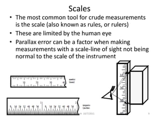

This document provides an overview of engineering metrology and linear measurements. It defines key terms related to dimensional metrology and discusses common measurement tools like scales, calipers, micrometers, and dial indicators. Scales are limited by human error while calipers and micrometers provide more precise linear measurements through vernier or thread mechanisms that magnify small movements. The document also covers measurement best practices and factors that influence tolerance and repeatability.