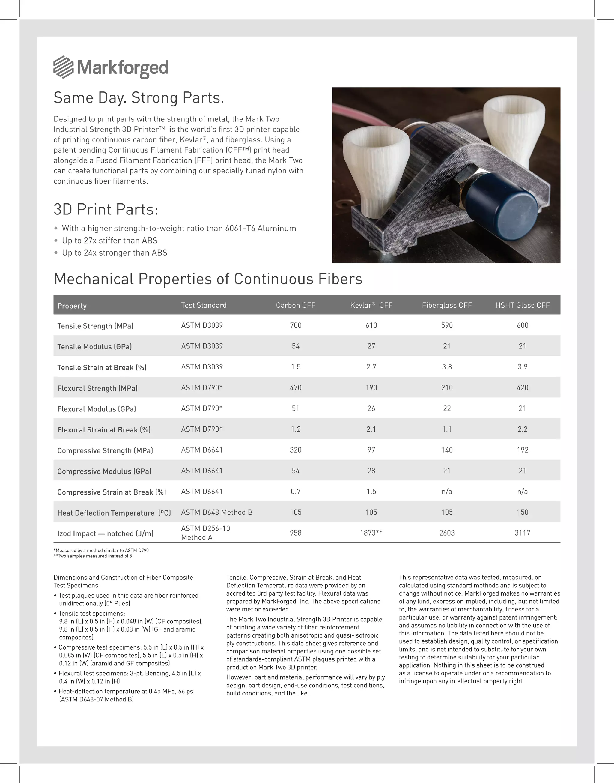
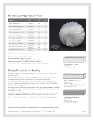
Dimensions and Construction of Fiber Composite
Test Specimens
• Test plaques used in this data are fiber reinforced
unidirectionally (0° Plies)
• Tensile test specimens:
9.8 in (L) x 0.5 in (H) x 0.048 in (W) (CF composites),
9.8 in (L) x 0.5 in (H) x 0.08 in (W) (GF and aramid
composites)
• Compressive test specimens: 5.5 in (L) x 0.5 in (H) x
0.085 in (W) (CF composites), 5.5 in (L) x 0.5 in (H) x
0.12 in (W) (aramid and GF composites)
• Flexural test specimens: 3-pt. Bending, 4.5 in (L) x
0.4 in (W) x 0.12 in (H)
• Heat-deflection temperature at 0.45 MPa, 66 psi
(ASTM D648-07 Method B)
Tensile, Compressive, Strain at Break, and Heat
Deflection Temperature data were provided by an
accredited 3rd party test facility. Flexural data was
prepared by MarkForged, Inc. The above specifications
were met or exceeded.
The Mark Two Industrial Strength 3D Printer is capable
of printing a wide variety of fiber reinforcement
patterns creating both anisotropic and quasi-isotropic
ply constructions. This data sheet gives reference and
comparison material properties using one possible set
of standards-compliant ASTM plaques printed with a
production Mark Two 3D printer.
However, part and material performance will vary by ply
design, part design, end-use conditions, test conditions,
build conditions, and the like.
This representative data was tested, measured, or
calculated using standard methods and is subject to
change without notice. MarkForged makes no warranties
of any kind, express or implied, including, but not limited
to, the warranties of merchantability, fitness for a
particular use, or warranty against patent infringement;
and assumes no liability in connection with the use of
this information. The data listed here should not be
used to establish design, quality control, or specification
limits, and is not intended to substitute for your own
testing to determine suitability for your particular
application. Nothing in this sheet is to be construed
as a license to operate under or a recommendation to
infringe upon any intellectual property right.
*Measured by a method similar to ASTM D790
**Two samples measured instead of 5
Same Day. Strong Parts.
Designed to print parts with the strength of metal, the Mark Two
Industrial Strength 3D Printer™ is the world’s first 3D printer capable
of printing continuous carbon fiber, Kevlar®
, and fiberglass. Using a
patent pending Continuous Filament Fabrication (CFF™) print head
alongside a Fused Filament Fabrication (FFF) print head, the Mark Two
can create functional parts by combining our specially tuned nylon with
continuous fiber filaments.
3D Print Parts:
•	 With a higher strength-to-weight ratio than 6061-T6 Aluminum
•	 Up to 27x stiffer than ABS
•	 Up to 24x stronger than ABS
Property Test Standard Carbon CFF Kevlar®
CFF Fiberglass CFF HSHT Glass CFF
Tensile Strength (MPa) ASTM D3039 700 610 590 600
Tensile Modulus (GPa) ASTM D3039 54 27 21 21
Tensile Strain at Break (%) ASTM D3039 1.5 2.7 3.8 3.9
Flexural Strength (MPa) ASTM D790* 470 190 210 420
Flexural Modulus (GPa) ASTM D790* 51 26 22 21
Flexural Strain at Break (%) ASTM D790* 1.2 2.1 1.1 2.2
Compressive Strength (MPa) ASTM D6641 320 97 140 192
Compressive Modulus (GPa) ASTM D6641 54 28 21 21
Compressive Strain at Break (%) ASTM D6641 0.7 1.5 n/a n/a
Heat Deflection Temperature (ºC) ASTM D648 Method B 105 105 105 150
Izod Impact — notched (J/m)
ASTM D256-10
Method A
958 1873** 2603 3117
Mechanical Properties of Continuous Fibers
© MarkForged, Inc. 2016. All rights reserved. Kevlar®
is a registered trademark of DuPont E.I. du Pont de Nemours and Company or its affiliates.
printstronger@markforged.com +1 617.666.1935 06.20.16markforged.com
Mechanical Properties of Nylon
Property
Test
Standard
Tough
Nylon
Onyx
Tensile Modulus (GPa) ASTM D638 0.94 1.4
Tensile Stress at Yield (MPa) ASTM D638 31 36
Tensile Strain at Yield (%) ASTM D638 27 25
Tensile Stress at Break (MPa) ASTM D638 54 30
Tensile Strain at Break (%) ASTM D638 260 58
Flexural Strength (MPa) ASTM D790* 32 81
Flexural Modulus (GPa) ASTM D790* 0.84 2.9
Flexural Strain at Break (%) ASTM D790* n/a n/a
Heat Deflection Temperature (ºC)
ASTM D648
Method B
49
140† 145
Izod Impact — notched (J/m)
ASTM D256-10
Method A
1015 334
Design Principles for Bending
Markforged CFF™ technology reinforces 3D plastic parts with 10x stronger and 20x stiffer
continuous fibers.
The above Material Properties therefore are combined in a part automatically by our Eiger
software (although users may also customized the fiber distribution per layer).
In automatic mode, Markforged’s Eiger software defaults to creating embedded Sandwich
Panels — well-known reinforced structures widely used in aerospace and construction that
provide excellent bending performance.
Overall part stiffness and strength, represented by tensile and compressive Material Properties
above, depends very much upon fiber content, and is strongly related to the amount of fiber the
user chooses for a part.
However, per engineering sandwich theory, flexural or bending performance tends to benefit
strongly from modest reinforcement in a sandwich panel form (see images on the right).
For more information, please our more detailed “Thermomechanical Stability” white paper.
127 layer HSHT Sandwich Beam:
(not to scale)
117 layers nylon,
10 layers HSHT Glass CFF (~10% by vol.)
Heat Deflection: 140 °C
127 layer HSHT Filled Beam:
(not to scale)
2 layers Nylon,
125 layers HSHT Glass CFF:
Heat Deflection: 150 °C
127 layer Nylon FFF Beam:
(not to scale)
Heat Deflection: 49 °C
Dimensions and Construction of Plastic Test Specimens
• Tensile test specimens: ASTM D638 type IV beams
• Flexural test specimens: 3-pt. Bending, 4.5 in (L) x 0.4 in (W) x 0.24 in (H)
• Heat-deflection temperature at 0.45 MPa, 66 psi (ASTM D648-07 Method B)
• Flexural Strain at Break is not available because nylon does not break before the test ends
*Measured by a method similar to ASTM D790
†
Heat deflection temperature of a beam with less than 10% HSHT Glass added, see below for details

MarkForged: Mark Two materials

  • 1.
    Dimensions and Constructionof Fiber Composite Test Specimens • Test plaques used in this data are fiber reinforced unidirectionally (0° Plies) • Tensile test specimens: 9.8 in (L) x 0.5 in (H) x 0.048 in (W) (CF composites), 9.8 in (L) x 0.5 in (H) x 0.08 in (W) (GF and aramid composites) • Compressive test specimens: 5.5 in (L) x 0.5 in (H) x 0.085 in (W) (CF composites), 5.5 in (L) x 0.5 in (H) x 0.12 in (W) (aramid and GF composites) • Flexural test specimens: 3-pt. Bending, 4.5 in (L) x 0.4 in (W) x 0.12 in (H) • Heat-deflection temperature at 0.45 MPa, 66 psi (ASTM D648-07 Method B) Tensile, Compressive, Strain at Break, and Heat Deflection Temperature data were provided by an accredited 3rd party test facility. Flexural data was prepared by MarkForged, Inc. The above specifications were met or exceeded. The Mark Two Industrial Strength 3D Printer is capable of printing a wide variety of fiber reinforcement patterns creating both anisotropic and quasi-isotropic ply constructions. This data sheet gives reference and comparison material properties using one possible set of standards-compliant ASTM plaques printed with a production Mark Two 3D printer. However, part and material performance will vary by ply design, part design, end-use conditions, test conditions, build conditions, and the like. This representative data was tested, measured, or calculated using standard methods and is subject to change without notice. MarkForged makes no warranties of any kind, express or implied, including, but not limited to, the warranties of merchantability, fitness for a particular use, or warranty against patent infringement; and assumes no liability in connection with the use of this information. The data listed here should not be used to establish design, quality control, or specification limits, and is not intended to substitute for your own testing to determine suitability for your particular application. Nothing in this sheet is to be construed as a license to operate under or a recommendation to infringe upon any intellectual property right. *Measured by a method similar to ASTM D790 **Two samples measured instead of 5 Same Day. Strong Parts. Designed to print parts with the strength of metal, the Mark Two Industrial Strength 3D Printer™ is the world’s first 3D printer capable of printing continuous carbon fiber, Kevlar® , and fiberglass. Using a patent pending Continuous Filament Fabrication (CFF™) print head alongside a Fused Filament Fabrication (FFF) print head, the Mark Two can create functional parts by combining our specially tuned nylon with continuous fiber filaments. 3D Print Parts: • With a higher strength-to-weight ratio than 6061-T6 Aluminum • Up to 27x stiffer than ABS • Up to 24x stronger than ABS Property Test Standard Carbon CFF Kevlar® CFF Fiberglass CFF HSHT Glass CFF Tensile Strength (MPa) ASTM D3039 700 610 590 600 Tensile Modulus (GPa) ASTM D3039 54 27 21 21 Tensile Strain at Break (%) ASTM D3039 1.5 2.7 3.8 3.9 Flexural Strength (MPa) ASTM D790* 470 190 210 420 Flexural Modulus (GPa) ASTM D790* 51 26 22 21 Flexural Strain at Break (%) ASTM D790* 1.2 2.1 1.1 2.2 Compressive Strength (MPa) ASTM D6641 320 97 140 192 Compressive Modulus (GPa) ASTM D6641 54 28 21 21 Compressive Strain at Break (%) ASTM D6641 0.7 1.5 n/a n/a Heat Deflection Temperature (ºC) ASTM D648 Method B 105 105 105 150 Izod Impact — notched (J/m) ASTM D256-10 Method A 958 1873** 2603 3117 Mechanical Properties of Continuous Fibers
  • 2.
    © MarkForged, Inc.2016. All rights reserved. Kevlar® is a registered trademark of DuPont E.I. du Pont de Nemours and Company or its affiliates. printstronger@markforged.com +1 617.666.1935 06.20.16markforged.com Mechanical Properties of Nylon Property Test Standard Tough Nylon Onyx Tensile Modulus (GPa) ASTM D638 0.94 1.4 Tensile Stress at Yield (MPa) ASTM D638 31 36 Tensile Strain at Yield (%) ASTM D638 27 25 Tensile Stress at Break (MPa) ASTM D638 54 30 Tensile Strain at Break (%) ASTM D638 260 58 Flexural Strength (MPa) ASTM D790* 32 81 Flexural Modulus (GPa) ASTM D790* 0.84 2.9 Flexural Strain at Break (%) ASTM D790* n/a n/a Heat Deflection Temperature (ºC) ASTM D648 Method B 49 140† 145 Izod Impact — notched (J/m) ASTM D256-10 Method A 1015 334 Design Principles for Bending Markforged CFF™ technology reinforces 3D plastic parts with 10x stronger and 20x stiffer continuous fibers. The above Material Properties therefore are combined in a part automatically by our Eiger software (although users may also customized the fiber distribution per layer). In automatic mode, Markforged’s Eiger software defaults to creating embedded Sandwich Panels — well-known reinforced structures widely used in aerospace and construction that provide excellent bending performance. Overall part stiffness and strength, represented by tensile and compressive Material Properties above, depends very much upon fiber content, and is strongly related to the amount of fiber the user chooses for a part. However, per engineering sandwich theory, flexural or bending performance tends to benefit strongly from modest reinforcement in a sandwich panel form (see images on the right). For more information, please our more detailed “Thermomechanical Stability” white paper. 127 layer HSHT Sandwich Beam: (not to scale) 117 layers nylon, 10 layers HSHT Glass CFF (~10% by vol.) Heat Deflection: 140 °C 127 layer HSHT Filled Beam: (not to scale) 2 layers Nylon, 125 layers HSHT Glass CFF: Heat Deflection: 150 °C 127 layer Nylon FFF Beam: (not to scale) Heat Deflection: 49 °C Dimensions and Construction of Plastic Test Specimens • Tensile test specimens: ASTM D638 type IV beams • Flexural test specimens: 3-pt. Bending, 4.5 in (L) x 0.4 in (W) x 0.24 in (H) • Heat-deflection temperature at 0.45 MPa, 66 psi (ASTM D648-07 Method B) • Flexural Strain at Break is not available because nylon does not break before the test ends *Measured by a method similar to ASTM D790 † Heat deflection temperature of a beam with less than 10% HSHT Glass added, see below for details