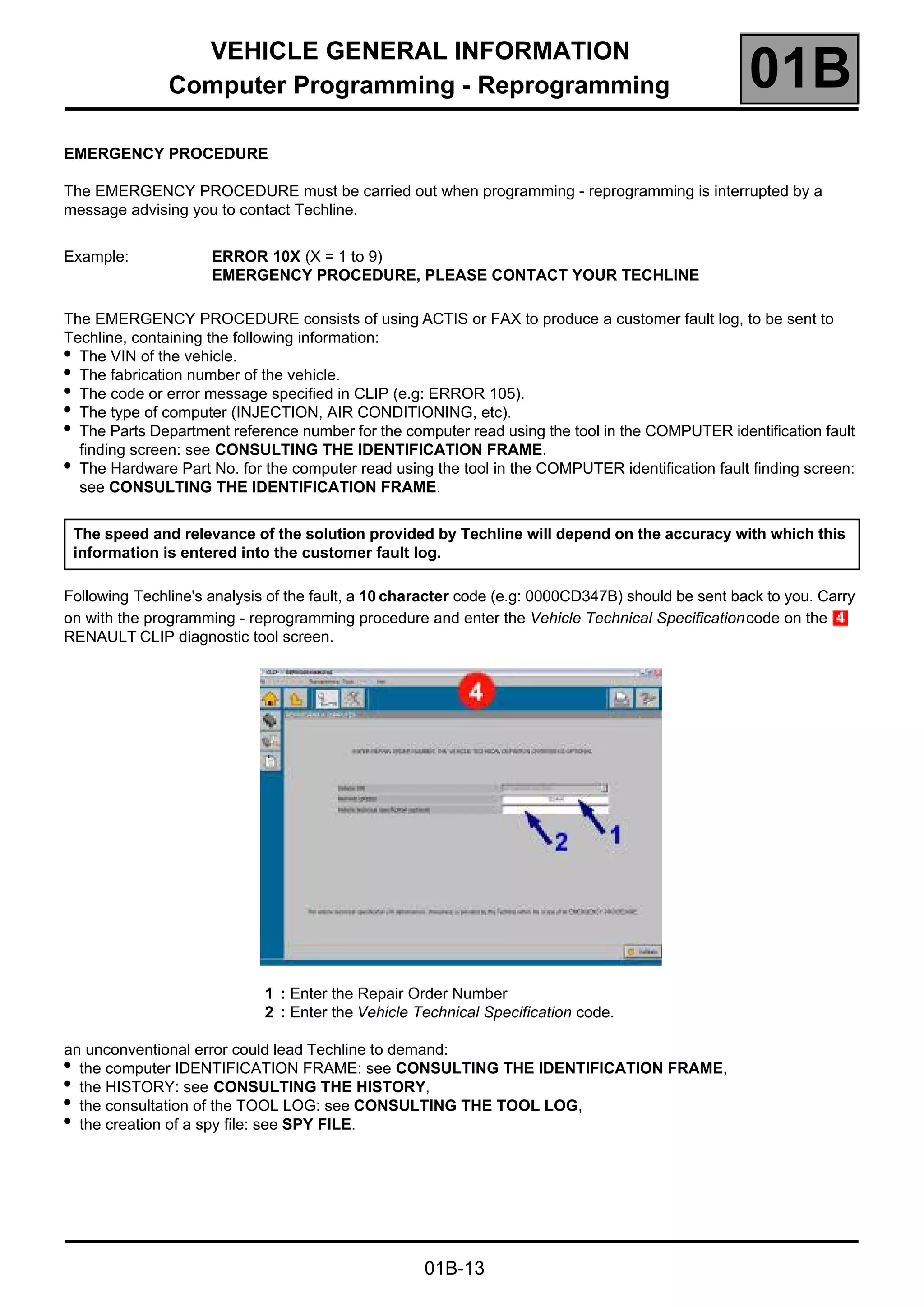
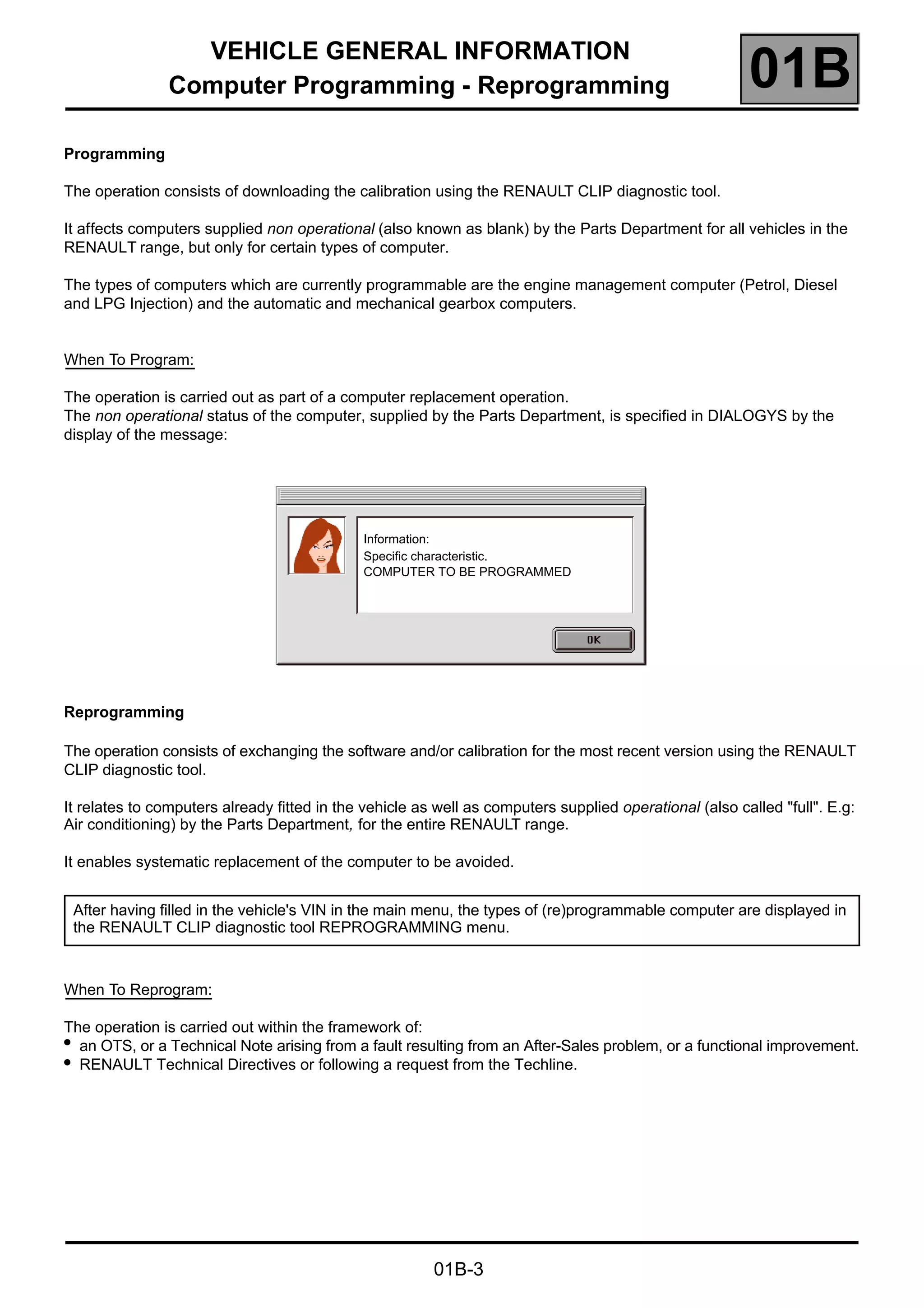
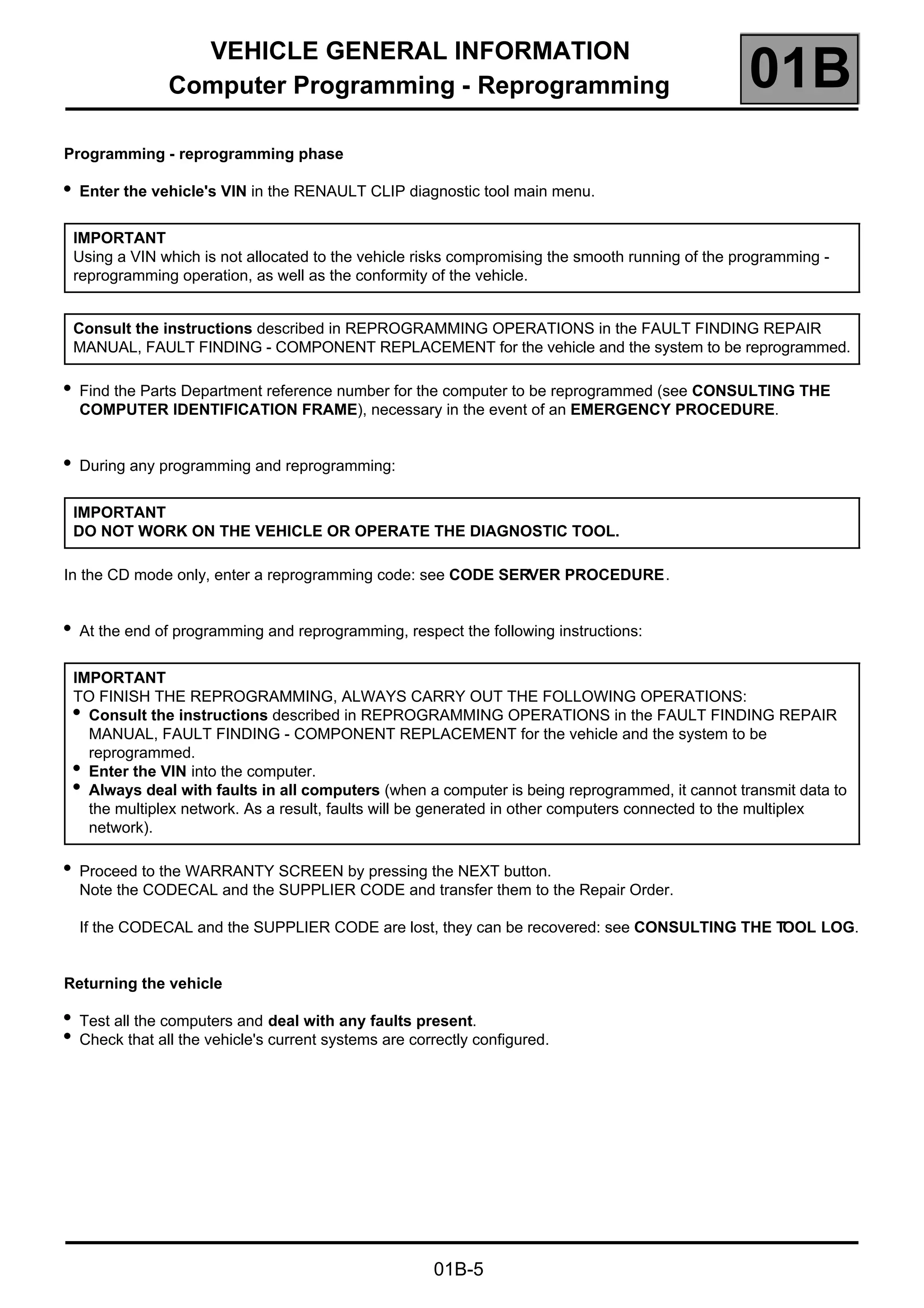
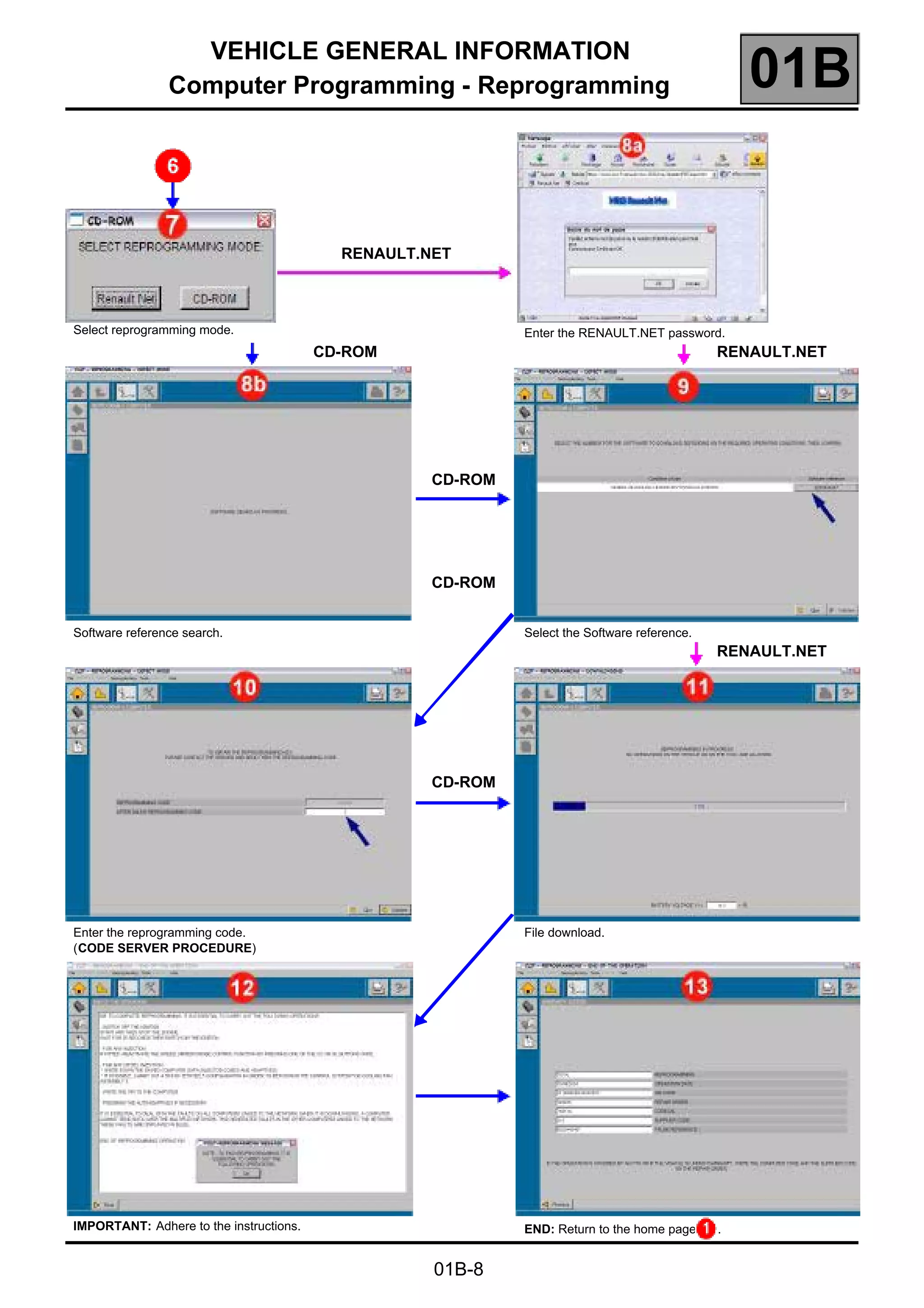
This document provides instructions for programming and reprogramming vehicle onboard computers using a Renault CLIP diagnostic tool connected to Renault.NET or a reprogramming CD. Key steps include preparing the diagnostic tool and vehicle, entering the vehicle identification number, selecting the computer to program/reprogram, and obtaining codes to validate the repair at completion. Errors are possible, and emergency procedures are provided to address issues that may occur.
JULIE Emulator New Universal IMMO Emulator for CAN-BUS Cars
Support more brand vehicles
Applicable to:
Audi, BMW, Chrysler, Citroen, Daewoo, Fiat, Honda, KIA, Mazda, Mercedes, Mini Cooper, Nissan, Opel, Peugeot, Renault, Seat, Suzuki, VW, Yamaha
If use this Emulator for Can-Bus cars, you need solder an 120Ohm resistance on the PCB
This document provides information about the electrical system of a Sinotruk vehicle. It includes 3 sections:
1. An overview of the main electrical parts and their functions.
2. Instructions on how to operate parts like the headlights, fog lights, brake lights, wipers and more.
3. Diagrams of electrical circuits and principles to explain how systems like the headlights, starter, and instruments work. Troubleshooting tips are also provided.
1) O documento fornece instruções para testar e verificar vários sensores e componentes de um sistema de injeção eletrônica, incluindo sensor Hall, sensor MAF, sensor de temperatura do motor e ar, sensor de oxigênio, sensor de velocidade e outros.
2) É fornecida uma tabela com valores de referência para resistência e tensão esperados para cada sensor em diferentes condições.
3) Instruções passo a passo são fornecidas para realizar a regulagem básica do módulo de controle da marcha l
Toyota 1KD-FTV Common Rail Diesel Injector Installation Manual BaileysDieselGroup
This document provides instructions for removing the injectors from a Toyota 1KD-FTV common rail diesel engine. It outlines 21 steps for disassembly, including lifting the bonnet, removing covers and sensors, unplugging injectors, loosening pipes and brackets, and removing the tappet cover. Precautions are recommended when cylinders are exposed. Sections for pre-assembly and assembly can be downloaded from the provided website and Facebook page.
The document describes a Mercedes airbag reset tool that can reset and repair a Mercedes airbag computer in one minute. It allows users to erase crash data and error messages stored in the airbag sensor memory without needing to replace the expensive sensor. The new tool connects via USB and can read/write EEPROM memory, clear crash data and error memory, supporting more Mercedes ECU types than the older serial COM port tool. Diagrams show how to connect the tool to the airbag sensor to erase data either in the car or by disconnecting the sensor from the car.
O documento fornece instruções sobre o sistema de arrefecimento da motocicleta CB500, incluindo diagnóstico de defeitos, fluxo de arrefecimento, drenagem e remoção/instalação de componentes como o reservatório, termostato, radiador e bomba d'água.
The document contains a list of various vehicle service manuals, repair manuals, and technical manuals for automobiles, motorcycles, tractors, snowblowers, and other vehicles from manufacturers such as John Deere, Chevrolet, Ferrari, Nissan, Subaru, Suzuki, Yamaha, and others. The manuals cover a range of vehicle models from the 1940s through the 2000s and include shop manuals, repair manuals, technical manuals, and more.
Este documento proporciona especificaciones eléctricas y de sensores para un motor, así como información sobre códigos de falla incluyendo la lámpara iluminada, razón y efecto. Incluye tablas con valores nominales para componentes eléctricos y sensores, y una lista de códigos de falla que indican el problema detectado y su impacto en el desempeño.
Manual de serviço ms nx 4 falcon - 00 x6b-mcg-002 partidaThiago Huari
Este documento fornece instruções sobre o sistema de partida elétrica de um veículo NX-4 FALCON, incluindo:
1) Diagrama do sistema de partida elétrica e informações sobre diagnóstico de defeitos;
2) Procedimentos para inspeção e reparo do motor de partida;
3) Inspeção e teste do interruptor do relé de partida;
4) Inspeção dos diodos da embreagem e do ponto morto.
Este documento proporciona información sobre la operación y mantenimiento de las camionetas FOTON BJ1036V4AV5-D2. Explica los dispositivos e instrumentos de la cabina, así como los testigos e indicadores del tablero. También describe los procedimientos para el encendido, apagado y conducción del vehículo, e incluye instrucciones sobre inspecciones diarias y rutinas de mantenimiento. El objetivo es que los usuarios operen y mantengan correctamente sus camionetas para garantizar la seguridad y prolongar
Manual de serviço xlr125 00 x6b-kfc-601 diagramaThiago Huari
Este manual técnico descreve os procedimentos de manutenção e serviço para a motocicleta XLR125. Ele contém informações gerais sobre a motocicleta, instruções de como usar o manual, e um índice geral dos sistemas cobertos nos capítulos seguintes.
Este documento fornece instruções para diagnosticar defeitos e realizar serviços no cilindro e pistão de uma motocicleta. Ele descreve como remover e instalar o cilindro e pistão, bem como especificações e limites de uso para essas peças.
This document provides information about NC and CNC machines. It discusses the differences between NC and CNC, describing how programs are fed into each type of machine. It also lists and defines common types of machining centers such as horizontal and vertical machining centers. The document then covers the layout and basic operation of turning centers and milling centers. It explains ladder programming and addresses used in ladder diagrams.
1990-2001 Johnson Evinrude Outboard Service Manual - 1 HP to 300 HPevinrudejohnson
This document provides information about service manuals for Johnson and Evinrude outboard motors from 1973 to 2001 covering horsepower ratings from 1 to 300 HP. It includes summaries of service manuals for 2-stroke and 4-stroke outboard motors and sea drive models from various years. It also includes a list of common questions asked about servicing, repairing, and operating Johnson and Evinrude outboard motors from the 1980s to 2000s.
Este documento proporciona información general sobre el mantenimiento preventivo de camiones Volvo. Incluye consejos de seguridad, especificaciones de componentes, herramientas necesarias e instrucciones para la inspección básica que se lleva a cabo cada 24,000 km o 4 meses. También menciona inspecciones adicionales basadas en el kilometraje o el tiempo, y la importancia de llevar registros de mantenimiento.
Manual de serviço cb500 00 x6b-my5-001 diagramaThiago Huari
Este manual técnico descreve os procedimentos de manutenção e serviço para a motocicleta Honda CB500, incluindo informações gerais, tabela de manutenção, diagnóstico de problemas e diagramas elétricos. O documento é dividido em seções cobrindo os principais sistemas do veículo.
This document provides information for diagnosing electrical failures, including performing efficient diagnosis, simulating failure conditions, handling electrical components safely, and checking connectors. Key steps include obtaining details on the failure, inspecting for physical issues, using diagrams to determine involved circuits, repairing or replacing components, and verifying the system works properly under all conditions. Failure simulations include tests for vehicle vibration, heat, freezing, water intrusion, electrical load changes, and cold/hot starts.
This document provides specifications and connector locations for components in the electrical system of a vibratory compactor. It includes two charts: one listing component locations by schematic symbol and machine location, and one listing connector locations by number, schematic symbol, and machine location. It also provides specifications for several switches, including actuation/deactuation parameters and contact positions. Related manuals are referenced. The information is intended to aid in understanding and working on the machine's electrical system.
Ford 6600 tractor service repair manualfiskefksjemkm
This short document provides a link and instructions for downloading a manual. It thanks the reader for reading and asks them to click the link to access the complete manual without waiting. It notes that if the link does not work, the reader should first download the PDF document and then click on it to open the manual.
BUENO DE UN ARCHIVO EN POWER POINT EL TEMA SISTEMA DE HPCR LA CUAL ES UN SISTEMA DE FUNCIONAMIENTO DE MOTOR. ESPERO LES INTERESE. Y TAMBIÉN AYUDE A TODOS LO MECÁNICOS .
Jcb 155 skid steer loader service repair manual (from 2473501 to 2473800)fdjjsekksemxs
This service manual provides information for servicing a JCB skid steer loader engine. It contains sections on general engine information, components, operation, maintenance, troubleshooting and repair. Safety precautions are outlined and technical specifications provided. The document provides instructions to correctly service the engine and ensure it operates safely and efficiently.
Este documento proporciona información sobre un nuevo cambio automático de 5 velocidades para vehículos Volkswagen y Audi. Describe la configuración básica del cambio, incluyendo la palanca selectora, la unidad de control, el convertidor de par y los engranajes planetarios. También explica cómo los embragues y frenos conectan las marchas al abrir y cerrar.
This document provides locations for various components, circuits, and connectors on 2009 Jeep Compass and Patriot vehicles. It lists the component name, location description, and figure number showing where the component can be found. Components include relays, fuses, control modules, motors, sensors, solenoids, switches, grounds, splices and connectors. Each is described in terms of its location such as in the engine compartment, under the dash, on the body, or in a specific area like the driver's door.
This document provides a summary of a vehicle electrical schematic. It includes a list of common wire colors and their electrical functions. Additionally, it describes the various input and output connections for different vehicle systems that are routed through the chassis node box and CAN networks. Abbreviations are provided for various vehicle components and systems.
This document provides information about inspecting and repairing an automatic transaxle. It begins with safety precautions for working with compressed air and cleaning fluids. It describes the components and systems of the automatic transaxle in detail. Troubleshooting procedures are outlined in a step-by-step process beginning with verifying the customer's problem and ending with a confirmation test after repairs. Road tests and mechanical system tests are described to check the performance of the transaxle.
This document provides location information for various components, modules, relays, and fuses for a 2005 Saturn L300. It lists over 50 components and their locations, organized into sections for relays, fuse blocks, control modules, motors/sensors, and connectors. Diagrams referenced for many components provide further details on their exact location within the vehicle.
Este documento fornece instruções para desmontagem e manutenção do sistema de alimentação de um veículo. Ele inclui informações sobre:
- Remoção e instalação dos componentes do sistema de alimentação como o carburador, filtros de ar e tanque de combustível.
- Diagnóstico de defeitos comuns no sistema de alimentação.
- Desmontagem e verificação de componentes internos do carburador como a câmara de vácuo, válvula de corte de ar e cuba da bóia.
AUDI A4 B5 1.8L 1996 ELECTRICAL EQUIPMENT 01 1 instrument cluster, on board d...Gherghescu Gabriel
The document discusses the Audi A4 instrument cluster, which comes in two versions - a basic version with a mini-check system or a high-line version with a multi-function LCD display. The instrument cluster is controlled by a microprocessor and can store diagnostic trouble codes. Using a scan tool, technicians can check the diagnostic trouble code memory, perform diagnostic tests, erase codes, code new control modules, and perform adaptations like setting the odometer after replacing the instrument cluster. The document provides details on initiating these scan tool functions and interpreting diagnostic trouble codes.
AUDI A4 B5 1.8L 1996 ELECTRICAL EQUIPMENT 01 84 multi-function steering wheel...Gherghescu Gabriel
The document provides instructions for using an On Board Diagnostic (OBD) tool to test the functions of a vehicle's multi-function steering wheel and diagnose any issues. It describes connecting the tool, navigating the tool's menu to select diagnostic tests, performing tests of steering wheel controls and reading trouble codes, and erasing fault memories after repairs. Safety notes are also provided to caution operating the tool from the rear seat during a road test.
AUDI A4 B5 1.8L 1996 ELECTRICAL EQUIPMENT 01 79 instrument cluster, on board ...Gherghescu Gabriel
The instrument cluster in Audi vehicles evaluates various vehicle service requirements based on input data. It can also process flexible data to reproduce standard functions when limits are set correctly. The cluster has extensive OBD capabilities to diagnose faults in other vehicle systems. When issues occur, diagnostic trouble codes are stored and can be retrieved using a scan tool to help locate the problem.
This document provides information about using a Nanocom Evolution diagnostic tool to access different models of Land Rover Defender vehicles, specifically the 2.4L and 2.2L diesel "Puma" models from 2007-2015. It details the engine control units, ABS systems, alarm systems, and available diagnostic functions for each vehicle. These include reading and clearing fault codes, viewing live engine data and sensor inputs, and accessing certain component settings. Additional resources for support documentation and forums are also listed.
This document describes an upcoming webinar series on advanced machinery telematics. Each webinar will focus on a different topic related to advanced telematics systems for complex vehicles and machinery. The webinars will last 30 minutes and include examples from Technoton projects. The first webinar will provide an introduction and overview of advanced telematics, differences from regular vehicle tracking, and Technoton's product portfolio. Subsequent webinars will dive deeper into topics such as fuel sensors, gateways and displays, and example implementations for ships, tanker trucks, and generator stations.
ATEQ Quickset TPMS Reset Relearn Tool User ManualTim Miller
This is the user manual of the ATEQ Quickset TPMS tool.
>> READ MORE: https://www.obdadvisor.com/best-tpms-tool-review/
Here is a detailed review of the best TPMS tools based on my own experience, including:
- Compatibility
- Features and Functions
- Pros and Cons
Check it out to get the REVIEW and some NOTES about using the tool.
Variable speed drives control motor speed and torque by converting AC electricity from mains supply. Drives require a speed demand signal and feedback from motor sensors to run control algorithms. Drives are tuned to match the motor and load conditions for optimal speed maintenance. Variable speed drives can be programmed either using the drive's internal function blocks or programming blocks in a PLC. Using internal blocks is often quicker but requires learning proprietary software, while PLC programming is more flexible but more complex and resource-intensive. The best approach depends on the application and expertise of the engineering team.
The TomTom LINK 105 is a small device that installs easily into light commercial vehicles through the OBD-II port. It monitors key vehicle data like fuel efficiency, emissions, engine trouble codes, and sends this information to the WEBFLEET system. WEBFLEET then provides reports and dashboards that give insights into reducing fuel and maintenance costs, and improving fleet efficiency and driver behavior. The LINK 105 is a simple, effective way to access important vehicle information.
This document provides instructions for using the iCarsoft diagnostic tool or CR Plus. It outlines safety precautions, explains diagnostic functions like reading and clearing codes, and provides guidance on connecting the tool, navigating menus, updating software, and diagnosing vehicle systems.
This is the user manual of iCarsoft CR+.
>> READ MORE: https://www.obdadvisor.com/icarsoft-por-ii/
Here is a detailed review of the scan tool based on my own experience, including:
- Compatibility
- Hardware and Design
- Features and Functions
- Pros and Cons
Check it out to get the REVIEW and some NOTES about using this scanner.
This is the user manual of iCarsoft MBII.
>> READ MORE: https://www.obdadvisor.com/icarsoft-por-ii/
Here is a detailed review of the scan tool based on my own experience, including:
- Compatibility
- Hardware and Design
- Features and Functions
- Pros and Cons
Check it out to get the REVIEW and some NOTES about using this scanner.
Our Customer (an Automotive Tier-I Supplier) encountered a major roadblock during software porting.Due to limited on-chip memory (RAM and ROM) of DsPIC 30F4011 platform, it became imperative for the customer to port highly-optimized embedded software to the EPS system.
Find out how a re-usable SAE J1939 compliant stack, best suited for commercial vehicles, was integrated with the EPS system to resolve the issue
Cgdi prog bmw obd program fem key - obd2diy.frMou Dawei
The current FEM/BDC needs to update the ECU program before performing key matching. Please ensure that the car battery has enough power, the programming process, please keep the equipment cable connection
AUDI A4 B5 1.8L 1996 ELECTRICAL EQUIPMENT 01 1 radio obdGherghescu Gabriel
The document provides instructions for using an onboard diagnostic (OBD) tool to test the radio system in Audi vehicles from 1998. It describes how to initiate the OBD program using the tool, select functions to check diagnostic trouble codes (DTCs), erase the DTC memory, and perform output tests. The document also includes a table listing possible DTCs, their meanings, and the corrective actions to address any issues found.
Veepeak OBDCheck VP30 User Manual
>> READ MORE: https://www.obdadvisor.com/best-veepeak-obd2-scanner-review/
Here is a detailed review of the Veepeak OBD2 adapters:
- Features and functions
- Compatibility
- Pros and cons
Check it out to get the REVIEW and some NOTES about using this scanner based on my own experience.
This document provides information about accessing the owner's manual for a Peugeot vehicle. It explains that the manual can be found online on the Peugeot website under the "Personal space" section. It also provides an alternate web address to access the manual if the "Personal space" function is unavailable in the user's country. The document emphasizes that the latest information will be available online and identified by a bookmark symbol.
Himanth Kumar Doddi is an automotive embedded developer with over 8 years of experience developing embedded software. He has expertise in C programming, real-time operating systems, automotive protocols like CAN and J1939, and software tools including CANalyzer, AllSim and Greenhill. Some of his project experience includes developing radio control software for vehicles, seeding machine software, payment processing devices, and marine instrument display software.
AUDI A4 B5 1.8L 1996 BADY ODB 01 69 central locking system obdGherghescu Gabriel
The document provides information about the central locking system onboard diagnostic (OBD) functions for Audi vehicles, including:
1. The central locking system has two pneumatic circuits that control different locking points and can be operated using the VAG1551 scan tool for diagnostics.
2. The scan tool can be used to check the control module version, diagnostic trouble codes (DTC) memory, initiate diagnostic test modes, code the control module, and read measuring value blocks to diagnose issues.
3. A DTC table lists potential codes that may appear when checking the DTC memory and provides troubleshooting steps to resolve common problems like short circuits.
Innova 3123 GM OBD1 Code Reader User ManualTim Miller
Innova 3123 Owner’s Manual
>> READ MORE: https://www.obdadvisor.com/innova-3123-gm-review/
Here is a detailed review of the Innova 3123 scan tool based on my own experience:
- Compatibility
- Display
- Software
- Features and Functionality
Check it out to get the REVIEW and some NOTES about using this scanner based on my own experience.
The P2209 trouble code indicates a problem with the nitrogen oxide (NOx) sensor in the catalytic converter. This sensor measures nitric oxide and nitrogen oxide in the exhaust. When the NOx sensor reaches its storage capacity, it triggers regeneration of the fuel management system. The code is set when the sensor's voltage reading is abnormal. Potential causes include a faulty NOx sensor, wiring issues, or a poor electrical connection. Recommended repairs include fixing exhaust leaks, replacing fuel system components, the catalytic converter, oxygen sensor, or sensors related to air and coolant monitoring. It is best to service the problem soon to prevent further damage.
The document provides information on various BMW engine control units (ECUs) including Bosch Motronic and Siemens MS ECUs. It summarizes the engines and vehicle models that different ECU versions were used in, as well as some of their key features like adding variable valve timing (VANOS) or emissions monitoring capabilities. The document also lists typical diagnostic trouble codes for some common ECUs.
The document lists diagnostic trouble codes (DTCs) for Mercedes-Benz models from 1996 onwards. It includes over 400 powertrain-related DTCs covering issues with sensors, emissions components, fuel and ignition systems. The DTCs are organized by system and provide details on malfunctions, out of range values and intermittent faults that can be retrieved from the vehicle's onboard computer.
Sistemadecontrolelectrnicodieseledc16 121213200122-phpapp01Boualam Mohammed
El documento describe el sistema de gestión electrónica Bosch EDC 16 utilizado en el motor diesel TDI V10. El sistema EDC 16 utiliza dos unidades de control del motor, una para cada bancada de cilindros, que recopilan datos de sensores y controlan actuadores para gestionar funciones como la inyección de combustible, la sobrealimentación y la recirculación de gases de escape. El sistema responde a las demandas cada vez mayores de rendimiento, consumo y emisiones de los motores diésel modernos.
Este documento proporciona información técnica sobre el cableado y especificaciones de un Honda Jazz SC667051 (MPC5604P) 0M26V, incluyendo detalles sobre las conexiones de señales TDI, TDO, TCK, TMS, RESET y GND, así como la necesidad de un suministro de alimentación de 12V/2A para probar el dispositivo. También se proporciona información sobre el fabricante y la fecha de revisión.
Este documento proporciona información sobre un controlador de airbag SPC560P50L3 de Renault. Incluye detalles sobre las conexiones de entrada y salida del controlador como TDI, TDO, TCK, RESET y alimentación Vdd, así como la referencia del producto, fecha de revisión y sitio web del fabricante.
The document lists diagnostic trouble codes (DTCs) for Mercedes-Benz models from 1996 onwards. It includes over 400 powertrain-related DTCs covering issues with sensors, emissions components, fuel and ignition systems. The DTCs are organized by system and provide details on malfunctions, out of range values and intermittent faults that can be retrieved from the vehicle's onboard computer.
087 servodireccion-electrohidraulicapdf1530-111005123534-phpapp01Boualam Mohammed
Este documento proporciona una sinopsis del sistema de servodirección electrohidráulica. Explica que utiliza un motor eléctrico para accionar una bomba hidráulica que proporciona asistencia variable en la dirección en función de la velocidad del vehículo y la rapidez de giro del volante. También describe los componentes electrónicos, mecánicos e hidráulicos del sistema y cómo funcionan para proporcionar asistencia en la dirección.
This document refers to an automotive part for a Nissan Megane II vehicle, specifically a microcontroller unit with the model number MC9S12DT256 and mask number 4L91N. The part is used to control various systems in the Megane II.
Fleet management these days is next to impossible without connected vehicle solutions. Why? Well, fleet trackers and accompanying connected vehicle management solutions tend to offer quite a few hard-to-ignore benefits to fleet managers and businesses alike. Let’s check them out!
Implementing ELDs or Electronic Logging Devices is slowly but surely becoming the norm in fleet management. Why? Well, integrating ELDs and associated connected vehicle solutions like fleet tracking devices lets businesses and their in-house fleet managers reap several benefits. Check out the post below to learn more.
What Could Be Behind Your Mercedes Sprinter's Power Loss on Uphill RoadsSprinter Gurus
Unlock the secrets behind your Mercedes Sprinter's uphill power loss with our comprehensive presentation. From fuel filter blockages to turbocharger troubles, we uncover the culprits and empower you to reclaim your vehicle's peak performance. Conquer every ascent with confidence and ensure a thrilling journey every time.
Welcome to ASP Cranes, your trusted partner for crane solutions in Raipur, Chhattisgarh! With years of experience and a commitment to excellence, we offer a comprehensive range of crane services tailored to meet your lifting and material handling needs.
At ASP Cranes, we understand the importance of reliable and efficient crane operations in various industries, from construction and manufacturing to logistics and infrastructure development. That's why we strive to deliver top-notch solutions that enhance productivity, safety, and cost-effectiveness for our clients.
Our services include:
Crane Rental: Whether you need a crawler crane for heavy lifting or a hydraulic crane for versatile operations, we have a diverse fleet of well-maintained cranes available for rent. Our rental options are flexible and can be customized to suit your project requirements.
Crane Sales: Looking to invest in a crane for your business? We offer a wide selection of new and used cranes from leading manufacturers, ensuring you find the perfect equipment to match your needs and budget.
Crane Maintenance and Repair: To ensure optimal performance and safety, regular maintenance and timely repairs are essential for cranes. Our team of skilled technicians provides comprehensive maintenance and repair services to keep your equipment running smoothly and minimize downtime.
Crane Operator Training: Proper training is crucial for safe and efficient crane operation. We offer specialized training programs conducted by certified instructors to equip operators with the skills and knowledge they need to handle cranes effectively.
Custom Solutions: We understand that every project is unique, which is why we offer custom crane solutions tailored to your specific requirements. Whether you need modifications, attachments, or specialized equipment, we can design and implement solutions that meet your needs.
At ASP Cranes, customer satisfaction is our top priority. We are dedicated to delivering reliable, cost-effective, and innovative crane solutions that exceed expectations. Contact us today to learn more about our services and how we can support your project in Raipur, Chhattisgarh, and beyond. Let ASP Cranes be your trusted partner for all your crane needs!
The Octavia range embodies the design trend of the Škoda brand: a fusion of
aesthetics, safety and practicality. Whether you see the car as a whole or step
closer and explore its unique features, the Octavia range radiates with the
harmony of functionality and emotion
2. VEHICLE GENERAL INFORMATION
Computer Programming - Reprogramming 01B
01B-1
101BVEHICLE GENERAL INFORMATION
Computer Programming - Reprogramming
CONTENTS
Page
GENERAL INFORMATION..........................................................................................................................................2
Tooling required .......................................................................................................................................................2
Programming............................................................................................................................................................3
Reprogramming........................................................................................................................................................3
OPERATING PROCEDURE (Programming and reprogramming a computer)............................................................4
Preparing the RENAULT CLIP diagnostic tool .........................................................................................................4
Preparing the vehicle................................................................................................................................................4
Programming - reprogramming phase......................................................................................................................5
Returning the vehicle................................................................................................................................................5
CLIP screens depending on programming - reprogramming step............................................................................6
Order of the screens.................................................................................................................................................7
CLIP SCREEN ERROR MESSAGES AND PROCEDURE TO FOLLOW ...................................................................9
CODE SERVER PROCEDURE (in CD mode only)...................................................................................................12
EMERGENCY PROCEDURE ...................................................................................................................................13
CONSULTING THE COMPUTER IDENTIFICATION FRAME...................................................................................14
CONSULTING THE COMPUTER'S HISTORY ..........................................................................................................14
CONSULTING THE DIAGNOSTIC TOOL LOG ........................................................................................................15
SPY FILE (upon the request of Techline) ..................................................................................................................16
Creating the spy file................................................................................................................................................16
Recovering the spy file after programming - reprogramming .................................................................................16
3. VEHICLE GENERAL INFORMATION
Computer Programming - Reprogramming 01B
01B-2
GENERAL INFORMATION
Two types of operation can be carried out in After-Sales, either programming or reprogramming of the computer.
These operations apply to all vehicles and all types of (re)programmable computer (e.g: Injection, Gearbox,Air
conditioning, Instrument panel, Parking brake, UCH).
The two types of operation are carried out with the RENAULT CLIP diagnostic tool using either RENAULT.NET, or
the Programming - Reprogramming CD Part No. 77 11 298 859.
The reprogramming data available via RENAULT.NET is always more up to date than that available on the CD
(Part No. 77 11 298 859).
The CD is edited and distributed every month in the same way as the diagnostic tools update.
Each CD cancels and replaces the previous one.
Tooling required
●
CLIP with the most recent update.
●
1 connection to RENAULT.NET (requires a CLIP with a RF kit and a RENAULT.NET certificate)
or
1 reprogramming CD, Part No. 77 11 298 859 from the current month.
●
1 RENAULT approved battery charger.
●
The FAULT FINDING REPAIR MANUAL relevant to the vehicle and the system to be (re)programmed.
●
1 RENAULT.NET connection to the NRE reprogramming codes server for each programming - reprogramming with
a reprogramming CD. See CODES SERVER PROCEDURE.
4. VEHICLE GENERAL INFORMATION
Computer Programming - Reprogramming 01B
01B-3
Programming
The operation consists of downloading the calibration using the RENAULT CLIP diagnostic tool.
It affects computers supplied non operational (also known as blank) by the Parts Department for all vehicles in the
RENAULT range, but only for certain types of computer.
The types of computers which are currently programmable are the engine management computer (Petrol, Diesel
and LPG Injection) and the automatic and mechanical gearbox computers.
When To Program:
The operation is carried out as part of a computer replacement operation.
The non operational status of the computer, supplied by the Parts Department, is specified in DIALOGYS by the
display of the message:
Reprogramming
The operation consists of exchanging the software and/or calibration for the most recent version using the RENAULT
CLIP diagnostic tool.
It relates to computers already fitted in the vehicle as well as computers supplied operational (also called "full". E.g:
Air conditioning) by the Parts Department, for the entire RENAULT range.
It enables systematic replacement of the computer to be avoided.
When To Reprogram:
The operation is carried out within the framework of:
●
an OTS, or a Technical Note arising from a fault resulting from an After-Sales problem, or a functional improvement.
● RENAULT Technical Directives or following a request from the Techline.
After having filled in the vehicle's VIN in the main menu, the types of (re)programmable computer are displayed in
the RENAULT CLIP diagnostic tool REPROGRAMMING menu.
Information:
Specific characteristic.
COMPUTER TO BE PROGRAMMED
5. VEHICLE GENERAL INFORMATION
Computer Programming - Reprogramming 01B
01B-4
OPERATING PROCEDURE (Programming and reprogramming a computer)
The operating procedure for Programming and Reprogramming operations is identical.
The operation is carried out using the RENAULT CLIP diagnostic tool, either connected to RENAULT.NETor with the
reprogramming CD.
Preparing the RENAULT CLIP diagnostic tool
●
Always use the latest available version of the CLIP update.
●
Always use the RENAULT.NET connection if available, in preference to the CD.
●
Whenever the CD mode is being used for programming - reprogramming, always use the latest available version
of the CD.
●
Connect CLIP to the mains.
●
Set the RENAULT CLIP diagnostic tool Windows monitor screen locking delay to NONE or 60 minutes minimum.
Setting the RENAULT CLIP diagnostic tool Windows monitor screen locking delay:
In the RENAULT CLIP diagnostic tool Windows system:
– Right click on the mouse and select Properties.
– In the new Display Properties window, select the Monitor screen tab.
Then position the monitor screen on (None) or set the Wait time delay to a minimum of 60 minutes.
– Confirm and close the display windows.
Preparing the vehicle
●
Connect an approved battery charger to the vehicle.
●
Switch off all the vehicle's electrical consumers (Lights, Interior lighting, Air conditioning, CD Radio, etc).
●
Switch on the ignition.
IMPORTANT
To prevent any computer malfunctioning or locking, the following operations must be carried out before
(re)programming.
The reprogramming data available via RENAULT.NET is always more up to date than that available on
the CD.
6. VEHICLE GENERAL INFORMATION
Computer Programming - Reprogramming 01B
01B-5
Programming - reprogramming phase
●
Enter the vehicle's VIN in the RENAULT CLIP diagnostic tool main menu.
●
Find the Parts Department reference number for the computer to be reprogrammed (see CONSULTING THE
COMPUTER IDENTIFICATION FRAME), necessary in the event of an EMERGENCY PROCEDURE.
●
During any programming and reprogramming:
In the CD mode only, enter a reprogramming code: see CODE SERVER PROCEDURE.
●
At the end of programming and reprogramming, respect the following instructions:
●
Proceed to the WARRANTY SCREEN by pressing the NEXT button.
Note the CODECAL and the SUPPLIER CODE and transfer them to the Repair Order.
If the CODECAL and the SUPPLIER CODE are lost, they can be recovered: see CONSULTING THE TOOL LOG.
Returning the vehicle
●
Test all the computers and deal with any faults present.
●
Check that all the vehicle's current systems are correctly configured.
IMPORTANT
Using a VIN which is not allocated to the vehicle risks compromising the smooth running of the programming -
reprogramming operation, as well as the conformity of the vehicle.
Consult the instructions described in REPROGRAMMING OPERATIONS in the FAULT FINDING REPAIR
MANUAL, FAULT FINDING - COMPONENT REPLACEMENT for the vehicle and the system to be reprogrammed.
IMPORTANT
DO NOT WORK ON THE VEHICLE OR OPERATE THE DIAGNOSTIC TOOL.
IMPORTANT
TO FINISH THE REPROGRAMMING, ALWAYS CARRY OUT THE FOLLOWING OPERATIONS:
●
Consult the instructions described in REPROGRAMMING OPERATIONS in the FAULT FINDING REPAIR
MANUAL, FAULT FINDING - COMPONENT REPLACEMENT for the vehicle and the system to be
reprogrammed.
●
Enter the VIN into the computer.
●
Always deal with faults in all computers (when a computer is being reprogrammed, it cannot transmit data to
the multiplex network. As a result, faults will be generated in other computers connected to the multiplex
network).
7. VEHICLE GENERAL INFORMATION
Computer Programming - Reprogramming 01B
01B-6
CLIP screens depending on programming - reprogramming step
Screen Step Commentary
01 CLIP home
CLIP determines, via the VIN, the Technical Specification of the vehicle.
IMPORTANT
To ensure that reprogramming is carried out effectively, enter the correct VIN for the
vehicle (17 characters).
01 Reprog home Select REPROGRAMMING and the system to (re)program.
02 Choice of computer
CLIP identifies the computer concerned and recovers the technical data necessary for
the (re)programming operation.
03 Connecting
04
Entering and confirming repair order/
Entering Vehicle Technical Specification
Enter the After-Sales information necessary for the warranty.
IMPORTANT
Enter the repair order if it has not been written in the main menu.
The "Vehicle Technical Specification" field is to be filled in at the request of Techline or
if required by a reprogramming Technical Note.
05 Pre-reprogramming Message
Description of the environment to be set up before any reprogramming.
IMPORTANT
Adhere to the instructions which can differ from one computer or vehicle to the next.
06 Checking battery voltage
CLIP automatically checks the voltage level necessary for the correct running of the re-
programming operation.
07 Select the reprogramming mode Choose the technical resource: either RENAULT.NET or CD.
08 Finding the file(s)
RENAULT.NET
CLIP finds the technical data to download to the computer.
In RENAULT.NET mode, a password is needed for authentication.
CD
09 File selection Confirm the operation by selecting the "Software reference" to download.
10
Enter the reprogramming code in CD
mode.
See CODE SERVER PROCEDURE
In CD mode only:
●
CLIP provides a "reprogramming code".
●
Provide the code management server with the reprogramming code and the VIN.
●
The server issues an "After-Sales reprogramming code".
●
Enter this code in CLIP.
11 File downloading CLIP downloads the technical data to the computer.
12 Post-reprogramming Message
Description of the actions to carry out to finish the reprogramming operation and return
the conforming vehicle.
IMPORTANT
Adhere to the instructions which can differ from one computer or vehicle to the next.
13 Warranty screen
CLIP provides the warranty screen describing the operation performed and the
CODECAL necessary for the Warranty procedure.
8. VEHICLE GENERAL INFORMATION
Computer Programming - Reprogramming 01B
01B-7
Order of the screens
1: Select the reprogramming page.
2: Obtain the VIN of the vehicle automatically.
3: Select the reprogramming button.
Automatic identification of computer.
IMPORTANT: Adhere to the instructions.
Select the system to be reprogrammed.
1: Enter the Repair Order Number.
2: Enter the Vehicle Technical Specification code if requested.
Automatic battery voltage check.
9. VEHICLE GENERAL INFORMATION
Computer Programming - Reprogramming 01B
01B-8
RENAULT.NET
Select reprogramming mode.
CD-ROM
CD-ROM
CD-ROM
Software reference search.
CD-ROM
Enter the reprogramming code.
(CODE SERVER PROCEDURE)
IMPORTANT: Adhere to the instructions.
Enter the RENAULT.NET password.
RENAULT.NET
Select the Software reference.
RENAULT.NET
File download.
END: Return to the home page .
10. VEHICLE GENERAL INFORMATION
Computer Programming - Reprogramming 01B
01B-9
CLIP SCREEN ERROR MESSAGES AND PROCEDURE TO FOLLOW
SCREEN CLIP ERROR MESSAGE ORIGIN PROCEDURE TO FOLLOW
01
THE VEHICLE CANNOT BE
IDENTIFIED WITH THIS VIN...
After the VIN has been
entered into the main menu
●
Re-enter the VIN.
Note: the VIN does not contain:
– the letter O as it can be confused with the number 0.
– the letter I as it can be confused with the number 1.
01
AUTOMATIC IDENTIFICATION
HAS FAILED...
After the VIN automatic
search button has been
pressed
●
Check the sensor/PC and vehicle/sensor connections.
Note: Ensure that the 4 green and red sensor LEDs are lit.
●
If the fault is still present, contact the CLIP After-Sales
service.
02 CLIP INTEGRITY PROBLEM...
After the reprogramming
button has been pressed
●
Reinstall CLIP with the latest available version.
●
If the fault is still present, carry out the EMERGENCY
PROCEDURE.
02
THIS VEHICLE HAS NO
REPROGRAMMABLE
COMPUTERS
Following the reprogramming
button being pressed
●
CLIP integrity error: Reinstall CLIP with the latest available
version.
● If the fault is still present, carry out the EMERGENCY
PROCEDURE.
03
DIALOGUE WITH THE
COMPUTER IMPOSSIBLE...
Following selection of the
computer to reprogram
●
Check the connections.
●
If the fault is still present, carry out the EMERGENCY
PROCEDURE.
03
OPERATION INTERRUPTED:
CANNOT ACQUIRE
NECESSARY DATA...
Following selection of the
computer to reprogram
●
Restart operation.
●
If the fault is still present, carry out the EMERGENCY
PROCEDURE.
03
IMPORTANT: THE VIN READ IN
THE COMPUTER TO BE
REPROGRAMMED DOES NOT
CORRESPOND...
Following selection of the
computer to reprogram
●
As a default, use the VIN of the computer (not that from the
main menu).
04
THE REPAIR ORDER NUMBER
MUST NOT EXCEED
6 CHARACTERS
After a repair order number
has been entered
●
Check that the order number entered is correct (6
alphanumerical characters).
04
THE TECHNICAL
SPECIFICATION CRITERION
MUST BE COMPOSED OF
10 CHARACTERS
After the Vehicle Technical
Specification has been
entered at the request of
Techline or as described in a
Technical Note.
●
Check that the Vehicle Technical Specification contains
10 alphanumerical characters.
E.g: 0000CR347B
●
If the fault is still present, carry out the EMERGENCY
PROCEDURE.
06
BATTERY VOLTAGE TOO
LOW... or
TOO HIGH...
At any point in the
reprogramming procedure
●
Connect an approved battery charger to the vehicle.
07
TO CARRY OUT
REPROGRAMMING VIA
RENAULT.NET...
After the battery voltage has
been checked
●
Check that the wireless connection device is working.
●
If the fault is still present, contact the CLIP After-Sales
service,
●
Or use the latest version of the reprogramming CD.
07 NO CD-ROM IN THE READER...
When the reprogramming
mode is being selected
●
Insert the latest available version of the reprogramming CD.
●
If the fault is still present, contact the CLIP After-Sales
service.
11. VEHICLE GENERAL INFORMATION
Computer Programming - Reprogramming 01B
01B-10
CLIP SCREEN ERROR MESSAGES AND PROCEDURE TO FOLLOW (continued 1)
SCREEN CLIP ERROR MESSAGE ORIGIN PROCEDURE TO FOLLOW
07
THE REPROGRAMMING CD-
ROM IN USE IS TOO OLD...
When the reprogramming
mode is being selected
●
Insert the latest available version of the reprogramming CD.
●
If the fault is still present, contact the CLIP After-Sales
service.
07
THE CD-ROM TO INSERT IS
THE REPROGRAMMING CD-
ROM
When the reprogramming
mode is being selected
●
Check that the CD being used is a reprogramming CD.
●
If the fault is still present, contact Techline or the CLIP After-
Sales Service.
07
THE CD-ROM READER IS NOT
FUNCTIONING CORRECTLY...
When the reprogramming
mode is being selected
●
Follow the on-screen instructions.
●
If the fault is still present, contact the CLIP After-Sales
Service.
After-Sales Service ERROR 651
After-Sales Service ERROR 655
After having selected the
Renault.Net mode
●
CLIP integrity error in RENAULT.NET mode.
●
Restart the reprogramming procedure.
● If the fault is still present, contact your IT representative or the
CLIP After-Sales Service.
After-Sales Service ERROR 652
After-Sales Service ERROR 653
After-Sales Service ERROR 654
After-Sales Service ERROR 656
After-Sales Service ERROR 657
●
CLIP (in RENAULT.NET mode)
or reprogramming CD (in CD mode) integrity error.
●
In mode RENAULT.NET mode, reinstall CLIP
●
In CD mode, restart with another reprogramming CD
(previous version if necessary).
●
If the fault is still present, contact the After-Sales Service or
carry out the EMERGENCY PROCEDURE.
08 TRANSMISSION FAULT...
During authentication on
Renault.Net
●
Check the Renault.Net connection.
●
If the fault is still present, contact your IT representative or the
CLIP After-Sales Service.
08 TRANSMISSION FAULT...
Whilst searching Renault.Net
for the file to download
●
Restart the reprogramming procedure.
●
If the fault is still present, contact your IT representative or the
CLIP After-Sales Service.
08 DEFECTIVE DATABASE,...
Whilst finding the file to
download
●
Check faults linked to the CD (operation, presence or version
of the CD).
●
Try with another CD (same or previous version).
●
If the fault is still present, carry out the EMERGENCY
PROCEDURE.
08
VEHICLE TECHNICAL
SPECIFICATION NOT
RECOGNISED IN RENAULT
DATABASE...
Whilst finding the file to
download
●
Enter the Vehicle Technical Specification, checking it is
correct (10 alphanumerical characters).
E.g: 0000CD347B
●
If the fault is still present, carry out the EMERGENCY
PROCEDURE.
12. VEHICLE GENERAL INFORMATION
Computer Programming - Reprogramming 01B
01B-11
CLIP SCREEN ERROR MESSAGES AND PROCEDURE TO FOLLOW (continued 2)
SCREEN CLIP ERROR MESSAGE ORIGIN PROCEDURE TO FOLLOW
08
ERROR 10X:...
(X = 1 to 9),
EMERGENCY PROCEDURE
Whilst finding a file Carry out the EMERGENCY PROCEDURE.
08
COMPUTER ALREADY
REPROGRAMMED, CANNOT
PERFORM OPERATION...
Whilst finding a file
● RENAULT.NET mode: the computer does not need to be
reprogrammed.
● CD mode: Restart the operation using the latest available
version of the CD.
If the message remains, the computer does not need to be
reprogrammed.
08
VIN NOT RECOGNISED IN
RENAULT DATABASE...
Whilst finding a file
●
Restart the reprogramming procedure, checking that the VIN
corresponds to that of the vehicle.
●
If the fault is still present, carry out the EMERGENCY
PROCEDURE.
●
Note: In CD mode, it is possible that CLIP will not recognise
the VIN if the vehicle has been recently manufactured.
10
THE AFTER-SALES
REPROGRAMMING KEY
ENTERED IS INCORRECT
After the After-Sales
reprogramming code has
been entered
●
Re-enter the reprogramming code.
●
If the fault is still present, carry out the EMERGENCY
PROCEDURE.
11
DIALOGUE WITH THE
COMPUTER IMPOSSIBLE...
Whilst downloading a file
●
Follow the on-screen instructions.
11
COMPUTER FAULT:
CANNOT UNLOCK...
Whilst downloading a file
●
Check that the pre-reprogramming instructions have been
followed: see [01B-4].
●
Restart the programming - reprogramming operation.
●
If the fault is still present, print the computer identification
screen and the history and carry out the EMERGENCY
PROCEDURE.
11
COMPUTER FAULT:
CANNOT ERASE...
Whilst downloading a file
●
Check that the pre-reprogramming instructions have been
followed: see [01B-4].
●
Restart the programming - reprogramming operation.
●
If the fault is still present, print the computer identification
screen and the history and carry out the EMERGENCY
PROCEDURE.
11
COMPUTER FAULT:
DOWNLOADING
INTERRUPTED...
Whilst downloading a file
●
Check the connections and the battery voltage and restart the
operation.
●
If the fault is still present, carry out the EMERGENCY
PROCEDURE.
11
NON LOCKING ERROR
OCCURRED DURING
WRITING...
At the end of downloading a
file
●
The computer's history is full. This is not a critical error and it
will not affect the reprogramming of the vehicle.
11
THE COMPUTER HAS NOT
RESPONDED TO THE LAST
REQUEST...
At the end of downloading a
file
●
Try to re-establish dialogue with the computer.
●
If the vehicle no longer starts, carry out the EMERGENCY
PROCEDURE.
13. VEHICLE GENERAL INFORMATION
Computer Programming - Reprogramming 01B
01B-12
CODE SERVER PROCEDURE (in CD mode only)
When programming - reprogramming with the reprogramming CD Part No. 77 11 298 859, enter an After-Sales
reprogramming code to be able to carry out the operation.
This code is provided by the code management server on RENAULT.NETafter having entered the VIN and the
reprogramming code displayed on the RENAULT CLIP diagnostic tool screen.
Refer to Technical Note 3315E for more details.
Steps:
1 CLIP provides a "reprogramming code".
2 Provide the code management server with the reprogramming code and the VIN of the vehicle.
3 The server issues an "After-Sales reprogramming code".
4 Enter this code in CLIP.
CLIP - REPROGRAMMING - DEFECT MODE
File Fault finding Repair Tools EasyClip Help
REPROGRAMMING A COMPUTER
TO OBTAIN THE REPROGRAMMING KEY,
PLEASE CONTACT THE SERVER AND SEND IT THE REPROGRAMMING CODE
REPROGRAMMING CODE
AFTER-SALES REPROGRAMMING CODE
14. VEHICLE GENERAL INFORMATION
Computer Programming - Reprogramming 01B
01B-13
EMERGENCY PROCEDURE
The EMERGENCY PROCEDURE must be carried out when programming - reprogramming is interrupted by a
message advising you to contact Techline.
The EMERGENCY PROCEDURE consists of using ACTIS or FAX to produce a customer fault log, to be sent to
Techline, containing the following information:
●
The VIN of the vehicle.
●
The fabrication number of the vehicle.
●
The code or error message specified in CLIP (e.g: ERROR 105).
●
The type of computer (INJECTION, AIR CONDITIONING, etc).
●
The Parts Department reference number for the computer read using the tool in the COMPUTER identification fault
finding screen: see CONSULTING THE IDENTIFICATION FRAME.
●
The Hardware Part No. for the computer read using the tool in the COMPUTER identification fault finding screen:
see CONSULTING THE IDENTIFICATION FRAME.
Following Techline's analysis of the fault, a 10 character code (e.g: 0000CD347B) should be sent back to you. Carry
on with the programming - reprogramming procedure and enter the Vehicle Technical Specificationcode on the
RENAULT CLIP diagnostic tool screen.
1 : Enter the Repair Order Number
2 : Enter the Vehicle Technical Specification code.
an unconventional error could lead Techline to demand:
●
the computer IDENTIFICATION FRAME: see CONSULTING THE IDENTIFICATION FRAME,
●
the HISTORY: see CONSULTING THE HISTORY,
●
the consultation of the TOOL LOG: see CONSULTING THE TOOL LOG,
●
the creation of a spy file: see SPY FILE.
Example: ERROR 10X (X = 1 to 9)
EMERGENCY PROCEDURE, PLEASE CONTACT YOUR TECHLINE
The speed and relevance of the solution provided by Techline will depend on the accuracy with which this
information is entered into the customer fault log.
15. VEHICLE GENERAL INFORMATION
Computer Programming - Reprogramming 01B
01B-14
CONSULTING THE COMPUTER IDENTIFICATION FRAME
Consulting the computer identification frame can enable a problem to be better understood during an EMERGENCY
PROCEDURE.
It allows the current (dummy) component Part No. of the computer to be consulted and to confirm that the
(re)programming has been correctly carried out.
Upon the request of Techline, print this screen of information and send it to Techline:
in the Edit menu, Paste the print screen,
then: print the document to send by fax to Techline,
or copy it onto a disk to send by mail to Techline,
or register the document to add it as an attachment in ACTIS.
CONSULTING THE COMPUTER HISTORY
Consulting the computer's history can enable a problem to be better understood during an EMERGENCY
PROCEDURE.
It allows the last 8 reprogramming operations stored in the computer to be consulted and displays, among others,
the different (dummy) component Part No's. of the computer by (re)programming date.
Upon the request of Techline, print this screen of information and fax it to them.
See CONSULTING THE COMPUTER IDENTIFICATION FRAME for how to print a screen.
1 - Icon: COMPUTER CONSULTATION
2 - Tab: HISTORY
●
Access the identification frame screen:
MULTIPLEX NETWORK TEST/COMPUTER FAULT FINDING/IDENTIFICATION FRAME
●
Press the
Print screen
Syst
button on the top right-hand side of the RENAULT CLIP diagnostic tool keypad.
●
Open WORDPAD (Start → Programs → Accessories → WordPad),
16. VEHICLE GENERAL INFORMATION
Computer Programming - Reprogramming 01B
01B-15
CONSULTING THE DIAGNOSTIC TOOL LOG
Consulting the RENAULT CLIP diagnostic tool log can aid:
●
understanding of a fault during an EMERGENCY PROCEDURE.
●
the recovery of CODECAL from the last reprogramming operations carried out.
This log enables the last 50 reprogramming operations stored in the RENAULT CLIPdiagnostic tool to be consulted,
displayed in chronological order, most recent first.
This screen will provide, amongst other information:
●
The vehicle's VIN.
●
The Repair Order Number
●
The programming - reprogramming CODECAL
●
The new (dummy) Part No. for the computer in addition to that read in the CONSULTING THE COMPUTER
IDENTIFICATION FRAME.
At the request of Techline, print the screen containing this information and fax it to them.
See CONSULTING THE COMPUTER IDENTIFICATION FRAME for how to print a screen.
CLIP - REPROGRAMMING
File Fault finding Repair Tools EasyClip Help
CONSULTING WARRANTIES
TOTAL REPROGRAMMING
10/08/2004 OPERATION DATE
VF1BM050D30620567 VIN CODE
123456 REPAIR ORDER
7681XQ CODECAL
213 SUPPLIER CODE
8200446847 DUMMY REFERENCE
MASTER ph2 VEHICLE TYPE
INJECTION SYSTEM
Previous Next
17. VEHICLE GENERAL INFORMATION
Computer Programming - Reprogramming 01B
01B-16
SPY FILE (upon the request of Techline)
Creating the spy file
●
After starting up the CLIP software, click on the Tools tab, then on Tool configuration.
Recovering the spy file after programming - reprogramming
●
Close the CLIP application (Return to the CLIP home page then EXIT)
●
In the Windows Start menu (bottom left-hand corner of the Windows screen), select Work Station
Then select (double left click) successively: Local Disk (C:) / CLIP / DATA / USER / LOGS
●
Insert a 31/2 disk in the CLIP diagnostic tool disk drive.
●
Select the spy file (left click once) "clip.log",
then copy the file into a disk: Right click with the mouse, select send_to "3 1/2 Disk (A)"
The spy file will now be copied onto the disk.
Send this file to your Techline by mail.
Note:
For any RENAULT CLIP diagnostic tool in Windows XP, zip the "clip.log" file before copying it to the disk:
– Select the spy file "clip.log".
– Right click the mouse on the "clip.log" file, select Properties.
– Then send_to "Zip Folder".
The spy file will now be in the "clip.zip" format and can be copied to the disk.
●
In the Tool configuration window.
Tick the AFTER-SALES SAVE MODE box, then
confirm with OK.
●
Carry out the programming - reprogramming until
the error message is displayed.
CLIP - MAIN MENU
File Fault finding Repair Tools EasyClip
Dialogys
Visu-Schéma
Multimeter
Tool configuration