• General Onlineconcepts
• Batch vs online differences
• IMS DC Block diagram
• Messages and Queues
• COBOL basics for MPP Programs
• Message Format Service (MFS)
IMS DC CONCEPTS
3.
General Online Concepts
•Interactions are driven by transactions
• User enters input through a screen, programs edit/validate
the input data and processes the information for display
back to the user
• More emphasis on response time, security, data integrity
and system performance
• Applications where quick response to a given request is
required are good candidates for online
4.
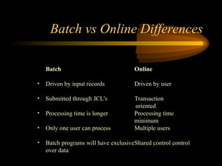
Batch Online
• Drivenby input records Driven by user
• Submitted through JCL's Transaction
oriented
• Processing time is longer Processing time
minimum
• Only one user can process Multiple users
• Batch programs will have exclusiveShared control control
over data
Batch vs Online Differences
5.
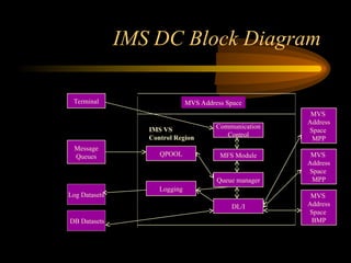
IMS DC BlockDiagram
Terminal
Message
Queues
Log Datasets
MVS
Address
Space
MPP
MVS
Address
Space
MPP
MVS
Address
Space
BMP
Communication
Control
MFS Module
Queue manager
DL/I
MVS Address Space
Logging
QPOOL
DB Datasets
IMS VS
Control Region
6.
The Resources thatIMS-DC
controls
•There are two main categories of system resources that are defined to IM S
system definition:
A.Application Resources.
B.Data communication Resources.
Application Resources:
A.Application Programs.
B. Transaction Codes.
C. Message Queues.
D.Data Bases.
7.
The Resources thatIMS-DC
controls
There are two types of application programs in the IMS DB/DC
environment.
1.MPP(Message processing programs)
2.BMP(Batch processing programs)
Out of these two application programs ,our focus is mainly on MPP
which plays major role in IMS/DC environment.The scheduling of
MP programs is entirely under the control of IMS.A message
processing program is automatically loaded by IMS when a message
to be processed by that program is received.
8.
The Resources thatIMS-DC
controls
Scheduling Techniques:
A concept of PRIORITY SCHEME is used in determining
scheduling of IMS/DC programs in MPP region.
Each transaction has two priorities associated with it:
NORMAL PRIORITY and LIMIT PRIORITY.In addition,each
transaction has a LIMIT COUNT.These three numbers are
specified in the TRANSACT macro for each transaction type.
IMS select the transaction having the highest priority.To
determine whether to use the normal priority or the limit
priority,IMS looks at how many transactions with each
transaction code are stored in each message queue.If the number
of transactions in a particular
9.
The Resources thatIMS-DC
controls
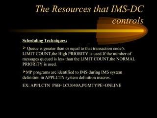
Scheduling Techniques:
Queue is greater than or equal to that transaction code’s
LIMIT COUNT,the High PRIORITY is used.If the number of
messages queued is less than the LIMIT COUNT,the NORMAL
PRIORITY is used.
MP programs are identified to IMS during IMS system
definition in APPLCTN system definition macros.
EX: APPLCTN PSB=LCU040A,PGMTYPE=ONLINE
10.
Messages,Queues
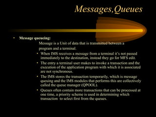
• Message queueing:
Messageis a Unit of data that is transmitted between a
program and a terminal.
• When IMS receives a message from a terminal it’s not passed
immediately to the destination, instead they go for MFS edit.
• The entry a terminal user makes to invoke a transaction and the
execution of the application program with which it is associated
are not synchronous.
• The IMS stores the transaction temporarily, which is message
queuing and the IMS modules that performs this are collectively
called the queue manager (QPOOL).
• Queues often contain more transactions that can be processed at
one time, a priority scheme is used in determining which
transaction to select first from the queues.
11.
Messages,Queues
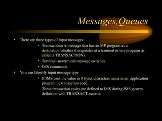
• There arethree types of input messages:
• Transactions(A message that has an MP program as a
destination,whether it originates at a terminal or in a program ,is
called a TRANSACTION).
• Terminal-to-terminal message switches
• IMS commands
• You can Identify input message type
• If IMS uses the value in 8 bytes characters name in an application
program i.e transaction code.
These transaction codes are defined to IMS during IMS system
definition with TRANSACT macros.
12.
Messages,Queues
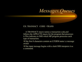
EX: TRANSACT CODE=TRANS
A TRANSACT macro names a transaction code,and
follows the APPLCTN macro for the program that processes
it.This indicates to IMS which MP program processes each
type of transaction.
•If the first 8 characters contain an LTERM name i.e message
switch
•If the input message begins with a slash IMS interprets it as
a command.
13.
IMS Data Bases
Programsthat run in the IMS/DC environment cannot indiscriminately
access any IMS data base.System definition macros do not indicate
which data bases are processed by which programs.
14.
Data Communication Resources
•A second category of resource that must be defined during IMS
system definition includes all the data communications hardware in
the communications network.Data communication hardware used ny
IMS/DC is managed by TELEPROCESSING ACCESS METHODS-
TP ACCESS METHODS.
The important physical resources under the control of IMS/DC are
communications lines that handle data communications,often
telephone lines,and remote terminals.
15.
Data Communication Resources
•LTERM NAME is the the terminal from where the message
has been generated and sent into IMS
• The terminal is connected to IMS , hence IMS recognizes the
terminal name itself no need for explicit mentioning of the
Name
• MOD – Message output descriptor is a part of MFS which
represents the medium to key in the messages from the terminals
into the IMS
16.
COBOL Basics forMPP
Programs
• The elements you code in a DC program to process messages are
extensions of the same elements you use to process data bases.
• DL/I calls for DC operations.
• PCB mask for DC operations.
• How to retrieve the input message segments.
• How to send output message segments.
• Comparison of Data base call with Data communication call.
17.
About DL/I
DL/Iactually known as Data language/1
DL/I is a interface between database and IMS/DC
It is IBM’s name for the collection of software modules
DL/I intercepts all requests that programs make for accessing the
data base
IMS uses DL/I functions to communicate with DL/I modules
18.
COBOL Basics forMPP
Programs contd...
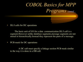
• DL/I calls for DC operations
The basic unit of I/O for a data communication DL/I call is a
segment.However unlike database segments,message segments are not
stored in hierarchically.Instead they represent the parts of a message.
• PCB mask for DC operations
A DC call must specify a linkage section PCB mask similar
to the way it is done in a DB call.
19.
COBOL Basics forMPP
Programs contd...
• This is not a database PCB mask, it’s for the message processing,
in IMS terminology it’s called the I/O PCB
• It must be the first PCB listed on the ENTRY statement
• All you have to do is specify the name of the I/O PCB on the ISRT
call that sends an output message.
COBOL Basics forMPP
Programs contd...
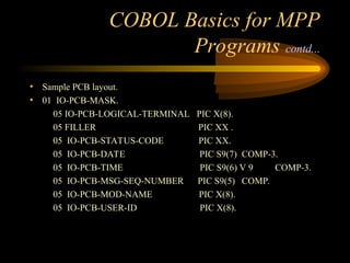
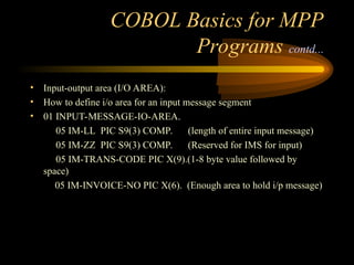
• Input-output area (I/O AREA):
• How to define i/o area for an input message segment
• 01 INPUT-MESSAGE-IO-AREA.
05 IM-LL PIC S9(3) COMP. (length of entire input message)
05 IM-ZZ PIC S9(3) COMP. (Reserved for IMS for input)
05 IM-TRANS-CODE PIC X(9).(1-8 byte value followed by
space)
05 IM-INVOICE-NO PIC X(6). (Enough area to hold i/p message)
22.
COBOL Basics forMPP
Programs contd...
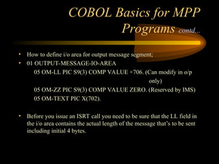
• How to define i/o area for output message segment;
• 01 OUTPUT-MESSAGE-IO-AREA
05 OM-LL PIC S9(3) COMP VALUE +706. (Can modify in o/p
only)
05 OM-ZZ PIC S9(3) COMP VALUE ZERO. (Reserved by IMS)
05 OM-TEXT PIC X(702).
• Before you issue an ISRT call you need to be sure that the LL field in
the i/o area contains the actual length of the message that’s to be sent
including initial 4 bytes.
23.
COBOL Basics forMPP
Programs contd...
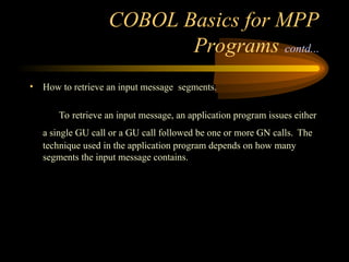
• How to retrieve an input message segments.
To retrieve an input message, an application program issues either
a single GU call or a GU call followed be one or more GN calls. The
technique used in the application program depends on how many
segments the input message contains.
24.
COBOL Basics forMPP
Programs contd...
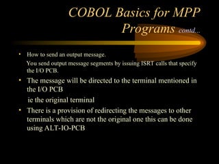
• How to send an output message.
You send output message segments by issuing ISRT calls that specify
the I/O PCB.
• The message will be directed to the terminal mentioned in
the I/O PCB
ie the original terminal
• There is a provision of redirecting the messages to other
terminals which are not the original one this can be done
using ALT-IO-PCB
25.
COBOL Basics forMPP
Programs contd...
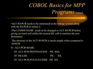
•ALT-IO-PCB needs to be mentioned in the linkage section along
with the IO-PCB to utilize it
•The LTERM NAME needs to be changed in ALT-IO-PCB before
giving an insert call unlike the normal DC call to mention the new
destination
The structure of the ALT-IO-PCB is much simple when compared to
IO/PCB
01 ALT-PCB-MASK
05 ALT-PCB-DESTINATION PIC X(8).
05 FILLER PIC XX.
05 ALT-PCB-STATUS-CODE PIC XX.
26.
COBOL Basics forMPP
Programs contd...
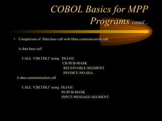
• Comparison of Data base call with Data communication call.
A data base call
CALL ‘CBLTDLI’ using DLI-GU
CR-PCB-MASK
RECEIVABLE-SEGMENT
INVOICE-NO-SSA .
A data communication call
CALL ‘CBLTDLI’ using DLI-GU
IO-PCB-MASK
INPUT-MESSAGE-SEGMENT.
27.
COBOL Basics forMPP
Programs contd...
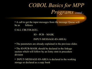
• A call to get the input messages from the message Queue will
be as follows
CALL CBLTDLI(GU,
IO – PCB – MASK
INPUT-MESSAGE-IO-AREA)
• The parameters are already explained in the previous slides
• The IO-PCB-MASK should be declared in the linkage
section which will follow by an Entry stmt in procedure
division
• INPUT-MESSAGE-IO-AREA is declared in the working
storage or declared as a copy book
28.
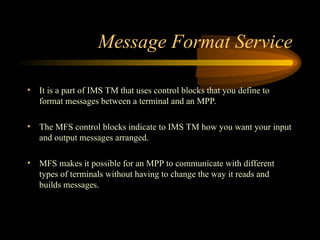
Message Format Service
•It is a part of IMS TM that uses control blocks that you define to
format messages between a terminal and an MPP.
• The MFS control blocks indicate to IMS TM how you want your input
and output messages arranged.
• MFS makes it possible for an MPP to communicate with different
types of terminals without having to change the way it reads and
builds messages.
29.
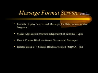
• Formats DisplayScreens and Messages for Data Communication
Programs
• Makes Application program independent of Terminal Types
• Uses 4 Control Blocks to format Screens and Messages
• Related group of 4 Control Blocks are called FORMAT SET
Message Format Service contd...
30.
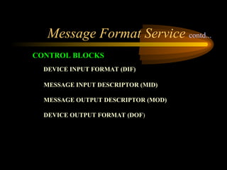
DEVICE INPUT FORMAT(DIF)
MESSAGE INPUT DESCRIPTOR (MID)
MESSAGE OUTPUT DESCRIPTOR (MOD)
DEVICE OUTPUT FORMAT (DOF)
CONTROL BLOCKS
Message Format Service contd...
Message Format Servicecontd...
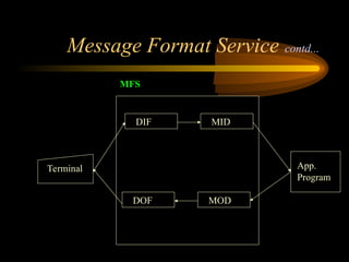
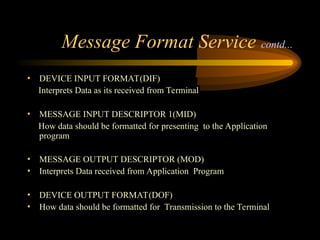
• DEVICE INPUT FORMAT(DIF)
Interprets Data as its received from Terminal
• MESSAGE INPUT DESCRIPTOR 1(MID)
How data should be formatted for presenting to the Application
program
• MESSAGE OUTPUT DESCRIPTOR (MOD)
• Interprets Data received from Application Program
• DEVICE OUTPUT FORMAT(DOF)
• How data should be formatted for Transmission to the Terminal
33.
Message Format Servicecontd...
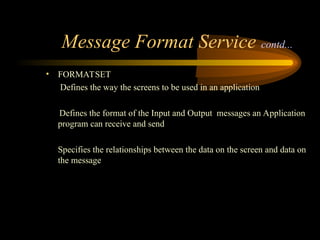
• FORMATSET
Defines the way the screens to be used in an application
Defines the format of the Input and Output messages an Application
program can receive and send
Specifies the relationships between the data on the screen and data on
the message
34.
Message Format Servicecontd...
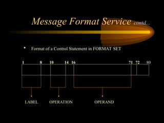
• Format of a Control Statement in FORMAT SET
1 8
LABEL OPERATION
10 14 16 71 72
OPERAND
80
35.
Message Format Servicecontd...
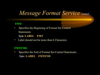
FMT:
• Specifies the Beginning of Format Set Control
Statements
Syn: LABEL FMT
• Label should not be more than 6 Characters
FMTEND:
• Specifies the End of Format Set Control Statements
Syn : LABEL FMTEND
36.
Message Format Servicecontd...
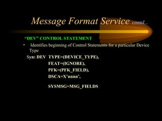
“DEV” CONTROL STATEMENT
• Identifies beginning of Control Statements for a particular Device
Type
Syn: DEV TYPE=(DEVICE_TYPE),
FEAT=(IGNORE),
PFK=(PFK_FIELD),
DSCA=X’nnnn’,
SYSMSG=MSG_FIELDS
37.
Message Format Servicecontd...
DEV - TYPE:
• Specifies the Device Models for which Device Format Blocks should
be created
VALID VALUES FOR 3270 TERMINAL:
3270,1 - 12 LINE
3270,2 - 24 LINE
(3270,A1{,A2,A3,A4,A5,A7})
38.
Message Format Servicecontd...
DEV - FEAT:
• Specifies that DIF or DOF generated for this DEV Statement will
work with the Indicated 3270 terminal Type, regardless of any Special
features installed on it
Syn: FEAT=IGNORE
39.
Message Format Servicecontd...
DEV - PFK:
• Allows to Specify how MFS should treat Program Function Keys
Syn: PFK=(MSG_FLD,1=‘01’,2=‘02’)
MSG_FLD is the field of Message and gets populated with
corresponding Value of the PF Key pressed
40.
Message Format Servicecontd...
DEV - DSCA:
• Specifies the default Terminal Action that’s performed when an
Output message is sent to a 3270 device type
Syn: DSCA=X’00A0’
DEV - SYSMSG:
• Allows to specify Device field in which messages that come to the
Terminal from IMS will be displayed
Syn: SYSMSG=ERR_FIELD
s all
ed
his
are
een
41.
Message Format Servicecontd...
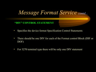
“DIV” CONTROL STATEMENT
• Specifies the device format Specification Control Statements
• There should be one DIV for each of the Format control Block (DIF or
DOF)
• For 3270 terminal type there will be only one DIV statement
42.
Message Format Servicecontd...
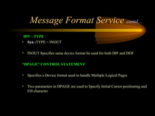
DIV - TYPE
• Syn :TYPE = INOUT
• INOUT Specifies same device format be used for both DIF and DOF
“DPAGE” CONTROL STATEMENT
• Specifies a Device format used to handle Multiple Logical Pages
• Two parameters in DPAGE are used to Specify Initial Cursor positioning and
Fill character
43.
Message Format Servicecontd...
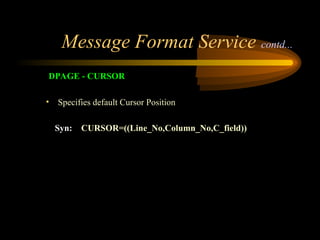
DPAGE - CURSOR
• Specifies default Cursor Position
Syn: CURSOR=((Line_No,Column_No,C_field))
44.
Message Format Servicecontd...
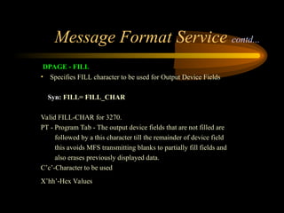
DPAGE - FILL
• Specifies FILL character to be used for Output Device Fields
Syn: FILL= FILL_CHAR
Valid FILL-CHAR for 3270.
PT - Program Tab - The output device fields that are not filled are
followed by a this character till the remainder of device field
this avoids MFS transmitting blanks to partially fill fields and
also erases previously displayed data.
C’c’-Character to be used
X’hh’-Hex Values
45.
Message Format Servicecontd...
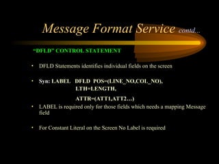
“DFLD” CONTROL STATEMENT
• DFLD Statements identifies individual fields on the screen
• Syn: LABEL DFLD POS=(LINE_NO,COL_NO),
LTH=LENGTH,
ATTR=(ATT1,ATT2…)
• LABEL is required only for those fields which needs a mapping Message
field
• For Constant Literal on the Screen No Label is required
46.
Message Format Servicecontd...
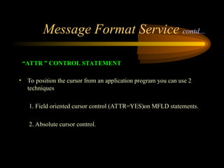
“ATTR ” CONTROL STATEMENT
• To position the cursor from an application program you can use 2
techniques
1. Field oriented cursor control (ATTR=YES)on MFLD statements.
2. Absolute cursor control.
47.
Message Format Servicecontd...
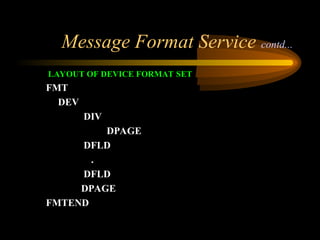
LAYOUT OF DEVICE FORMAT SET
FMT
DEV
DIV
DPAGE
DFLD
.
DFLD
DPAGE
FMTEND
48.
Message Format Servicecontd...
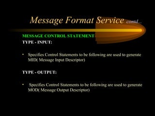
MESSAGE CONTROL STATEMENT
• Starts with MSG statement
Syn: LABEL MSG TYPE = INPUT/OUTPUT
SOR=(DF_NAME,IGNORE)
[,NXT=NEXT_SEG_NME]
[,PAGE=YES]
49.
Message Format Servicecontd...
MESSAGE CONTROL STATEMENT
TYPE - INPUT:
• Specifies Control Statements to be following are used to generate
MID( Message Input Descriptor)
TYPE - OUTPUT:
• Specifies Control Statements to be following are used to generate
MOD( Message Output Descriptor)
50.
Message Format Servicecontd...
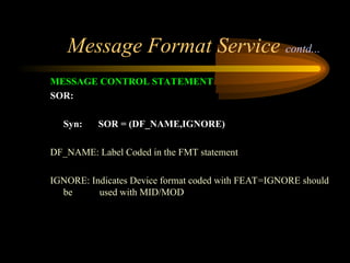
MESSAGE CONTROL STATEMENT
SOR:
Syn: SOR = (DF_NAME,IGNORE)
DF_NAME: Label Coded in the FMT statement
IGNORE: Indicates Device format coded with FEAT=IGNORE should
be used with MID/MOD
51.
Message Format Servicecontd...
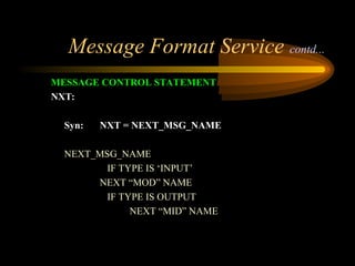
MESSAGE CONTROL STATEMENT
NXT:
Syn: NXT = NEXT_MSG_NAME
NEXT_MSG_NAME
IF TYPE IS ‘INPUT’
NEXT “MOD” NAME
IF TYPE IS OUTPUT
NEXT “MID” NAME
52.
Message Format Servicecontd...
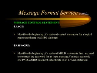
MESSAGE CONTROL STATEMENT
LPAGE:
• Identifies the beginning of a series of control statements for a logical
page subordinate to a MSG statement
PASSWORD:
• Identifies the beginning of a series of MFLD statements that are used
to construct the password for an input message.You may code only
one PASSWORD statement subordinate to an LPAGE statement
53.
Message Format Servicecontd...
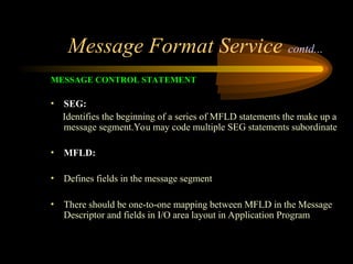
MESSAGE CONTROL STATEMENT
• SEG:
Identifies the beginning of a series of MFLD statements the make up a
message segment.You may code multiple SEG statements subordinate
• MFLD:
• Defines fields in the message segment
• There should be one-to-one mapping between MFLD in the Message
Descriptor and fields in I/O area layout in Application Program
54.
Message Format Servicecontd...
MESSAGE CONTROL STATEMENT
MFLD:
Syn: MFLD = SOURCE/DESTINATION
[,LTH= LENGTH]
[,JUST=L/R]
[,FILL = FILL_CHAR]
[,ATTR=YES]
55.
Message Format Servicecontd...
MESSAGE CONTROL STATEMENT
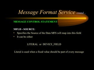
MFLD - SOURCE:
• Specifies the Source of the Data MFS will map into this field
• It can be either
LITERAL or DEVICE_FIELD
Literal is used when a fixed value should be part of every message
56.
Message Format Servicecontd...
MESSAGE CONTROL STATEMENT
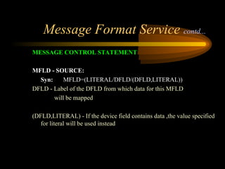
MFLD - SOURCE:
Syn: MFLD=(LITERAL/DFLD/(DFLD,LITERAL))
DFLD - Label of the DFLD from which data for this MFLD
will be mapped
(DFLD,LITERAL) - If the device field contains data ,the value specified
for literal will be used instead
57.
Message Format Servicecontd...
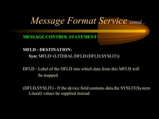
MESSAGE CONTROL STATEMENT
MFLD - DESTINATION:
Syn: MFLD=(LITERAL/DFLD/(DFLD,SYSLIT))
DFLD - Label of the DFLD into which data from this MFLD will
be mapped
(DFLD,SYSLIT) - If the device field contains data,the SYSLIT(System
Literal) values be supplied instead
58.
Message Format Servicecontd...
MESSAGE CONTROL STATEMENT
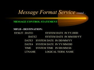
MFLD - DESTINATION:
SYSLIT : DATE1 SYSTEM DATE IN YY.DDD
DATE2 SYSTEM DATE IN MM/DD/YY
DATE3 SYSTEM DATE IN DD/MM/YY
DATE4 SYSTEM DATE IN YY/MM/DD
TIME SYSTEM TIME IN HH:MM:SS
LTNAME LOGICAL TERM. NAME
59.
Message Format Servicecontd...
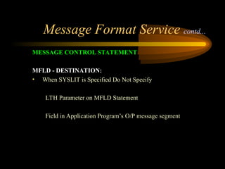
MESSAGE CONTROL STATEMENT
MFLD - DESTINATION:
• When SYSLIT is Specified Do Not Specify
LTH Parameter on MFLD Statement
Field in Application Program’s O/P message segment
60.
Message Format Servicecontd...
MESSAGE CONTROL STATEMENT
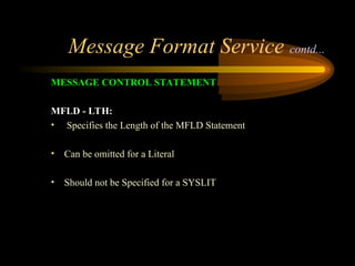
MFLD - LTH:
• Specifies the Length of the MFLD Statement
• Can be omitted for a Literal
• Should not be Specified for a SYSLIT
61.
Message Format Servicecontd...
MESSAGE CONTROL STATEMENT
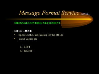
MFLD - JUST:
• Specifies the Justification for the MFLD
• Valid Values are
L - LEFT
R - RIGHT
62.
Message Format Servicecontd...
MESSAGE CONTROL STATEMENT
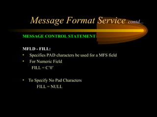
MFLD - FILL:
• Specifies PAD characters be used for a MFS field
• For Numeric Field
FILL = C’0’
• To Specify No Pad Characters
FILL = NULL
63.
Message Format Servicecontd...
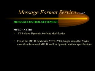
MESSAGE CONTROL STATEMENT
MFLD - ATTR:
• YES allows Dynamic Attribute Modification
• For all the MFLD fields with ATTR=YES, length should be 2 bytes
more than the normal MFLD to allow dynamic attribute specifications.
64.
Message Format Service
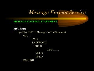
MESSAGECONTROL STATEMENT
MSGEND:
• Specifies END of Message Control Statement
MSG
LPAGE
PASSWORD
MFLD
SEG …….
MFLD
MFLD
MSGEND
65.
Important IMS libraries&
Functionalities
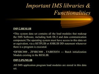
IMV2.RESLIB
•This system data set contains all the load modules that makeup
the IMS Software, including both DL/I and data communication
component.The operating system must have access to this data set
or equivalent, via a SETPLIB or JOBLIB DD statement whenever
there is a program is executed.
•DFSRC000 , ZFSRC000 , FABHX034 --- Batch initialization
Module existing in the RESLIB.
IMV2.PGMLIB
All IMS application program load modules are stored in this data
set.
66.
Important IMS libraries&
Functionalities contd..
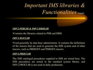
IMV2.PSBLIB & IMV2.DBDLIB
•Contains the libraries related to PSB and DBD.
IMV2.MACLIB
•Used generally by data base administrator. It contains the definitions
of the macros that are used to generate the IMS system and of other
macros, such as DBDGEN and PSBGEN macors.
IMV2.PROCLIB
The IMS cataloged procedures supplied to IMS are stored here. The
IMS procedures are stored in the standard system library, and
IMV2.PROCLIB is not used in daily production.
67.
Important IMS libraries&
Functionalities contd..
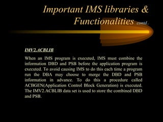
IMV2.ACBLIB
When an IMS program is executed, IMS must combine the
information DBD and PSB before the application program is
executed. To avoid causing IMS to do this each time a program
run the DBA may choose to merge the DBD and PSB
information in advance. To do this a procedure called
ACBGEN(Application Control Block Generation) is executed.
The IMV2.ACBLIB data set is used to store the combined DBD
and PSB.

![Message Format Service contd...
MESSAGE CONTROL STATEMENT
• Starts with MSG statement
Syn: LABEL MSG TYPE = INPUT/OUTPUT
SOR=(DF_NAME,IGNORE)
[,NXT=NEXT_SEG_NME]
[,PAGE=YES]](https://image.slidesharecdn.com/185387672-ims-dc-250331204000-e7c783b6/85/MAINFRAME-IBM-IMS-Information-managerment-System-48-320.jpg)
![Message Format Service contd...
MESSAGE CONTROL STATEMENT
MFLD:
Syn: MFLD = SOURCE/DESTINATION
[,LTH= LENGTH]
[,JUST=L/R]
[,FILL = FILL_CHAR]
[,ATTR=YES]](https://image.slidesharecdn.com/185387672-ims-dc-250331204000-e7c783b6/85/MAINFRAME-IBM-IMS-Information-managerment-System-54-320.jpg)