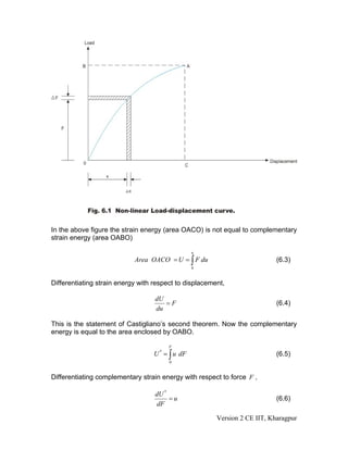
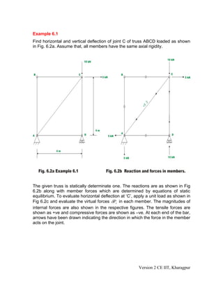
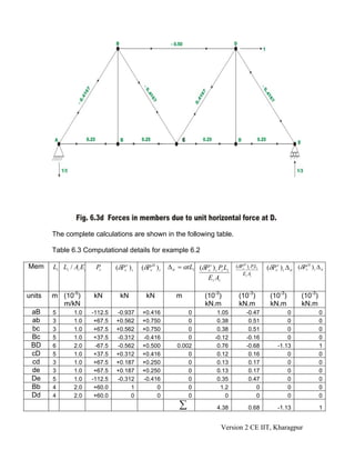
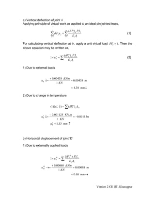
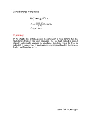
Module
              1
Energy Methods in
Structural Analysis
           Version 2 CE IIT, Kharagpur
Lesson
                   6
Engesser’s Theorem and
    Truss Deflections by
 Virtual Work Principles
                Version 2 CE IIT, Kharagpur
Instructional Objectives
After reading this lesson, the reader will be able to:
1. State and prove Crotti-Engesser theorem.
2. Derive simple expressions for calculating deflections in trusses subjected to
mechanical loading using unit-load method.
3. Derive equations for calculating deflections in trusses subjected to
temperature loads.
4. Compute deflections in trusses using unit-load method due to fabrication
errors.


6.1 Introduction
In the previous lesson, we discussed the principle of virtual work and principle of
virtual displacement. Also, we derived unit – load method from the principle of
virtual work and unit displacement method from the principle of virtual
displacement. In this lesson, the unit load method is employed to calculate
displacements of trusses due to external loading. Initially the Engesser’s
theorem, which is more general than the Castigliano’s theorem, is discussed. In
the end, few examples are solved to demonstrate the power of virtual work.


6.2 Crotti-Engesser Theorem
The Crotti-Engesser theorem states that the first partial derivative of the
                                 ( )
complementary strain energy U * expressed in terms of applied forces F j is
equal to the corresponding displacement.

                             ∂U *   n
                                  = ∑ a jk Fk = u j                          (6.1)
                             ∂Fj k =1

For the case of indeterminate structures this may be stated as,

                                     ∂U *
                                          =0                                 (6.2)
                                     ∂F j

Note that Engesser’s theorem is valid for both linear and non-linear structures.
When the complementary strain energy is equal to the strain energy (i.e. in case
of linear structures) the equation (6.1) is nothing but the statement of
Castigliano’s first theorem in terms of complementary strain energy.


                                                         Version 2 CE IIT, Kharagpur
In the above figure the strain energy (area OACO) is not equal to complementary
strain energy (area OABO)

                                                 u
                            Area OACO = U = ∫ F du                          (6.3)
                                                 0


Differentiating strain energy with respect to displacement,

                                   dU
                                      =F                                    (6.4)
                                   du

This is the statement of Castigliano’s second theorem. Now the complementary
energy is equal to the area enclosed by OABO.

                                        F
                                  U * = ∫ u dF                              (6.5)
                                        0


Differentiating complementary strain energy with respect to force F ,

                                   dU *
                                        =u                                  (6.6)
                                   dF

                                                        Version 2 CE IIT, Kharagpur
This gives deflection in the direction of load. When the load displacement
relationship is linear, the above equation coincides with the Castigliano’s first
theorem given in equation (3.8).


6.3 Unit Load Method as applied to Trusses
6.3.1 External Loading
In case of a plane or a space truss, the only internal forces present are axial as
the external loads are applied at joints. Hence, equation (5.7) may be written as,

                                n                 L
                                                      δPv Pds
                               ∑ δF j u j = ∫
                               j =1                          EA
                                                                                      (6.7)
                                                  0


wherein, δ F j is the external virtual load, u j are the actual deflections of the truss,
                                                                             P           L
δ Pv is the virtual stress resultant in the frame due to the virtual load and
                                                                          0 EA
                                                                               ds    ∫
is the actual internal deformation of the frame due to real forces. In the above
equation L, E , A respectively represent length of the member, cross-sectional
area of a member and modulus of elasticity of a member. In the unit load
method,     δF j = 1   and    all   other    components     of   virtual   forces
δFi (i = 1,2,..., j − 1, j + 1,..., n) are zero. Also, if the cross sectional area A of truss
remains constant throughout, then integration may be replaced by summation
and hence equation (6.7) may be written as,

                                      m      (δPv ) ij Pi Li
                               uj = ∑                                                    (6.8)
                                      i =1       Ei Ai

where m is the number of members, (δPv ) ij is the internal virtual axial force in
                                                Pi
member i due to unit virtual load at j and (         ) Li is the total deformation of
                                               Ei Ai
member i due to real loads. If we represent total deformation by Δ i , then

                                                      m
                                          u j = ∑ (δPv ) ij Δ i                              (6.9)
                                                      i =1


where, Δ i is the true change in length of member i due to real loads.

6.3.2 Temperature Loading
Due to change in the environmental temperature, the truss members either
expand or shrink. This in turn produces joint deflections in the truss. This may be
                                                                  Version 2 CE IIT, Kharagpur
calculated by equation (6.9). In this case, the change in length of member Δ i is
calculated from the relation,

                                     Δ i = αTLi                                  (6.10)

where α is the co-efficient of thermal expansion member, Li is the length of
member and T is the temperature change.

6.3.3 Fabrication Errors and Camber
Sometimes, there will be errors in fabricating truss members. In some cases, the
truss members are fabricated slightly longer or shorter in order to provide camber
to the truss. Usually camber is provided in bridge truss so that its bottom chord is
curved upward by an equal to its downward deflection of the chord when
subjected to dead. In such instances, also, the truss joint deflection is calculated
by equation (6.9). Here,

                                     Δi = ei                                    (6.11)

where, ei is the fabrication error in the length of the member. ei is taken as
positive when the member lengths are fabricated slightly more than the actual
length otherwise it is taken as negative.


6.4 Procedure for calculating truss deflection
1. First, calculate the real forces in the member of the truss either by method of
joints or by method of sections due to the externally applied forces. From this
                                                                             PL
determine the actual deformation ( Δ i ) in each member from the equation i i .
                                                                             Ei Ai
Assume tensile forces as positive and compressive forces as negative.

2. Now, consider the virtual load system such that only a unit load is considered
at the joint either in the horizontal or in the vertical direction, where the deflection
is sought. Calculate virtual forces (δPv )ij in each member due to the applied unit
load at the j-th joint.

3. Now, using equation (6.9), evaluate the j-th joint deflection u j .

4. If deflection of a joint needs to be calculated due to temperature change, then
determine the actual deformation ( Δ i ) in each member from the equation
Δ i = αTLi .

The application of equation (6.8) is shown with the help of few problems.
                                                           Version 2 CE IIT, Kharagpur
Example 6.1
Find horizontal and vertical deflection of joint C of truss ABCD loaded as shown
in Fig. 6.2a. Assume that, all members have the same axial rigidity.


The given truss is statically determinate one. The reactions are as shown in Fig
6.2b along with member forces which are determined by equations of static
equilibrium. To evaluate horizontal deflection at ‘C’, apply a unit load as shown in
Fig 6.2c and evaluate the virtual forces δPv in each member. The magnitudes of
internal forces are also shown in the respective figures. The tensile forces are
shown as +ve and compressive forces are shown as –ve. At each end of the bar,
arrows have been drawn indicating the direction in which the force in the member
acts on the joint.


                                                        Version 2 CE IIT, Kharagpur
Horizontal deflection at joint C is calculated with the help of unit load method.
This may be stated as,

                                           (δPv ) ic Pi Li
                            1 × u cH = ∑                                         (1)
                                              Ei Ai

For calculating horizontal deflection at C, uc , apply a unit load at the joint C as
shown in Fig.6.2c. The whole calculations are shown in table 6.1. The
calculations are self explanatory.


                                                             Version 2 CE IIT, Kharagpur
Table 6.1 Computational details for horizontal deflection at C

  Member        Length           Li / Ai Ei      Pi        (δPv ) i         (δPv ) i Pi Li
                                                                               Ei Ai
units              m              m/kN           kN          kN               kN.m
     AB             4              4/AE           0            0                 0
     BC             4              4/AE           0            0                 0
     CD             4              4/AE          -15          -1               60/AE
     DA             4              4/AE           0            0                 0
     AC           4 2            4 2 /AE         5 2           2             40 2 /AE
                                                            ∑               60 + 40 2
                                                                                AE

                            60 + 40 2 116.569
             (1)(u C ) →=
                   H
                                     =                    (Towards right)                    (2)
                                AE      AE

Vertical deflection at joint C

                                 (δPvv ) ic Pi Li
                        1× uc = ∑
                            v
                                                                                 (3)
                                     E i Ai
In this case, a unit vertical load is applied at joint C of the truss as shown in Fig.
6.2d.
Table 6.2 Computational details for vertical deflection at C

  Member        Length           Li / Ai Ei      Pi        (δPvv ) i        (δPv ) i Pi Li
                                                                               Ei Ai
units              m             m/kN             kN         kN               kN.m
     AB            4             4/AE              0          0                  0
     BC            4             4/AE              0          0                  0
     CD            4             4/AE            -15         -1               60/AE
     DA            4             4/AE              0          0                  0
     AC           4 2           4 2 /AE          5 2          0                  0
                                                            ∑                   60
                                                                                AE

                                       60   60
                        (1)(u C ) ↓=
                              v
                                          =            (Downwards)                           (4)
                                       AE AE


                                                                Version 2 CE IIT, Kharagpur
Example 6.2
Compute the vertical deflection of joint b and horizontal displacement of joint D
of the truss shown in Fig. 6.3a due to
a) Applied loading as shown in figure.
b) Increase in temperature of 250 C in the top chord BD. Assume
       1
α=           per °C , E = 2.00 × 10 5 N / mm 2 . The cross sectional areas of the
     75000
members in square centimeters are shown in parentheses.


                                                      Version 2 CE IIT, Kharagpur
Version 2 CE IIT, Kharagpur
The complete calculations are shown in the following table.

        Table 6.3 Computational details for example 6.2

Mem     Li Li / Ai Ei    Pi      (δPvv ) i   (δPvH ) i   Δ ti = αtLi (δPvv ) i Pi Li   (δPvH )i Pi Li   (δPvv ) i Δ ti (δPvH ) i Δ ti
                                                                                          Ei Ai
                                                                        Ei Ai

units   m (10-5)        kN         kN          kN           m            (10-3)         (10-3)           (10-3)          (10-3)
          m/kN                                                           kN.m           kN.m             kN.m            kN.m
 aB     5       1.0     -112.5   -0.937      +0.416              0             1.05          -0.47               0                0
 ab     3       1.0      +67.5   +0.562      +0.750              0             0.38           0.51               0                0
 bc     3       1.0      +67.5   +0.562      +0.750              0             0.38           0.51               0                0
 Bc     5       1.0      +37.5   -0.312      -0.416              0            -0.12          -0.16               0                0
 BD     6       2.0      -67.5   -0.562      +0.500          0.002             0.76          -0.68           -1.13                1
 cD     5       1.0      +37.5   +0.312      +0.416              0             0.12           0.16               0                0
 cd     3       1.0      +67.5   +0.187      +0.250              0             0.13           0.17               0                0
 de     3       1.0      +67.5   +0.187      +0.250              0             0.13           0.17               0                0
 De     5       1.0     -112.5   -0.312      -0.416              0             0.35           0.47               0                0
 Bb     4       2.0      +60.0        1           0              0              1.2              0               0                0
 Dd     4       2.0      +60.0        0           0              0                0              0               0                0
                                                              ∑               4.38             0.68          -1.13                 1


                                                                                Version 2 CE IIT, Kharagpur
a) Vertical deflection of joint b
Applying principle of virtual work as applied to an ideal pin jointed truss,

                        1                m     (δ Pv )ij PLi
                       ∑ δ Fj u j = ∑
                        j =1            i =1       Ei Ai
                                                          i
                                                                                      (1)


For calculating vertical deflection at b , apply a unit virtual load δ Fb = 1 . Then the
above equation may be written as,

                                        (δPvv ) i Pi Li
                       1× ub = ∑
                           v
                                                                                      (2)
                                           E i Ai

1) Due to external loads


                       + 0.00438 KNm
              u b ↓=                 = 0.00438 m
                            1 KN
                                                 = 4.38 mm ↓

2) Due to change in temperature


                       (1)(u b ↓) = ∑ (δPvv ) i Δ ti
                             t


                       − 0.001125 KN .m
              u b ↓=
                t
                                        = −0.00113m
                             1 KN
                       u b = 1.13 mm ↑
                         t


b) Horizontal displacement of joint ‘D’

1) Due to externally applied loads


                                      (δPvH ) i Pi Li
                       1× u    H
                               b   =∑
                                         E i Ai
                        + 0.00068 KNm
              u D →=
                H
                                      = 0.00068 m
                             1 KN
                                     = 0.68 mm →


                                                               Version 2 CE IIT, Kharagpur
2) Due to change in temperature


                    (1)(u D →) = ∑ (δPvH ) i Δ ti
                          Ht


                             0.001 KN .m
                    u D →=
                      Ht
                                         = 0.001m
                                1 KN
                    u D = 1.00 mm →
                      Ht


Summary
In this chapter the Crotti-Engessor’s theorem which is more general than the
Castigliano’s theorem has been introduced. The unit load method is applied
statically determinate structure for calculating deflections when the truss is
subjected to various types of loadings such as: mechanical loading, temperature
loading and fabrication errors.


                                                     Version 2 CE IIT, Kharagpur

M1l6

  • 1.
    Module 1 Energy Methods in Structural Analysis Version 2 CE IIT, Kharagpur
  • 2.
    Lesson 6 Engesser’s Theorem and Truss Deflections by Virtual Work Principles Version 2 CE IIT, Kharagpur
  • 3.
    Instructional Objectives After readingthis lesson, the reader will be able to: 1. State and prove Crotti-Engesser theorem. 2. Derive simple expressions for calculating deflections in trusses subjected to mechanical loading using unit-load method. 3. Derive equations for calculating deflections in trusses subjected to temperature loads. 4. Compute deflections in trusses using unit-load method due to fabrication errors. 6.1 Introduction In the previous lesson, we discussed the principle of virtual work and principle of virtual displacement. Also, we derived unit – load method from the principle of virtual work and unit displacement method from the principle of virtual displacement. In this lesson, the unit load method is employed to calculate displacements of trusses due to external loading. Initially the Engesser’s theorem, which is more general than the Castigliano’s theorem, is discussed. In the end, few examples are solved to demonstrate the power of virtual work. 6.2 Crotti-Engesser Theorem The Crotti-Engesser theorem states that the first partial derivative of the ( ) complementary strain energy U * expressed in terms of applied forces F j is equal to the corresponding displacement. ∂U * n = ∑ a jk Fk = u j (6.1) ∂Fj k =1 For the case of indeterminate structures this may be stated as, ∂U * =0 (6.2) ∂F j Note that Engesser’s theorem is valid for both linear and non-linear structures. When the complementary strain energy is equal to the strain energy (i.e. in case of linear structures) the equation (6.1) is nothing but the statement of Castigliano’s first theorem in terms of complementary strain energy. Version 2 CE IIT, Kharagpur
  • 4.
    In the abovefigure the strain energy (area OACO) is not equal to complementary strain energy (area OABO) u Area OACO = U = ∫ F du (6.3) 0 Differentiating strain energy with respect to displacement, dU =F (6.4) du This is the statement of Castigliano’s second theorem. Now the complementary energy is equal to the area enclosed by OABO. F U * = ∫ u dF (6.5) 0 Differentiating complementary strain energy with respect to force F , dU * =u (6.6) dF Version 2 CE IIT, Kharagpur
  • 5.
    This gives deflectionin the direction of load. When the load displacement relationship is linear, the above equation coincides with the Castigliano’s first theorem given in equation (3.8). 6.3 Unit Load Method as applied to Trusses 6.3.1 External Loading In case of a plane or a space truss, the only internal forces present are axial as the external loads are applied at joints. Hence, equation (5.7) may be written as, n L δPv Pds ∑ δF j u j = ∫ j =1 EA (6.7) 0 wherein, δ F j is the external virtual load, u j are the actual deflections of the truss, P L δ Pv is the virtual stress resultant in the frame due to the virtual load and 0 EA ds ∫ is the actual internal deformation of the frame due to real forces. In the above equation L, E , A respectively represent length of the member, cross-sectional area of a member and modulus of elasticity of a member. In the unit load method, δF j = 1 and all other components of virtual forces δFi (i = 1,2,..., j − 1, j + 1,..., n) are zero. Also, if the cross sectional area A of truss remains constant throughout, then integration may be replaced by summation and hence equation (6.7) may be written as, m (δPv ) ij Pi Li uj = ∑ (6.8) i =1 Ei Ai where m is the number of members, (δPv ) ij is the internal virtual axial force in Pi member i due to unit virtual load at j and ( ) Li is the total deformation of Ei Ai member i due to real loads. If we represent total deformation by Δ i , then m u j = ∑ (δPv ) ij Δ i (6.9) i =1 where, Δ i is the true change in length of member i due to real loads. 6.3.2 Temperature Loading Due to change in the environmental temperature, the truss members either expand or shrink. This in turn produces joint deflections in the truss. This may be Version 2 CE IIT, Kharagpur
  • 6.
    calculated by equation(6.9). In this case, the change in length of member Δ i is calculated from the relation, Δ i = αTLi (6.10) where α is the co-efficient of thermal expansion member, Li is the length of member and T is the temperature change. 6.3.3 Fabrication Errors and Camber Sometimes, there will be errors in fabricating truss members. In some cases, the truss members are fabricated slightly longer or shorter in order to provide camber to the truss. Usually camber is provided in bridge truss so that its bottom chord is curved upward by an equal to its downward deflection of the chord when subjected to dead. In such instances, also, the truss joint deflection is calculated by equation (6.9). Here, Δi = ei (6.11) where, ei is the fabrication error in the length of the member. ei is taken as positive when the member lengths are fabricated slightly more than the actual length otherwise it is taken as negative. 6.4 Procedure for calculating truss deflection 1. First, calculate the real forces in the member of the truss either by method of joints or by method of sections due to the externally applied forces. From this PL determine the actual deformation ( Δ i ) in each member from the equation i i . Ei Ai Assume tensile forces as positive and compressive forces as negative. 2. Now, consider the virtual load system such that only a unit load is considered at the joint either in the horizontal or in the vertical direction, where the deflection is sought. Calculate virtual forces (δPv )ij in each member due to the applied unit load at the j-th joint. 3. Now, using equation (6.9), evaluate the j-th joint deflection u j . 4. If deflection of a joint needs to be calculated due to temperature change, then determine the actual deformation ( Δ i ) in each member from the equation Δ i = αTLi . The application of equation (6.8) is shown with the help of few problems. Version 2 CE IIT, Kharagpur
  • 7.
    Example 6.1 Find horizontaland vertical deflection of joint C of truss ABCD loaded as shown in Fig. 6.2a. Assume that, all members have the same axial rigidity. The given truss is statically determinate one. The reactions are as shown in Fig 6.2b along with member forces which are determined by equations of static equilibrium. To evaluate horizontal deflection at ‘C’, apply a unit load as shown in Fig 6.2c and evaluate the virtual forces δPv in each member. The magnitudes of internal forces are also shown in the respective figures. The tensile forces are shown as +ve and compressive forces are shown as –ve. At each end of the bar, arrows have been drawn indicating the direction in which the force in the member acts on the joint. Version 2 CE IIT, Kharagpur
  • 8.
    Horizontal deflection atjoint C is calculated with the help of unit load method. This may be stated as, (δPv ) ic Pi Li 1 × u cH = ∑ (1) Ei Ai For calculating horizontal deflection at C, uc , apply a unit load at the joint C as shown in Fig.6.2c. The whole calculations are shown in table 6.1. The calculations are self explanatory. Version 2 CE IIT, Kharagpur
  • 9.
    Table 6.1 Computationaldetails for horizontal deflection at C Member Length Li / Ai Ei Pi (δPv ) i (δPv ) i Pi Li Ei Ai units m m/kN kN kN kN.m AB 4 4/AE 0 0 0 BC 4 4/AE 0 0 0 CD 4 4/AE -15 -1 60/AE DA 4 4/AE 0 0 0 AC 4 2 4 2 /AE 5 2 2 40 2 /AE ∑ 60 + 40 2 AE 60 + 40 2 116.569 (1)(u C ) →= H = (Towards right) (2) AE AE Vertical deflection at joint C (δPvv ) ic Pi Li 1× uc = ∑ v (3) E i Ai In this case, a unit vertical load is applied at joint C of the truss as shown in Fig. 6.2d. Table 6.2 Computational details for vertical deflection at C Member Length Li / Ai Ei Pi (δPvv ) i (δPv ) i Pi Li Ei Ai units m m/kN kN kN kN.m AB 4 4/AE 0 0 0 BC 4 4/AE 0 0 0 CD 4 4/AE -15 -1 60/AE DA 4 4/AE 0 0 0 AC 4 2 4 2 /AE 5 2 0 0 ∑ 60 AE 60 60 (1)(u C ) ↓= v = (Downwards) (4) AE AE Version 2 CE IIT, Kharagpur
  • 10.
    Example 6.2 Compute thevertical deflection of joint b and horizontal displacement of joint D of the truss shown in Fig. 6.3a due to a) Applied loading as shown in figure. b) Increase in temperature of 250 C in the top chord BD. Assume 1 α= per °C , E = 2.00 × 10 5 N / mm 2 . The cross sectional areas of the 75000 members in square centimeters are shown in parentheses. Version 2 CE IIT, Kharagpur
  • 11.
    Version 2 CEIIT, Kharagpur
  • 12.
    The complete calculationsare shown in the following table. Table 6.3 Computational details for example 6.2 Mem Li Li / Ai Ei Pi (δPvv ) i (δPvH ) i Δ ti = αtLi (δPvv ) i Pi Li (δPvH )i Pi Li (δPvv ) i Δ ti (δPvH ) i Δ ti Ei Ai Ei Ai units m (10-5) kN kN kN m (10-3) (10-3) (10-3) (10-3) m/kN kN.m kN.m kN.m kN.m aB 5 1.0 -112.5 -0.937 +0.416 0 1.05 -0.47 0 0 ab 3 1.0 +67.5 +0.562 +0.750 0 0.38 0.51 0 0 bc 3 1.0 +67.5 +0.562 +0.750 0 0.38 0.51 0 0 Bc 5 1.0 +37.5 -0.312 -0.416 0 -0.12 -0.16 0 0 BD 6 2.0 -67.5 -0.562 +0.500 0.002 0.76 -0.68 -1.13 1 cD 5 1.0 +37.5 +0.312 +0.416 0 0.12 0.16 0 0 cd 3 1.0 +67.5 +0.187 +0.250 0 0.13 0.17 0 0 de 3 1.0 +67.5 +0.187 +0.250 0 0.13 0.17 0 0 De 5 1.0 -112.5 -0.312 -0.416 0 0.35 0.47 0 0 Bb 4 2.0 +60.0 1 0 0 1.2 0 0 0 Dd 4 2.0 +60.0 0 0 0 0 0 0 0 ∑ 4.38 0.68 -1.13 1 Version 2 CE IIT, Kharagpur
  • 13.
    a) Vertical deflectionof joint b Applying principle of virtual work as applied to an ideal pin jointed truss, 1 m (δ Pv )ij PLi ∑ δ Fj u j = ∑ j =1 i =1 Ei Ai i (1) For calculating vertical deflection at b , apply a unit virtual load δ Fb = 1 . Then the above equation may be written as, (δPvv ) i Pi Li 1× ub = ∑ v (2) E i Ai 1) Due to external loads + 0.00438 KNm u b ↓= = 0.00438 m 1 KN = 4.38 mm ↓ 2) Due to change in temperature (1)(u b ↓) = ∑ (δPvv ) i Δ ti t − 0.001125 KN .m u b ↓= t = −0.00113m 1 KN u b = 1.13 mm ↑ t b) Horizontal displacement of joint ‘D’ 1) Due to externally applied loads (δPvH ) i Pi Li 1× u H b =∑ E i Ai + 0.00068 KNm u D →= H = 0.00068 m 1 KN = 0.68 mm → Version 2 CE IIT, Kharagpur
  • 14.
    2) Due tochange in temperature (1)(u D →) = ∑ (δPvH ) i Δ ti Ht 0.001 KN .m u D →= Ht = 0.001m 1 KN u D = 1.00 mm → Ht Summary In this chapter the Crotti-Engessor’s theorem which is more general than the Castigliano’s theorem has been introduced. The unit load method is applied statically determinate structure for calculating deflections when the truss is subjected to various types of loadings such as: mechanical loading, temperature loading and fabrication errors. Version 2 CE IIT, Kharagpur