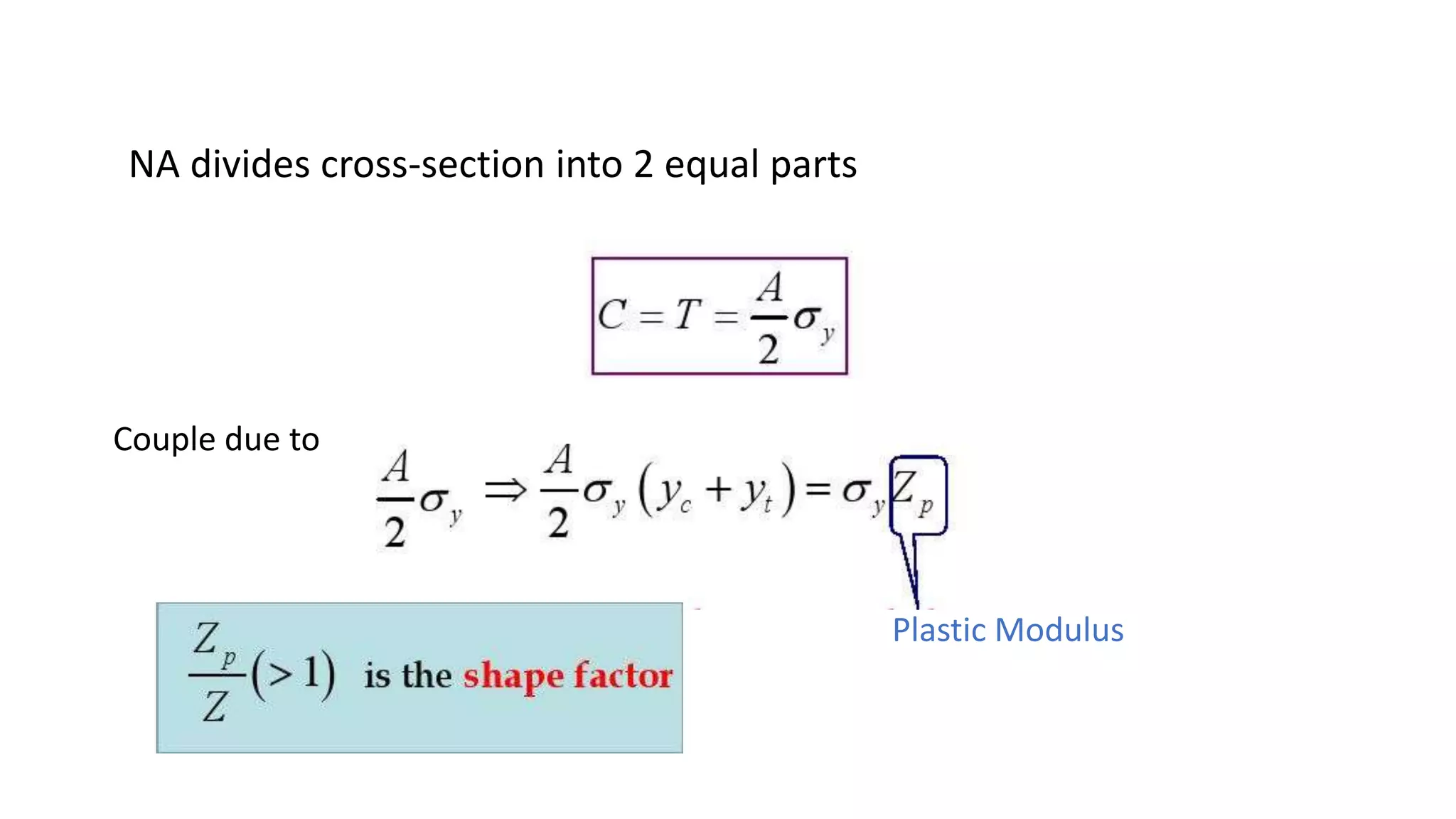
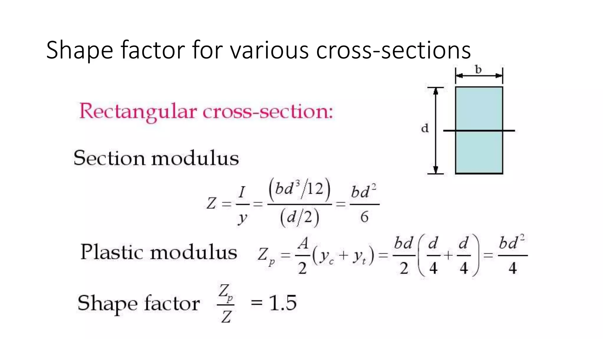
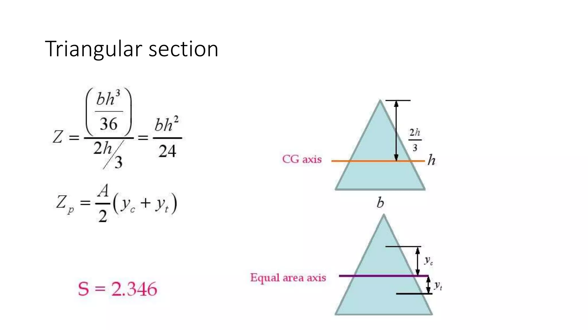
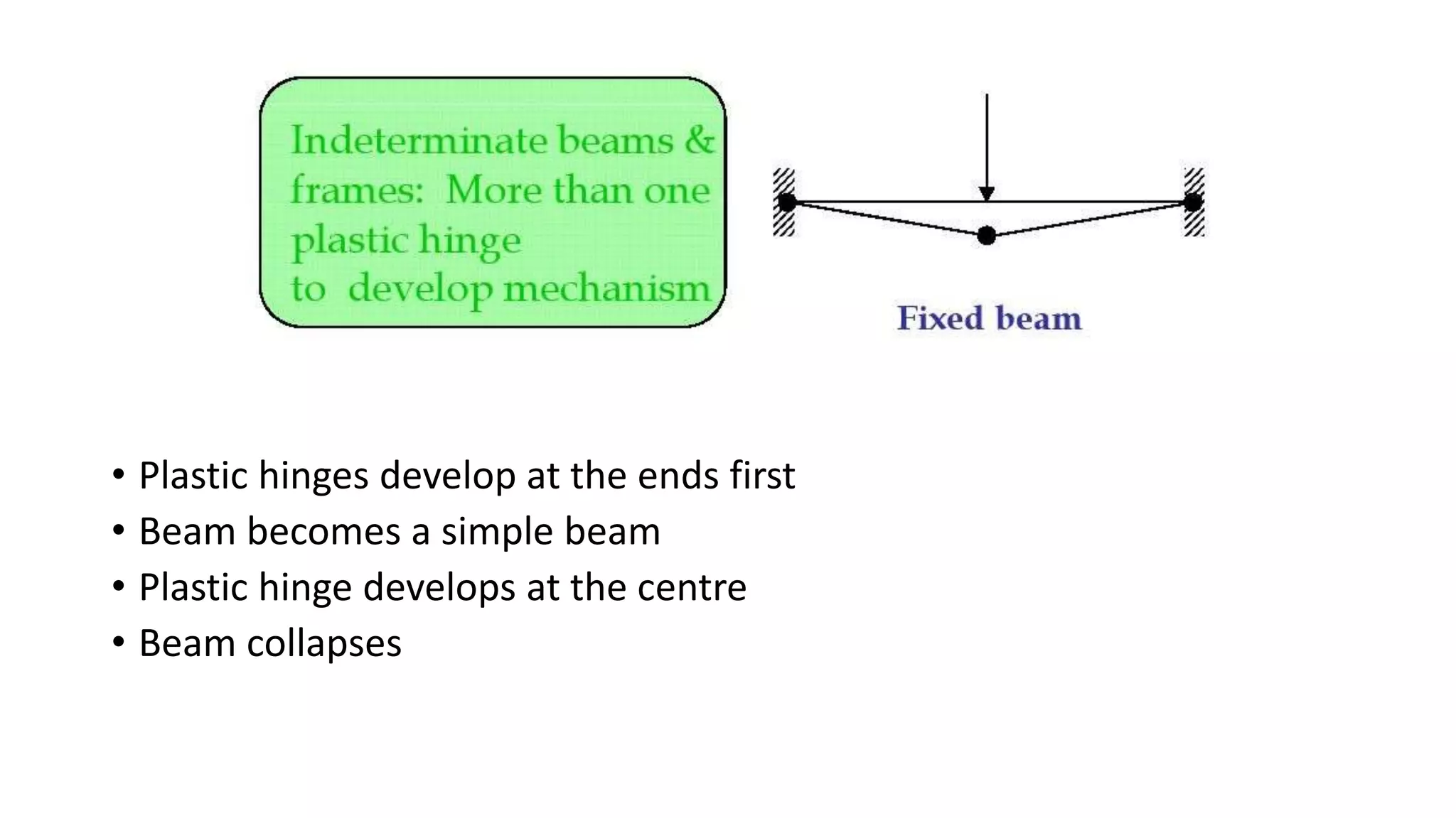
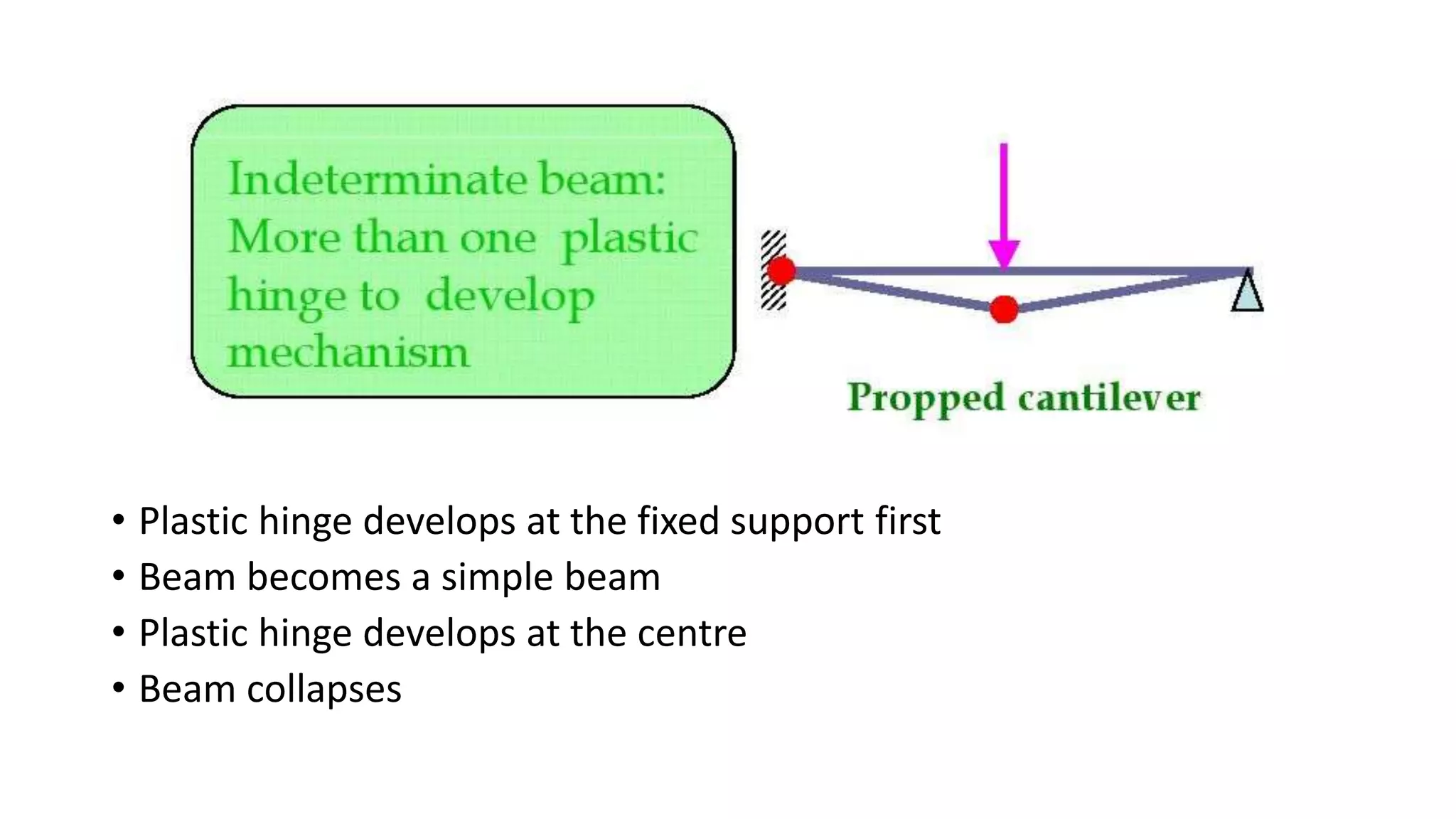
Seminar on
“Plastic Analysis”
By:
Shubham Satish Babar
Department of Civil Engineering
2015-16
1) Introduction
2) Plastic hinge concept
3) Plastic section modulus & Shape factor
4) Collapse mechanism
5) Determination of collapse load
CONTENT-
Materials
1) Introduction -
•Elastic •Elastic-Perfectly plastic
Assumptions
•Plane sections remain plane in plastic condition
• Stress-strain relation is identical both in compression
and tension
Process of yielding of a section
•Let a cross-section increases gradually.
•Within elastic limit, M = σ .Z
•Z is section modulus, I/y
•Elastic limit –yield stresses reached
My = σ y.Z
•When moment is increased, yield spreads into inner When
moment is increased, yield spreads into inner fibres.
Remaining portion still elastic
• Finally, the entire cross-section yields
Change in stress distribution during yielding
Rectangular cross section
M<My M=My My<M<Mp M=Mp
Inverted T section
Example -
2) Plastic hinge concept
•When the section is completely yielded, the section is fully plastic
• A fully plastic section behaves like a hinge – Plastic hinge
Plastic hinge is defined as an yielded zone due to bending in a
structural member, at which large rotations can occur at a section at
constant plastic moment, MP
Moment at which the entire section is under yield stress
3) Plastic section modulus & Shape factor -
Couple due to
Plastic Modulus
NA divides cross-section into 2 equal parts
Shape factor for various cross-sections
Circular section
Triangular section
I section
Beam mechanism -
4) Collapse mechanism -
• Plastic hinges develop at the ends first
• Beam becomes a simple beam
• Plastic hinge develops at the centre
• Beam collapses
• Plastic hinge develops at the fixed support first
• Beam becomes a simple beam
• Plastic hinge develops at the centre
• Beam collapses
Panel mechanism/sway mechanism
Gable Mechanism
Methods of Plastic Analysis
• Static method or Equilibrium method
Lower bound: A load computed on the basis of an assumed
equilibrium BM diagram in which the moments are not
greater than MP is always less than (or at the worst equal to)
the true ultimate load.
• Kinematic method or Mechanism method or Virtual work
Work performed by the external loads is equated to the
internal work absorbed by plastic hinges
Upper bound: A load computed on the basis of an assumed
mechanism is always greater than (or at the best equal to) the
true ultimate load.
The Plastic Hinges occur-
• At the point of maximum moment.
• At the connection involving change in geometry.
• Under the concentrated load.
• At the point of zero shear in span, loaded by uniformly
distribute load.
5) Determination of collapse load -
1. Simple beam
• Virtual work method
2. Fixed beam with UDL
Equilibrium :
Virtual Work :
3. Fixed beam with point load
4. Fixed beam with eccentric point load
Virtual Work :
5. Propped cantilever with point load at
midspan
6. Propped cantilever with UDL
REFERENCES -
• “Plastic Analysis” by Dr. Rajesh K. N. (Assistant Professor in Civil
Engineering Assistant Professor in Civil Engineering Govt. College of
Engineering, Kannur)
• Fundamentals of Structural Steel Design by M L Gambhir

Plastic analysis

  • 1.
    Seminar on “Plastic Analysis” By: ShubhamSatish Babar Department of Civil Engineering 2015-16
  • 2.
    1) Introduction 2) Plastichinge concept 3) Plastic section modulus & Shape factor 4) Collapse mechanism 5) Determination of collapse load CONTENT-
  • 3.
    Materials 1) Introduction - •Elastic•Elastic-Perfectly plastic
  • 4.
    Assumptions •Plane sections remainplane in plastic condition • Stress-strain relation is identical both in compression and tension
  • 5.
    Process of yieldingof a section •Let a cross-section increases gradually. •Within elastic limit, M = σ .Z •Z is section modulus, I/y •Elastic limit –yield stresses reached My = σ y.Z •When moment is increased, yield spreads into inner When moment is increased, yield spreads into inner fibres. Remaining portion still elastic • Finally, the entire cross-section yields
  • 6.
    Change in stressdistribution during yielding Rectangular cross section M<My M=My My<M<Mp M=Mp
  • 7.
  • 8.
    2) Plastic hingeconcept •When the section is completely yielded, the section is fully plastic • A fully plastic section behaves like a hinge – Plastic hinge Plastic hinge is defined as an yielded zone due to bending in a structural member, at which large rotations can occur at a section at constant plastic moment, MP
  • 9.
    Moment at whichthe entire section is under yield stress 3) Plastic section modulus & Shape factor -
  • 10.
    Couple due to PlasticModulus NA divides cross-section into 2 equal parts
  • 11.
    Shape factor forvarious cross-sections
  • 12.
  • 13.
  • 14.
  • 15.
    Beam mechanism - 4)Collapse mechanism -
  • 16.
    • Plastic hingesdevelop at the ends first • Beam becomes a simple beam • Plastic hinge develops at the centre • Beam collapses
  • 17.
    • Plastic hingedevelops at the fixed support first • Beam becomes a simple beam • Plastic hinge develops at the centre • Beam collapses
  • 18.
  • 19.
  • 20.
    Methods of PlasticAnalysis • Static method or Equilibrium method Lower bound: A load computed on the basis of an assumed equilibrium BM diagram in which the moments are not greater than MP is always less than (or at the worst equal to) the true ultimate load. • Kinematic method or Mechanism method or Virtual work Work performed by the external loads is equated to the internal work absorbed by plastic hinges Upper bound: A load computed on the basis of an assumed mechanism is always greater than (or at the best equal to) the true ultimate load.
  • 21.
    The Plastic Hingesoccur- • At the point of maximum moment. • At the connection involving change in geometry. • Under the concentrated load. • At the point of zero shear in span, loaded by uniformly distribute load.
  • 22.
    5) Determination ofcollapse load - 1. Simple beam
  • 23.
  • 24.
    2. Fixed beamwith UDL
  • 25.
  • 26.
    3. Fixed beamwith point load
  • 27.
    4. Fixed beamwith eccentric point load
  • 28.
  • 29.
    5. Propped cantileverwith point load at midspan
  • 31.
  • 33.
    REFERENCES - • “PlasticAnalysis” by Dr. Rajesh K. N. (Assistant Professor in Civil Engineering Assistant Professor in Civil Engineering Govt. College of Engineering, Kannur) • Fundamentals of Structural Steel Design by M L Gambhir